

Page 1

EOS-4000
2-CH PoCL Embedded Vision System
User’s Manual
Manual Rev.: 2.00
Revision Date: Sept. 27, 2013
Part No: 50-1Z154-1000
Advance Technologies; Automate the World.
Page 2

Revision History
Revision Release Date Description of Change(s)
2.00 Sept. 27, 2013 Initial release
ii
Page 3

EOS-4000
Preface
Copyright 2013 ADLINK Technology, Inc.
This document contains proprietary information protected by copyright. All rights are reserved. No part of this manual may be reproduced by any mechanical, electronic, or other means in any form
without prior written permission of the manufacturer.
Disclaimer
The information in this document is subject to change without prior
notice in order to improve reliability, design, and function and does
not represent a commitment on the part of the manufacturer.
In no event will the manufacturer be liable for direct, indirect, special, incidental, or consequential damages arising out of the use or
inability to use the product or documentation, even if advised of
the possibility of such damages.
Environmental Responsibility
ADLINK is committed to fulfill its social responsibility to global
environmental preservation through compliance with the European Union's Restriction of Hazardous Substances (RoHS) directive and Waste Electrical and Electronic Equipment (WEEE)
directive. Environmental protection is a top priority for ADLINK.
We have enforced measures to ensure that our products, manufacturing processes, components, and raw materials have as little
impact on the environment as possible. When products are at their
end of life, our customers are encouraged to dispose of them in
accordance with the product disposal and/or recovery programs
prescribed by their nation or company.
Trademarks
Product names mentioned herein are used for identification purposes only and may be trademarks and/or registered trademarks
of their respective companies.
Preface iii
Page 4

Conventions
Take note of the following conventions used throughout this
manual to make sure that users perform certain tasks and
instructions properly.
Additional information, aids, and tips that help users perform
tasks.
NOTE:
NOTE:
Information to prevent minor physical injury, component dam-
age, data loss, and/or program corruption when trying to com-
CAUTION:
WARNING:
plete a task.
Information to prevent serious physical injury, component
damage, data loss, and/or program corruption when trying to
complete a specific task.
iv Preface
Page 5

EOS-4000
Table of Contents
Revision History...................................................................... ii
Preface.................................................................................... iii
List of Figures........................................................................ ix
List of Tables.......................................................................... xi
1 Introduction ........................................................................ 1
1.1 Overview.............................................................................. 1
1.2 Features............................................................................... 1
1.3 Specifications....................................................................... 2
1.4 Schematics .......................................................................... 4
1.5 Front Panel I/O Connectors................................................. 6
1.5.1 LED Indicators ............................................................ 7
1.5.2 Power Switch.............................................................. 7
1.5.3 Reset Button............................................................... 7
1.5.4 PS/2 Connector .......................................................... 7
1.5.5 Dual Gigabit Ethernet Ports........................................ 8
1.5.6 DVI-I connector........................................................... 9
1.5.7 USB 2.0 Connectors................................................. 10
1.5.8 USB 3.0 Connectors................................................. 10
1.5.9 CFast Slot................................................................. 11
1.5.10 Camera Link Ports.................................................... 12
1.5.11 Camera Link LED Indicators..................................... 13
1.6 Rear Panel I/O Connectors................................................ 14
1.6.1 DC Power Supply Connector.................................... 15
1.6.2 DB-62P COM Port Connector .................................. 16
1.6.3 Trigger Input/Strobe Output Connector .................... 17
1.6.4 Encoder Input Port.................................................... 18
1.7 Internal I/O connectors ...................................................... 20
Table of Contents v
Page 6

1.7.1 Clear CMOS and ME RTC Register Jumpers .......... 21
1.7.2 DC 12V Fan Connector ............................................ 21
1.7.3 DC 12V Fan Connector (reserved) ........................... 21
1.7.4 USB 2.0 Type A Connector ...................................... 21
1.7.5 SUMIT Connector ..................................................... 22
1.7.6 SATA Connectors ..................................................... 23
1.8 General Purpose Digital Signals........................................ 24
1.8.1 General Purpose Digital Output (EDO)..................... 24
1.8.2 General Purpose Digital Input (EDI) ......................... 25
2 Getting Started.................................................................. 27
2.1 Unpacking Checklist .......................................................... 27
2.2 Installing Memory............................................................... 28
2.3 Installing a Hard Disk Drive................................................ 30
2.4 Installing the USB Dongle.................................................. 34
2.5 Installing Wallmount Brackets............................................ 36
2.6 Operating System Installation............................................ 37
2.6.1 Windows 7 ................................................................ 37
2.7 Driver Installation ............................................................... 38
2.7.1 Chipset Driver Installation......................................... 39
2.7.2 Graphics Driver Installation....................................... 39
2.7.3 Ethernet Driver Installation ....................................... 39
2.7.4 USB 3.0 Driver Installation........................................ 40
2.7.5 ME (Management Engine Components)
Software Installation ................................................. 40
2.7.6 Frame Grabber And Digital Input/Output
Driver Installation ...................................................... 40
A Appendix: BIOS Setup.......................................................43
A.1 Main ................................................................................... 43
A.1.1 System Time/System Date ....................................... 44
A.2 Advanced ........................................................................... 44
vi Table of Contents
Page 7

EOS-4000
A.2.1 ACPI Settings ........................................................... 45
A.2.2 CPU Configuration.................................................... 46
A.2.3 Onboard Device Configuration ................................. 48
A.2.4 Advanced Power Management ................................ 49
A.2.5 SATA Configuration.................................................. 50
A.2.6 Intel Anti-Theft Technology Configuration ................ 51
A.2.7 AMT Configuration.................................................... 52
A.2.8 USB Configuration.................................................... 53
A.2.9 Super I/O Configuration............................................ 54
A.2.10 Hardware Monitor ..................................................... 55
A.2.11 Serial Port Console Redirection ............................... 56
A.2.12 Serial Port for Out-of-Band Management/EMS ........ 56
A.3 Chipset............................................................................... 57
A.3.1 System Agent (SA) Configuration............................. 58
A.4 Boot ................................................................................... 60
A.4.1 Boot Configuration.................................................... 60
A.4.2 Boot Option Priorities................................................ 61
A.5 Security .............................................................................. 61
A.6 Exit ..................................................................................... 62
Important Safety Instructions.............................................. 65
Getting Service...................................................................... 67
Table of Contents vii
Page 8

This page intentionally left blank.
viii Table of Contents
Page 9

EOS-4000
List of Figures
Figure 1-1: EOS-4000 Front View...................................................... 4
Figure 1-2: EOS-4000 Rear View ...................................................... 4
Figure 1-3: EOS-4000 Top View ........................................................ 5
Figure 1-4: EOS-4000 Right Side View.............................................. 5
Figure 1-5: EOS-4000 Left Side View ................................................ 6
Figure 1-6: Front Panel I/O Connectors ............................................. 6
Figure 1-7: Gigabit Ethernet Ports ..................................................... 9
Figure 1-8: DVI-I connector................................................................ 9
Figure 1-9: Camera Link Port Connections...................................... 12
Figure 1-10: Camera Link LED Indicators.......................................... 13
Figure 1-11: Rear Panel I/O Connectors............................................ 14
Figure 1-12: DC Power Connector..................................................... 15
Figure 1-13: Trigger Input/Strobe Output Connector ......................... 17
Figure 1-14: Encoder Input Port......................................................... 19
Figure 1-15: EOS-4000 Mainboard Top View .................................... 20
Figure 1-16: EOS-4000 Mainboard Underside View.......................... 23
List of Figures ix
Page 10

This page intentionally left blank.
xList of Figures
Page 11

EOS-4000
List of Tables
Table 1-1: Front Panel I/O Connector Legend.................................. 7
Table 1-2: LED Indicators ................................................................. 7
Table 1-3: Gigabit Ethernet Port Features........................................ 8
Table 1-4: Active/Link LED ............................................................... 9
Table 1-5: Speed LED ...................................................................... 9
Table 1-6: DVI-I Connector Signals ................................................ 10
Table 1-7: Camera Link Port Connections Legend......................... 12
Table 1-8: Camera Link LED Indicators Legend............................. 13
Table 1-9: Rear Panel I/O Connector Legend ................................ 14
Table 1-10: DB-62P Connector Pin Assignment............................... 16
Table 1-11: Trigger Input/Strobe Output Specifications.................... 17
Table 1-12: Trigger Input/Strobe Output Pin Definitions ................... 18
Table 1-13: Encoder Input Configurations ........................................ 18
Table 1-14: Encoder Input Port Pin Assignment............................... 19
Table 1-15: Mainboard Connector Legend ....................................... 20
Table 1-16: SUMIT Pin Definitions.................................................... 22
Table A-1: Restore On Power Loss Options ................................... 49
List of Tables xi
Page 12

This page intentionally left blank.
xii List of Tables
Page 13

1 Introduction
1.1 Overview
The EOS-4000 is a rugged compact embedded vision system
equipped with the 3rd Generation IntelCore™ i5/i7 processor, providing dual independent PoCL (power over Camera Link) ports
with data transfer up to 2.56 Gb/s, and pixel clock rates up to 85
MHz for high speed capture of large images, greatly enhancing
computing power and connectivity with minimal footprint.
The EOS-4000 supports 2-CH PoCL Camera Link as base configuration to reduce cabling burdens and eliminate the need for
external power adapters. In addition, the EOS-4000 supports
64-bit memory addressing for large address space vision applications.
The EOS-4000’s rich I/O capability includes trigger and encoder
input and two independent RS-232 serial communication ports,
reducing host computer loading. 64 isolated digital I/Os, digital filter, dual storage, internal USB port, and 1 kbit programmable
EEPROM all ideally equip the EOS-4000 to integrate, deploy, and
manage copy protection or authentication of software licenses for
system development, further accelerating time to market.
EOS-4000
Combining increased computing power with multi-channel connectivity and a ready-to-deploy application platform, the
EOS-4000 delivers embedded vision ideally suited for machine
vision applications.
1.2 Features
X 230W X 206D X 82H mm (9.06 X 8.11 X 3.23 in), compact and
rugged system design
X 3rd Generation Intel
X Up to 2-CH PoCL, base Camera Link® configuration
X Internal USB port and 1 kbit programmable EEPROM
X 64-CH isolation DI/O with digital filter
X Supports two SATA ports and one CFast slot
Introduction 1
®
Core™ i5/i7 processors
Page 14
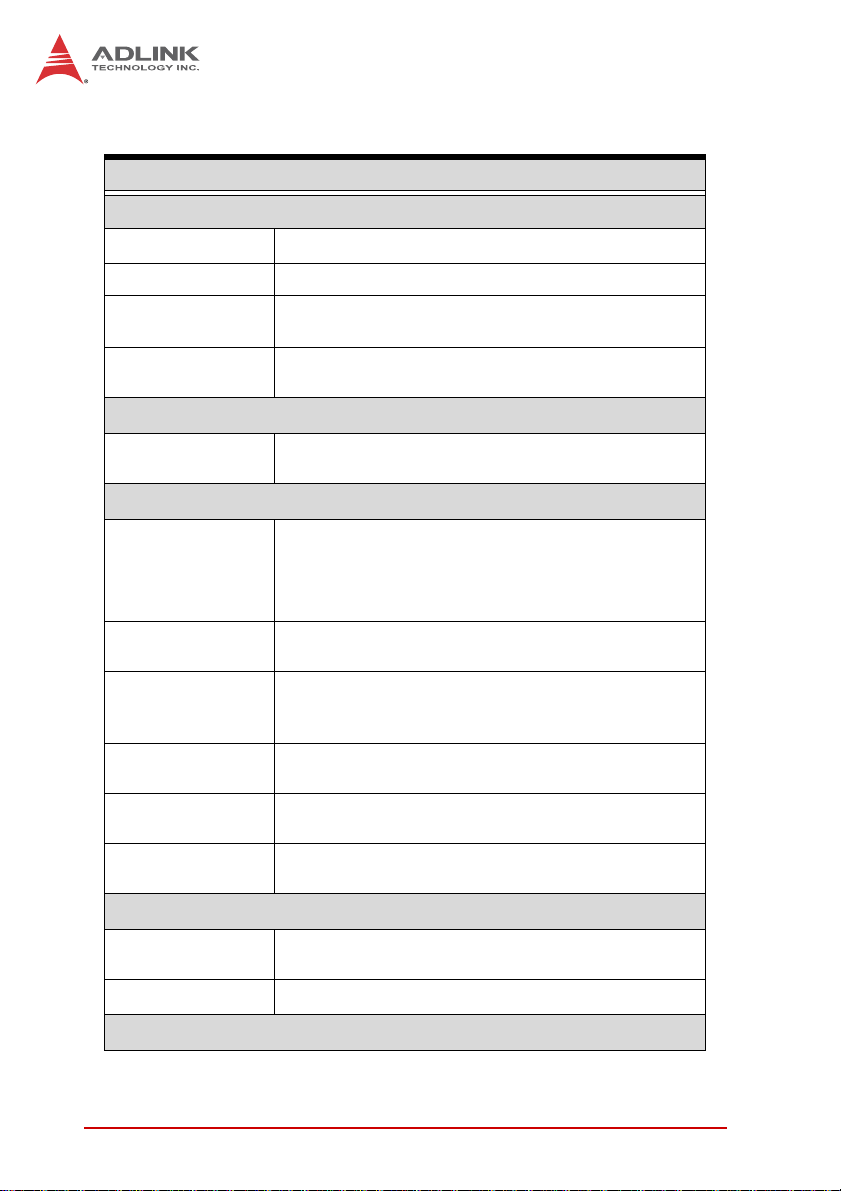
1.3 Specifications
General Specifications
System Core
Processor IntelCore™ i7-3610QM, i5-3610ME
®
Chipset Intel
Video
Memory
Camera Interface
Camera Link
I/O Interface
DI/O
Ethernet
Serial Port
USB
Trigger I/O
KB/MS
Power Supply
DC Input
AC Input Optional 150 W external AC-DC adapter
QM6 Express
VGA+DVI-D output by DVI-I connector- analog CRT,
supports QXGA, 2048 x 1536 resolution
2 socket slot for DDR3 1066/1333/1600 MHz
SODIMM module (Max. capacity 16GB)
2-CH power over Camera Link, base configuration,
up to 85 MHz
X 32 DI, 32 DO COS interrupt for all digital
input
X 2.5 kV isolation protection
X Configurable digital filter (0.25 µs-131 ms)
®
2x GbE port (1x Intel
82574L, 1x Intel®
82579LM(PHY)) with WOL function on each port
2x software-programmable RS-232/422/485 (COM1
& COM2)
2x RS-232 (COM3 & COM4)
4x USB 2.0 ports
2x USB 3.0 ports
2 trigger input
1 encoder input
1x PS/2 for keyboard and mouse (requires S3
wakeup)
Built-in 9-32 VDC wide-range DC 3P pluggable
connector with latch (GND, V-, V+)
Security
2Introduction
Page 15

EOS-4000
General Specifications
USB
ID 1kBit EEPROM
Storage
SATA HDD
CFast 1x CFast slot, SATA 3Gb/s compatible
Mechanical
Dimensions 230W X 206D X 82H mm (9.06 X 8.11 X 3.23 in)
Weight 3 kg (6.61 lb)
Mounting Wall- and rail-mount kit
OS
Operating system Windows 7/7 Embedded
Environmental
Operating
temperature
Storage
temperature
Humidity Approx. 95% @ 40° C (non-condensing)
1x internal USB port supporting installation of a USB
dongle for security function.
2x SATA port for 2.5" HDD/SSD installation
RAID 0/1/5/10
0° to 55° C (32 to 131° F)
-40° to 85° C (-40 to 185° F) (excl. HDD/SDD/CFast)
CFast
Vibration
(Operating)
Shock
EMI CE, FCC Class A
Introduction 3
SSD
HDD
Operating, 30 Grms, half sine 11ms duration
(CF or SSD)
5 Grms, 5-500 Hz, 3 axes
3 Grms, 5-500 Hz, 3 axes
0.5 Grms, 5-500 Hz, 3 axes
Page 16

1.4 Schematics
All units are in millimeters (mm)
NOTE:
NOTE:
Figure 1-1: EOS-4000 Front View
82
230
Figure 1-2: EOS-4000 Rear View
4Introduction
Page 17

EOS-4000
206.3
Figure 1-3: EOS-4000 Top View
Figure 1-4: EOS-4000 Right Side View
Introduction 5
Page 18

Figure 1-5: EOS-4000 Left Side View
1.5 Front Panel I/O Connectors
K L
J
I
H
Figure 1-6: Front Panel I/O Connectors
A LED indicators
B Power switch
C Reset switch
D PS/2 keyboard & mouse
E Dual Gigabit Ethernet ports
F DVI-I connector
A
B
DEFG
C
6Introduction
Page 19

EOS-4000
G USB 2.0 connectors x4 (Type A)
H USB3.0 connector (Type A) x2
I CFast connector (push-push,type II)
J Camera Link port LED indicators
K Camera Link port x2
L 32 channel isolation DIO connector
Table 1-1: Front Panel I/O Connector Legend
1.5.1 LED Indicators
In addition to an LED on the power switch, two LEDs on the front
panel indicate as follows..
LED indicator Color Description
X If lit continuously, indicates no
physical storage is connected
Diagnostic Yellow
HDD Green
T able 1-2: LED Indicators
X If blinking, indicates no mem-
ory is installed on either
SO-DIMM socket
When blinking, indicates the SATA hard
drive is active
1.5.2 Power Switch
The power switch is non-latched, with a blue LED indicator. System is turned on when the button is depressed, and the power
LED lights. If the system hangs, depressing the switch for 5 seconds turns the system off completely.
1.5.3 Reset Button
The reset button executes a hard reset.
1.5.4 PS/2 Connector
The EOS-4000 provides connectors for PS/2 keyboard and
mouse, either singly or with a Y-cable to connect both at the same
time.
Introduction 7
Page 20

1.5.5 Dual Gigabit Ethernet Ports
The EOS-4000 provides two Gigabit Ethernet ports on the front
panel, an Intel® 82574IT Gigabit Ethernet Controller and Intel®
82579LM Gigabit Ethernet PHY, with features as follows.
Intel® 82574IT Gigabit Ethernet
Controller
Advanced error reporting 802.3x flow control-compliant
Message signaled interrupts IEEE 802.1p and 802.1q support
TCP segmentation
offload/large-send support
802.3x flow control-compliant 10/100/1000 IEEE 802.3-compliant
IEEE 802.1p and 802.1q support
10/100/1000 IEEE 802.3-compliant Wake-On-LAN feature
Automatic MDI/MDIX crossover at all
speeds
ACPI 2.0 specification
Wake-On-LAN
Fully integrated ASF 2.0 functionality
with on-chip μc
SMBus 2.0 master interface for ASF
functionality
Preboot eXecution environment
(PXE) flash interface support
9 KB jumbo frame support IEEE 802.1p and 802.1q support
LAN Teaming Function support
Intel® 82579LM Gigabit Ethernet
PHY
Energy efficient
Ethernet(EEE)802.3az support
Automatic MDI/MDIX crossover at all
speeds
Support Intel® AMT 7.0
Reduced power consumption during
normal operation and power down
modes
Preboot eXecution Environment
(PXE) flash interface support
9 KB jumbo frame support
Supports LAN Teaming function
802.3x flow control-compliant
Energy Efficient
Ethernet(EEE)802.3az support
Table 1-3: Gigabit Ethernet Port Features
Both Gigabit Ethernet ports provide function indication through
LED display, as follows, with a yellow Activity indicator LED on the
right side of the port, and a green/orange Speed indicator LED on
the left. LED function is the same for both ports
8Introduction
Page 21

Figure 1-7: Gigabit Ethernet Ports
LED Color Status Description
OFF Ethernet port is disconnected.
Yell ow
LED Color Status Description
Green/Oran
ge
ON Ethernet port is connected with no activity.
Flashing Ethernet port is connected and active.
Table 1-4: Active/Link LED
OFF 10 Mbps
Green 100 Mbps
Orange 1000 Mbps
EOS-4000
Table 1-5: Speed LED
1.5.6 DVI-I connector
The EOS-4000 provides one DVI-I connector for connection to an
external monitor. The DVI-I connector can be separated into VGA
and DVI-D (single link) interfaces.
Figure 1-8: DVI-I connector
Introduction 9
Page 22

PIN Signal PIN Signal PIN Signal PIN Signal
1 DVIdata 2- 9 DVIdata 1- 17 DVIdata 0- C1
2 DVIdata 2+ 10 DVIdata 1+ 18 DVIdata 0+ C2
3 GND 11 GND 19 GND C3
4 CRT DDC clock 12 N/C 20 N/C C4
5 CRT DDC data 13 N/C 21 N/C C5
6 DVIDC clock 14 +5V 22 GND
7 DVIDC data 15 GND 23 DVI clock +
8
Analog vert.
sync
T able 1-6: DVI-I Connector Signals
16
Hot plug
detect
24 DVI clock -
Analog
Red
Analog
Green
Analog
Blue
Analog
horiz.
sync
Analog
GND
1.5.7 USB 2.0 Connectors
The EOS-4000 provides four Type A USB 2.0 ports on the front
panel. All are compatible with Hi-Speed, full-speed, and low-speed
USB devices.
The EOS-4000 supports multiple boot devices, including USB
flash, USB external HD, USB floppy, and USB CD-ROM drives.
Boot priority and device can be configured in BIOS. Please refer to
Section A.2.8 USB Configuration for details.
1.5.8 USB 3.0 Connectors
The EOS-4000 provides two Type A USB 3.0 ports on the front
panel. Based on the TI TUSB7320RKM USB host controller, connection to the host system is achieved through a PCIe x1 Gen2
10 Introduction
Page 23

EOS-4000
interface, supporting SuperSpeed, Hi-Speed, full-speed, and
low-speed transmission for the downstream USB 3.0 ports.
The EOS-4000 supports multiple boot devices, including USB
flash, USB external HD, and USB CD-ROM drives. Boot priority
and device can be configured in BIOS.
While the USB 3.0 ports allow boot from CD-ROM, OS
installation via CD-ROM is not supported.
NOTE:
NOTE:
1.5.9 CFast Slot
The EOS-4000 is equipped with a type II push-push CFast host
connector on the front panel, connecting to the host controller by
SATA interface. Data transfer rates up to 3.0Gb/s(300MB/s)/
1.5Gb/s(150MB/s) are supported. The host SATA controller provides a legacy operating mode using I/O space, and an AHCI
operating mode using memory space. The CFast card can function as a storage device for system installation.
Introduction 11
Page 24

1.5.10 Camera Link Ports
13
26
14
Figure 1-9: Camera Link Port Connections
Pin Signal Pin Signal
1 Inner shield or Power 14 Inner shield or Power return
2 CC4- 15 CC4+
3 CC3+ 16 CC3-
4 CC2- 17 CC2+
5 CC1+ 18 CC1-
6 SerTFG+ 19 SerTFG-
7SerTC- 20SerTC+
8 X3+ 21 X3-
9 Xclk+ 22 Xclk-
10 X2+ 23 X2-
11 X 1+ 24 X 1-
12 X0+ 25 X0-
13 Inner shield or Power return 26 Inner shield or Power
1
Table 1-7: Camera Link Port Connections Legend
12 Introduction
Page 25

EOS-4000
1.5.11 Camera Link LED Indicators
Two LEDs on the front panel indicate the status of the Camera
Link function, as follows.
LED 1 indicates status of Camera Link Port 1, and LED 2 Port
2.
NOTE:
NOTE:
Figure 1-10: Camera Link LED Indicators
Status Description
Unlit No camera clock is detected
Lit Camera clock is detected
Blinking Image capture is in progress
Table 1-8: Camera Link LED Indicators Legend
Introduction 13
Page 26

1.6 Rear Panel I/O Connectors
The EOS-4000 further provides I/O connection on the rear panel,
as follows.
C D
B
Figure 1-11: Rear Panel I/O Connectors
A DB-62P COM port
B DC power supply connector
C Trigger input and strobe output port
D Encoder input port
Table 1-9: Rear Panel I/O Connector Legend
A
14 Introduction
Page 27
EOS-4000
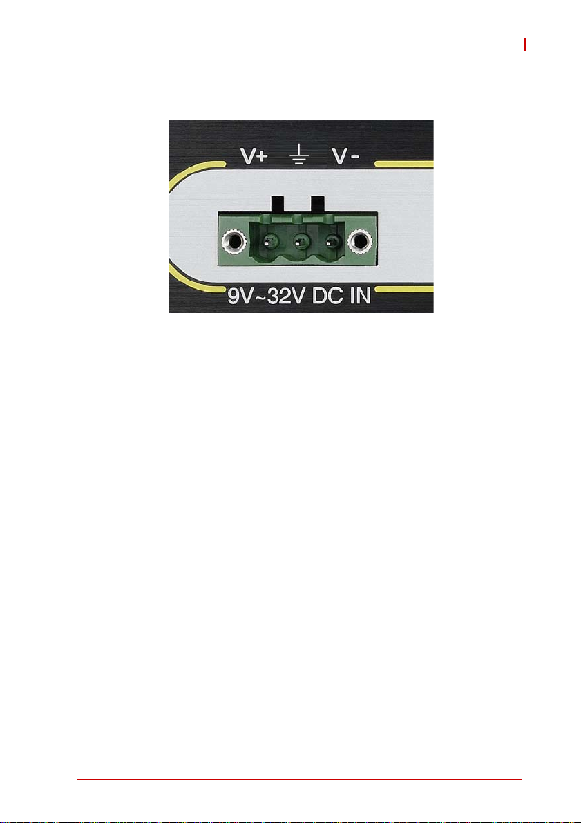
1.6.1 DC Power Supply Connector
Figure 1-12: DC Power Connector
The DC power supply connector of the EOS-4000, on the back
panel, consists of V-, chassis ground, and V+ pins, from right to
left. V+ and V- pins accept DC power input and the chassis ground
pin grounds the chassis for better EMC compatibility. The DC
power input of the EOS-4000 allows a voltage input range from 9
VDC to 32 VDC.
Introduction 15
Page 28

1.6.2 DB-62P COM Port Connector
The EOS-4000 provides four COM ports with DB-62P Connector
on the back panel, with cable connect to DB-62P connector to
extend four D-SUB 9-pin connectors, at COM1, COM2,
COM3,and COM4. COM1 & COM2 can support RS-232/ RS-422/
RS-485 modes based on BIOS settings, and COM3 and COM4
ports support only RS-232. Pin assignments are as follows.
PIN Signal Name PIN Signal Name
1 COM3_TXD 22 COM3_RXD 43 COM3_CTS#
2 COM3_DTR# 23 COM3_DSR# 44 COM3_RTS#
3 COM3_RI# 24 COM3_DCD# 45 GND
4 COM4_TXD 25 COM4_RXD 46 COM4_CTS#
5 COM4_DTR# 26 COM4_DSR# 47 COM4_RTS#
6 COM4_RI# 27 COM4_DCD# 48 GND
7 COM1_TXD 28 COM1_RXD 49 COM1_CTS#
8 COM1_DTR# 29 COM1_DSR# 50 COM1_RTS#
9 COM1_RI# 30 COM1_DCD# 51 GND
10 COM2_TXD 31 COM2_RXD 52 COM2_CTS#
11 COM2_DTR# 32 COM2_DSR# 53 COM2_RTS#
12 COM2_RI# 33 COM2_DCD# 54 GND
13-21 N/C 34-42 N/C 55-62 N/C
Table 1-10: DB-62P Connector Pin Assignment
PIN
Signal Name
16 Introduction
Page 29

EOS-4000
1.6.3 Trigger Input/Strobe Output Connector
The EOS-4000 features a 2-CH trigger input and strobe output on
the rear panel, based on an onboard digital I/O card supporting
features as follows.
Line/Area Trigger Input
Item Min. Max. Test Conditions
Input high threshold +2.0V +5.5V
Ambient temperature: 25°CInput low threshold 0V +0.8V
Input signal frequency N/A 2MHz
Strobe Output
Item Min. Max. Test Conditions
High output voltage +3.8V +5V
Low output voltage 0V +0.4V
Table 1-11: Trigger Input/Strobe Output Specifications
Typical output current: +/- 24mA
8
15
Figure 1-13: Trigger Input/Strobe Output Connector
Introduction 17
1
9
Page 30
Pin Name IN/OUT Description
1 Trigger 1 IN Line/area trigger (TTL) for CH1
2 Trigger 2 IN Line/area trigger (TTL) for CH2
3N/A
4N/A
5 Strobe 1 OUT Strobe output (TTL) for CH1
6 Strobe 2 OUT Strobe output (TTL) for CH2
7N/A
8N/A
9 +5V OUT +5V power source
10 GND N/A System digital ground
11 GND N/A System digital ground
12 GND N/A System digital ground
13 GND N/A System digital ground
14 GND N/A System digital ground
15 GND N/A System digital ground
Ta bl e 1-12: Trigger Input/Strobe Output Pin Defini tio ns
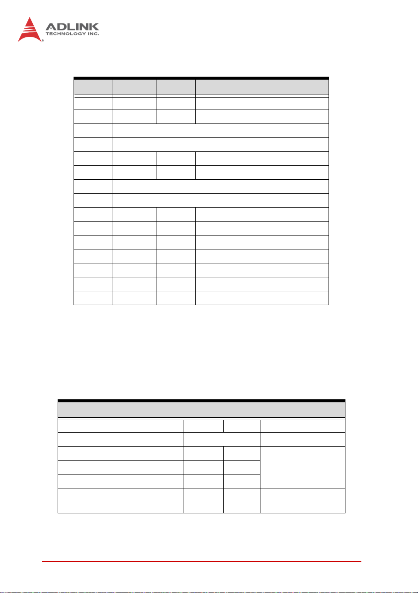
1.6.4 Encoder Input Port
The EOS-4000 features a 1-CH encoder input on the rear panel,
based on an onboard digital I/O card supporting features as fol-
lows.
Encoder Input
Item Min. Max. Test Conditions
Terminal resistor 100Ω
Input common mode voltage +/-7V
Positive input threshold +0.2V
Negative input low threshold -0.2V
Input signal frequency 10MHz
Table 1-13: Encoder Input Configurations
18 Introduction
Terminal resistor:
100Ω
Ambient
temperature=25°C
Page 31

EOS-4000
5
9
Figure 1-14: Encoder Input Port
Pin Name In/Out Description
1 EA+ IN Encoder trigger A+ (EIA-422)
2 EB+ IN Encoder trigger B+ (EIA-422)
3 EZ+ IN Encoder trigger Z+ (EIA-422)
4 GND N/A System digital ground
5 GND N/A System digital ground
6 EA- IN Encoder trigger A- (EIA-422)
7 EB- IN Encoder trigger B- (EIA-422)
8 EZ- IN Encoder trigger Z- (EIA-422)
9 GND -- System digital ground
1
6
T able 1-14: Encoder Input Port Pin Assignment
Introduction 19
Page 32

1.7 Internal I/O connectors
C
D
F
E
A
B
Figure 1-15: EOS-4000 Mainboard Top View
A Clear CMOS and ME RTC register jumpers
B DC 12 V fan connector
C DC 12 V fan connector (reserved)
D COM port connector (optional)
E USB 2.0 Type A connector
F SUMIT Connector
Table 1-15: Mainboard Connector Legend
20 Introduction
Page 33

EOS-4000
1.7.1 Clear CMOS and ME RTC Register Jumpers
When conditions occur under which the EOS-4000 controller fails
to boot, clearing stored BIOS content from CMOS and restoring
default settings may be required. To clear the CMOS, short pin#1
and pin#2 of JP1 and remove the jumper. CMOS restores to factory default settings
Normal Clear
As with JP1, shorting pin#1 and #2 of JP2 will clear the ME RTC
register, however, since this jumper is used by RMA, this is not
recommended, and may cause unexpected errors in system
behavior.
1.7.2 DC 12V Fan Connector
The EOS-4000 provides DC 12 V supply for fan module power.
The FAN module, inside the chassis, uses power directly from this
connector to exhaust heat, decreasing temperature of the system
for more stable operation.
1.7.3 DC 12V Fan Connector (reserved)
The EOS-4000 further reserves an additional DC 12 V supply connector for a second fan module. Like the first, the second module
is inside the chassis, and uses power directly from this connector
to exhaust heat, decreasing temperature of the system for more
stable operation.
1.7.4 USB 2.0 Type A Connector
A USB 2.0 Type A connector is provided to support expanded storage or security function through a dongle connection. The connector is deployed vertically, perpendicular to the board surface.
Introduction 21
Page 34

1.7.5 SUMIT Connector
SUMIT is a connection protocol that integrates common high-and
low-speed serial and legacy expansion buses for dedicated use. A
compact, stackable, multiboard I/O expansion solution, the SUMIT
connector supports one x1 PCI Express lane, one x4 PCI Express
lane, and additional power, ground and control signals. Pin defini-
tions are as follows.
Pin Description Pin Description
1 GND 27 PCIex4_TX2+
2 GND 28 PCIex4_RX2+
3 PCIex1_TX+ 29 PCIex4_TX2-
4 PCIex1_RX+ 30 PCIex4_RX2-
5 PCIex1_TX- 31 GND
6 PCIex1_RX- 32 GND
7 GND 33 PCIex4_TX3+
8 NC 34 PCIex4_RX3+
9 PCIex4_CLK+ 35 PCIex4_TX3-
10 PCIex1_CLK+ 36 PCIex4_RX3-
11 PCIex4_CLK- 37 GND
12 PCIex1_CLK- 38 GND
13 NC 39 PERST#
14 GND 40 WAKE#
15 PCIex4_TX0+ 41 +V12
16 PCIex4_RX0+ 42 +V12
17 PCIex4_TX0- 43 +V5
18 PCIex4_RX0- 44 +V12
19 GND 45 +V5
20 GND 46 +V3.3
21 PCIex4_TX1+ 47 +V5
22 PCIex4_RX1+ 48 +V3.3
23 PCIex4_TX1- 49 +V5
24 PCIex4_RX1- 50 +V3.3
25 GND 51 +V5
26 GND 52 +V5SB
Table 1-16: SUMIT Pin Definitions
22 Introduction
Page 35

EOS-4000
SATA
Figure 1-16: EOS-4000 Mainboard Underside View
1.7.6 SATA Connectors
The EOS-4000 provides two SATA connectors supporting data
transfer up to 6.0 Gb/s(600 MB/s). The SATA host controller supports legacy mode using I/O space and AHCI mode using memory
space.
The SATA connectors are compatible with 2.5 inch hard disk
(HDD) or solid state disk (SSD) drives, which must be installed to
the SATA connector with a HDD bracket.
Introduction 23
Page 36

1.8 General Purpose Digital Signals
1.8.1 General Purpose Digital Output (EDO)
In the common ground connection of isolated digital output, as
shown, when a “1” (logic high) is written by FPGA to a DO channel, the sink current passes through the transistors and the DO
channel goes low. When a “0” (logic low) is written by FPGA to a
DO channel, no current passes through the transistors and the DO
channel goes high. When the load is of an “inductance nature”
such as a relay, coil or motor, the Clamp COMn must be connected to an external power source. The extra connection is utilized for the ‘fly-wheel diode’ to form a current-release closed loop,
so that the transistors are protected from any high reverse voltage
generated by the inductance load when the output is switched
from high to low.
EOS-4000
24 Introduction
Clamp COMn
DOn
DC12V~24V
ISO GND
Page 37

1.8.2 General Purpose Digital Input (EDI)
The EOS-4000 provides 32 opto-isolated digital input channels on
the front panel. Circuitry of the isolated input channel is as follows.
DICOMn
Ri
DIn
As shown, signal connections for a supply and load connected to
an isolated input, here in the EOS-4000, can determine when a
load is powered. The load is connected to the power supply by a
switch and can be any DC voltage between 12 and 24 VDC. When
the switch is open, no current flows through the load and no voltage is applied to the load or to the EOS-4000 DI channels.
The digital logic of the EOS-4000 then registers a logic high for the
channel. When the switch is closed, current flows through the
diode and the EOS-4000 registers logic low for the channel.
Reducing DI channel Forward Current for High Voltage
EOS-4000
As input voltage exceeds 12 V, the input current drawn by the
EOS-4000 (forward current If) rises commensurately. At 24 V,
for example, current per line is determined by the formula:
(24V- 0.5V)/2.32k = 10.129 mA
To reduce the current and the power drawn, on a monitored circuit, for example, another resistor can be added in series with
the 2.32 kΩ current-limiting resistor, as shown.
Introduction 25
Page 38

EOS-4000
DICOMn
DC12V~24V
DIn
2.32k
It is recommended a resistance value be chosen allowing at
least 5 mA through the diode, assuming a maximum drop
across the diode of 0.5 V.
For example, for 24 V inputs a maximum resistance for Rs can
be found by the formula:
(24 V-0.5 V)/5 mA – 2.32k = 2.38k
26 Introduction
Page 39

2 Getting Started
This chapter describes accessing/changing memory modules,
hard disk drives, and the USB dongle in the system. Wallmounting is also described.
2.1 Unpacking Checklist
Before unpacking, check the shipping carton for any damage. If
the shipping carton and/or contents are damaged, inform your
dealer immediately. Retain the shipping carton and packing
materials for inspection. Obtain authorization from your dealer
before returning any product to ADLINK. Ensure that the following items are included in the package.
X EOS-4000 unit
X Wall mounting brackets (x2)
X Mounting M4, 8mm screws (x4)
X PS/2 Y cable
X Quick Start Guide
X ADLINK All-in-One DVD
EOS-1200
OEM versions with non-standard configuration, functionality, or
packaging may vary according to individual requirements.
NOTE:
NOTE:
X Always disconnect the power cord from the
chassis when working on the device, and do not
WARNING:
Getting Started 27
reconnect while the power switch is on, since
sudden power input can damage sensitive electronic components
X Only authorized and experienced electronics
personnel should open the chassis
X Always ground yourself to remove any static
electric charge before touching EOS, the device
is very sensitive to static electric charges; use a
grounding wrist strap at all times, and place all
electronic components on a static-dissipative
surface or in a static-shielded bag
Page 40

2.2 Installing Memory
1. Remove the three screws from the underside
2. Remove the underside cover
28 Getting Started
Page 41

EOS-1200
3. Insert the memory module into the DDR3 SO-DIMM at a
45° angle and press down until the memory module
snaps into place
Getting Started 29
Page 42

2.3 Installing a Hard Disk Drive
1. Remove all three screws from the underside
2. Remove the underside cover
30 Getting Started
Page 43

3. Remove the two screws fixing the hard drive carriage
EOS-1200
4. Slide the hard drive carriage out
Getting Started 31
Page 44
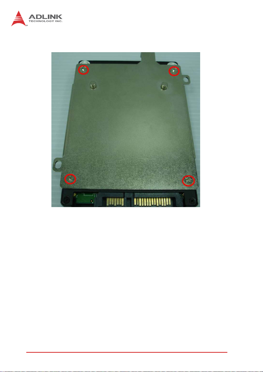
5. Secure the new hard drive to the hard drive carriage
32 Getting Started
Page 45

6. Slide the hard drive carriage in, until connection is
secured with the SATA power and data connectors
EOS-1200
7. Secure the hard drive carriage
Getting Started 33
Page 46

8. Replace the bottom cover and secure the three screws
2.4 Installing the USB Dongle
1. Loosen the thumbscrew
34 Getting Started
Page 47

2. Remove the top cover
EOS-1200
3. Plug the USB dongle into the USB port
Getting Started 35
Page 48

2.5 Installing Wallmount Brackets
Secure the walmount brackets in the four screwholes provided on
the underside of the chassis
36 Getting Started
Page 49

EOS-1200
2.6 Operating System Installation
The EOS-4000 is compatible with several operating systems for
maximum flexibility. Installation instructions for each follow. For
other OS support, please contact ADLINK for further information.
2.6.1 Windows 7
Installing AHCI on Windows 7
The AHCI driver must be enabled in the registry before SATA
mode of the boot drive can be changed, as follows:
1. Exit all Windows-based programs
2. In the Start menu, enter regedit in the Start Search box,
and select ENTER
3. If the User Account Control dialog box appears, select
Continue
4. Locate and select the registry subkey
HKEY_LOCAL_MACHINESystemCurrentControlSetS
ervicesMsahci
5. In the Name column of the right pane, right-click Start,
and select Modify
6. In the Value data box, enter 0 and select OK
7. In the File menu, select Exit to close the Registry Editor
8. Restart the computer, open the BIOS and enable AHCI.
At the next Windows login, the drivers for AHCI show as
intalled.
9. Restart a final time to complete the installation
Windows 7
Windows 7 supports EOS-4000 chipset drivers, allowing simple
installation. ADLINK also provides pre-installation services for
Windows 7 on the EOS-4000 (when the Windows XP license is
pre-purchased from ADLINK). For more information, please visit
the OS website
Getting Started 37
Page 50

Windows 7 Embedded Service Pack 1
Windows Embedded Standard 7 SP1 delivers the power, familiarity, and reliability of the Windows 7 operating system in a
componentized form, allowing developers to create advanced
commercial and consumer devices compatible with thousands
of existing Windows applications and drivers.
You can download the evaluation version from: http://
www.microsoft.com/download/en/details.aspx?id=11887
The download contains 3 DVD5 images (ISO's). Download the
.exe and .rar files for each DVD image into its own folder and
run the .exe file in that folder to reconstitute the .ISO file. Once
the .ISO file is created you can then burn the ISO onto a blank
DVD. The toolkit DVD is used to install the Image Configuration
Editor (ICE) and associated distribution share(s) onto a PC.
The 32-bit and 64-bit Standard 7 SP1 DVDs are bootable
WinPE DVDs that contain the Image Builder Wizard (IBW) and
the corresponding 32-bit or 64-bit distribution share. Typically
these DVDs are used to boot into Windows PE on the target
device and apply the runtime image created with ICE or to prototype image creation using the wizard and various templates
available in IBW.
Please read the Windows Embedded Standard 7 SP1 documentation for more information on using ICE and IBW to create
and deploy runtime images.
2.7 Driver Installation
After the OS is installed, all related drivers must be installed. This
section describes drivers needed for Windows operating systems
and installation procedures. For other OS support, please contact
ADLINK directly.
Once Windows is properly installed, the following installations are
required (most standard I/O device drivers have been included in
the Windows install):
1. Install the chipset driver
2. Install the graphics driver
3. Install the Ethernet driver
38 Getting Started
Page 51

EOS-1200
4. Install the USB3.0 driver
5. Install the ME (Management Engine Components) software
6. Install the Frame Grabber And Digital Input/Output Drivers
2.7.1 Chipset Driver Installation
The chipset driver directs the operating system to configure the
®
Intel
QM67 chipset, to ensure that the following features function
properly:
Z Core PCI and ISAPNP services
Z PCIe support
Z SATA storage support
Z USB support
Z Identification of Intel® Chipset components in the Device
Manager
To install the chipset driver:
1. Close any running applications
2. Execute Setup.exe and follow onscreen instructions
3. Reboot the system
2.7.2 Graphics Driver Installation
The EOS-4000 is equipped with the Intel® HD graphics family. To
install the graphics driver:
1. Close any running applications
2. Execute Setup.exe in the Graphics folder and follow the
onscreen instructions
3. Reboot the system
2.7.3 Ethernet Driver Installation
To install the driver for the Intel® 82574L/82579LM Gigabit network connection:
Getting Started 39
Page 52

1. Close any running applications
2. Execute Network.exe and follow onscreen instructions
3. Reboot the system
2.7.4 USB 3.0 Driver Installation
Please follow the following steps to install the Texas Instruments
USB 3.0 driver:
1. Close any running applications
2. Execute Texas Instruments xHCI Driver v1.12.25 (
WHQL - Multilanguage ).exe in the USB3 folder and follow the onscreen instructions to complete the setup
3. Reboot the system
2.7.5 ME (Management Engine Components) Software Installation
The Intel® Management Engine software components requiring
installation depend on the system's specific hardware and firmware features.
The installer detects system capabilities and installs the relevant
drivers and applications.
To install the ME Software:
1. Close any running applications
2. Execute Setup.exe in the ME_SW folder and follow the
onscreen instructions
2.7.6 Frame Grabber And Digital Input/Output Driver Installation
To install the drivers for ADLINK frame grabber and DI/O:
1. Close any running applications.
40 Getting Started
Page 53

EOS-1200
2. Execute PCMe-4432A-xxx.exe and follow the onscreen
instructions to complete the setup.
Microsoft .Net Framework 3.5 must be installed manually if the
OS is Windows 8, to ensure complete installation and proper
WARNING:
utility function.
The CamCreator utility automatically installs with the frame
grabber and digital I/O driver. For more information, please see
NOTE:
NOTE:
the CamCreator User’s Manual.
Following successful installation, the devices should appear in the
Device Manager, as shown
.
Getting Started 41
Page 54

This page intentionally left blank.
42 Getting Started
Page 55

Appendix A BIOS Setup
The Basic Input/Output System (BIOS) is a program that provides
a basic level of communication between the processor and
peripherals. In addition, the BIOS also contains codes for various
advanced features applied to the EOS-4000. The BIOS setup
program includes menus for configuring settings and enabling
features of the EOS-4000. Most users do not need to use the
BIOS setup program, as the EOS-4000 ships with default settings
that work well for most configurations.
In this section, BIOS configuration is described.
Changing BIOS settings may lead to incorrect controller
behavior and possible inability to boot. See “Clear
WARNING:
A.1 Main
CMOS and ME RTC Register Jumpers” on page 21.
EOS-4000
BIOS Setup 43
Page 56

A.1.1 System Time/System Date
This option changes the system time and date. Highlight System
Time or System Date using the up or down <Arrow> keys. Enter
new values using the keyboard then press <Enter> key. Press the
< Tab > key to move between fields. The date must be entered in
MM/DD/YY format. The time is entered in HH:MM:SS format.
The time is in 24-hour format. For example, 5:30 A.M.
appears as 05:30:00, and 5:30 P.M. as 17:30:00.
NOTE:
NOTE:
A.2 Advanced
Setting incorrect or conflicting values in Advanced BIOS
Setup may cause system malfunction
CAUTION:
44 BIOS Setup
Page 57

A.2.1 ACPI Settings
EOS-4000
Enable ACPI Auto Configuration
Enables or disables BIOS ACPI Auto Configuration.
Enable Hibernation
Enables or disables System ability to Hibernate. This option may
be not effective with some OS.
BIOS Setup 45
Page 58

A.2.2 CPU Configuration
Limit CPUID Maximum
Disabled for Windows XP
Execute Disable Bit
Enables XD to prevent certain classes of malicious buffer overflow attacks when combined with a supporting OS
Hardware Prefetcher
Enables or disables the Mid Level Cache(L2) streamer
prefetcher.
Adjacent Cache Line Prefetch
Enables or disables prefetching of adjacent cache lines.
46 BIOS Setup
Page 59

EOS-4000
Intel Virtualization Technology
When enabled, a VMM can utilize the additional hardware
capabilities provided by Vanderpool Technology
Local x2APIC
Enables Local x2APIC; some OS do not support this
EIST
Enables/Disables Intel SpeedStep Technology
Turbo Mode
Enables/Disables Intel TurboBoost Technology
C1E Function
When enabled, allows the CPU to enter enhanced C1 sleep
state to save more power than C1
CPU C3 Support
Enables/Disables CPU C3(ACPI C2) report to OS
CPU C6 Support
Enables/Disables CPU C6(ACPI C3) report to OS
CPU C7 Support
Enables/Disables CPU C7(ACPI C3) report to OS.
BIOS Setup 47
Page 60

A.2.3 Onboard Device Configuration
Intel 82579LM LAN
Enables/Disables onboard Intel 82579LM (built-in PCH) Lan
controller
Launch Intel 82579LM LAN PXE OpROM
Enables/Disables execution of LAN boot-rom to add boot
option for legacy network devices
Intel 82574 LAN
Enables/Disables onboard Intel 82574 Lan controller
Launch Intel 82574 LAN PXE OpROM
Enables/Disables execution of LAN boot-rom to add boot
option for legacy network devices
48 BIOS Setup
Page 61

A.2.4 Advanced Power Management
EOS-4000
Restore On AC Power Loss
Determines the state the computer enters when power is restored
after a power loss. Options are Last State, Power On and Power
Off.
Option Description
Power Off When set, powers the system down when
power is restored.
Power On When set, powers the system up when
power is restored.
Last State When set, powers the system up or down
depending on the last state when power is
restored.
Table A-1: Restore On Power Loss Options
BIOS Setup 49
Page 62
Wake up system by 82579L LAN in S5
Enables or disables integrated LAN to wake the system in S5
state.
RTC Wakeup in S5
Enables or disables system wake on alarm event.
System watchdog
Enables or disables system internal watchdog to prevent boot
failure at system POST stage.
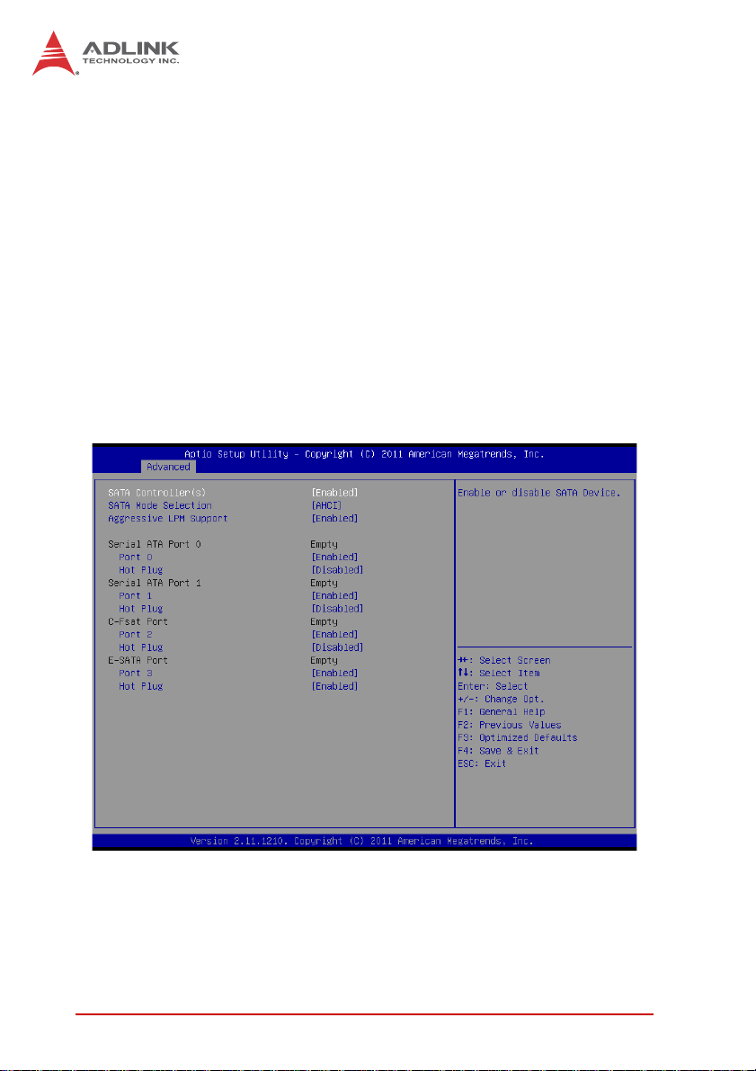
A.2.5 SATA Configuration
S-ATA Controller
Enables/ Disables Internal Serial ATA Controller 0.
SATA Mode
50 BIOS Setup
Page 63

EOS-4000
This option selects the SATA channel configuration from (1) IDE
Mode (2) AHCI Mode or (3) RAID Mode.
Serial ATA Port 0~1, C-Fast Port, and E-SATA Port.
Port X
Enables or Disables SATA Port X
Hot Plug
Sets this port as hot pluggable.
A.2.6 Intel Anti-Theft Technology Configuration
Intel Anti-Theft Technology
Enables or disables Intel AT function. Intel
®
Anti-Theft Technology helps stop theft by rendering computers useless with
immediate shutdown
BIOS Setup 51
Page 64

Intel Anti-Theft Technology Recovery/Enter Intel AT Suspend
Mode
Miscellaneous settings for Intel AT function
A.2.7 AMT Configuration
Intel AMT Setup Prompt
Enables or disables MEBx launch during system post for configuring AMT features
BIOS Hotkey Pressed/MEBx Selection Screen
Miscellaneous settings for iAMT function
52 BIOS Setup
Page 65

A.2.8 USB Configuration
EOS-4000
Legacy USB Support
Enables Legacy USB Support. AUTO option disables legacy
support if no USB devices are connected. DISABLE option will
keep USB devices available only for EFI applications.
USB3.0 Support
Enables or disables USB3.0 (XHCI) controller support, allowing
USB 3.0 devices to be used in DOS environment
XHCI Hand-Off
Enables BIOS support for XHCI Hands-Off feature. The default
option is Enabled.
BIOS Setup 53
Page 66

EHCI Hand-Off
Enables BIOS support on EHCI Hands-Off feature. The default
option is Enabled.
A.2.9 Super I/O Configuration
Serial Port 1 to 4 Configuration/Serial Port 5 Configuration
(Valid when PCB is changed)
Options in this configuration can enable/disable the port, select
a port type (RS-232/422/485) for Serial Port 1 and 2 only, or
change the port settings (address)
54 BIOS Setup
Page 67

EOS-4000
A.2.10 Hardware Monitor
PC Health Status
Hardware health on Super I/O monitors Board Temperature 1/
2, CPU Temperature, CPU Voltage, I-GFX Voltage, VCCSA
Voltage, +1.05V, +3.3V, +1.5V, +5V, +12.0V, VBAT, and Fan1/2
Speed.
Smart Fan 1/2 Mode
Sets the fan policy, supporting “Full on Mode”, in which the system fan (1/2) runs at full speed, “Manual Mode”, providing manual control of fan speed, and “Automatic Mode”, which controls
the system fan (1/2) according to a given fan policy
BIOS Setup 55
Page 68

A.2.11 Serial Port Console Redirection
COM 1 to 4, SOL (Serial Over LAN) COM
Console Redirection
Enables Console Redirection function on COM 1 to 4, SOL
COM
Console Redirection Settings
Sets miscellaneous parameters for COM Port 1 to 4, SOL
COM
A.2.12 Serial Port for Out-of-Band Management/EMS
Console Redirection
Enables Console Redirection function for remote management
of a Windows Server OS, via the port selected by Out-of-Band
Mgmt Port
56 BIOS Setup
Page 69

Out-of-Band Mgmt Port
Selects the COM Port for remote management of a Windows
OS
Terminal Type
Selects the transmission protocol for remote terminal console
A.3 Chipset
EOS-4000
BIOS Setup 57
Page 70

A.3.1 System Agent (SA) Configuration
VT-d
Enables VT-d function for efficient virtualization of I/O devices
Graphics Configuration
Selects the internal graphic device shared memory size and
power policy
58 BIOS Setup
Page 71

EOS-4000
Graphics Turbo IMON Current
Sets the maximum IMON current value for graphics turbo
mode
GTT Size
Selects the GTT size for internal graphics
DVMT Pre-Allocated
Selects DVMT 5.0 pre-allocated graphics memory size used by
the internal graphics device
DVMT Total Gfx Memory
Selects DVMT 5.0 total graphics memory size used by the
internal graphics device
BIOS Setup 59
Page 72

A.4 Boot
A.4.1 Boot Configuration
Setup Prompt Timeout
Number of seconds to wait for setup activation key (“DEL”)
Bootup NumLock State
Allows/disallows the NumLock setting to be modified during
boot
60 BIOS Setup
Page 73

EOS-4000
Quiet Boot
Option Description
Disabled Directs BIOS to display the POST messages
Enabled Directs BIOS to display the OEM logo
A.4.2 Boot Option Priorities
Specifies the priority of boot devices. All installed boot devices are
detected during POST and displayed
A.5 Security
If only the Administrator’s password is set, then only access to
Setup is limited and requested only when entering Setup. If only
the user’s password is set, then this is a power-on password and
BIOS Setup 61
Page 74

must be entered to boot or enter setup. In Setup the user will have
Administrator rights.
Administrator Password
Set Administrator password for setup
User Password
Set boot/setup User password
A.6 Exit
Save Changes and Exit
When BIOS settings are complete, select this option to save all
changes and reboot the system for the new settings to take effect.
Discard Changes and Exit
Select this option to discard all changes and exit BIOS setup.
62 BIOS Setup
Page 75

EOS-4000
Discard Changes and Reset
Resets system setup without saving any changes.
Restore Defaults
Select this option to set all BIOS options to default settings. The
Default setting is designed for maximum system stability, but not
maximum performance. Select the Restore Defaults Setup options
if the computer encounters system configuration problems.
Launch EFI Shell from Filesystem Device
Attempts to launch EFI Shell application (Shellx64.efi) from one of
the available file system devices.
BIOS Setup 63
Page 76

This page intentionally left blank.
64 BIOS Setup
Page 77

EOS-4000
Important Safety Instructions
For user safety, please read and follow all instructions,
WARNINGS, CAUTIONS, and NOTES marked in this manual
and on the associated equipment before handling/operating the
equipment.
X Read these safety instructions carefully.
X Keep this user’s manual for future reference.
X Read the specifications section of this manual for detailed
information on the operating environment of this equipment.
X When installing/mounting or uninstalling/removing
equipment:
Z Turn off power and unplug any power cords/cables.
X To avoid electrical shock and/or damage to equipment:
Z Keep equipment away from water or liquid sources;
Z Keep equipment away from high heat or high humidity;
Z Keep equipment properly ventilated (do not block or
cover ventilation openings);
Z Make sure to use recommended voltage and power
source settings;
Z Always install and operate equipment near an easily
accessible electrical socket-outlet;
Z Secure the power cord (do not place any object on/over
the power cord);
Z Only install/attach and operate equipment on stable
surfaces and/or recommended mountings; and,
Z If the equipment will not be used for long periods of time,
turn off and unplug the equipment from its power source.
Important Safety Instructions 65
Page 78

X Never attempt to fix the equipment. Equipment should only
be serviced by qualified personnel.
A Lithium-type battery may be provided for uninterrupted, backup
or emergency power.
Risk of explosion if battery is replaced with one of an incorrect
type. Dispose of used batteries appropriately.
WARNING:
X Equipment must be serviced by authorized technicians
when:
Z The power cord or plug is damaged;
Z Liquid has penetrated the equipment;
Z It has been exposed to high humidity/moisture;
Z It is not functioning or does not function according to the
user’s manual;
Z It has been dropped and/or damaged; and/or,
Z It has an obvious sign of breakage.
66 Important Safety Instructions
Page 79

Getting Service
Contact us should you require any service or assistance.
ADLINK Technology, Inc.
Address: 9F, No.166 Jian Yi Road, Zhonghe District
New Taipei City 235, Taiwan
ᄅקؑխࡉ৬ԫሁ 166 ᇆ 9 ᑔ
Tel: +886-2-8226-5877
Fax: +886-2-8226-5717
Email: service@adlinktech.com
Ampro ADLINK Technology, Inc.
Address: 5215 Hellyer Avenue, #110, San Jose, CA 95138, USA
Tel: +1-408-360-0200
Toll Free: +1-800-966-5200 (USA only)
Fax: +1-408-360-0222
Email: info@adlinktech.com
ADLINK Technology (China) Co., Ltd.
Address: Ϟ⍋Ꮦ⌺ϰᮄᓴ∳催⾥ᡔು㢇䏃 300 ো(201203)
300 Fang Chun Rd., Zhangjiang Hi-Tech Park,
Pudong New Area, Shanghai, 201203 China
Tel: +86-21-5132-8988
Fax: +86-21-5132-3588
Email: market@adlinktech.com
ADLINK Technology Beijing
Address: ࣫ҀᏖ⍋⎔Ϟഄϰ䏃 1 োⲜ߯ࡼ E ᑻ 801 ᅸ(100085)
Rm. 801, Power Creative E, No. 1,
Shang Di East Rd., Beijing, 100085 China
Tel: +86-10-5885-8666
Fax: +86-10-5885-8626
Email: market@adlinktech.com
EOS-4000
ADLINK Technology Shenzhen
Address: ⏅ഇᏖቅ⾥ᡔು催ᮄϗ䘧᭄ᄫᡔᴃು
Tel: +86-755-2643-4858
Fax: +86-755-2664-6353
Email: market@adlinktech.com
LiPPERT ADLINK Technology GmbH
Address: Hans-Thoma-Strasse 11, D-68163, Mannheim, Germany
Tel: +49-621-43214-0
Fax: +49-621 43214-30
Email: emea@adlinktech.com
A1 2 ὐ C (518057)
2F, C Block, Bldg. A1, Cyber-Tech Zone, Gao Xin Ave. Sec. 7,
High-Tech Industrial Park S., Shenzhen, 518054 China
Getting Service 67
Page 80

ADLINK Technology, Inc. (French Liaison Office)
Address: 15 rue Emile Baudot, 91300 Massy CEDEX, France
Tel: +33 (0) 1 60 12 35 66
Fax: +33 (0) 1 60 12 35 66
Email: france@adlinktech.com
ADLINK Technology Japan Corporation
Address: ͱ101-0045 ᵅҀ䛑ҷ⬄⼲⬄䤯ފ⬎ 3-7-4
Tel: +81-3-4455-3722
Fax: +81-3-5209-6013
Email: japan@adlinktech.com
ADLINK Technology, Inc. (Korean Liaison Office)
Address: 昢殾柢 昢爎割 昢爎壟 1675-12 微汾瘶捒娯 8猻
Tel: +82-2-2057-0565
Fax: +82-2-2057-0563
Email: korea@adlinktech.com
ADLINK Technology Singapore Pte. Ltd.
Address: 84 Genting Lane #07-02A, Cityneon Design Centre,
Tel: +65-6844-2261
Fax: +65-6844-2263
Email: singapore@adlinktech.com
ADLINK Technology Singapore Pte. Ltd. (Indian Liaison Office)
Address: 1st Floor, #50-56 (Between 16th/17th Cross) Margosa Plaza,
Tel: +91-80-65605817, +91-80-42246107
Fax: +91-80-23464606
Email: india@adlinktech.com
⼲⬄ 374 ɛɳ 4F
KANDA374 Bldg. 4F, 3-7-4 Kanda Kajicho,
Chiyoda-ku, Tokyo 101-0045, Japan
8F Mointer B/D,1675-12, Seocho-Dong, Seocho-Gu,
Seoul 137-070, Korea
Singapore 349584
Margosa Main Road, Malleswaram, Bangalore-560055, India
ADLINK Technology, Inc. (Israeli Liaison Office)
Address: 6 Hasadna St., Kfar Saba 44424, Israel
Tel: +972-9-7446541
Fax: +972-9-7446542
Email: israel@adlinktech.com
68 Getting Service
 Loading...