

Page 1
EOS-1200
4-CH Gigabit PoE Embedded Vision System
User’s Manual
Manual Rev.: 3.00
Revision Date: March 27, 2013
Part No: 50-1Z111-1010
Advance Technologies; Automate the World.
Page 2

Revision History
Revision Release Date Description of Change(s)
2.00 Dec. 28, 2011 Initial release
New device release
Function Library errata
3.00 Mar. 27,2013
rectified
Organizational structure
updated
ii
Page 3

EOS-1200
Preface
Copyright 2013 ADLINK Technology Inc.
This document contains proprietary information protected by copyright. All rights are reserved. No part of this manual may be reproduced by any mechanical, electronic, or other means in any form
without prior written permission of the manufacturer.
Disclaimer
The information in this document is subject to change without prior
notice in order to improve reliability, design, and function and does
not represent a commitment on the part of the manufacturer.
In no event will the manufacturer be liable for direct, indirect, special, incidental, or consequential damages arising out of the use or
inability to use the product or documentation, even if advised of
the possibility of such damages.
Environmental Responsibility
ADLINK is committed to fulfill its social responsibility to global
environmental preservation through compliance with the European Union's Restriction of Hazardous Substances (RoHS) directive and Waste Electrical and Electronic Equipment (WEEE)
directive. Environmental protection is a top priority for ADLINK.
We have enforced measures to ensure that our products, manufacturing processes, components, and raw materials have as little
impact on the environment as possible. When products are at their
end of life, our customers are encouraged to dispose of them in
accordance with the product disposal and/or recovery programs
prescribed by their nation or company.
Trademarks
Product names mentioned herein are used for identification purposes only and may be trademarks and/or registered trademarks
of their respective companies.
Preface iii
Page 4
Conventions
Take note of the following conventions used throughout this
manual to make sure that users perform certain tasks and
instructions properly.
Additional information, aids, and tips that help users perform
tasks.
NOTE:
NOTE:
Information to prevent minor physical injury, component dam-
age, data loss, and/or program corruption when trying to com-
CAUTION:
WARNING:
plete a task.
Information to prevent serious physical injury, component
damage, data loss, and/or program corruption when trying to
complete a specific task.
iv Preface
Page 5

EOS-1200
Table of Contents
Revision History...................................................................... ii
Preface.................................................................................... iii
List of Figures........................................................................ ix
List of Tables.......................................................................... xi
1 Introduction ........................................................................ 1
1.1 Overview.............................................................................. 1
1.2 Features............................................................................... 1
1.3 Specifications....................................................................... 2
1.4 Unpacking Checklist ............................................................ 4
1.5 Schematics .......................................................................... 5
1.6 Front Panel I/O Connectors................................................. 7
1.6.1 LED Indicators ............................................................ 8
1.6.2 Power Switch.............................................................. 8
1.6.3 Reset Button............................................................... 8
1.6.4 PS/2 Connector .......................................................... 8
1.6.5 Dual Gigabit Ethernet Ports........................................ 9
1.6.6 DVI-I connector......................................................... 10
1.6.7 USB 2.0 Connectors................................................. 11
1.6.8 USB 3.0 Connectors................................................. 11
1.6.9 CFast Slot................................................................. 12
1.6.10 PoE (Power over Ethernet) Ports ............................. 12
1.7 Rear Panel I/O Connectors................................................ 13
1.7.1 DC Power Supply Connector.................................... 14
1.7.2 Audio Jacks .............................................................. 14
1.7.3 DB-62P COM Port Connector .................................. 15
1.7.4 Rear Panel Digital I/O............................................... 16
1.8 Internal I/O connectors ...................................................... 18
Table of Contents v
Page 6

1.8.1 Clear CMOS and ME RTC Register Jumpers .......... 19
1.8.2 DC 12V Fan Connector ............................................ 19
1.8.3 DC 12V Fan Connector (reserved) ........................... 19
1.8.4 USB 2.0 Type A Connector ...................................... 19
1.8.5 SUMIT Connector ..................................................... 20
1.8.6 SATA Connectors ..................................................... 21
1.9 General Purpose Digital Signals........................................ 22
1.9.1 General Purpose Digital Output (EDO)..................... 22
1.9.2 General Purpose Digital Input (EDI) ......................... 23
2 Getting Started.................................................................. 27
2.1 Installing Memory............................................................... 27
2.2 Installing a Hard Disk Drive (HDD) .................................... 28
2.3 Installing the USB Dongle.................................................. 29
2.4 Installing Wall-Mount Brackets........................................... 30
2.5 Operating System Installation............................................ 30
2.5.1 Windows XP ............................................................. 31
2.5.2 Windows 7 ................................................................ 33
2.6 Driver Installation ............................................................... 35
2.6.1 Chipset Driver Installation......................................... 35
2.6.2 Graphics Driver Installation....................................... 36
2.6.3 Ethernet Driver Installation ....................................... 36
2.6.4 Audio Driver Installation............................................ 36
2.6.5 USB 3.0 Driver Installation........................................ 36
2.6.6 ME (Management Engine Components)
Software Installation ................................................. 37
2.6.7 Digital Input/ Output Driver Installation ..................... 37
A Appendix: Function Library..............................................39
A.1 List of Functions................................................................. 39
A.2 Data Types......................................................................... 40
A.3 Setting Up the Build Environment ...................................... 40
vi Table of Contents
Page 7

EOS-1200
A.1.1 Include Files ............................................................. 40
A.1.2 Library Files .............................................................. 41
A.1.3 DLL Files .................................................................. 41
A.2 System & Initialization Functions ....................................... 42
A.1.1 Register_Card .......................................................... 42
A.1.2 Release_Card........................................................... 43
A.1.3 GetBaseAddr ............................................................ 44
A.1.4 GetCardIndexFromID ............................................... 45
A.1.5 GetCardType ............................................................ 46
A.1.6 GetLCRAddr ............................................................. 47
A.2 DI/O Functions ................................................................... 48
A.1.1 DI_ReadLine............................................................. 48
A.1.2 DI_ReadPort............................................................. 49
A.1.3 DO_ReadLine........................................................... 50
A.1.4 DO_WriteLine ........................................................... 52
A.1.5 DO_ReadPort ........................................................... 53
A.1.6 DO_WritePort ........................................................... 54
A.2 COS Interrupt Functions .................................................... 55
A.1.1 DIO_INT_Event_Message........................................ 55
A.1.2 DIO_INT1_EventMessage........................................ 57
A.1.3 DIO_INT2_EventMessage........................................ 59
A.1.4 DIO_SetDualInterrupt ............................................... 60
A.1.5 DIO_SetCOSInterrupt32........................................... 62
A.1.6 DIO_GetCOSLatchData32 ....................................... 63
A.2 Smart PoE Functions ......................................................... 65
A.1.1 SmartPoE_SetPower................................................ 65
A.2 EEPROM Functions........................................................... 66
A.1.1 EEPROM_ReadByte ................................................ 66
A.1.2 EEPROM_WriteByte ................................................ 67
A.1.3 EEPROM_WriteBytes............................................... 68
B Appendix: BIOS Setup......................................................71
Table of Contents vii
Page 8

B.1 Main ................................................................................... 71
B.1.1 System Time/System Date ....................................... 72
B.2 Advanced ........................................................................... 72
B.2.1 ACPI Settings ........................................................... 73
B.2.2 CPU Configuration.................................................... 74
B.2.3 Onboard Device Configuration ................................. 76
B.2.4 Advanced Power Management................................. 77
B.2.5 SATA Configuration.................................................. 78
B.2.6 Intel Anti-Theft Technology Configuration ................79
B.2.7 AMT Configuration.................................................... 80
B.2.8 USB Configuration .................................................... 81
B.2.9 Super I/O Configuration ............................................ 82
B.2.10 Hardware Monitor ..................................................... 83
B.2.11 Serial Port Console Redirection................................ 84
B.2.12 Serial Port for Out-of-Band Management/EMS ........84
B.3 Chipset............................................................................... 85
B.3.1 System Agent (SA) Configuration............................. 86
B.4 Boot ................................................................................... 88
B.4.1 Boot Configuration.................................................... 88
B.4.2 Boot Option Priorities................................................ 89
B.5 Security .............................................................................. 89
B.6 Exit ..................................................................................... 90
Important Safety Instructions............................................... 93
Getting Service...................................................................... 95
viii Table of Contents
Page 9

EOS-1200
List of Figures
Figure 1-1: EOS-1200 Front View...................................................... 5
Figure 1-2: EOS-1200 Rear View ...................................................... 5
Figure 1-3: EOS-1200 Top View ........................................................ 6
Figure 1-4: EOS-1200 Right Side View.............................................. 6
Figure 1-5: EOS-1200 Left Side View ................................................ 7
Figure 1-6: Front Panel I/O Connectors ............................................. 7
Figure 1-7: Gigabit Ethernet Ports ................................................... 10
Figure 1-8: DVI-I connector.............................................................. 10
Figure 1-9: PoE Port Connections ................................................... 12
Figure 1-10: Rear Panel I/O Connectors............................................ 14
Figure 1-11: DC Power Connector..................................................... 14
Figure 1-12: EOS-1200 Mainboard Top View .................................... 18
Figure 1-13: EOS-1200 Mainboard Underside View.......................... 21
List of Figures ix
Page 10

This page intentionally left blank.
xList of Figures
Page 11

EOS-1200
List of Tables
Table 1-1: EOS-1200 General Specifications ................................... 2
Table 1-2: Front Panel I/O Connector Legend.................................. 7
Table 1-3: LED Indicators ................................................................. 8
Table 1-4: Gigabit Ethernet Port Features ........................................ 9
Table 1-5: Active/Link LED ............................................................. 10
Table 1-6: Speed LED .................................................................... 10
Table 1-7: DVI-I Connector Signals ................................................ 11
Table 1-8: PoE Port Connections Legend ...................................... 13
Table 1-9: Rear Panel I/O Connector Legend ................................ 14
Table 1-10: DB-62P Connector Pin Assignment............................... 15
Table 1-11: Rear Panel Digital I/O Pin Definitions ............................ 17
Table 1-12: Rear Panel Digital I/O Pin Legend................................. 17
Table 1-13: Mainboard Connector Legend ....................................... 18
Table 1-14: SUMIT Pin Definitions.................................................... 21
Table B-1: Restore On Power Loss Options ................................... 77
List of Tables xi
Page 12

This page intentionally left blank.
xii List of Tables
Page 13

1 Introduction
1.1 Overview
ADLINK’s EOS-1200 is a rugged embedded vision system that
features four independent Gigabit PoE (power over Ethernet)
ports in a compact 220mm (W) x 80 mm (H) x 200 mm (D) small
form factor chassis, with 2nd and 3rd Generation Intel
i5/i7 processors providing ample power to manage demanding
multicamera high resolution machine vision applications, such as
robot guidance and 3D machine vision.
The EOS-1200 supports rich I/O, including 4 RS-232/422/485, 4
USB 2.0, 2 USB 3.0, and 32 isolation digital I/O input, and dual
storage support (two SATA and one CFAST slots). An internal
USB port and 1 kbit Programmable EEPROM make the system
friendly to integrate, deploy, and manage copy protection or software license authentication.
With long-life embedded components and incorporated system
monitoring components to monitor CPU temperature, fan speed,
and system responsiveness, the EOS-1200 provides a notably
robust and reliable platform for mission critical applications.
®
EOS-1200
Core™
1.2 Features
X 230W X 206D X 82H mm (9.06 X 8.11 X 3.23 in), compact and
rugged system design
X 2nd and 3rd Generation Intel
X Up to 4 gigabit PoE (power over Ethernet) multi-camera
support
X Internal USB port and 1 Kbit Programmable EEPROM
X IEEE-1588 (Precise Time Protocol) compliant for multi-cam-
era synchronization
X Supports two SATA ports and one CFast slot
Introduction 1
®
Core™ i5/i7 processors
Page 14

1.3 Specifications
General Specifications
System Core
Processor Intel® Core ™ i5 2.5GHz, i7 2.1GHz, or i7 2.3GHz
®
Chipset Intel
Video
Memory
Camera Interface
GigE Vision
I/O Interface
DI/O 16 DI/O in rear panel, DSUB37 female
Ethernet
Serial Port
USB
Audio 1x Mic-in and 1x Speaker-out
KB/MS
Power Supply
DC Input
AC Input Optional 150 W external AC-DC adapter
QM6 Express
VGA+DVI-D output by DVI-I connector- analog CRT,
supports QXGA, 2048 x 1536 resolution
2 socket slot for DDR3 1066/1333/1600 MHz
SODIMM module (Max. capacity 8GB)
4-CH Gigabit PoE (power over Ethernet)
IEEE 802.3af compliant, total max. power output
32W
2x GbE port (1x Intel® 82574L, 1x Intel®
82579LM(PHY)) with WOL function on each port
2x software-programmable RS-232/422/485 (COM1
& COM2)
2x RS-232 (COM3 & COM4)
4x USB 2.0 ports
2x USB 3.0 ports
1x PS/2 for keyboard and mouse (requires S3
wakeup)
Built-in 9-32 VDC wide-range DC 3P pluggable
connector with latch (GND, V-, V+)
Security
Table 1-1: EOS-1200 General Specifications
2Introduction
Page 15

EOS-1200
General Specifications
USB
ID 1kBit EEPROM
Storage
SATA HDD
CFast 1x CFast slot, SATA 3Gb/s compatible
Mechanical
Dimensions 230W X 206D X 82H mm (9.06 X 8.11 X 3.23 in)
Weight 3 kg (6.61 lb)
Mounting Wall- and rail-mount kit
OS
Operating system
Environmental
Operating
temperature
Storage
temperature
Humidity Approx. 95% @ 40° C (non-condensing)
1x internal USB port supporting installation of a USB
dongle for security function.
2x SATA port for 2.5" HDD/SSD installation
RAID 0/1/5/10
Windows XP/XP Embedded
Windows 7/7 Embedded
0° to 55° C (32 to 131° F)
-40° to 85° C (-40 to 185° F) (excl. HDD/SDD/CFast)
CFast
Vibration
(Operating)
Shock
EMI CE, FCC Class A
Table 1-1: EOS-1200 General Specifications
Introduction 3
SSD
HDD
Operating, 30 Grms, half sine 11ms duration
(CF or SSD)
5 Grms, 5-500 Hz, 3 axes
3 Grms, 5-500 Hz, 3 axes
0.5 Grms, 5-500 Hz, 3 axes
Page 16

X Always disconnect the power cord from the
chassis when working on the device, and do not
reconnect while the power switch is on, since
sudden power input can damage sensitive electronic components
X Only authorized and experienced electronics
personnel should open the chassis
X Always ground yourself to remove any static
electric charge before touching EOS, the device
is very sensitive to static electric charges; use a
grounding wrist strap at all times, and place all
electronic components on a static-dissipative
surface or in a static-shielded bag
1.4 Unpacking Checklist
Before unpacking, check the shipping carton for any damage. If
the shipping carton and/or contents are damaged, inform your
dealer immediately. Retain the shipping carton and packing
materials for inspection. Obtain authorization from your dealer
before returning any product to ADLINK. Ensure that the following items are included in the package.
X EOS-1200 unit
X Wall mounting brackets (x2)
X Mounting M4, 8mm screws (x4)
X PS/2 Y cable
X Gigabit PoE covers (x4)
X USB dongle mounting bracket
X User’s manual
X ADLINK All-in-One DVD
OEM versions with non-standard configuration, functionality, or
packaging may vary according to individual requirements.
NOTE:
NOTE:
4Introduction
Page 17
1.5 Schematics
All units are in millimeters (mm)
NOTE:
NOTE:
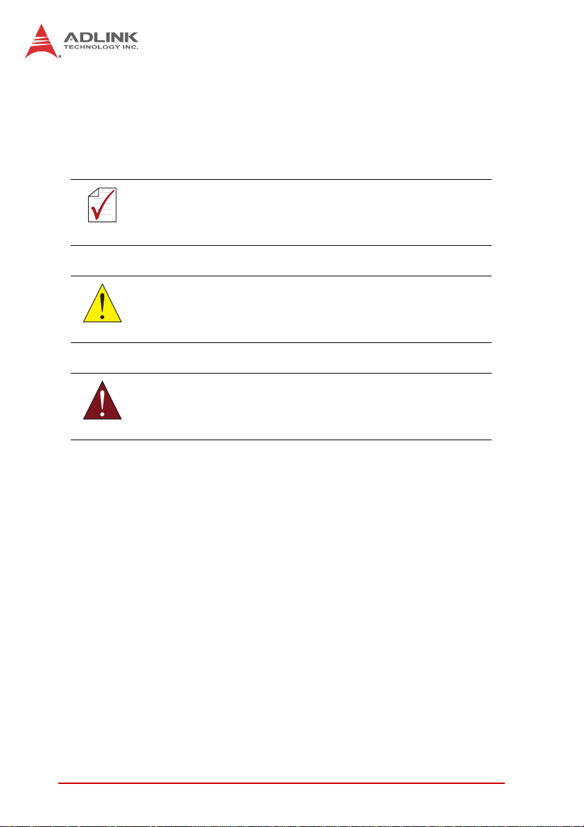
Figure 1-1: EOS-1200 Front View
EOS-1200
82
230
Figure 1-2: EOS-1200 Rear View
Introduction 5
Page 18
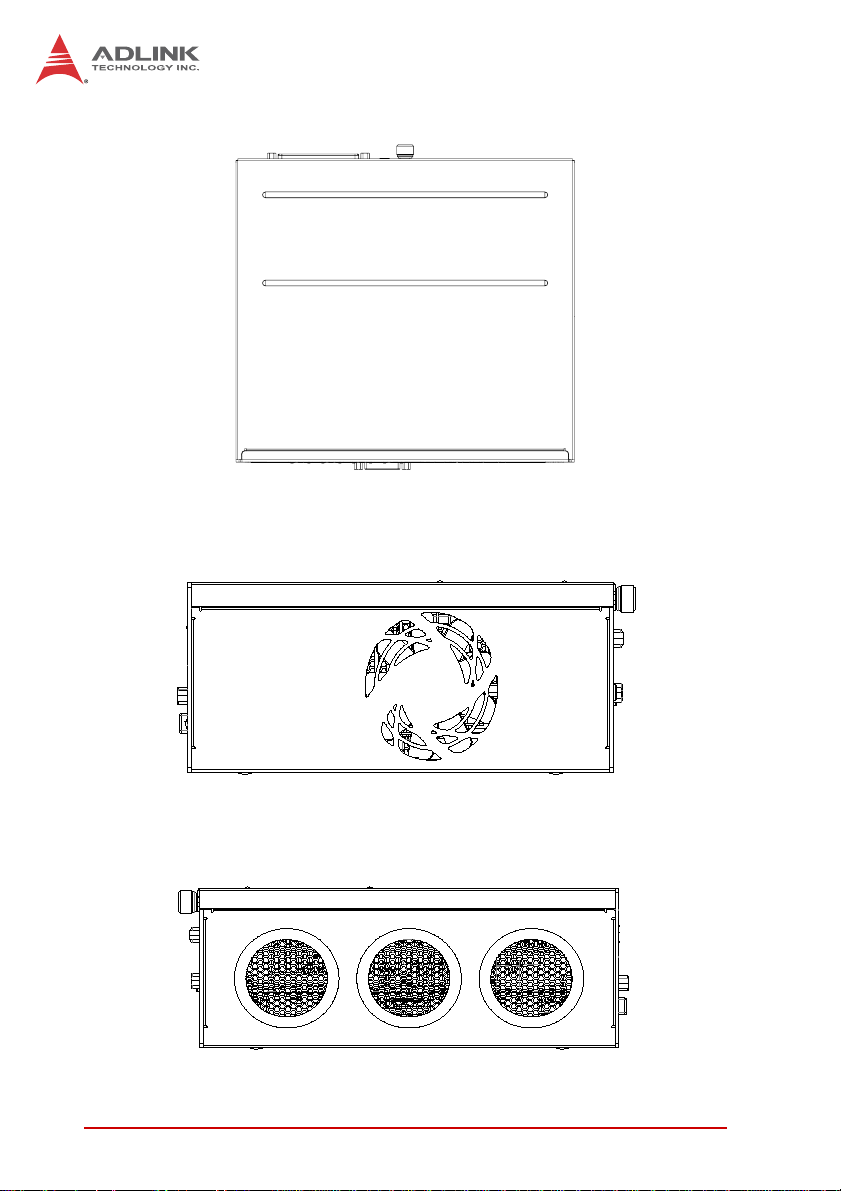
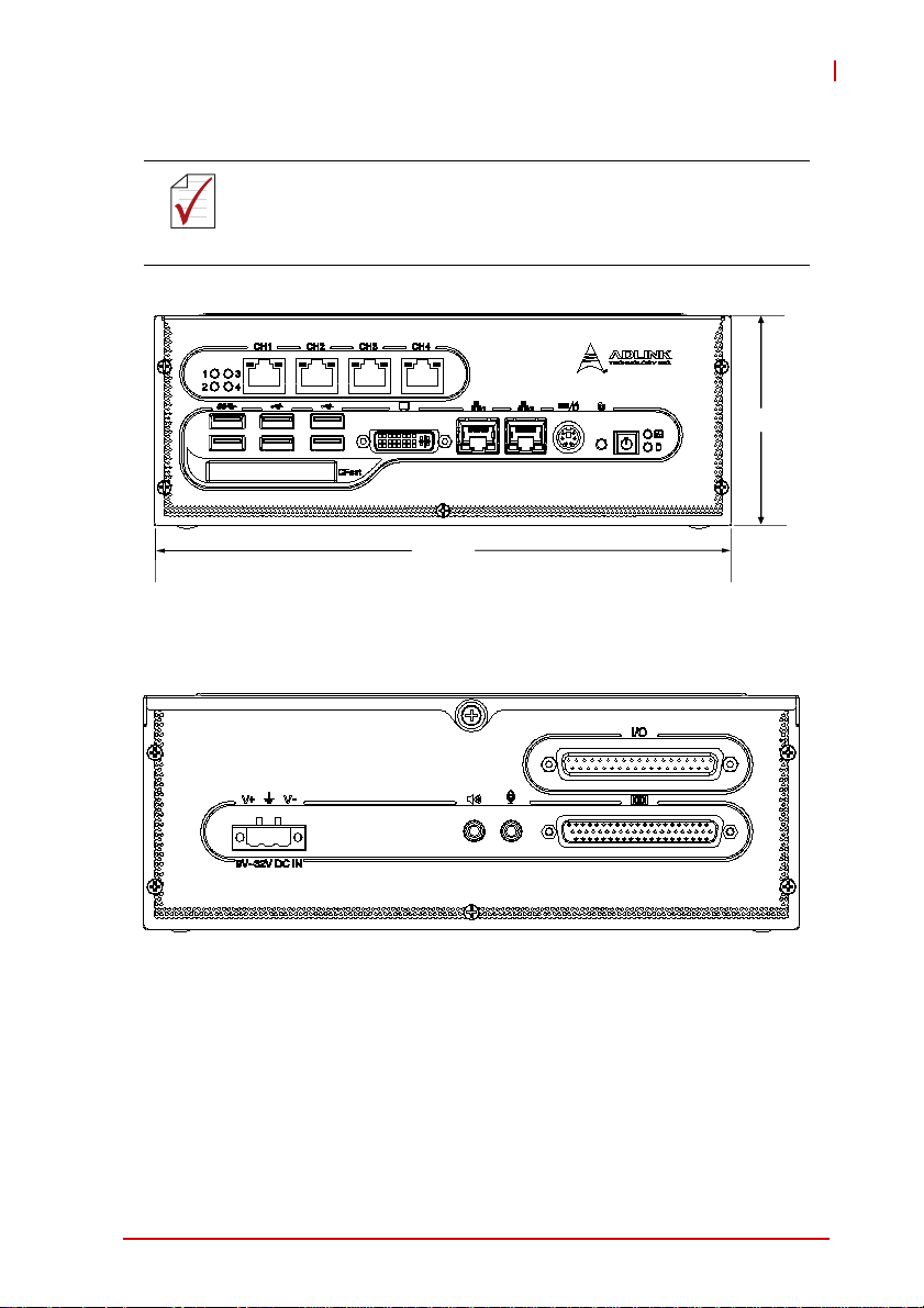
Figure 1-3: EOS-1200 Top View
Figure 1-4: EOS-1200 Right Side View
6Introduction
Page 19
EOS-1200
Figure 1-5: EOS-1200 Left Side View
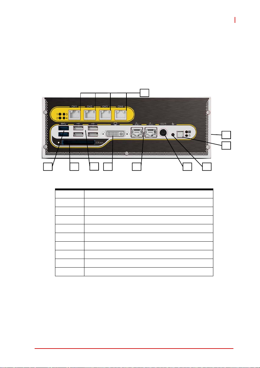
1.6 Front Panel I/O Connectors
The EOS-1200 provides I/O connection on the front panel, as follows.
A
B
HI
Figure 1-6: Front Panel I/O Connectors
A LED indicators
B Power switch
C Reset switch
D PS/2 keyboard & mouse
E Dual Gigabit Ethernet ports
F DVI-I connector
G USB 2.0 connectors x4 (Type A)
H USB3.0 connector (Type A) x2
I CFast connector(Push-Push,Type II)
J 4-CH PoE Connectors
Table 1-2: Front Panel I/O Connector Legend
EFG
D
C
Introduction 7
Page 20

1.6.1 LED Indicators
In addition to the LED of the power switch, two LEDs on the front
panel indicate the following.
LED indicator Color Description
X If lit continuously, indicates no
physical storage is connected
Diagnostic Yellow
X If blinking, indicates no mem-
ory is installed on either
SO-DIMM socket
HDD Green
Table 1-3: LED Indicators
When blinking, indicates the SATA hard
drive is active
1.6.2 Power Switch
The power switch is non-latched, with a blue LED indicator. System is turned on when the button is depressed, and the power
LED lights. If the system hangs, depressing the switch for 5 seconds turns the system off completely.
1.6.3 Reset Button
The reset button executes a hard reset.
1.6.4 PS/2 Connector
The EOS-1200 provides connectors for PS/2 keyboard and
mouse, either singly or with a Y-cable to connect both at the same
time.
8Introduction
Page 21

EOS-1200
1.6.5 Dual Gigabit Ethernet Ports
The EOS-1200 provides two Gigabit Ethernet ports on the front
panel, an Intel® 82574IT Gigabit Ethernet Controller and Intel®
82579LM Gigabit Ethernet PHY, with features as follows.
Intel® 82574IT Gigabit Ethernet
Controller
Advanced error reporting 802.3x flow control-compliant
Message signaled interrupts IEEE 802.1p and 802.1q support
TCP segmentation
offload/large-send support
802.3x flow control-compliant 10/100/1000 IEEE 802.3-compliant
IEEE 802.1p and 802.1q support
10/100/1000 IEEE 802.3-compliant Wake-On-LAN feature
Automatic MDI/MDIX crossover at all
speeds
ACPI 2.0 specification
Wake-On-LAN
Fully integrated ASF 2.0 functionality
with on-chip μc
SMBus 2.0 master interface for ASF
functionality
Preboot eXecution environment
(PXE) flash interface support
9 KB jumbo frame support IEEE 802.1p and 802.1q support
LAN Teaming Function support
Intel® 82579LM Gigabit Ethernet
PHY
Energy efficient
Ethernet(EEE)802.3az support
Automatic MDI/MDIX crossover at all
speeds
Support Intel® AMT 7.0
Reduced power consumption during
normal operation and power down
modes
Preboot eXecution Environment
(PXE) flash interface support
9 KB jumbo frame support
Supports LAN Teaming function
802.3x flow control-compliant
Energy Efficient
Ethernet(EEE)802.3az support
Table 1-4: Gigabit Ethernet Port Features
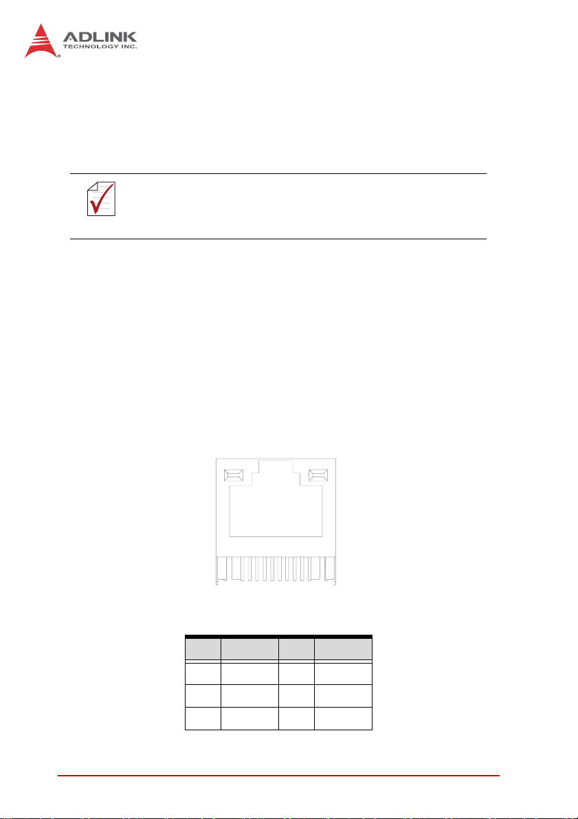
Both Gigabit Ethernet ports provide function indication through
LED display, as follows, with a yellow Activity indicator LED on the
right side of the port, and a green/orange Speed indicator LED on
the left. LED function is the same for both ports
Introduction 9
Page 22
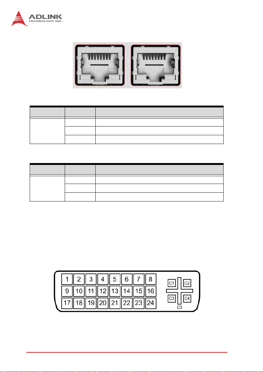
Figure 1-7: Gigabit Ethernet Ports
LED Color Status Description
OFF Ethernet port is disconnected.
Yell ow
LED Color Status Description
Green/Oran
ge
ON Ethernet port is connected with no activity.
Flashing Ethernet port is connected and active.
Table 1-5: Active/Link LED
OFF 10 Mbps
Green 100 Mbps
Orange 1000 Mbps
T able 1-6: Speed LED
1.6.6 DVI-I connector
The EOS-1200 provides one DVI-I connector for connection to an
external monitor. The DVI-I connector can be separated into VGA
and DVI-D (single link) interfaces.
Figure 1-8: DVI-I connector
10 Introduction
Page 23

EOS-1200
PIN Signal PIN Signal PIN Signal PIN Signal
1 DVIdata 2- 9 DVIdata 1- 17 DVIdata 0- C1
2 DVIdata 2+ 10 DVIdata 1+ 18 DVIdata 0+ C2
3 GND 11 GND 19 GND C3
4 CRT DDC clock 12 N/C 20 N/C C4
5 CRT DDC data 13 N/C 21 N/C C5
6 DVIDC clock 14 +5V 22 GND
7 DVIDC data 15 GND 23 DVI clock +
8
Analog vert.
sync
Table 1-7: DVI-I Connector Signals
16
Hot plug
detect
24 DVI clock -
Analog
Red
Analog
Green
Analog
Blue
Analog
horiz.
sync
Analog
GND
1.6.7 USB 2.0 Connectors
The EOS-1200 provides four Type A USB 2.0 ports on the front
panel. All are compatible with Hi-Speed, full-speed, and low-speed
USB devices.
The EOS-1200 supports multiple boot devices, including USB
flash, USB external HD, USB floppy, and USB CD-ROM drives.
Boot priority and device can be configured in BIOS. Please refer to
Section B.2.8 USB Configuration for details.
1.6.8 USB 3.0 Connectors
The EOS-1200 provides two Type A USB 3.0 ports on the front
panel. Based on the TI TUSB7320RKM USB host controller, connection to the host system is achieved through a PCIe x1 Gen2
Introduction 11
Page 24
interface, supporting SuperSpeed, Hi-Speed, full-speed, and
low-speed transmission for the downstream USB 3.0 ports.
The EOS-1200 supports multiple boot devices, including USB
flash, USB external HD, and USB CD-ROM drives. Boot priority
and device can be configured in BIOS.
While the USB 3.0 ports allow boot from CD-ROM, OS
installation via CD-ROM is not supported.
NOTE:
NOTE:
1.6.9 CFast Slot
The EOS-1200 is equipped with a type II push-push CFast host
connector on the front panel, connecting to the host controller by
SATA interface. Data transfer rates up to 3.0Gb/s(300MB/s)/
1.5Gb/s(150MB/s) are supported. The host SATA controller provides a legacy operating mode using I/O space, and an AHCI
operating mode using memory space. The CFast card can function as a storage device for system installation.
1.6.10 PoE (Power over Ethernet) Ports
LED2
LED1
8
Figure 1-9: PoE Port Connections
Pin Signal Pin Signal
1MDI0+5 MDI2-
2MDI0-6MDI1-
3MDI1+7MDI3+
12 Introduction
1
Page 25
EOS-1200
Pin Signal Pin Signal
4 MDI2+ 8 MDI3-
Table 1-8: PoE Port Connections Legend
Power over Ethernet support includes:
• Four fully-integrated Gigabit Ethernet Media Access Control (MAC)
and physical layer (PHY) ports
• Compliance with IEEE 802.3.af standard for a maximum of 8
W/channel with power up to 48 V over the existing CAT-5 W with
power up to 48 V over the e n
• Standard IEEE 802.3 Ethernet interface for 1000BASE-T,
100BASE-TX, and 10BASE-T applications (802.3, 802.3u, and
802.3ab)
• Smart PoE function provides manual power down of PoE supply
with software API
• 9 kB jumbo frame support
Four LEDs, numbered 0-4, are deployed on the front panel to indicate the status of each PoE port, lighting when the respective port
is active.
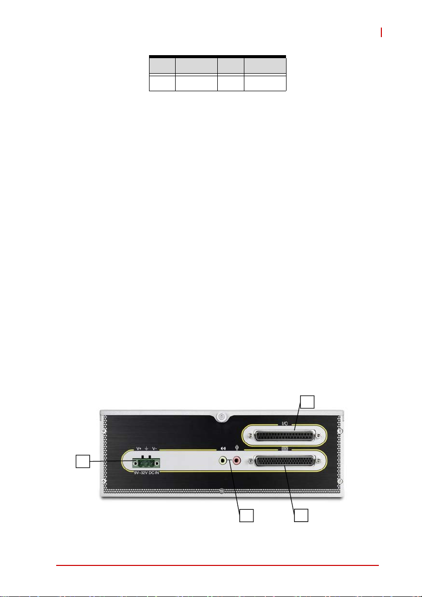
1.7 Rear Panel I/O Connectors
The EOS-1200 further provides I/O connection on the rear panel,
as follows.
N
K
L
Introduction 13
M
Page 26
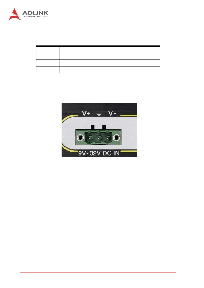
Figure 1-10: Rear Panel I/O Connectors
K DC Power Supply Connector
L Audio Jacks
M DB-62P COM Port Connector
N Digital I/O Connector
Table 1-9: Rear Panel I/O Connector Legend
1.7.1 DC Power Supply Connector
Figure 1-11: DC Power Connector
The DC power supply connector of the EOS-1200, on the back
panel, consists of V-, chassis ground, and V+ pins, from right to
left. V+ and V- pins accept DC power input and the chassis ground
pin grounds the chassis for better EMC compatibility. The DC
power input of the EOS-1200 allows a voltage input range from 9
VDC to 32 VDC.
1.7.2 Audio Jacks
The EOS-1200 implements Intel High Definition audio on a
Realtek ALC269 chip. The HD audio supports up to 24-bit, 192
KHz sample rate high quality headphone/speaker output and
microphone input, accessed on the back panel, pink for microphone input, and green for speaker output.
14 Introduction
Page 27

EOS-1200
1.7.3 DB-62P COM Port Connector
The EOS-1200 provides four COM ports with DB-62P Connector
on the back panel, with cable connect to DB-62P connector to
extend four D-SUB 9-pin connectors, at COM1, COM2,
COM3,and COM4. COM1 & COM2 can support RS-232/ RS-422/
RS-485 modes based on BIOS settings, and COM3 and COM4
ports support only RS-232. Pin assignments are as follows.
PIN Signal Name PIN Signal Name
1 COM3_TXD 22 COM3_RXD 43 COM3_CTS#
2 COM3_DTR# 23 COM3_DSR# 44 COM3_RTS#
3 COM3_RI# 24 COM3_DCD# 45 GND
4 COM4_TXD 25 COM4_RXD 46 COM4_CTS#
5 COM4_DTR# 26 COM4_DSR# 47 COM4_RTS#
6 COM4_RI# 27 COM4_DCD# 48 GND
7 COM1_TXD 28 COM1_RXD 49 COM1_CTS#
8 COM1_DTR# 29 COM1_DSR# 50 COM1_RTS#
9 COM1_RI# 30 COM1_DCD# 51 GND
10 COM2_TXD 31 COM2_RXD 52 COM2_CTS#
11 COM2_DTR# 32 COM2_DSR# 53 COM2_RTS#
12 COM2_RI# 33 COM2_DCD# 54 GND
13-21 N/C 34-42 N/C 55-62 N/C
Table 1-10: DB-62P Connector Pin Assignment
PIN
Signal Name
Introduction 15
Page 28

1.7.4 Rear Panel Digital I/O
The EOS-1200 features a 16-CH isolated digital I/O on its back
panel, based on an onboard digital I/O card supporting features as
follows.
16-CH Isolated DI 16-CH Isolated DO
Input Range : 0 – 24 V (please see
Section Reducing DI channel
Forward Current for High Voltage
Logic high: 5 – 24 V
Logic low: 0 – 2 V Isolated voltage: 2500 Vrms
Input resistance: 2.4 K
Allowed input current : 50mA per
channel (Max)
Isolation voltage: 2500 Vrms
Interrupt source: DI channel 0 to 15
Pin Definition Pin Definition
1DI020DI1
2DI221DI3
3DI422DI5
4DI623DI7
5DI824DI9
6 DI10 25 DI11
7 DI12 26 DI13
8 DI14 27 DI15
9 DI_COM1 28 DO_GND
10 DO_GND 29 DO_GND
11 DO0 30 DO 1
12 DO2 31 DO3
13 DO4 32 DO5
14 DO6 33 DO7
15 DO8 34 DO9
Output type: Darlington transistors
Sink current: Max 500 mA for each 8
channel set (DO 0~7 and DO 8~15)
16 Introduction
Page 29

Pin Definition Pin Definition
16 DO10 35 DO11
17 DO12 36 DO13
18 DO14 37 DO15
19 Clamp1
Table 1-11: Rear Panel Digital I/O Pin Definitions
Din Isolated digital input channel #n
Don Isolated digital output channel #n
Common Ground or Common power for
DI_COM1
DO_GND
Clamp1
Table 1-12: Rear Panel Digital I/O Pin Legend
front panel isolated input channels
(DI0~DI15)
Ground return path for isolated output
channels
Power input signal of clamp diode for
front panel DO channels (DO0~DO15)
EOS-1200
Introduction 17
Page 30
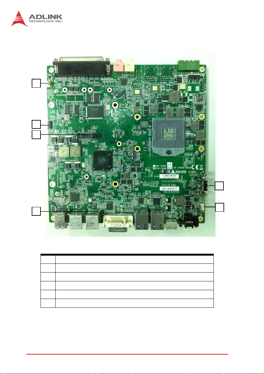
1.8 Internal I/O connectors
C
D
F
E
A
B
Figure 1-12: EOS-1200 Mainboard Top View
A Clear CMOS and ME RTC register jumpers
B DC 12 V fan connector
C DC 12 V fan connector (reserved)
D COM port connector (optional)
E USB 2.0 Type A connector
F SUMIT Connector
Table 1-13: Mainboard Connector Legend
18 Introduction
Page 31

EOS-1200
1.8.1 Clear CMOS and ME RTC Register Jumpers
When conditions occur under which the EOS-1200 controller fails
to boot, clearing stored BIOS content from CMOS and restoring
default settings may be required. To clear the CMOS, short pin#1
and pin#2 of JP1 and remove the jumper. CMOS restores to factory default settings
Normal Clear
As with JP1, shorting pin#1 and #2 of JP2 will clear the ME RTC
register, however, since this jumper is used by RMA, this is not
recommended, and may cause unexpected errors in system
behavior.
1.8.2 DC 12V Fan Connector
The EOS-1200 provides DC 12 V supply for fan module power.
The FAN module, inside the chassis, uses power directly from this
connector to exhaust heat, decreasing temperature of the system
for more stable operation.
1.8.3 DC 12V Fan Connector (reserved)
The EOS-1200 further reserves an additional DC 12 V supply connector for a second fan module. Like the first, the second module
is inside the chassis, and uses power directly from this connector
to exhaust heat, decreasing temperature of the system for more
stable operation.
1.8.4 USB 2.0 Type A Connector
A USB 2.0 Type A connector is provided to support expanded storage or security function through a dongle connection. The connector is deployed vertically, perpendicular to the board surface.
Introduction 19
Page 32

1.8.5 SUMIT Connector
SUMIT is a connection protocol that integrates common high-and
low-speed serial and legacy expansion buses for dedicated use. A
compact, stackable, multiboard I/O expansion solution, the SUMIT
connector supports one x1 PCI Express lane, one x4 PCI Express
lane, and additional power, ground and control signals. Pin defini-
tions are as follows.
Pin Description Pin Description
1 GND 27 PCIex4_TX2+
2 GND 28 PCIex4_RX2+
3 PCIex1_TX+ 29 PCIex4_TX2-
4 PCIex1_RX+ 30 PCIex4_RX2-
5 PCIex1_TX- 31 GND
6 PCIex1_RX- 32 GND
7 GND 33 PCIex4_TX3+
8 NC 34 PCIex4_RX3+
9 PCIex4_CLK+ 35 PCIex4_TX3-
10 PCIex1_CLK+ 36 PCIex4_RX3-
11 PCIex4_CLK- 37 GND
12 PCIex1_CLK- 38 GND
13 NC 39 PERST#
14 GND 40 WAKE#
15 PCIex4_TX0+ 41 +V12
16 PCIex4_RX0+ 42 +V12
17 PCIex4_TX0- 43 +V5
18 PCIex4_RX0- 44 +V12
19 GND 45 +V5
20 GND 46 +V3.3
21 PCIex4_TX1+ 47 +V5
22 PCIex4_RX1+ 48 +V3.3
23 PCIex4_TX1- 49 +V5
24 PCIex4_RX1- 50 +V3.3
25 GND 51 +V5
20 Introduction
Page 33

Pin Description Pin Description
26 GND 52 +V5SB
T a ble 1-14: SUMIT Pin Definitions
EOS-1200
SATA
Figure 1-13: EOS-1200 Mainboard Underside View
1.8.6 SATA Connectors
The EOS-1200 provides two SATA connectors supporting data
transfer up to 6.0 Gb/s(600 MB/s). The SATA host controller supports legacy mode using I/O space and AHCI mode using memory
space.
Introduction 21
Page 34

The SATA connectors are compatible with 2.5 inch hard disk
(HDD) or solid state disk (SSD) drives, which must be installed to
the SATA connector with a HDD bracket.
1.9 General Purpose Digital Signals
1.9.1 General Purpose Digital Output (EDO)
In the common ground connection of isolated digital output, as
shown, when a “1” (logic high) is written by FPGA to a DO channel, the sink current passes through the transistors and the DO
channel goes low. When a “0” (logic low) is written by FPGA to a
DO channel, no current passes through the transistors and the DO
channel goes high. When the load is of an “inductance nature”
such as a relay, coil or motor, the VDD pin must be connected to
an external power source. The extra connection is utilized for the
‘fly-wheel diode’ to form a current-release closed loop, so that the
transistors are protected from any high reverse voltage generated
by the inductance load when the output is switched from high to
low.
User Pull
User
Device
Load
High
Vdd
User DI
Do From
FPGA
EOS-1200
Iso_+5V
Clamp
DO
PC3H4
ISO_GND
User
Device
GND
22 Introduction
Page 35

EOS-1200
1.9.2 General Purpose Digital Input (EDI)
The EOS-1200 provides 16 opto-isolated digital input channels on
the front panel. Circuitry of the isolated input channel is as follows.
Ri
DIn
If
DICOM
Photo Coupler
As shown, signal connections for a supply and load connected to
an isolated input, here in the EOS-1200, can determine when a
load is powered. The load is connected to the power supply by a
switch and can be any DC voltage between 0 and 24 VDC. When
the switch is open, no current flows through the load and no voltage is applied to the load or to the EOS-1200 DI channels.
The digital logic of the EOS-1200 then registers a logic high for the
channel. When the switch is closed, current flows through the
diode and the EOS-1200 registers logic low for the channel.
Introduction 23
Page 36

10 k
+3.3V
EOS-1200
Digital Logic
Computer
Ground
2.4 k
DI
Load
ISO_COM
Reducing DI channel Forward Current for High Voltage
As input voltage increases above 5 V, the input current drawn
by the EOS-1200 (forward current If) rises commensurately. At
24 V, for example, current per line is determined by the formula:
(24V- 0.5V)/2.4Kohm = 9.79 mA
Supply
Isolated
Ground
24 Introduction
Page 37

EOS-1200
To reduce the current and the power drawn, on a monitored circuit, for example, another resistor can be added in series with
the 2.4 kΩ current-limiting resistor, as shown.
10 k
+3.3
V
Computer
Ground
EOS-1200
2.4 k
If
ISO_COM
Rs
DI
L
o
a
d
Supply
It is recommended a resistance value be chosen allowing at least
5 mA through the diode, assuming a maximum drop across the
diode of 0.5 V.
For example, for 24 V inputs a maximum resistance for Rs can be
found by the formula:
(24 V-0.5 V)/5 mA – 2.4 kΩ = 2.3 kΩ
Introduction 25
Page 38

This page intentionally left blank.
26 Introduction
Page 39

2 Getting Started
This chapter describes accessing/changing memory modules,
hard disk drives, and the USB dongle in the system. Wallmounting is also described.
2.1 Installing Memory
1. Remove the two screws securing the bottom cover and
remove, as shown.
EOS-1200
2. Insert the memory module into the DDR3 SO-DIMM
socket at a 45° angle and press down until the module is
properly seated.
Getting Started 27
Page 40

2.2 Installing a Hard Disk Drive (HDD)
1. Remove the two screws securing the bottom cover and
remove, as shown.
2. Remove the two screws fixing the hard drive carriage.
3. Slide the hard drive carriage out.
4. Remove the four screws from the hard drive to be
removed.
5. Secure the new hard drive to the hard drive carriage.
6. Slide the hard drive carriage in, until received securely in
the SATA power and data connectors.
7. Secure the hard drive carriage.
8. Replace the bottom cover.
28 Getting Started
Page 41
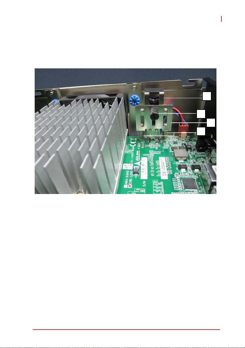
2.3 Installing the USB Dongle
1. Remove the top cover by loosening the thumbscrew by
hand or a screwdriver.
EOS-1200
C
B
D
A
2. Once the USB dongle mounting bracket base D is fixed
to the board surface via standoffs A, unscrew the thumbscrew B and loosen the USB dongle retainer C.
3. Slide the USB dongle retainer C upward to accommo-
date the USB dongle.
4. Plug the USB dongle into the USB port.
5. Slide the USB dongle retainer C down to secure USB
dongle D to USB dongle mounting bracket base A and
fasten thumbscrew B.
Getting Started 29
Page 42

2.4 Installing Wall-Mount Brackets
1. Secure the wall-mount brackets in the four screwholes
provided on the underside of the chassis, as shown
2.5 Operating System Installation
The EOS-1200 is compatible with several operating systems for
maximum flexibility. Installation instructions for each follow. For
other OS support, please contact ADLINK for further information.
30 Getting Started
Page 43

2.5.1 Windows XP
Installing AHCI on Windows XP
Windows XP can be installed on an AHCI-enabled system by
BIOS settings.
Press “Delete” to enter the BIOS, and go to “SATA Configuration→SATA mode” to select AHCI.
Install the Intel(R) Mobile Express Chipset SATA AHCI Controller driver over USB after pressing F6. If the driver is already
running in IDE (ATA) emulation mode, no installation is
required.
Windows XP
Windows XP supports EOS-1200 chipset drivers, allowing simple installation. ADLINK also provides pre-installation services
for Windows XP on the EOS-1200 (when the Windows XP
license is pre-purchased from ADLINK).
Windows XP Embedded
As a result of its overwhelming popularity, human-machine
interface, and plentiful development tools, Windows XP is well
suited to comparatively simple application development.
Embedded XP is simply a modularized Windows XP. System
developers select only the needed Windows XP components
and functions and then organize them to construct an XP
Embedded OS.
EOS-1200
With this architectural modularization, system integrators can
readily reduce storage space requirements of XP Embedded.
The only factor determining storage space requirements is the
number of function modules needed.
Because XP Embedded is wholly compatible with Windows XP,
developers can compile controller software in the Windows XP
environment and transfer the code to Embedded XP for immediate use. No new tools are required to use XP Embedded,
lowering software development costs. Another advantage is
the cost of licensing Embedded XP being much less than that
of Windows XP.
Getting Started 31
Page 44

ADLINK currently provides standard XP Embedded OS images
for the EOS-1200 (XP Embedded license pre-purchase from
ADLINK is required). The standard XP Embedded OS image
provided by ADLINK is about 1.4 GB, and key features include:
ZXP Embedded OS Kernel
ZDrivers for EOS H/W and peripheral cards
ZTCP/IP Networking
ZTCP/IP with file sharing and client for Microsoft net-
work
ZInternet Explorer
ZFile Manager
ZLanguage Support
The standard XP Embedded OS image meets most application
needs. If you have any special functional requirements for XP
Embedded, please contact ADLINK for more details.
32 Getting Started
Page 45

2.5.2 Windows 7
Installing AHCI on Windows 7
The AHCI driver must be enabled in the registry before SATA
mode of the boot drive can be changed, as follows:
1. Exit all Windows-based programs
2. In the Start menu, enter regedit in the Start Search box,
and select ENTER
3. If the User Account Control dialog box appears, select
Continue
4. Locate and select the registry subkey
HKEY_LOCAL_MACHINESystemCurrentControlSetS
ervicesMsahci
5. In the Name column of the right pane, right-click Start,
and select Modify
6. In the Value data box, enter 0 and select OK
7. In the File menu, select Exit to close the Registry Editor
8. Restart the computer, open the BIOS and enable AHCI.
At the next Windows login, the drivers for AHCI show as
intalled.
9. Restart a final time to complete the installation
EOS-1200
Windows 7
Windows 7 supports EOS-1200 chipset drivers, allowing simple
installation. ADLINK also provides pre-installation services for
Windows 7 on the EOS-1200 (when the Windows XP license is
pre-purchased from ADLINK). For more information, please visit
the OS website
Windows 7 Embedded Service Pack 1
Windows Embedded Standard 7 SP1 delivers the power, familiarity, and reliability of the Windows 7 operating system in a
componentized form, allowing developers to create advanced
Getting Started 33
Page 46

commercial and consumer devices compatible with thousands
of existing Windows applications and drivers.
You can download the evaluation version from: http://
www.microsoft.com/download/en/details.aspx?id=11887
The download contains 3 DVD5 images (ISO's). Download the
.exe and .rar files for each DVD image into its own folder and
run the .exe file in that folder to reconstitute the .ISO file. Once
the .ISO file is created you can then burn the ISO onto a blank
DVD. The toolkit DVD is used to install the Image Configuration
Editor (ICE) and associated distribution share(s) onto a PC.
The 32-bit and 64-bit Standard 7 SP1 DVDs are bootable
WinPE DVDs that contain the Image Builder Wizard (IBW) and
the corresponding 32-bit or 64-bit distribution share. Typically
these DVDs are used to boot into Windows PE on the target
device and apply the runtime image created with ICE or to prototype image creation using the wizard and various templates
available in IBW.
Please read the Windows Embedded Standard 7 SP1 documentation for more information on using ICE and IBW to create
and deploy runtime images.
34 Getting Started
Page 47

EOS-1200
2.6 Driver Installation
After the OS is installed, all related drivers must be installed. This
section describes drivers needed for Windows operating systems
and installation procedures. For other OS support, please contact
ADLINK directly.
Once Windows is properly installed, the following installations are
required (most standard I/O device drivers have been included in
the Windows install):
1. Install the chipset driver
2. Install the graphics driver
3. Install the Ethernet driver
4. Install the audio driver
5. Install the USB3.0 driver
6. Install the ME (Management Engine Components) soft-
ware
7. Install the Digital Input/ Output Driver
2.6.1 Chipset Driver Installation
The chipset driver directs the operating system to configure the
®
Intel
QM67 chipset, to ensure that the following features function
properly:
Z Core PCI and ISAPNP services
Z PCIe support
Z SATA storage support
Z USB support
Z Identification of Intel® Chipset components in the Device
Manager
To install the chipset driver:
1. Close any running applications
2. Execute Chipset.exe and follow onscreen instructions
3. Reboot the system
Getting Started 35
Page 48

2.6.2 Graphics Driver Installation
The EOS-1200 is equipped with the Intel® HD graphics family. To
install the graphics driver:
1. Close any running applications
2. Execute Setup.exe in the Graphics folder and follow the
onscreen instructions
3. Reboot the system
2.6.3 Ethernet Driver Installation
To install the driver for the Intel® 82574L/82579LM Gigabit network connection:
1. Close any running applications
2. Execute Network.exe and follow onscreen instructions
3. Reboot the system
2.6.4 Audio Driver Installation
Please follow the following steps to install the Realtek audio driver:
1. Close any running applications
2. Execute Setup.exe in Audio folder and follow the
onscreen instructions
3. Reboot the system
2.6.5 USB 3.0 Driver Installation
Please follow the following steps to install the Texas Instruments
USB 3.0 driver:
1. Close any running applications
2. Execute Texas Instruments xHCI Driver v1.12.7 ( WHQL
- Multilanguage ).exe in the USB3 folder and follow the
onscreen instructions to complete the setup
3. Reboot the system
36 Getting Started
Page 49

EOS-1200
2.6.6 ME (Management Engine Components) Software
Installation
The Intel® Management Engine software components requiring
installation depend on the system's specific hardware and firmware features.
The installer detects system capabilities and installs the relevant
drivers and applications.
To install the ME Software:
1. Close any running applications
2. Execute Setup.exe in the ME_SW folder and follow the
onscreen instructions
2.6.7 Digital Input/ Output Driver Installation
To install the driver for ADLINK DIO:
1. Close any running applications.
2. Execute PCMe-1432_x86/64_v0.0.0.7.exe and follow
the onscreen instructions to complete the setup.
3. Reboot the system.
Getting Started 37
Page 50

Following successful installation, the PCMe-1432 should appear in
the directory, as shown.
38 Getting Started
Page 51

Appendix A Function Library
This chapter provides a detailed description of the EOS-1200
function library. These functions, excluding SmartPoE and
EEPROM, are compatible with the PCIS-DASK library, and can be
used to develop applications under C++, C#, VB.Net, and Delphi.
A.1 List of Functions
Category Function
Register_Card
Release_Card
System & Initialization
DI/O
COS Interrupt
Smart PoE SmartPoE_SetPower
EEPROM
GetBaseAddr
GetCardIndexFromID
GetCardType
GetLCRAddr
DI_ReadLine
DI_ReadPort
DO_ReadLine
DO_WriteLine
DO_ReadPort
DO_WritePort
DIO_INT_Event_Message
DIO_INT1_EventMessage
DIO_INT2_EventMessage
DIO_SetDualInterrupt
DIO_SetCOSInterrupt32
DIO_GetCOSLatchData32
EEPROM_ReadByte
EEPROM_WriteByte
EEPROM_WriteBytes
EOS-1200
Function Library 39
Page 52

A.2 Data Types.
Type Description Range
U8 8-bit ASCII character 0 to 255
I16 16-bit signed integer -32768 to 32767
U16
I32 32-bit signed integer
U32
F32
F64
16-bit unsigned
integer
32-bit unsigned
integer
32-bit single-
precision floating-
point
64-bit double-
precision floating-
point
0 to 65535
-2147483648 to
2147483647
0 to 4294967295
-3.402823E38 to
3.402823E38
-1.797683134862315E308
to
1.797683134862315E308
A.3 Setting Up the Build Environment
A.1.1 Include Files
All applications using API are required to include the following
files.
Include File Description
Dask.h Header file required for all C/C++
applications.
Dask.vb Function definitions required for all VB.Net
applications.
Dask.cs Function definitions required for all C#
applications.
PCMe1432.h Header file required for all C/C++
applications.
PCMe1432.vb Function definitions required for all VB.Net
applications.
PCMe1432.cs Function definitions required for all C#
applications.
40 Function Library
Page 53

EOS-1200
A.1.2 Library Files
All C/C++ applications using API require the following library files.
Library File Description
PCI-Dask.lib Exports API function definitions;
required for all Visual C/C++ 32 bit
applications.
PCI-DASK_bcb.lib Exports API function definitions;
required for all 32 bit Borland C++
Builder applications.
PCMe1432.lib Exports API function definitions;
required for all Visual C/C++ 32 bit
applications.
PCI-Dask64.lib Exports API function definitions;
required for all Visual C/C++ 64 bit
applications.
PCMe1432x64.lib Exports API function definitions;
required for all Visual C/C++ 64 bit
applications.
A.1.3 DLL Files
All applications using API require the following DLL files.
All files are located in [Installed directory]\ADLINK\PCMe1432\Include, where ‘Installed directory’ is the destination directory specified in the setup program.
DLL File Description
PCI-Dask.dll Dynamic link library. Required for all
applications.
PCMe1432.dll Dynamic link library. Required for all
applications.
Function Library 41
Page 54

A.2 System & Initialization Functions
A.1.1 Register_Card
Description
Initializes the hardware and software states of a NuDAQ
PCI-bus data acquisition card, and returns a numeric card
ID corresponding to the initialized card. Register_Card must
be called before any other PCIS-DASK library functions can
be called for a particular card. The function initializes the
card and variables internal to the PCIS-DASK library.
Because NuDAQ PCI-bus data acquisition cards meet plugand-play specifications, the base address (pass-through
address) and IRQ level are assigned directly by the system
BIOS.
Syntax
C/C++
I16 Register_Card (U16 CardType, U16 card_num)
Visual Basic
Register_Card (ByVal CardType As Integer,
ByVal card_num As Integer) As Integer
VB.Net
Register_Card (ByVal CardType As Short, ByVal
card_num As Short) As Short
C#
short Register_Card (ushort CardType, ushort
card_num)
Parameter(s)
CardType
Type of card to be initialized. ADLINK periodically upgrades
PCIS-DASK to add support for new NuDAQ PCI-bus data
acquisition cards and NuIPC CompactPCI cards. Refer to
release notes of the card to dtermine whether PCIS-DASK
42 Function Library
Page 55

EOS-1200
supports that card. These are the constants defined in
DASK.H that represent the NuDAQ PCI-bus data acquisition cards supported by PCIS-DASK:
PCMe_1432
card_num
Sequence number of the card with the same card type (as
defined in argument CardType) or that belongs to the same
card type series (except PCI- 7300A_Rev. A and PCI7300A Rev. B) in the PCI slot. card_num is always equal to
0 for PCMe-1432.
Return Code
Returns a numeric card ID for the initialized card. The card ID
range is between 0 and 31. If any error occurs, a negative error
code is returned, with possible error codes as follows:
ErrorTooManyCardRegistered
ErrorUnknownCardType
ErrorOpenDriverFailed
ErrorOpenEventFailed
A.1.2 Release_Card
Description
A maximum of 32 cards can be registered simultaneously.
This function informs the PCIS-DASK library that the registered card is not currently in use and can be released.
Releasing a card clears space for a new card to register.
This function is also applied at the end of a program to
release all registered cards.
Syntax
C/C++
I16 Release_Card (U16 CardNumber)
Visual Basic
Release_Card (ByVal CardNumber As Integer) As
Integer
Function Library 43
Page 56

VB.Net
Release_Card (ByVal CardNumber As Short) As
Short
C#
short Release_Card (ushort CardNumber)
Parameter(s)
CardNumber
ID of the card for release.
Return Code(s)
NoError
A.1.3 GetBaseAddr
Description
Acquires I/O base addresses of the device with a specified
card index
Syntax
C/C++
I16 GetBaseAddr (U16 CardNumber, U32 *BaseAddr, U32 *BaseAddr2)
Visual Basic
GetBaseAddr (ByVal CardNumber As Integer,
BaseAddr As Long, BaseAddr2 As Long) As Integer
VB.Net
Release_Card (ByVal CardNumber As Short) As
Short
C#
short GetBaseAddr (ushort CardNumber, uint []
BaseAddr, uint [] BaseAddr2)
44 Function Library
Page 57

Parameter(s)
CardNumber
ID of the card for release.
BaseAddr
Returns the I/O base address.
BaseAddr2
Returns the second base address #2. This is only available
in cards that support two I/O base addresses, such as PCI9113 and PCI-9114. For PCI-6202, PCI-9221, PCI-9222,
and PCI-9223, this parameter returns the memory address
of the specified card.
Return Code(s)
NoError
ErrorInvalidCardNumber
ErrorCardNotRegistered
ErrorFuncNotSupport
A.1.4 GetCardIndexFromID
EOS-1200
Description
Obtains the card type and the sequence number of the
device with a specified card ID. This is the reverse function
of Release_Card.
Syntax
C/C++
I16 GetCardIndexFromID (U16 CardNumber, U16
*cardType, U16 *cardIndex)
Visual Basic
GetCardIndexFromID (ByVal CardNumber As Integer, cardType As Integer, cardIndex As Integer) As Integer
Function Library 45
Page 58

VB.Net
GetCardIndexFromID (ByVal CardNumber As Short,
ByRef cardType As Short, ByRef cardIndex As
Short) As Short
C#
short GetCardIndexFromID (ushort CardNumber,
out ushort cardType, out ushort cardIndex)
Parameter(s)
CardNumber
ID of the card for release.
CardType
Returns the card type.
CardIndex
Returns the sequence number of the card of the same type
Return Code(s)
NoError
ErrorInvalidCardNumber
ErrorCardNotRegistered
ErrorFuncNotSupport
A.1.5 GetCardType
Description
Obtains the card type of the device with a specified card
index.
Syntax
C/C++
I16 GetCardType (U16 CardNumber, U16 *cardType)
Visual Basic
GetCardType (ByVal CardNumber As Integer,
cardType As Integer) As Integer
46 Function Library
Page 59

VB.Net
GetCardType (ByVal CardNumber As Short, ByRef
cardType As Short) As Short
C#
short GetCardType (ushort CardNumber, out ushort cardType)
Parameter(s)
CardNumber
ID of the card for release.
CardType
Returns the card type.
Return Code(s)
NoError
ErrorInvalidCardNumber
ErrorCardNotRegistered
ErrorFuncNotSupport
A.1.6 GetLCRAddr
EOS-1200
Description
Obtains the LCR base address of the device with a specified card index as defined by the onboard PCI controller.
Syntax
C/C++
I16 GetLCRAddr(U16 CardNumber, U32 *LcrAddr)
Visual Basic
GetLCRAddr (ByVal CardNumber As Integer,
LcrAddr As Long) As Integer
VB.Net
GetLCRAddr (ByVal CardNumber As Short, ByRef
LcrAddr As Integer) As Short
Function Library 47
Page 60

C#
short GetLCRAddr(ushort CardNumber, uint []
LcrAddr)
Parameter(s)
CardNumber
ID of the card for release.
LcrAddr
Returns the LCR base address.
Return Code(s)
NoError
ErrorInvalidCardNumber
ErrorCardNotRegistered
ErrorFuncNotSupport
A.2 DI/O Functions
A.1.1 DI_ReadLine
Description
Reads the digital logic state of the digital line in the specified
port.
Syntax
C/C++
I16 DI_ReadLine (U16 CardNumber, U16 Port, U16
Line, U16 *State)
Visual Basic
DI_ReadLine (ByVal CardNumber As Integer,
ByVal Port As Integer, ByVal Line As Integer,
State As Integer) As Integer
VB.Net
48 Function Library
Page 61

DI_ReadLine (ByVal CardNumber As Short, ByVal
Port As Short, ByVal Line As Short, ByRef State
As Short) As Short
C#
short DI_ReadLine (ushort CardNumber, ushort
Port, ushort Line, out ushort State)
Parameter(s)
CardNumber
ID of the card for release.
Port
Digital input port number. Valid values: PCMe-1432 0, 1
Line
Digital line to be read. Valid values:PCMe-1432 0 to 15 (for
port 0 and port 1)
State
Returns the digital logic state of the specified line to 0 or 1
Return Code(s)
NoError
ErrorInvalidCardNumber
ErrorCardNotRegistered
ErrorFuncNotSupport
ErrorInvalidIoChannel
EOS-1200
A.1.2 DI_ReadPort
Description
Reads the digital data from the specified digital input port.
Syntax
C/C++
I16 DI_ReadPort (U16 CardNumber, U16 Port, U32
*Value)
Function Library 49
Page 62

Visual Basic
DI_ReadPort (ByVal CardNumber As Integer,
ByVal Port As Integer, Value As Long) As Integer
VB.Net
DI_ReadPort (ByVal CardNumber As Short, ByVal
Port As Short, ByRef Value As Integer) As Short
C#
short DI_ReadPort (ushort CardNumber, ushort
Port, out uint Value)
Parameter(s)
CardNumber
ID of the card for release.
Port
Digital input port number. Valid values: PCMe-1432 0, 1
Value
Returns the digital data read from the specified port. Valid
values: PCMe-1432 16-bit data (for port 0 and port 1)
Return Code(s)
NoError
CardNotRegistered
ErrorInvalidCardNumber
ErrorCardNotRegistered
ErrorFuncNotSupport
A.1.3 DO_ReadLine
Description
Reads back the digital logic state of the specified digital output line of the specified port.
Syntax
C/C++
50 Function Library
Page 63

I16 DO_ReadLine (U16 CardNumber, U16 Port, U16
Line, U16 *State)
Visual Basic
DO_ReadLine (ByVal CardNumber As Integer,
ByVal Port As Integer, ByVal Line As Integer,
State As Integer) As Integer
VB.Net
DO_ReadLine (ByVal CardNumber As Short, ByVal
Port As Short, ByVal Line As Short, ByRef State
As Short) As Short
C#
short DO_ReadLine (ushort CardNumber, U16 ushort, ushort Line, out ushort State)
Parameter(s)
CardNumber
ID of the card for release.
Port
Digital input port number. Valid values: PCMe-1432 0, 1
Line
Digital line to be read. Valid values: PCMe-1432 0 to 15 (for
port 0 and port 1)
EOS-1200
State
Returns the digital logic state, 0 or 1, of the specified line.
Return Code(s)
NoError
ErrorInvalidCardNumber
ErrorCardNotRegistered
ErrorFuncNotSupport
ErrorInvalidIoChannel
Function Library 51
Page 64

A.1.4 DO_WriteLine
Description
Sets the specified digital output line in the specified digital
port to the specified state. This function is only available for
cards that support digital output readback.
Syntax
C/C++
I16 DO_WriteLine (U16 CardNumber, U16 Port,
U16 Line, U16 State)
Visual Basic
DO_WriteLine (ByVal CardNumber As Integer,
ByVal Port As Integer, ByVal Line As Integer,
State As Integer) As Integer
VB.Net
DO_WriteLine (ByVal CardNumber As Short, ByVal
Port As Short, ByVal Line As Short, ByRef State
As Short) As Short
C#
short DO_WriteLine (ushort CardNumber, U16
ushort, ushort Line, out ushort State)
Parameter(s)
CardNumber
ID of the card for release.
Port
Digital input port number. Valid values: PCMe-1432 0, 1
Line
Digital line to be read. Valid values: PCMe-1432 0 to 15 (for
port 0 and port 1)
State
Returns the digital logic state, 0 or 1, of the specified line.
52 Function Library
Page 65

Return Code(s)
NoError
ErrorInvalidCardNumber
ErrorCardNotRegistered
ErrorFuncNotSupport
ErrorInvalidIoChannel
A.1.5 DO_ReadPort
Description
Reads back the output digital data from the specified digital
output port.
Syntax
C/C++
I16 DO_ReadPort (U16 CardNumber, U16 Port, U32
*Value)
Visual Basic
DO_ReadPort (ByVal CardNumber As Integer,
ByVal Port As Integer, Value As Long) As Integer
VB.Net
DO_ReadPort (ByVal CardNumber As Short, ByVal
Port As Short, ByRef Value As Integer) As Short
C#
short DO_ReadPort (ushort CardNumber, ushort
Port, out uint Value)
EOS-1200
Parameter(s)
CardNumber
ID of the card for release.
Port
Digital input port number. Valid values: PCMe-1432 0, 1
Value
Function Library 53
Page 66

Returns the digital data read from the specified output port.
Valid values: PCMe-1432 16-bit data (for port 0 and port 1)
Return Code(s)
NoError
ErrorInvalidCardNumber
ErrorCardNotRegistered
ErrorFuncNotSupport
ErrorInvalidIoChannel
A.1.6 DO_WritePort
Description
Writes digital data to the specified digital output port.
Syntax
C/C++
I16 DO_WritePort (U16 CardNumber, U16 Port,
U32 Value)
Visual Basic
DO_WritePort (ByVal CardNumber As Integer,
ByVal Port As Integer, ByVal Value As Long) As
Integer
VB.Net
DO_WritePort (ByVal CardNumber As Short, ByVal
Port As Short, ByVal Value As Integer) As Short
C#
short DO_WritePort (ushort CardNumber, ushort
Port, uint Value)
Parameter(s)
CardNumber
ID of the card for release.
Port
Digital input port number. Valid values: PCMe-1432 0, 1
54 Function Library
Page 67

Value
Returns the digital data read from the specified output port.
Valid values: PCMe-1432 16-bit data (for port 0 and port 1)
Return Code(s)
NoError
ErrorInvalidCardNumber
ErrorCardNotRegistered
ErrorFuncNotSupport
ErrorInvalidIoChannel
A.2 COS Interrupt Functions
A.1.1 DIO_INT_Event_Message
Description
Controls and notifies the user application when a specified
interrupt event occurs. The notification is executed through
a user-specified callback function or the Windows PostMessage API. When a new event message is added, it remains
active until the function is called by setting the argument
mode to 0, removing the specified interrupt event message.
To remove a specified message, make sure to specify the
event handle to be notified for the message.
EOS-1200
Syntax
C/C++
I16 DIO_INT_EventMessage (U16 CardNumber, I16
mode, HANDLE evt, HANDLE windowHandle, U32
message, U32 callbackAddr)
Visual Basic
DIO_INT_EventMessage (ByVal CardNumber As
Integer, ByVal mode As Integer, ByVal evt As
Long, ByVal windowHandle As Long, ByVal message As Long, ByVal callbackAddr As Long) As
Integer
VB.Net
Function Library 55
Page 68

DIO_INT_EventMessage (ByVal CardNumber As
Short, ByVal mode As Short, ByVal evt As Integer, ByVal windowHandle As Integer, ByVal message As Integer, ByVal callbackAddr As
CallbackDelegate) As Short
C#
short DIO_INT_EventMessage (ushort CardNumber,
short mode, long evt, long windowHandle, uint
message, MulticastDelegate callbackAddr)
Parameter(s)
CardNumber
ID of the card for release.
Mode
Operating mode for adding or removing messages, wherein
0: Remove an existing message interrupt event defined
argument evt.
1: Add a new message for an interrupt event defined
evt
Handle of the INT event to handle
windowHandle
Handle to the window in which a Windows message will be
received when the specified INT event occurs; if windoHandle is 0, no Windows messages will be sent
Message
User-defined message issued when the specified INT event
occurs. The message can be of any value. In Windows, the
message can be set to a value including any Windows predefined messages, such as WM_PAINT. To define a custom
message, any value ranging from WM_USER (0x400) to
0x7fff can be used, this range reserved by Windows for
same.
callbackAddr
56 Function Library
Page 69

Address of the user callback function. The PCIS-DASK calls
this function when the specified INT event occurs. If no callback function is required, set callbackAddr to 0.
Return Code(s)
NoError
ErrorInvalidCardNumber
ErrorCardNotRegistered
ErrorFuncNotSupport
A.1.2 DIO_INT1_EventMessage
Description
Controls the INT1 interrupt sources for a dual-interrupt system and notifies the user's application when an interrupt
event occurs. The notification is performed through a userspecified callback function or the Windows PostMessage
API.
Syntax
C/C++
I16 DIO_INT1_EventMessage (U16 CardNumber, I16
Int1Mode, HANDLE windowHandle, U32 message,
void *callbackAddr())
Visual Basic
DIO_INT1_EventMessage (ByVal CardNumber As
Integer, ByVal Int1Mode As Integer, ByVal windowHandle As Long, ByVal message As Long,
ByVal callbackAddr As Long) As Integer
VB.Net
DIO_INT1_EventMessage (ByVal CardNumber As
Short, ByVal Int1Mode As Short, ByVal windowHandle As Integer, ByVal message As Integer,
ByVal callbackAddr As CallbackDelegate) As
Short
C#
EOS-1200
Function Library 57
Page 70

short DIO_INT1_EventMessage (ushort CardNumber, short Int1Mode, long windowHandle, long
message, MulticastDelegate callbackAddr)
Parameter(s)
CardNumber
ID of the card performing the operation
Int1Mode
Interrupt mode of INT1. Valid values:
INT1_DISABLE
INT1_EXT_SIGNALINT1 by COS of Ch0 of Port 0
windowHandle
Handle to the window in which a Windows message will be
received when the specified INT event occurs; if windoHandle is 0, no Windows messages will be sent
Message
User-defined message issued when the specified INT event
occurs. The message can be of any value. In Windows, the
message can be set to a value including any Windows predefined messages, such as WM_PAINT. To define a custom
message, any value ranging from WM_USER (0x400) to
0x7fff can be used, this range reserved by Windows for
same.
callbackAddr
Address of the user callback function. The PCIS-DASK calls
this function when the specified INT event occurs. If no callback function is required, set callbackAddr to 0.
Return Code(s)
NoError
ErrorInvalidCardNumber
ErrorCardNotRegistered
ErrorFuncNotSupport
58 Function Library
Page 71

A.1.3 DIO_INT2_EventMessage
Description
Controls the INT2 interrupt sources for a dual-interrupt system and notifies the active application when an interrupt
event occurs. The notification is executed via a user-specified callback function or the Windows PostMessage API.
Syntax
C/C++
I16 DIO_INT2_EventMessage (U16 CardNumber, I16
Int2Mode, HANDLE windowHandle, U32 message,
void *callbackAddr())
Visual Basic
DIO_INT2_EventMessage (ByVal CardNumber As
Integer, ByVal Int2Mode As Integer, ByVal windowHandle As Long, ByVal message As Long,
ByVal callbackAddr As Long) As Integer
VB.Net
DIO_INT2_EventMessage (ByVal CardNumber As
Short, ByVal Int1Mode As Short, ByVal windowHandle As Integer, ByVal message As Integer,
ByVal callbackAddr As CallbackDelegate) As
Short
C#
short DIO_INT2_EventMessage (ushort CardNumber, short Int1Mode, long windowHandle, long
message, MulticastDelegate callbackAddr)
EOS-1200
Parameter(s)
CardNumber
ID of the card performing the operation
Int2Mode
Function Library 59
Page 72

INT2 interrupt mode. Valid values:
ZINT2_DISABLE
ZINT2_EXT_SIGNAL INT2 by COS of Ch1 of Port 0
windowHandle
Handle to the window in which a Windows message will be
received when the specified INT event occurs; if windoHandle is 0, no Windows messages will be sent
Message
User-defined message issued when the specified INT event
occurs. The message can be of any value. In Windows, the
message can be set to a value including any Windows predefined messages, such as WM_PAINT. To define a custom
message, any value ranging from WM_USER (0x400) to
0x7fff can be used, this range reserved by Windows for
same.
callbackAddr
Address of the user callback function. The PCIS-DASK calls
this function when the specified INT event occurs. If no callback function is required, set callbackAddr to 0.
Return Code(s)
NoError
ErrorInvalidCardNumber
ErrorCardNotRegistered
ErrorFuncNotSupport
A.1.4 DIO_SetDualInterrupt
Description
Informs the PCIS-DASK library of the interrupt mode of two
interrupt sources of a dual-interrupt system and returns dual
interrupt events. If an interrupt is generated, the corresponding interrupt events are signaled. The application
uses Win32 wait functions, such as WaitForSingleObject or
WaitForMultipleObjects to check the interrupt event status.
60 Function Library
Page 73

Syntax
C/C++
I16 DIO_SetDualInterrupt (U16 CardNumber, I16
Int1Mode, I16 Int2Mode, HANDLE *hEvent)
Visual Basic
DIO_SetDualInterrupt (ByVal CardNumber As
Integer, ByVal Int1Mode As Integer, ByVal
Int2Mode As Integer, hEvent As Long) As Integer
VB.Net
DIO_SetDualInterrupt (ByVal CardNumber As
Short, ByVal Int1Mode As Short, ByVal Int2Mode
As Short, ByRef hEvent() As IntPtr) As Short
C#
short DIO_SetDualInterrupt (ushort CardNumber,
short Int1Mode, short Int2Mode, ref IntPtr[]
hEvent)
Parameter(s)
CardNumber
ID of the card performing the operation
EOS-1200
Int1Mode
The interrupt mode of INT1. Valid values:
ZINT1_DISABLE
ZINT1_EXT_SIGNALINT1 by COS of Ch0 of Port 0
Int2Mode
INT2 interrupt mode. Valid values:
ZINT2_DISABLE
ZINT2_EXT_SIGNAL INT2 by COS of Ch1 of Port 0
hEvent
Returned dual-interrupt event handles. The status of a dualinterrupt event indicates that an interrupt is generated or not
for cards comprising dual-interrupt system.
Function Library 61
Page 74

Return Code(s)
NoError
ErrorInvalidCardNumber
ErrorCardNotRegistered
ErrorFuncNotSupport
A.1.5 DIO_SetCOSInterrupt32
Description
Enables or disables the COS (Change Of State) interrupt
detection capability of the specified ports with 32-bit data
width.
Syntax
C/C++
I16 DIO_SetCOSInterrupt32 (U16 CardNumber, U8
Port, U32 ctl, HANDLE *hEvent, BOOLEAN ManualReset)
Visual Basic
DIO_SetCOSInterrupt32 (ByVal CardNumber As
Integer, ByVal Port As Byte, ByVal ctl As Long,
hEvent As Long, ByVal ManualReset As Byte) As
Integer
VB.Net
DIO_SetCOSInterrupt32 (ByVal CardNumber As
Short, ByVal Port As Byte, ByVal ctl As UInteger, ByRef hEvent As Integer, ByVal ManualReset As Byte) As Short
C#
short DIO_SetCOSInterrupt32 (ushort CardNumber, byte Port, uint ctl, out long hEvent, bool
ManualReset)
Parameter(s)
CardNumber
ID of the card performing the operation
62 Function Library
Page 75

Port
Channel number on which COS detection capability is to be
enabled/disabled. Valid port numbers: PCMe-1432 0
ctl
Control value for the port defined by argument port. Each bit
of the value of ctrl controls one DI channel. The '0' value of
the bit value disables the COS function of the corresponding
line, and the '1' value of the bit value enables the COS function of the corresponding line. The valid values for ctrl are 0
to 4294967295 (0xFFFFFFFF)
hEvent (Win32 only)
Returned COS interrupt event handle.
ManualReset (Win32 only)
Specifies whether the event is:
Z(1) manual-reset by ResetEvent function in active
application, or
Z(0) autoreset by driver.
Return Code(s)
NoError
ErrorInvalidCardNumber
ErrorCardNotRegistered
ErrorFuncNotSupport
EOS-1200
A.1.6 DIO_GetCOSLatchData32
Description
Acquires 32-bit width DI data latched in the COS Latch register when Change-of-State (COS) interrupt occurs.
Syntax
C/C++
I16 DIO_GetCOSLatchData32(U16 CardNumber, U8
Port, U32 *CosLData)
Function Library 63
Page 76

Visual Basic
DIO_GetCOSLatchData32 (ByVal CardNumber As
Integer, ByVal Port As Byte, CosLData As Long)
As Integer
VB.Net
DIO_GetCOSLatchData32 (ByVal CardNumber As
Short, ByVal Port As Byte, ByRef CosLData As
UInteger) As Short
C#
short DIO_GetCOSLatchData32(ushort CardNumber, byte Port, out uint CosLData)
Parameter(s)
CardNumber
ID of the card performing the operation
Port
Channel number on which COS detection capability is to be
enabled/disabled. Valid port numbers: 0
CosLData
Returns the DI data latched in the COS Latch register while
the Change-of-State (COS) interrupt occurs.Valid port numbers: 32-bit data
Return Code(s)
NoError
ErrorInvalidCardNumber
ErrorCardNotRegistered
ErrorFuncNotSupport
64 Function Library
Page 77

A.2 Smart PoE Functions
A.1.1 SmartPoE_SetPower
Description
Controls the smart PoE (Power over Ethernet) functionality,
determining when to supply power to the PoE device, by
detecting whether a PoE device is connected to the cable
and supplying power to the cable. SmartPoE can be disabled if the device has an existing power source, or for testing purposes.
Syntax
C/C++
short SmartPoE_SetPower (short Port, short
Mode)
Visual Basic
SmartPoE_SetPower (ByVal Port As Integer,
ByVal Mode As Integer) As Integer
VB.Net
SmartPoE_SetPower (ByVal Port As Short, ByVal
Mode As Short) As Short
C#
short SmartPoE_SetPower (short Port, short
Mode)
EOS-1200
Parameter(s)
Port
Port number of the PoE performing the operation. Valid values are 0 to 3.
Function Library 65
Page 78

Mode
Power mode of the PoE port. Valid values:
Z0: disables power supply to the PoE port
Z1: automatically supplies power to the PoE port when
the PoE device is connected to the port
Return Code(s)
0: No error
-1: Not a valid device
-2: Invalid parameter
A.2 EEPROM Functions
The EOS-1200 provides 1k bits EERPOM, to store private data.
A.1.1 EEPROM_ReadByte
Description
Reads one byte of data from the EEPROM.
Syntax
C/C++
short EEPROM_ReadByte (short Offset, unsigned
char *Data)
Visual Basic
EEPROM_ReadByte (ByVal Offset As Integer,
ByRef Data As Byte) As Integer
VB.Net
EEPROM_ReadByte (ByVal Offset As Short, ByRef
Data As Byte) As Short
C#
short EEPROM_ReadByte (short Offset, out byte
Data)
66 Function Library
Page 79

Parameter(s)
Offset
Offset address of the EEPROM performing the operation.
Valid values are 0 to 255.
Data
Data read from the address of the EEPROM.
Return Code(s)
0: No error
-1: Not a valid device
-2: Invalid parameter
-3: EEPROM is busy
A.1.2 EEPROM_WriteByte
Description
Writes one byte of data from the EEPROM. After a successful write byte command, the EEPROM enters an internally
timed write cycle for about 5 ms. All subsequent read or
write commands during this write cycle will return a -3 error
code.
EOS-1200
Syntax
C/C++
short EEPROM_WriteByte (short Offset, unsigned
char Data)
Visual Basic
EEPROM_WriteByte (ByVal Offset As Integer,
ByVal Data As Byte) As Integer
VB.Net
EEPROM_WriteByte (ByVal Offset As Short, ByVal
Data As Byte) As Short
C#
short EEPROM_WriteByte (short Offset, byte
Data)
Function Library 67
Page 80

Parameter(s)
Offset
Offset address of the EEPROM performing the operation.
Valid values are 0 to 255.
Data
Data written to the address of the EEPROM.
Return Code(s)
0: No error
-1: Not a valid device
-2: Invalid parameter
-3: EEPROM is busy
A.1.3 EEPROM_WriteBytes
Description
Writes 1 to 4 bytes of data to the EEPROM.
Syntax
C/C++
short EEPROM_WriteBytes (short Offset, short
Count, unsigned int Data)
Visual Basic
EEPROM_WriteBytes (ByVal Offset As Integer,
ByVal Count As Integer, ByVal Data As Long) As
Integer
VB.Net
EEPROM_WriteBytes (ByVal Offset As Short,
ByVal Count As Short, ByVal Data As UInteger)
As Short
C#
short EEPROM_WriteBytes (short Offset, short
Count, uint Data)
68 Function Library
Page 81

Parameter(s)
Offset
Offset address of the EEPROM performing the operation.
Valid values are 0 to 255.
Count
Indicates how many bytes of data will be written to the
EEPROM. Valid values are 1 to 4
Data
Data written to the address of the EEPROM.
Return Code(s)
0: No error
-1: Not a valid device
-2: Invalid parameter
-3: EEPROM is busy
EOS-1200
Function Library 69
Page 82

This page intentionally left blank.
70 Function Library
Page 83

Appendix B BIOS Setup
The Basic Input/Output System (BIOS) is a program that provides
a basic level of communication between the processor and
peripherals. In addition, the BIOS also contains codes for various
advanced features applied to the EOS-1200. The BIOS setup
program includes menus for configuring settings and enabling
features of the EOS-1200. Most users do not need to use the
BIOS setup program, as the EOS-1200 ships with default settings
that work well for most configurations.
In this section, BIOS configuration is described.
Changing BIOS settings may lead to incorrect controller
behavior and possible inability to boot. See “Clear
WARNING:
B.1 Main
CMOS and ME RTC Register Jumpers” on page 19.
EOS-1200
BIOS Setup 71
Page 84

B.1.1 System Time/System Date
This option changes the system time and date. Highlight System
Time or System Date using the up or down <Arrow> keys. Enter
new values using the keyboard then press <Enter> key. Press the
< Tab > key to move between fields. The date must be entered in
MM/DD/YY format. The time is entered in HH:MM:SS format.
The time is in 24-hour format. For example, 5:30 A.M.
appears as 05:30:00, and 5:30 P.M. as 17:30:00.
NOTE:
NOTE:
B.2 Advanced
Setting incorrect or conflicting values in Advanced BIOS
Setup may cause system malfunction
CAUTION:
72 BIOS Setup
Page 85
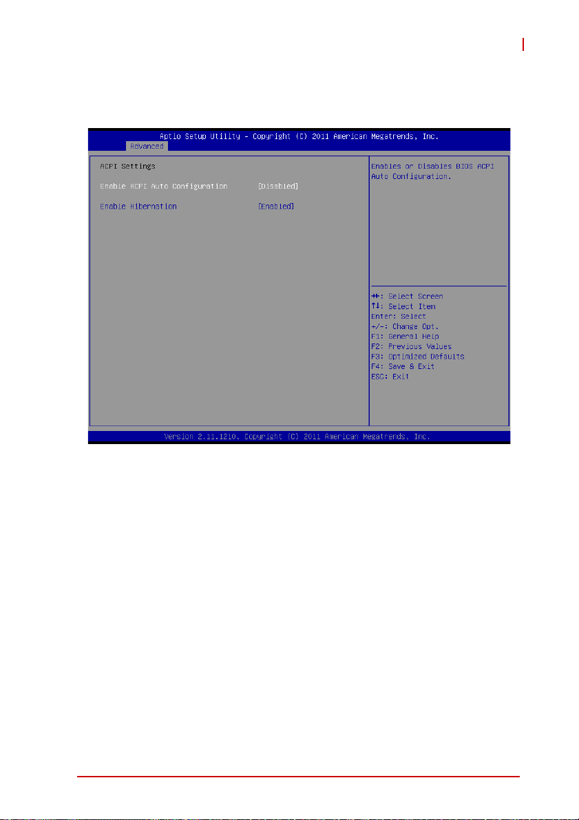
B.2.1 ACPI Settings
EOS-1200
Enable ACPI Auto Configuration
Enables or disables BIOS ACPI Auto Configuration.
Enable Hibernation
Enables or disables System ability to Hibernate. This option may
be not effective with some OS.
BIOS Setup 73
Page 86

B.2.2 CPU Configuration
Limit CPUID Maximum
Disabled for Windows XP
Execute Disable Bit
Enables XD to prevent certain classes of malicious buffer overflow attacks when combined with a supporting OS
Hardware Prefetcher
Enables or disables the Mid Level Cache(L2) streamer
prefetcher.
Adjacent Cache Line Prefetch
Enables or disables prefetching of adjacent cache lines.
74 BIOS Setup
Page 87

EOS-1200
Intel Virtualization Technology
When enabled, a VMM can utilize the additional hardware
capabilities provided by Vanderpool Technology
Local x2APIC
Enables Local x2APIC; some OS do not support this
EIST
Enables/Disables Intel SpeedStep Technology
Turbo Mode
Enables/Disables Intel TurboBoost Technology
C1E Function
When enabled, allows the CPU to enter enhanced C1 sleep
state to save more power than C1
CPU C3 Support
Enables/Disables CPU C3(ACPI C2) report to OS
CPU C6 Support
Enables/Disables CPU C6(ACPI C3) report to OS
CPU C7 Support
Enables/Disables CPU C7(ACPI C3) report to OS.
BIOS Setup 75
Page 88
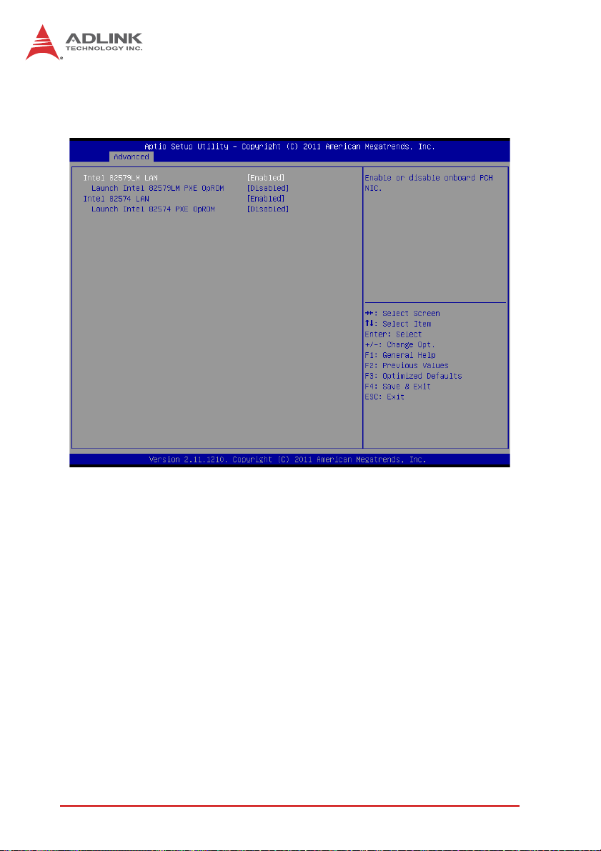
B.2.3 Onboard Device Configuration
Intel 82579LM LAN
Enables/Disables onboard Intel 82579LM (built-in PCH) Lan
controller
Launch Intel 82579LM LAN PXE OpROM
Enables/Disables execution of LAN boot-rom to add boot
option for legacy network devices
Intel 82574 LAN
Enables/Disables onboard Intel 82574 Lan controller
Launch Intel 82574 LAN PXE OpROM
Enables/Disables execution of LAN boot-rom to add boot
option for legacy network devices
76 BIOS Setup
Page 89

B.2.4 Advanced Power Management
EOS-1200
Restore On AC Power Loss
Determines the state the computer enters when power is restored
after a power loss. Options are Last State, Power On and Power
Off.
Option Description
Power Off When set, powers the system down when
power is restored.
Power On When set, powers the system up when
power is restored.
Last State When set, powers the system up or down
depending on the last state when power is
restored.
Table B-1: Restore On Power Loss Options
BIOS Setup 77
Page 90

Wake up system by 82579L LAN in S5
Enables or disables integrated LAN to wake the system in S5
state.
RTC Wakeup in S5
Enables or disables system wake on alarm event.
System watchdog
Enables or disables system internal watchdog to prevent boot
failure at system POST stage.
B.2.5 SATA Configuration
S-ATA Controller
Enables/ Disables Internal Serial ATA Controller 0.
SATA Mode
78 BIOS Setup
Page 91
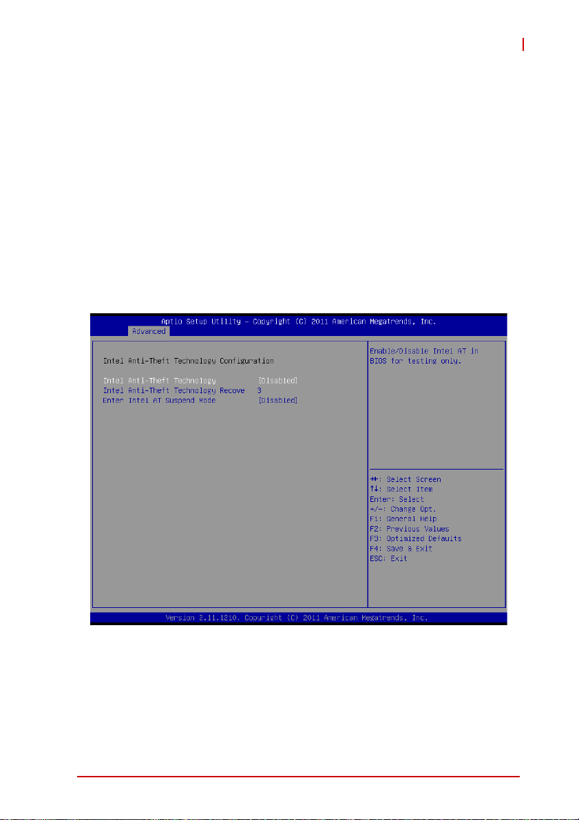
EOS-1200
This option selects the SATA channel configuration from (1) IDE
Mode (2) AHCI Mode or (3) RAID Mode.
Serial ATA Port 0~1, C-Fast Port, and E-SATA Port.
Port X
Enables or Disables SATA Port X
Hot Plug
Sets this port as hot pluggable.
B.2.6 Intel Anti-Theft Technology Configuration
Intel Anti-Theft Technology
Enables or disables Intel AT function. Intel
®
Anti-Theft Technology helps stop theft by rendering computers useless with
immediate shutdown
BIOS Setup 79
Page 92
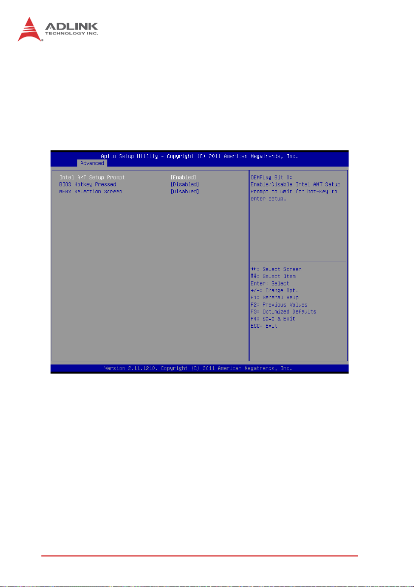
Intel Anti-Theft Technology Recovery/Enter Intel AT Suspend
Mode
Miscellaneous settings for Intel AT function
B.2.7 AMT Configuration
Intel AMT Setup Prompt
Enables or disables MEBx launch during system post for configuring AMT features
BIOS Hotkey Pressed/MEBx Selection Screen
Miscellaneous settings for iAMT function
80 BIOS Setup
Page 93

B.2.8 USB Configuration
EOS-1200
Legacy USB Support
Enables Legacy USB Support. AUTO option disables legacy
support if no USB devices are connected. DISABLE option will
keep USB devices available only for EFI applications.
USB3.0 Support
Enables or disables USB3.0 (XHCI) controller support, allowing
USB 3.0 devices to be used in DOS environment
XHCI Hand-Off
Enables BIOS support for XHCI Hands-Off feature. The default
option is Enabled.
BIOS Setup 81
Page 94

EHCI Hand-Off
Enables BIOS support on EHCI Hands-Off feature. The default
option is Enabled.
B.2.9 Super I/O Configuration
Serial Port 1 to 4 Configuration/Serial Port 5 Configuration
(Valid when PCB is changed)
Options in this configuration can enable/disable the port, select
a port type (RS-232/422/485) for Serial Port 1 and 2 only, or
change the port settings (address)
82 BIOS Setup
Page 95

EOS-1200
B.2.10 Hardware Monitor
PC Health Status
Hardware health on Super I/O monitors Board Temperature 1/
2, CPU Temperature, CPU Voltage, I-GFX Voltage, VCCSA
Voltage, +1.05V, +3.3V, +1.5V, +5V, +12.0V, VBAT, and Fan1/2
Speed.
Smart Fan 1/2 Mode
Sets the fan policy, supporting “Full on Mode”, in which the system fan (1/2) runs at full speed, “Manual Mode”, providing manual control of fan speed, and “Automatic Mode”, which controls
the system fan (1/2) according to a given fan policy
BIOS Setup 83
Page 96

B.2.11 Serial Port Console Redirection
COM 1 to 4, SOL (Serial Over LAN) COM
Console Redirection
Enables Console Redirection function on COM 1 to 4, SOL
COM
Console Redirection Settings
Sets miscellaneous parameters for COM Port 1 to 4, SOL
COM
B.2.12 Serial Port for Out-of-Band Management/EMS
Console Redirection
Enables Console Redirection function for remote management
of a Windows Server OS, via the port selected by Out-of-Band
Mgmt Port
84 BIOS Setup
Page 97

Out-of-Band Mgmt Port
Selects the COM Port for remote management of a Windows
OS
Terminal Type
Selects the transmission protocol for remote terminal console
B.3 Chipset
EOS-1200
BIOS Setup 85
Page 98

B.3.1 System Agent (SA) Configuration
VT-d
Enables VT-d function for efficient virtualization of I/O devices
Graphics Configuration
Selects the internal graphic device shared memory size and
power policy
86 BIOS Setup
Page 99

EOS-1200
Graphics Turbo IMON Current
Sets the maximum IMON current value for graphics turbo
mode
GTT Size
Selects the GTT size for internal graphics
DVMT Pre-Allocated
Selects DVMT 5.0 pre-allocated graphics memory size used by
the internal graphics device
DVMT Total Gfx Memory
Selects DVMT 5.0 total graphics memory size used by the
internal graphics device
BIOS Setup 87
Page 100

B.4 Boot
B.4.1 Boot Configuration
Setup Prompt Timeout
Number of seconds to wait for setup activation key (“DEL”)
Bootup NumLock State
Allows/disallows the NumLock setting to be modified during
boot
88 BIOS Setup
 Loading...