

Page 1
CSA-5200
2U Rackmount Network Appliance
with Intel® Xeon® Processor E3-1200 v3 Family
User’s Manual
Manual Revision: 1.01
Revision Date: November 25, 2014
Part No.: 50-1Z170-1010
Advance Technologies; Automate the World.
Page 2

CSA-5200
Revision History
Revision Release Date Description of Change(s)
1.00 18/08/2014 Initial release
1.01 25/11/2014 Remove CSA-5100; add French safety chapter
Copyright 2014 ADLINK Technology, Inc.
All Rights Reserved.
The information in this document is subject to change without prior notice in order to improve
reliability, design, and function and does not represent a commitment on the part of the
manufacturer.
In no event will the manufacturer be liable for direct, indirect, special, incidental, or
consequential damages arising out of the use or inability to use the product or
documentation, even if advised of the possibility of such damages.
This document contains proprietary information protected by copyright. All rights are
reserved. No part of this manual may be reproduced by any mechanical, electronic, or other
means in any form without prior written permission of the manufacturer.
Trademarks
Product names mentioned herein are used for identification purposes only and may be
trademarks and/or registered trademarks of their respective companies.
2
Page 3

CSA-5200
Table of Contents
Revision History................................................................................................................... 2
1 Overview .......................................................................................................................... 5
1.1 Introduction .............................................................................................................................. 5
1.2 Block Diagram.......................................................................................................................... 6
1.3 Mechanical Overview............................................................................................................... 7
1.3.1 Front Panel ........................................................................................................................................7
1.3.2 Rear Panel.........................................................................................................................................7
1.3.3 Chassis Layout ..................................................................................................................................8
1.4 Mechanical Dimensions ........................................................................................................... 9
1.4.1 Dimensions........................................................................................................................................9
1.5 Package Contents.................................................................................................................. 10
2 Specifications.................................................................................................................11
2.1 CSA-5200 Specifications ........................................................................................................11
2.2 Software Support ................................................................................................................... 12
2.3 Network Mezzanine Card Support ......................................................................................... 12
2.4 Optional Accessories ............................................................................................................. 12
3 Getting Started............................................................................................................... 13
3.1 Removing the Chassis Lid ..................................................................................................... 13
3.2 Installing the CPU/Heatsink ................................................................................................... 13
3.3 Installing a 3.5" SATA Drive.................................................................................................... 16
3.4 Installing a 2.5" SATA Drive.................................................................................................... 17
3.5 Installing a Network Interface Module.................................................................................... 18
3.6 Driver Installation ................................................................................................................... 20
4 System Interfaces.......................................................................................................... 21
4.1 Front Panel I/O....................................................................................................................... 21
4.1.1 Status LEDs.....................................................................................................................................21
4.1.2 LAN Connector (RJ-45) ...................................................................................................................21
4.1.3 Service Port Status LEDs ................................................................................................................22
4.1.4 USB 3.0 Connectors........................................................................................................................22
4.1.5 Remote Console Connector (RJ-45) ...............................................................................................22
4.2 Board Layout.......................................................................................................................... 23
4.3 Connectors and Jumpers....................................................................................................... 24
4.3.1 PCIe x4 Connector (PCIE1) ............................................................................................................24
4.3.2 CFast Connector (CN17).................................................................................................................25
4.3.3 VGA Header (CNX1) .......................................................................................................................25
4.3.4 ATX12V Connector (CN24) .............................................................................................................26
4.3.5 Fan Connectors (FAN1/FAN6-9) .....................................................................................................26
4.3.6 ATX Connector (CN19)....................................................................................................................26
4.3.7 mSATA Connectors (CN9/CN48).....................................................................................................27
4.3.8 SATA Connectors (CN30-33)...........................................................................................................27
4.3.9 SATADOM Power Connector (CN18, Wafer 1.25mm pitch)............................................................28
4.3.10 Clear CMOS Jumper (JBAT1) .......................................................................................................28
4.3.11 NIM Slot connectors (PCI1-4)........................................................................................................28
5 LAN Bypass Function................................................................................................... 30
5.1 Hardware Description ............................................................................................................ 30
5.2 BIOS Settings ........................................................................................................................ 31
5.3 SuperIO Watchdog Driver & API ............................................................................................ 32
5.3.1 Overview..........................................................................................................................................32
3
Page 4

CSA-5200
6 Watchdog Timer Programming .................................................................................... 34
6.1 Architecture Overview............................................................................................................ 34
6.2 Deliverables ........................................................................................................................... 35
6.2.1 open.................................................................................................................................................35
6.2.2 write .................................................................................................................................................35
6.2.3 ioctl ..................................................................................................................................................36
6.2.4 release .............................................................................................................................................37
6.3 Sample Code ......................................................................................................................... 37
7 BIOS Setup..................................................................................................................... 40
7.1 Entering BIOS Setup.............................................................................................................. 40
7.2 Setup Menu............................................................................................................................ 41
7.3 Navigation .............................................................................................................................. 41
7.4 Main Setup............................................................................................................................. 44
7.4.1 System & Board Info........................................................................................................................44
7.4.2 System Date/System Time ..............................................................................................................45
7.5 Advanced BIOS Setup ........................................................................................................... 45
7.5.1 ACPI Settings ..................................................................................................................................46
7.5.2 CPU Configuration...........................................................................................................................46
7.5.3 SATA Configuration..........................................................................................................................48
7.5.4 PCH-FW Configuration....................................................................................................................49
7.5.5 USB Configuration...........................................................................................................................49
7.5.6 Super IO Configuration....................................................................................................................50
7.5.7 IT8786 HW Monitor .........................................................................................................................51
7.5.8 Smart Fan Function .........................................................................................................................52
7.5.9 Serial Port Console Redirection ......................................................................................................53
7.6 Chipset Setup ........................................................................................................................ 56
7.6.1 PCH-IO Configuration......................................................................................................................56
7.6.2 System Agent (SA) Configuration....................................................................................................58
7.7 Boot Setup ............................................................................................................................. 61
7.8 Security Setup........................................................................................................................ 62
7.9 Save & Exit Menu .................................................................................................................. 63
Safety Instructions............................................................................................................. 66
Consignes de Sécurité Importantes ................................................................................. 67
Getting Service................................................................................................................... 68
4
Page 5

CSA-5200
1 Overview
1.1 Introduction
The ADLINK CSA-5200 is a 2U 19" rackmount Network Appliance with 4th Generation Intel®
processor Xeon® E3-1200 v3 and Intel® C226 Chipset. The CSA-5200 features up to 32x
GbE ports or 8x SFP+ with an I/O intensive architecture, high scalability with four Network
Interface Module (NIM) slots, 2.5’’/3.5’’ SATA drive bays, additional storage interfaces
(SATADOM, CFast), and is an ideal platform for communications infrastructure deployment.
Detailed features are outlined below and a functional block diagram is shown in the next
section.
4th Gen Intel® processor Xeon® E3-1200 v3 with Intel® C226 Chipset
• Intel® Xeon® E3-1275 v3 (4C/8T)
• Intel® Xeon® E3-1225 v3 (4C/4T)
• Intel® Core™ i3-4330 (2C/4T)
8MB/4M/3M/2M L2 cache, depending on CPU
4x DDR3-1066/1333/1600 240-pin DIMM sockets, non-ECC, up to 32 GB
Up to 32x GbE ports or 8x SFP+ with I/O intensive architecture
High scalability with four Network Interface Module (NIM) slots
Four 2.5’’/3.5’’ SATA drive bays
Additional storage interfaces: SATADOM, CFast
2U 19’’ rackmount form factor for communications infrastructure deployment
5
Page 6
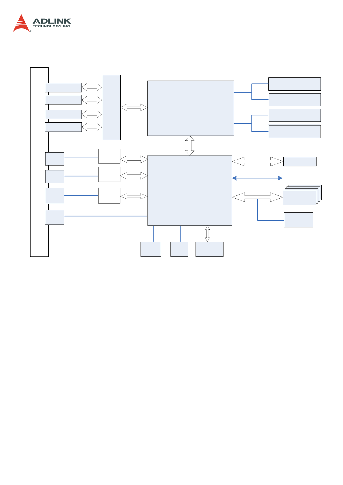
1.2 Block Diagram
CSA-5200
UDIMM
DDR3 1600MHz
UDIMM
DDR3
1600MHz
UDIMM
1600MHz
DDR3
UDIMM
1600MHz
DDR3
BIOS
to NIM slots
2.5/3.5" SATA
or mSATA
SATADOM
F
R
O
N
T
P
A
N
E
L
NIM slot
(PCIe x8, GPIO)
NIM slot
(PCIe x8, GPIO)
NIM slot
(PCIe x8, GPIO)
NIM slot
(PCIe x8, GPIO)
RJ-45
GbE
RJ-45
GbE
RJ-45
COM
USB 3.0
x2
1000M MDI+/-
1000M MDI+/-
PCIe Switch
Intel
I211AT
Intel
I211AT
Super
IO
PCIe 3.0 x16
PCIe x 1
PCIe x 1
LPC
VGA
VGA
header
Intel®Xeon®
E3-1200 v3
DMI 2.0 x4
Intel PCH
C226
SATA
CFast
socket
PCIe x4
socket
SPI
GPIO
SATA x4
PCIe 2.0 x4
6
Page 7
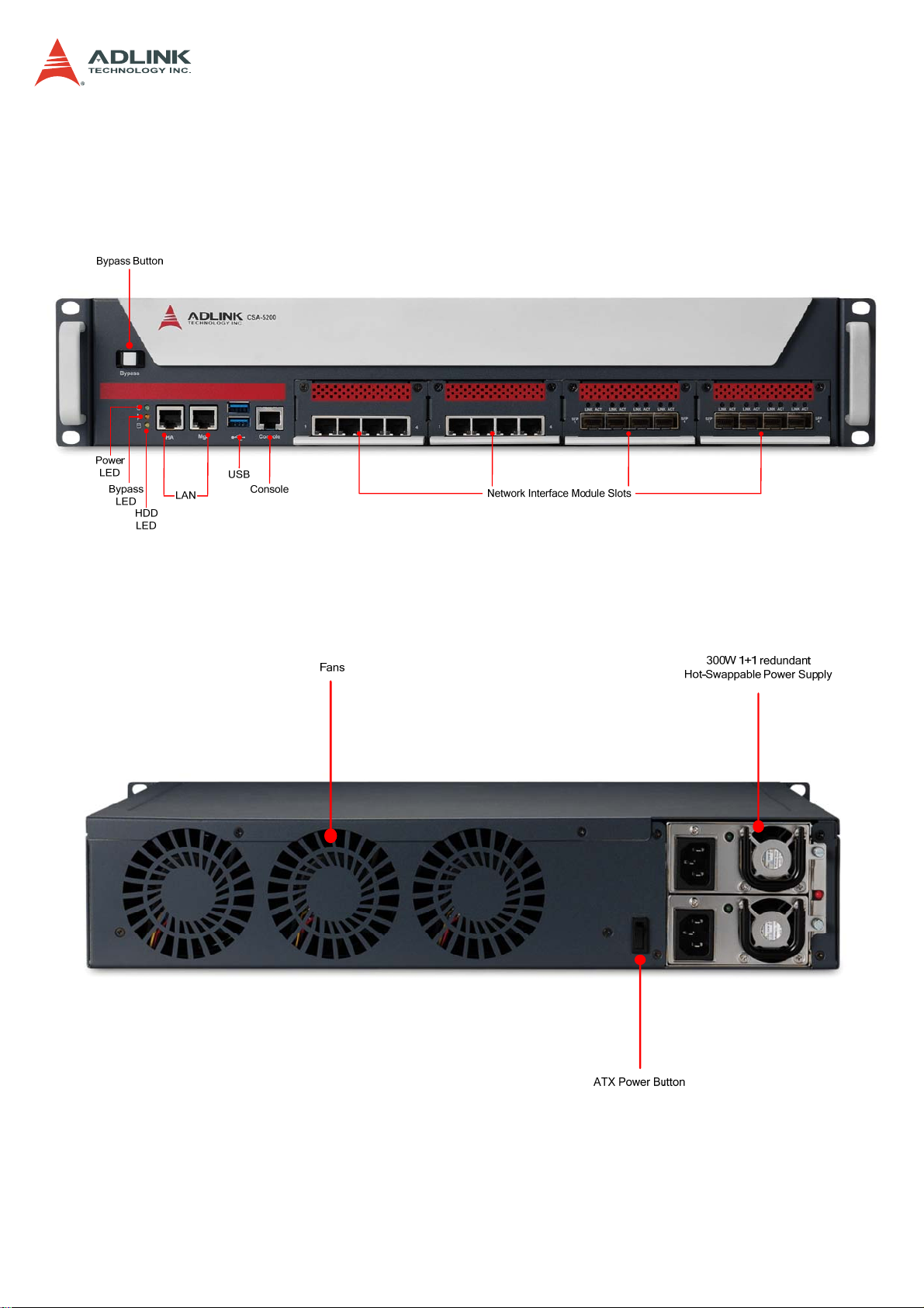
1.3 Mechanical Overview
1.3.1 Front Panel
CSA-5200
1.3.2 Rear Panel
7
Page 8
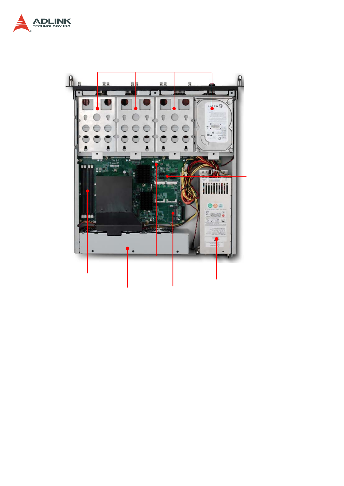
1.3.3 Chassis Layout
CSA-5200
SATA Drive Bays
DDR3 DIMMs x4
SATADOM
Fans
Power
CFast
SATA
Connectors
Power Supply
8
Page 9
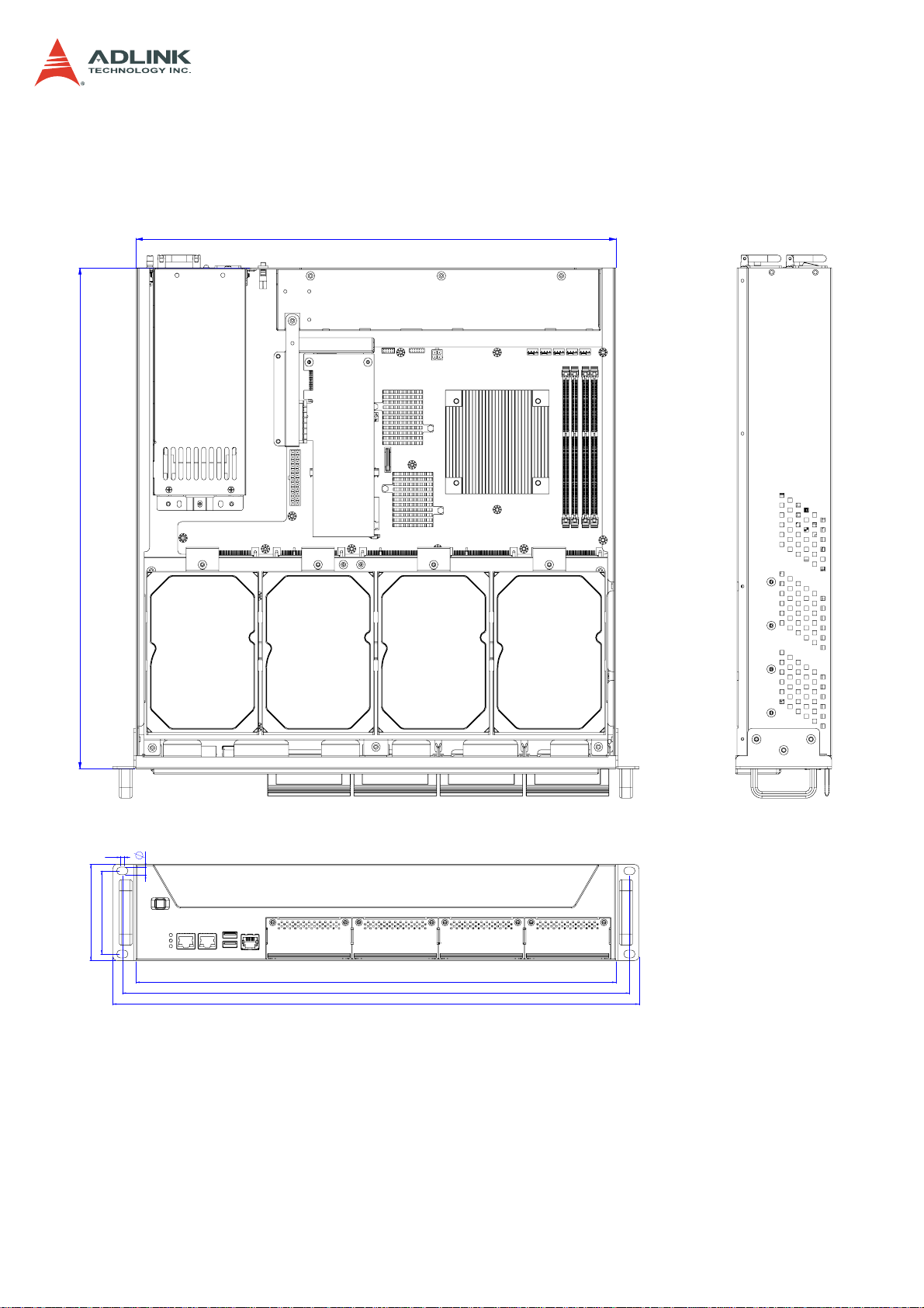
1.4 Mechanical Dimensions
1.4.1 Dimensions
440
CSA-5200
458.8
7
3.3
88
76.2
Dimensions in mm
440
465
482.6
9
Page 10

CSA-5200
1.5 Package Contents
Before opening, please check the shipping carton for any damage. If the shipping carton and
contents are damaged, notify the dealer for a replacement. Retain the shipping carton and
packing material for inspection by the dealer. Obtain authorization before returning any
product to ADLINK.
Check that the following items are included in the package. If there are any missing items,
contact your dealer:
CSA-5200 Rackmount Network Appliance
VGA cable (pin header to DB-15)
Remote console cable (RJ-45 to DB-9)
Accessory pack (drive bracket mounting hardware)
Power cord
ADLINK All-In-One CD
10
Page 11
2 Specifications
2.1 CSA-5200 Specifications
Main System
CPU
Intel® Xeon® E3-1275 v3 (4C/8T)
Intel® Xeon® E3-1225 v3 (4C/4T)
Intel® Core™ i3-4330 (2C/4T)
CSA-5200
L2 Cache
Chipset
Memory
BIOS
Operating Systems
Power Supply
8MB/8MB/4MB
Intel® C226 PCH
Four DDR3-1066/1333/1600 * 240-Pin Long-DIMM sockets, nonECC, up to 32 GB
AMI BIOS on SPI flash memory
Windows 7 64bit, Linux kernel 2.6 and above
(default: no OS installed)
300W AC 1+1 redundant (hot-swappable)
I/O Interfaces - Front
NIM Slots
Ethernet
Remote Console
USB
4x Network Interface Module (NIM) slots
2x RJ-45 10/100/1000BASE-T Ethernet port
1x RJ-45 serial port
2x USB 3.0
I/O Interfaces - Onboard
Security Acceleration
Graphics
1x PCIe x4 Gen2 socket for acceleration card
1x VGA header onboard
Storage
Drive Bays
4x 2.5” or 3.5” SATA drive bays
Other
*Note: *SATADOM shares SATA port with drive bays.
1x SATADOM*, 1x CFast socket
Buttons/LEDs
Power
Bypass
LEDs
1x ATX power button, rocker type (rear)
1x bypass button (front)
Power, Bypass Status, Drive Activity
11
Page 12
Mechanical & Environmental
Form Factor
19” 2U rackmount 440mm x 88mm x 460 mm (W x H x D)
CSA-5200
Fans
Power
Temperature
Humidity
Shock
Vibration
Acoustic Level
Certifications
MTBF
3x fans speed adjustable
Able to operate with 1 fan out of service
300W, 100V-240VAC @ 50/60 Hz, full range, 1+1 redundant, hot
swappable
Operating temp.: 0°C -40°C
Storage temp.: -40°C to 70°C
Short term operating: -5°C to +45°C (5%-90% rel. humidity)
Operating: 20% - 90% @40°C, non-condensing
Storage: 5% - 90%, non-condensing
Operating: half-sine 2G, 11ms pulse, 100 pulses in each direction,
on each of three axes
Non-operating: trapezoidal, 25G, 170 inches/sec delta V, three
drops in each direction, on each of three axes
Non-operating: 2.2Grms, 10 minutes per axis on all three axes
Sound pressure < 75 dBA @1m with all fans at maximum speed
FCC Class A, CE emissions, UL, CB and RoHS compliant
50,000 hours
2.2 Software Support
ADLINK DPDK
Toolkit
ADLINK DPI Toolkit
ADLINK Load
Balancing Toolkit
Enables Intel® DPDK
Intel® DPDK-based openDPI to boost DPI performance
Intel® DPDK vSwitch-based Load Balancer
2.3 Network Mezzanine Card Support
CSA-Z4X01
CSA-Z5C4F
CSA-Z8X10
CSA-Z5C2F
4-port GbE copper with LAN bypass PN: 91-37584-100E
4-port GbE SFP without LAN bypass PN: 91-37585-000E
8-port GbE copper with LAN bypass PN: 91-37588-000E
2-port SFP+ without LAN bypass PN: 91-37589-000E
2.4 Optional Accessories
Riser Card
Riser card for PCIe x4 acceleration card PN: 91-37591-000E
12
Page 13
3 Getting Started
3.1 Removing the Chassis Lid
1. Remove the four screws securing each side of the lid to the chassis.
2. Remove the two screws securing the rear of the lid to the chassis.
3. Slide the lid to the rear and remove from the chassis.
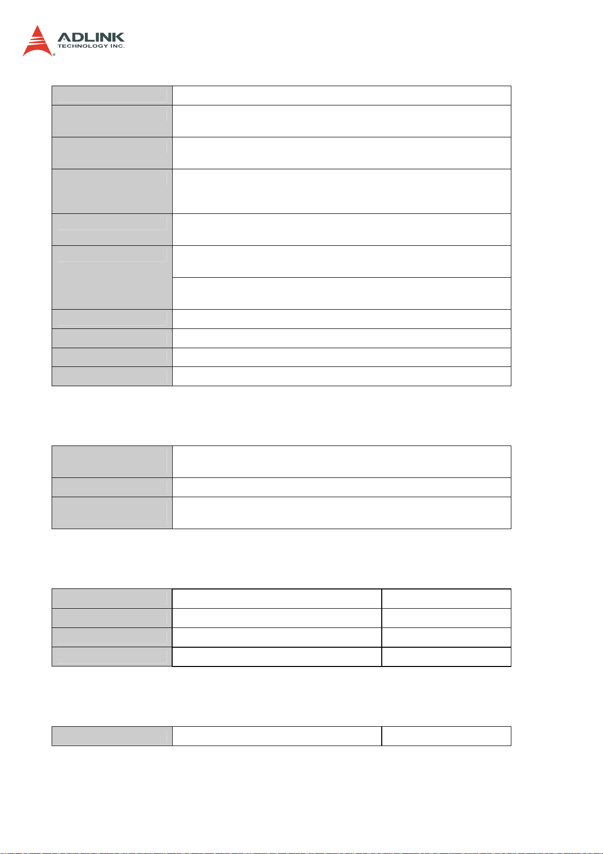
3.2 Installing the CPU/Heatsink
1. Locate the CPU sockets on the board.
2. Press the load lever, move it outwards until it is clear of the retention tab, then raise it
CSA-5200
3. Open the load plate and remove the protective cover from the socket. Do not touch
the socket contacts or the bottom of the processor.
13
Page 14
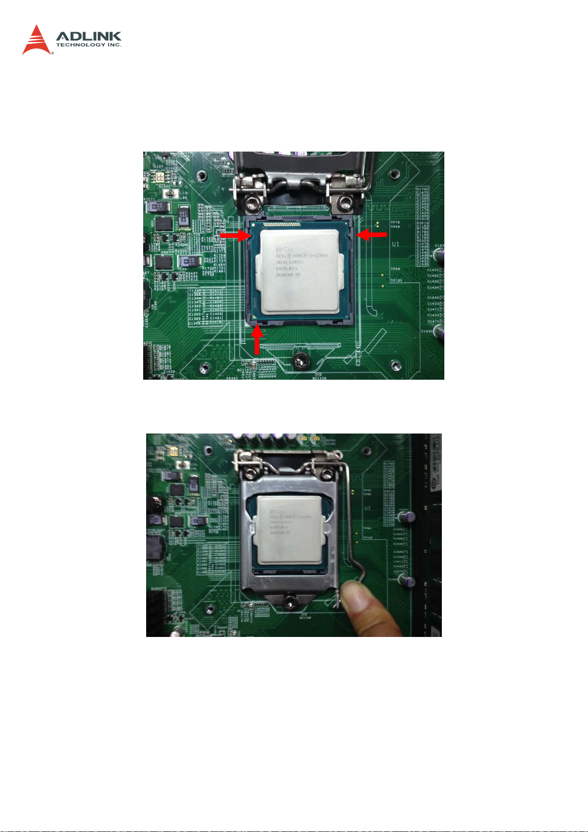
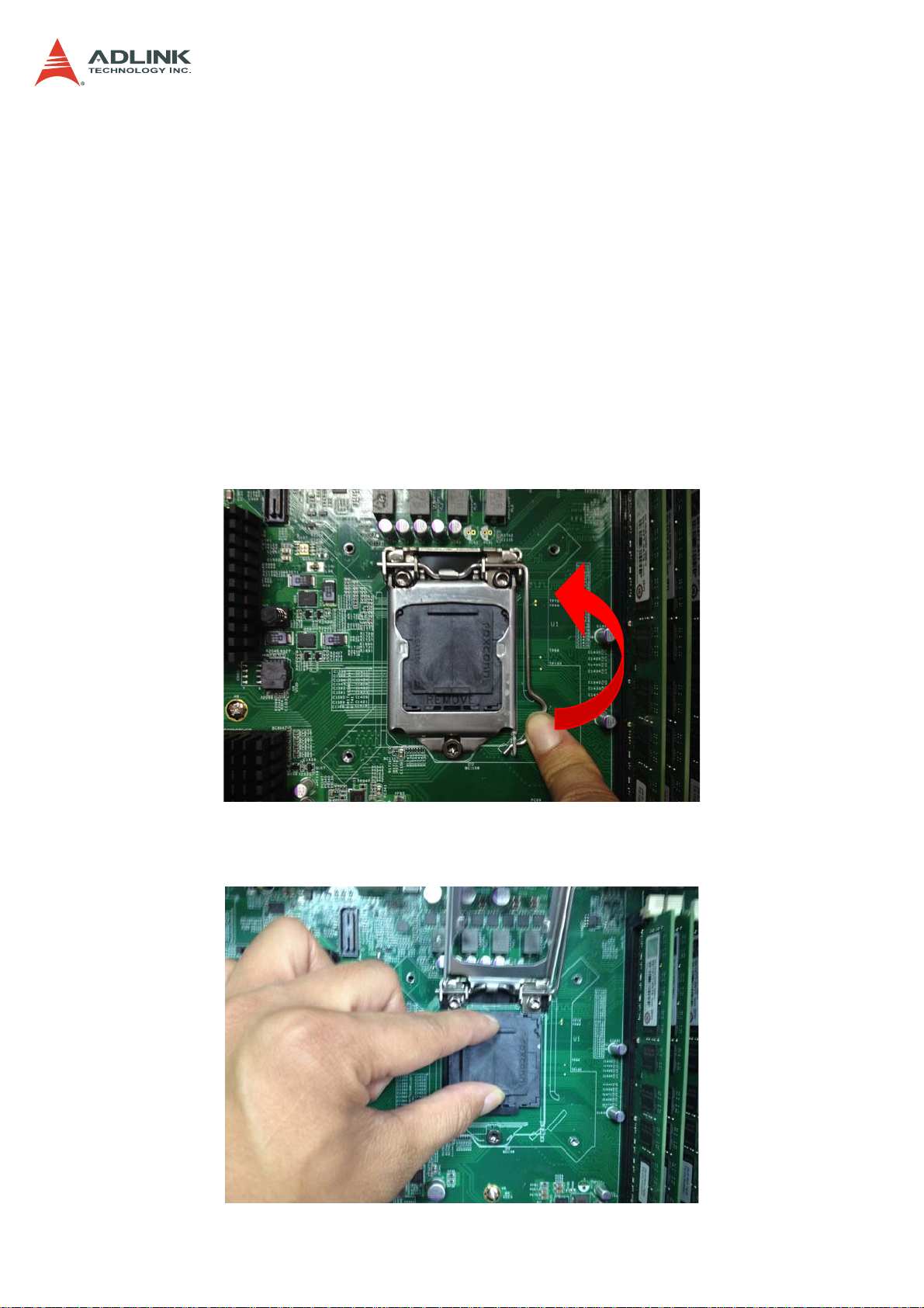
4. Carefully place the CPU into the socket, making sure the socket notches align with
the processor notches and the alignment triangle on the CPU lines up with the correct
corner on the socket,. Lower the processor straight down, without tilting or sliding the
processor in the socket. Gently release the processor, making sure that it is seated
correctly in the socket.
CSA-5200
5. Close the load plate, push the load lever back down, and engage it with the retention
tab.
14
Page 15
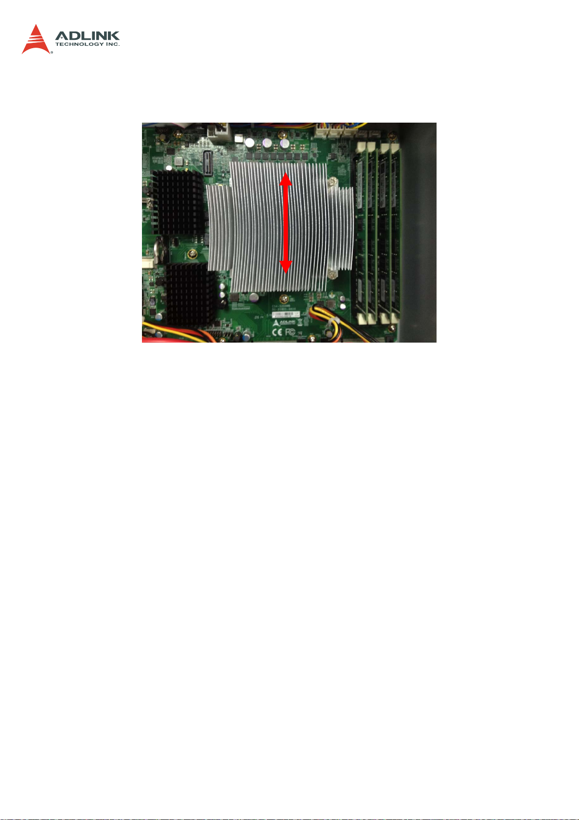
6. Make sure there is sufficient thermal paste on of the heatsink and place it on the CPU
with the cooling fins aligned with the DIMM slots as shown.
CSA-5200
7. Tighten the captive screws in an "X" pattern until the heatsink is secured on the CPU.
Do NOT over tighten the screws
15
Page 16
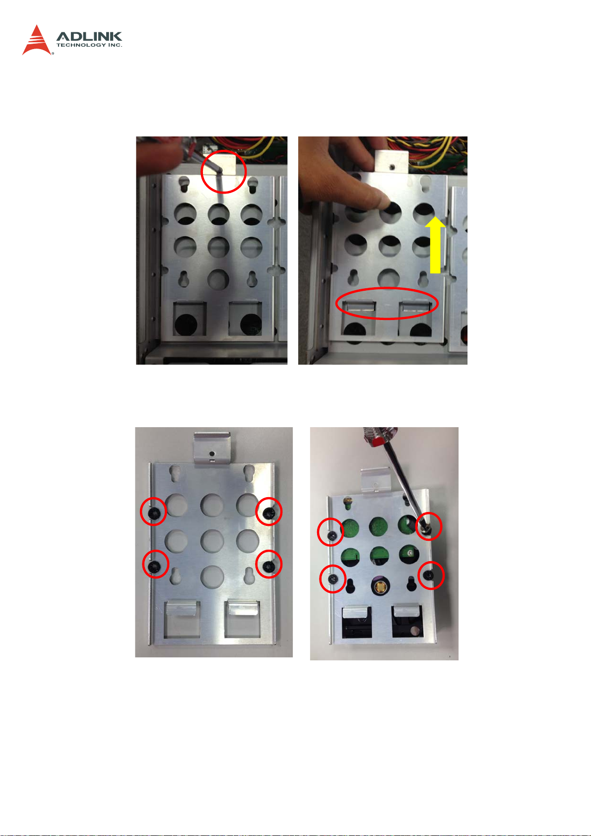
3.3 Installing a 3.5" SATA Drive
1. Loosen the screw securing the drive bracket to the chassis and lift the bracket out as
shown.
2. Insert the anti-shock grommets provided in the accessory pack as shown, and secure
the 3.5" SATA drive to the bracket with four screws.
CSA-5200
16
Page 17
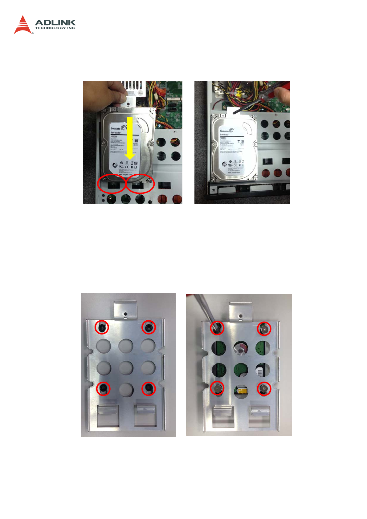
3. Install the drive/bracket assembly to the chassis, making sure the 2 tabs of the
bracket fit into the slots as shown.
CSA-5200
3.4 Installing a 2.5" SATA Drive
1. Remove the drive bracket as described above, and install the anti-shock grommets as
shown. Secure the 2.5" SATA drive to the bracket with four screws.
2. Install the drive/bracket assembly to the chassis as described above for 3.5" drives.
17
Page 18
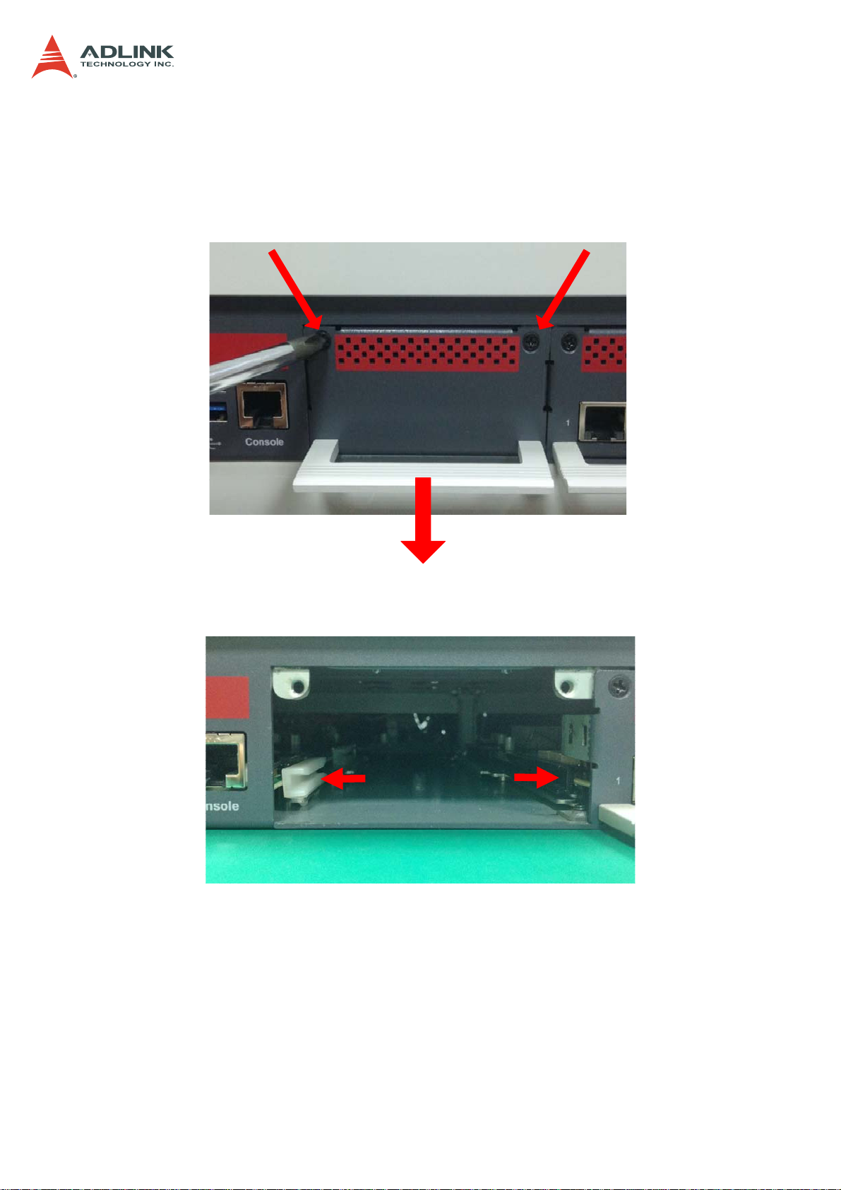
3.5 Installing a Network Interface Module
3. Loosen the two screws on the Network Interface Module (NIM) faceplate, and pull
outwards on the handle to remove the faceplate.
CSA-5200
4. Align the NIM with the card guides in the slot as shown below.
18
Page 19
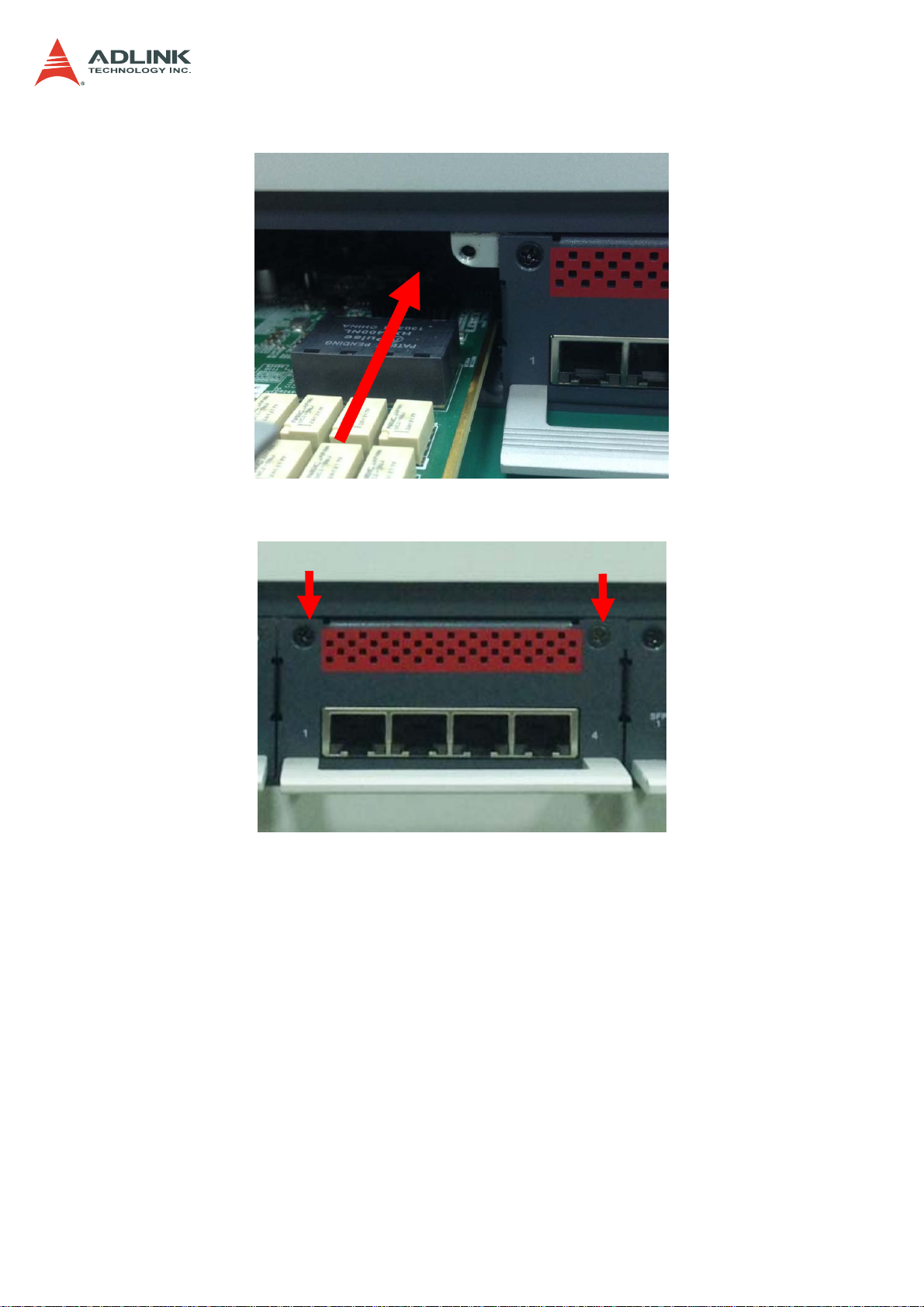
5. Insert the NIM into the slot.
6. Secure the NIM with the two screws removed in Step 1.
CSA-5200
19
Page 20

CSA-5200
3.6 Driver Installation
The CSA-5200 drivers are available from the ADLINK All-In-One DVD at X:\CSA-5200\, or
from the ADLINK website at: http://www.adlinktech.com/PD/web/PD_detail.php?cKind
=&pid=1429.
ADLINK provides validated drivers for Windows 7 64-bit. We recommend using these drivers
to ensure compatibility.
The following describes the CSA-5200 driver installation procedures for Windows 7. Install
the Windows operating system before installing any driver. Most standard I/O device drivers
are installed during Windows installation.
1. Install the chipset driver by extracting and running the program in ...
\Driver_Infinst_autol\ infinst_autol.zip
2. Install the graphics driver and utilities by extracting and running the program in ...
\Graphics_Driver_WIN7_64bit\ graphic_win64_10.18.10.3496.zip.
3. Install the LAN driver by running the program in …\LAN_Win7\PROWinx64.zip.
4. Install the Intel Management Engine and utilities by extracting and running the
program in …\Intel_ME9.1_5M\ Intel_ME9.1_5M_9.1.0.1035.zip.
5. Install the Intel Rapid Storage Technology utility by extracting and running the
program in …\Intel Rapid Storage Technology\irst_12.5.0.1040.zip.
6. Install the USB 3.0 driver by running the program in …
\USB_3.0_Win7\ USB_3.0_Win7_2.5.1.28.zip.
20
Page 21
4 System Interfaces
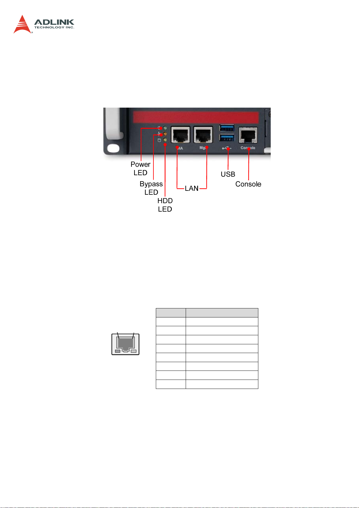
4.1 Front Panel I/O
CSA-5200
4.1.1 Status LEDs
Power LED Green: Power On
Bypass Status LED Red: Bypass; Off: No Bypass
HDD Activity LED Flashing Yellow: Read/Write; Off: No activity
4.1.2 LAN Connector (RJ-45)
8
1
Left
LED
Right
LED
Pin Signal
1 MID0+
2 MID03 MID1+
4 MID2+
5 MID26 MID17 MID3+
8 MID3-
21
Page 22

4.1.3 Service Port Status LEDs
LAN LED Status LED Color
10 Mbps Off
100 Mbps GREEN
1000 Mbps Yellow
LINK with no activity Green
LINK up Yellow
Link down Off
LINK down or Link
with no activity
LINK with activity Green Blinking
GbE
SFP/SFP+
Left
Right
Right
Left
Right
4.1.4 USB 3.0 Connectors
CSA-5200
Off
Pin Signal
1 P5V_USB3
2 S_USB2_N0_R
3 S_USB2_P0_R
4 GND
5 S_USB3_RN1_R
6 S_USB3_RP1_R
7 GND
8 S_USB3_TN1_R
9 S_USB3_TP1_R
4.1.5 Remote Console Connector (RJ-45)
8
1
Pin Signal
1 DCD-L_CN
2 RTS-L_CN
3 DSR-L_CN
4 TXD_CN
5 RXD_CN
6 GND
7 CTS-L_CN
8 DTR-L_CN
22
Page 23

4.2 Board Layout
CSA-5200
34 5
1
2
77
10
6
8
9
11 11 11 11
Location Description Location Description
1
2
3
4
5
6
PCIe x4 connector (PCIE1)
CFast connector (CN17)
VGA header (CNX1)
ATX12V connector (CN24)
Fan connectors (FAN1/FAN6-9)
ATX connector (CN19)
7
8
9
10
11
mSATA connectors (CN9/CN48)
SATA connectors (CN30-33)
SATADOM power connector (CN18)
Clear CMOS jumper (JBAT1)
NIM slot connectors (PCI1-4)
SATA connector CN32 is shared with SATADOM.
23
Page 24

4.3 Connectors and Jumpers
4.3.1 PCIe x4 Connector (PCIE1)
Pin Signal Pin Signal
A1 PRSNT1#
A2 +12V
A3 +12V
A4 GND
A5 JTAG2
A6 JTAG3
A7 JTAG4
A8 JTAG5
A9 +3.3V
A10 +3.3V
A11 PERST#
A12 GND
A13 REFCLK+
A14 REFCLKA15 GND
A16 PERp0
A17 PERn0
A18 GND
A19 RSVD
A20 GND
A21 PERp1
A22 PERn1
A23 GND
A24 GND
A25 PERp2
A26 PERn2
A27 GND
A28 GND
A29 PERp3
A30 PERn3
A31 GND
A32 RSVD
B1
B2
B3
B4
B5
B6
B7
B8
B9
B10
B11
B12
B13
B14
B15
B16
B17
B18
B19
B20
B21
B22
B23
B24
B25
B26
B27
B28
B29
B30
B31
B32
CSA-5200
+12V
+12V
+12V
GND
SMCLK
SMDAT
GND
+3.3V
JTAG1
3.3Vaux
WAKE#
RSVD
GND
PETp0
PETn0
GND
PRSNT2#
GND
PETp1
PETn1
GND
GND
PETp2
PETn2
GND
GND
PETp3
PETn3
GND
RSVD
PRSNT2#
GND
24
Page 25

4.3.2 CFast Connector (CN17)
CSA-5200
Pin Signal
S1 GND
S2 CF_TX_DP
S3 CF_TX_DN
S4 GND
S5 CF_RX_DN
S6 CF_RX_DP
S7 GND
P1 CFast_CDI
P2 GND
P3 NC
P4 NC
P5 NC
P6 NC
P7 NC
P8 GND
P9 NC
P10 NC
P11 NC
P12 NC
P13 P3V3
P14 P3V3
P15 GND
P16 GND
P17 CFast_CDO
4.3.3 VGA Header (CNX1)
2
1
Pin Signal
1 S_DDC_DATA_R
2 S_DDC_CLK_R
3 S_VGA_RED_CONN
4 S_VGA_GREEN_CONN
5 S_VGA_BLUE_CONN
6 S_VGA_HSYNC
7 S_VGA_VSYNC
8 VGA_VCC
9 NC
10-14 GND
25
Page 26

4.3.4 ATX12V Connector (CN24)
Pin Signal
2
1
1-4
5-8 P12V_CORE
4.3.5 Fan Connectors (FAN1/FAN6-9)
CSA-5200
GND
1
4.3.6 ATX Connector (CN19)
Pin Signal Pin Signal
13
1
1 +3.3V 13 +3.3V
2 +3.3V 14 -12V
3 GND 15 GND
4 +5V 16 ATX_PSON#
5 GND 17 GND
6 +5V 18 GND
7 GND 19 GND
8 F_PWRGD_PS 20 NC
9 P5VSB 21 +5V
10 +12V 22 +5V
11 +12V 23 +5V
12 +3.3V 24 GND
Pin Signal
1 FAN_CTL
2 FAN_TAC
3 P12V_CORE
4 GND
26
Page 27

4.3.7 mSATA Connectors (CN9/CN48)
Pin Signal Pin Signal
1 NC 2 P3V3
1
3 NC 4 GND
5 NC 6 P1V5
7 NC 8 NC
9 GND 10 NC
11 NC 12 NC
13 NC 14 NC
1
2
15 GND 16 NC
17 NC 18 GND
19 NC 20 NC
21 NC 22 NC
23 RXP0_R 24 P3V3
25 RXN0_R 26 GND
27 GND 28 P1V5
29 GND 30 NC
31 TXN0_R 32 NC
33 TXP0_R 34 GND
35 GND 36 NC
37 GND 38 NC
39 P3V3 40 GND
41 P3V3 42 NC
43 NC 44 NC
45 NC 46 NC
47 NC 48 P1V5
49 NC 50 GND
51 NC 52 P3V3
CSA-5200
4.3.8 SATA Connectors (CN30-33)
Pin Signal
1 Ground
1
CN32 is shared with SATADOM.
2 TXP
3 TXN
4 Ground
5 RXN
6 RXP
7 Ground
27
Page 28

CSA-5200
4.3.9 SATADOM Power Connector (CN18, Wafer 1.25mm pitch)
Pin Signal
1 Ground
2 TXP
3 TXN
4 Ground
1
4.3.10 Clear CMOS Jumper (JBAT1)
1
Short Pins Function
1-2 Normal
2-3 Clear CMOS
4.3.11 NIM Slot connectors (PCI1-4)
Pin Signal Pin Signal
2
1
A1
A2
A3
A4
A5
A6
A7
A8
A9
A10
A11
A12
A13
A14
A15
A16
A17
A18
A19
A20
A21
A22
A23
A24
A25
A26
A27
A28
BYPASS_LAN1# B1 PWR_IO (5V)
PWR_IO (5V) B2 PWR_IO (5V)
PWR_IO (5V) B3 PWR_IO (5V)
GND B4 GND
NC B5 LAN_SMB_CLK`
NC B6 LAN_SMB_DATA
NC B7 GND
NC B8 P3V3
P3V3 B9 NC
P3V3 B10 P3V3_DUAL
PLT_RESET_PCIE# B11 PULL P3V3_DUAL
GND B12 NC
C_100M_NMC_N B13 GND
C_100M_NMC_N B14 PCIE-TXP0
GND B15 PCIE-TXN0
PCIE-RXP0 B16 GND
PCIE-RXN0 B17 NC
GND B18 GND
NC B19 PCIE-TXP1
GND B20 PCIE-TXN1
PCIE-RXP1 B21 GND
PCIE-RXN1 B22 GND
GND B23 PCIE-TXP2
GND B24 PCIE-TXN2
PCIE-RXP2 B25 GND
PCIE-RXN2 B26 GND
GND B27 PCIE-TXP3
GND B28 PCIE-TXN3
28
Page 29

Pin Signal Pin Signal
A29
A30
A31
A32
A33
A34
A35
A36
A37
A38
A39
A40
A41
A42
A43
A44
A45
A46
A47
A48
A49
PCIE-RXP3 B29 GND
PCIE-RXN3 B30 NC
GND B31 NC
NC B32 GND
NC B33 PCIE-TXP4
GND B34 PCIE-TXN4
PCIE-RXP4 B35 GND
PCIE-RXN4 B36 GND
GND B37 PCIE-TXP5
GND B38 PCIE-TXN5
PCIE-RXP5 B39 GND
PCIE-RXN5 B40 GND
GND B41 PCIE-TXP6
GND B42 PCIE-TXN6
PCIE-RXP6 B43 GND
PCIE-RXN6 B44 GND
GND B45 PCIE-TXP7
GND B46 PCIE-TXN7
PCIE-RXP7 B47 GND
PCIE-RXN7 B48 NC
GND B49 GND
NIM Slot connectors (PCI1-4) (con'td)
CSA-5200
29
Page 30

CSA-5200
5 LAN Bypass Function
The CSA-5200 is equipped with a LAN Bypass function to allow uninterrupted network traffic
in the case of power disruption, system failure, or if a single in-line appliance is shut down or
hangs. The default behaviour of the LAN Bypass function is determined by BIOS setting
Under the following conditions, GPIO signals trigger the LAN bypass mechanism:
• Bypass button on front panel is pushed when the system is powered on.
• System crash occurs (after reboot with Watchdog Timer is running under Linux)
• System is powered on but not running OS (if enabled in BIOS)
• After booting into OS (if enabled in BIOS and Watchdog Timer is not running under
Linux)
• Power turned off or disconnected
5.1 Hardware Description
The CSA-5200 can bypass the LAN port on designated NIMs (CSA-Z4X01, CSA-Z8X10).
1
2
CSA-5200 LAN Bypass Hardware Layout
(1) Bypass Button:
Enable/Disable LAN bypass by pushing the Bypass Button when the system is
powered on.
(2) Bypass LED (middle LED) :
Red: Bypass enabled
Off: Bypass disabled
(3) LAN Bypass Port Pairing (CSA-Z4X01)
LAN Bypass Pair 1: LAN1 & LAN2
LAN Bypass Pair 2: LAN3 & LAN4
3
30
Page 31

CSA-5200
CSA-Z8X10 LAN Bypass Port Pairing
LAN Bypass Pair 1: LAN1 & LAN2
LAN Bypass Pair 2: LAN3 & LAN4
LAN Bypass Pair 3: LAN5 & LAN6
LAN Bypass Pair 4: LAN7 & LAN8
5.2 BIOS Settings
The default behaviour of the CSA-5200's LAN Bypass function is set in the BIOS.
• Bypass Enabled: LAN Bypass is enabled until the system boots into OS and is
disabled by software control or by pushing the Bypass Button.
• Bypass Disabled: LAN Bypass is disabled until the system boots into OS and is
enabled by software control or by pushing the Bypass Button.
The LAN Bypass BIOS setting is set by entering the BIOS setup menu: Advanced > LAN
Bypass Configuration > LAN Bypass Setting, choose "Bypass" or "No Bypass". The BIOS
factory default setting is "No Bypass".
31
Page 32

CSA-5200
5.3 SuperIO Watchdog Driver & API
A SuperIO Watchdog Driver and API (Linux only) is available to enable LAN bypass by
software control and to reboot the system when a crash occurs (LAN bypass can be enabled
on system restart). To make use of this feature, first install a Linux OS, and then install the
SuperIO Watchdog Driver.
5.3.1 Overview
A Watchdog Timer (WDT) is a hardware circuit that can reset the computer system in case of
a software fault. Usually a user space daemon will notify the kernel watchdog driver via the
/dev/watchdog special device file that user space is still alive, at regular intervals. When such
a notification occurs, the driver will usually tell the hardware watchdog that everything is in
order, and that the watchdog should wait for period of time to reset the system. If user space
fails (RAM error, kernel bug, etc.), the notifications cease to occur, and the hardware
watchdog will reset the system (causing a reboot) after the timeout occurs.
The figure below depicts all logical blocks in the CSA-5200 SuperIO watchdog
implementation.
32
Page 33

CSA-5200
CSA-5200
Haswell CPU
BYPASS_BTN#
BYPASS_LAN#
PCH
RESET
WDOG_CTRL
LPC
Watchdog
(ITE IT8786)
LAN IN
LAN[1,2,3,4]
BYPASS_BTN#
LAN_BYPASS_LED#
Active Low
(Implemented by
HW)
Network
Controller
WDOG_REEST
LAN OUT
Logical Blocks in the Watchdog Implementation
The watchdog is controlled by writing to the SuperIO registers. The BYPASS_LAN# signal
will indicate whether LAN bypass is activated. When the BYPASS_LAN# output is 0 (activelow), the CSA-5200 hardware will bypass the LAN inputs (LAN1, LAN2, LAN3, LAN4). When
the BYPASS_LAN# output is 1 (inactive), the CSA-5200 hardware will take in the LAN inputs
for IP package inspection and security processing. The various pin functions are described
as follows.
• BYPASS_BTN#: issue a low pulse after the button is pushed. The BIOS routine will
read the bypass button status, then trigger BYPASS_LAN# when the button is
pushed. Linux watchdog software need NOT handle the BYPASS_BTN#.
• BYPASS_LAN#: active low. Both BIOS and Linux watchdog software can read and
change this GPIO status. LAN bypass is activated when BYPASS_LAN# is set to 0
(active-low).
• WDOG_CTRL: LPC bus. Both BIOS and Linux can control the SuperIO watchdog by
writing its registers over LPC bus.
• WDOG_RESET: issue low pulse when feeding fails. A system reset will be
triggerered if WDT_ENABLE is set to 1. After a system reset, BYPASS_LAN# is set
to 0 (active-low) automatically by the BIOS.
• LAN_BY_LED#, lit when BYPASS_LAN# is set to low. The feature is implemented by
pure hardware logic and there is no control required by BIOS/Linux software.
33
Page 34

CSA-5200
6 Watchdog Timer Programming
Some applications require a server to intelligently switch the LAN bypass mode off and on.
ADLINK has developed SuperIO watchdog APIs for the CSA-5200 to meet the needs of
these application scenarios. First, we will introduce the overall software architecture for
programming. Secondly, we will define the released deliverables, including source file,
makefile, readme, install script and sample test program. Finally, detailed API definitions and
references will be presented to allow customers to easily program their applications.
6.1 Architecture Overview
All the APIs listed in this document are programmed according to the following logical block
architecture, shown as Figure 1. In this figure, the client is running in user space of the Linux
OS and driver in kernel space.
Logical Block Architecture for Watchdog Timer Programming
The watchdog is controlled by writing to the SuperIO registers implemented from the
watchdog driver. The BYPASS_LAN# signal will indicate whether LAN bypass is activated.
When the BYPASS_LAN# output is 0 (active-low), the CSA-5200 hardware will bypass the
LAN inputs. When the BYPASS_LAN# output is 1, the CSA-5200 hardware will take in the
LAN inputs for IP package inspection and security processing. The various pin functions
belonging to the Watchdog Driver are described as follows.
• BYPASS_LAN# (active-low). Both the BIOS and Linux watchdog software can read
and change the status of this signal. LAN bypass is activated when BYPASS_LAN# is
set to 0.
• WDOG_CTRL (active-high). Linux can use this pin to enable/disable the watchdog.
34
Page 35

CSA-5200
6.2 Deliverables
The CSA-5200 SuperIO Watchdog Software deliver package (SuperIO_WDT-x.x.x.tar.gz)
provides the following software components.
superio_watchdog (directory): Watchdog Driver
- src: Watchdog Driver source code
- autorun.sh: Install script
- README: Quick guide
- Makefile
superio_wdt_test (directory): Watchdog Client
-watchdog-test.c: Watchdog client source code
-Makefile
6.2.1 open
The watchdog provides an open() interface, which is “/dev/watchdog” handling. Seek is not
supported in this feature. The Watchdog timer is started when a user application opens the
watchdog module. The Watchdog Driver disables LAN bypass (BYPASS_LAN#) when the
user opens the watchdog.
PROTOTYPE
static int open(struct inode *inode, struct file *file)
DESCRIPTION
This function is used to open “/dev/watchdog” handling.
int open(const char *pathname, int flags) may be used in client to call this feature.
PARAMETERS
pathname [IN] Pathname which locates watchdog device file.
flags [IN] Access permission bits. “O_RDONLY” read only, “O_WRONLY” write only,
“O_RDWR” read/write.
RETURN
File descriptor: success
-1: error
6.2.2 write
The Watchdog Driver provides a write() interface. A write to a watchdog device is defined as
a keepalive signal. After receiving a write call, the Watchdog Driver will do the watchdog
feeding.
As the content is not defined, any character will do except the character “V”, which is the
signal for “Magic Close”. The driver will not disable the watchdog unless a specific magic
character 'V' has been sent to “/dev/watchdog” just before closing the file. If the user space
daemon closes the file without sending this special character, the driver will assume that the
daemon (and user space in general) died, and will stop the watchdog without disabling it first.
This will then cause a reboot if the watchdog is not re-opened in sufficient time.
35
Page 36

CSA-5200
PROTOTYPE
static ssize_t write(struct file *file, const char __user *data,size_t len, loff_t *ppos)
DESCRIPTION
This function is used to write information to be given to watchdog device.
int write(int handle, void *buf, int nbyte) may be used in client to call this feature.
PARAMETERS
handle [IN] File handle to the watchdog;
buf [IN] Buffer to write;
nbyte [IN] Count of bytes;
RETURN
Number of bytes actually written: success
-1: error
6.2.3 ioctl
The Watchdog Driver provides several ioctl options:
WDIOS_DISABLECARD, used to turn off the watchdog timer. The Watchdog Driver support
module parameter WATCHDOG_NOWAYOUT. If it is set, there is no way of disabling the
watchdog once it has been started. So, if the watchdog daemon crashes, the system will
reboot after the timeout has passed.
WDIOS_ENABLECARD, used to turn on the watchdog timer.
WDIOC_SETOPTIONS, used to set the watchdog status.
WDIOC_GETSTATUS, used to determines the status supported by watchdog ioctl. The
status bit of the device does not allow distinguishing between a regular system reset and a
watchdog forced reset. But, in test mode it is useful, so it is supported through
WDIOC_GETSTATUS watchdog ioctl. Additionally the driver reports the keepalive signal and
the acception of the magic.
WDIOC_SETTIMEOUT, used to change the watchdog timeout parameter (1s-255s). The
Watchdog Driver support module parameter DEFAULT_TIMEOUT. If it set then the
Watchdog Driver will use it as the watchdog timeout parameter. If it is not set, the default
watchdog timeout parameter is 5s.
WDIOC_GETTIMEOUT, used to query the watchdog timeout parameter.
WDIOC_KEEPALIVE, used to feed the watchdog, just like the write () interface.
WDIOC_ENABLEBYPS, which is a custom command, used to enable the LAN bypass.
Defined as below:
#define WDIOC_ENABLEBYPS _IOR(WATCHDOG_IOCTL_BASE, 101, int)
WDIOC_DISABLEBYPS, which is a custom command, used to disable the LAN bypass.
Defined as below:
#define WDIOC_DISABLEBYPS _IOR(WATCHDOG_IOCTL_BASE, 102, int)
PROTOTYPE
static long ioctl(struct file *file, unsigned int cmd, unsigned long arg)
36
Page 37

CSA-5200
DESCRIPTION
This function defines functions for the watchdog device according to the available
features.
int ioctl(int handle, int cmd,[int *argdx, int argcx]) may be used in client to call this
feature.
PARAMETERS
handle [IN] File handle to the watchdog;
cmd [IN] Watchdog command, such as “WDIOC_xxx”;
argxx [IN/OUT] Argument pointer, such as“WDIOS_xxx”, only used after
WDIOC_SETOPTIONS.
RETURN
0: success
-1: error
6.2.4 release
The Watchdog Driver provides several ioctl options:
Closing the watchdog device either stops the watchdog timer or in the case that nowayout is
set or the magic character wasn't written, a critical warning about a running watchdog timer
will be given.
PROTOTYPE
static int release(struct inode *inode, struct file *file)
DESCRIPTION
This function is used to check whether the watchdog device closing is expected or not. This
feature will be called automatically when closing the watchdog device file “/dev/watchdog”.
6.3 Sample Code
The following sample code is provided to illustrate how the SuperIO Watchdog timer and
LAN bypass control can be implemented.
#include <stdio.h>
#include <stdlib.h>
#include <string.h>
#include <unistd.h>
#include <fcntl.h>
#include <sys/ioctl.h>
#include <linux/types.h>
#include <linux/watchdog.h>
#define WDIOC_ENABLEBYPS _IOR(WATCHDOG_IOCTL_BASE, 101, int)
#define WDIOC_DISABLEBYPS _IOR(WATCHDOG_IOCTL_BASE, 102, int)
int fd;
/*
* This function simply sends an IOCTL to the driver, which in turn ticks
37
Page 38

CSA-5200
* the Watchdog to reset its internal timer so it doesn't trigger
* a computer reset.
*/
static void keep_alive(void)
{
int dummy;
ioctl(fd, WDIOC_KEEPALIVE, &dummy);
}
/*
* The main program. Run the program with "-d" to disable the card,
* or "-e" to enable the card.
*/
int main(int argc, char *argv[])
{
int flags;
if(argc == 2 && !strncasecmp(argv[1], "-h", 2))
{
fprintf(stderr, "wdogfeed options:\n");
fprintf(stderr, "-e<1|0>: Turn on/off the watchdog timer.\n");
fprintf(stderr, "-b<1|0>: Enable/disable the bypass lan.\n");
fprintf(stderr, "-t: Query the watchdog timeout parameter.\n");
fprintf(stderr, "-s: Change the watchdog timeout parameter.\n");
fprintf(stderr, "For example:\n");
fprintf(stderr, "./wdt-test -h // Print the help menu\n");
fprintf(stderr, "./wdt-test -e 0 // Turn off the watchdog timer\n");
fprintf(stderr, "./wdt-test -b 0 // Disable the bypass lan\n");
fprintf(stderr, "./wdt-test -t // Query watchdog timeout period\n");
fprintf(stderr, "./wdt-test -s 10 // Set watchdog timeout period to 10s\n");
fflush(stderr);
exit(0);
}
fd = open("/dev/watchdog", O_WRONLY);
if (fd == -1)
{
fprintf(stderr, "Watchdog device not enabled.\n");
fflush(stderr);
exit(-1);
}
if (argc > 1)
{
if (!strncasecmp(argv[1], "-e", 2))
{
if(!strncasecmp(argv[2], "1", 1))
{
flags = WDIOS_ENABLECARD;
ioctl(fd, WDIOC_SETOPTIONS, &flags);
fprintf(stderr, "Watchdog card enabled.\n");
fflush(stderr);
exit(0);
}
if(!strncasecmp(argv[2], "0", 1))
38
Page 39

CSA-5200
{
flags = WDIOS_DISABLECARD;
ioctl(fd, WDIOC_SETOPTIONS, &flags);
fprintf(stderr, "Watchdog card disabled.\n");
fflush(stderr);
exit(0);
}
}
else if (!strncasecmp(argv[1], "-t", 2))
{
ioctl(fd, WDIOC_GETTIMEOUT, &flags);
fprintf(stderr, "Timeout period:%d\n", flags);
fflush(stderr);
exit(0);
}
else if (!strncasecmp(argv[1], "-s", 2))
{
sscanf(argv[2], "%d", &flags);
ioctl(fd, WDIOC_SETTIMEOUT, &flags);
fprintf(stderr, "Set watchdog timeout period to %ds\n", flags);
fflush(stderr);
exit(0);
}
else if (!strncasecmp(argv[1], "-b", 2))
{
if(!strncasecmp(argv[2], "1", 1))
{
ioctl(fd, WDIOC_ENABLEBYPS, &flags);
fprintf(stderr, "Bypass lan enabled.\n");
fflush(stderr);
exit(0);
}
if(!strncasecmp(argv[2], "0", 1))
{
ioctl(fd, WDIOC_DISABLEBYPS, &flags);
fprintf(stderr, "Bypass lan disabled.\n");
fflush(stderr);
exit(0);
}
}
}
else
{
fprintf(stderr, "Watchdog Ticking Away!\n");
fflush(stderr);
}
while(1)
{
keep_alive();
//write(fd, "0", 1);
usleep(500000);
}
}
39
Page 40

7 BIOS Setup
The following chapter describes basic navigation for the CSA-5200 BIOS setup utility.
7.1 Entering BIOS Setup
To enter the setup screen, follow these steps:
1. Power on the motherboard
2. Press the < Delete > key on your keyboard when you see the following text prompt: <
Press DEL to enter Setup >
3. After you press the < Delete > key, the main BIOS setup menu displays. You can
access the other setup screens from the main BIOS setup menu, such as Chipset and
Power menus.
CSA-5200
In most cases, the < Delete > key is used to invoke the setup screen. However, there
are several cases that use other keys, such as < F1 >, < F2 >, and so on.
40
Page 41

CSA-5200
7.2 Setup Menu
The Main BIOS setup menu is the first screen that you can navigate to. The Main BIOS
setup menu screen has two main frames. The left frame displays all the options that can be
configured. “Grayed” options cannot be configured, and “Blue” options can be. The right
frame displays the key legend. Above the key legend is an area reserved for a text message.
When an option is selected in the left frame, it is highlighted in white. Often a text message
will accompany it.
7.3 Navigation
The BIOS setup/utility uses a key-based navigation system called hot keys. Most of the
BIOS setup utility hot keys can be used at any time during the setup navigation process.
These keys include < F1 >, < F10 >, < Enter >, < ESC >, < Arrow > keys, and so on.
There is a hot key legend located in the right frame on most setup screens.
41
Page 42

→← Left/Right. The Left and Right < Arrow > keys allow you to select a setup
screen.
For example: Main screen, Advanced screen, Chipset screen, and so on.
↑↓ Up/Down The Up and Down < Arrow > keys allow you to select a setup item
or sub-screen.
+- Plus/Minus The Plus and Minus < Arrow > keys allow you to change the field
value of a particular setup item.
For example: Date and Time.
Tab The < Tab > key allows you to select setup fields.
Hot Key Description
Enter The < Enter > key allows you to display or change the setup option listed for
a particular setup item. The < Enter > key can also allow you to display the
setup sub-screens.
F1 The < F1 > key allows you to display the General Help screen. Press the <
F1 > key to open the General Help screen.
CSA-5200
F2 The < F2 > key on your keyboard is the previous values key. It is not
displayed on the key legend by default. To set the previous values settings
of the BIOS, press the < F2 > key on your keyboard. It is located on the
upper row of a standard 101 keyboard. The previous value settings allow
the motherboard to boot up with the least amount of options set. This can
lessen the probability of conflicting settings.
Press the < Enter > key to load previous values. You can also use the <
Arrow > key to select Cancel and then press the < Enter > key to abort this
function and return to the previous screen.
42
Page 43

F3 The < F3 > key on your keyboard is the optimized defaults key. To set the
optimized defaults settings of the BIOS, press the < F3 > key on your
keyboard. It is located on the upper row of a standard 101 keyboard. The
optimized defaults settings allow the motherboard to boot up with the
optimized defaults of options set. This can lessen the probability of
conflicting settings.
Press the < Enter > key to load optimized defaults. You can also use the <
Arrow > key to select Cancel and then press the < Enter > key to abort this
function and return to the previous screen.
F4 The < F4 > key allows you to save any changes you have made and exit
Setup. Press the < F4 > key to save your changes. The following screen
will appear:
CSA-5200
Press the < Enter > key to save the configuration and exit. You can also
use the < Arrow > key to select Cancel and then press the < Enter > key
to abort this function and return to the previous screen.
ESC The < Esc > key allows you to discard any changes you have made and exit
the Setup. Press the < Esc > key to exit the setup without saving your
changes. The following screen will appear:
Press the < Enter > key to discard changes and exit. You can also use the
< Arrow > key to select Cancel and then press the < Enter > key to abort
this function and return to the previous screen.
43
Page 44

CSA-5200
7.4 Main Setup
When you first enter the Setup Utility, you will find the Main setup screen. You can always
return to the Main setup screen by selecting the Main tab. There are two Main Setup options.
They are described in this section. The Main BIOS Setup screen is shown below.
7.4.1 System & Board Info
The Main BIOS setup screen reports processor, memory and board information.
BIOS Vendor
Displays the BIOS vendor.
Core Version
Displays the BIOS core version.
Compliancy Version
Displays the current UEFI Specification version.
BIOS Version
Displays the current BIOS version.
Build Data and Time
Displays the BIOS build data and time.
System Language
Displays default system language.
44
Page 45

CSA-5200
7.4.2 System Date/System Time
Use this option to change the system time and date. Highlight System Time or System Date
using the < Arrow > keys. Enter new values using the keyboard. Press the < Tab > key or the
< Arrow > keys to move between fields. The date must be entered in MM/DD/YY format. The
time is entered in HH:MM:SS format.
The time is in 24-hour format. For example, 5:30 A.M. appears as 05:30:00, and 5:30
P.M. as 17:30:00.
7.5 Advanced BIOS Setup
Select the Advanced tab from the setup screen to enter the Advanced BIOS Setup screen.
You can select any of the items in the left frame of the screen, (ex: Super IO Configuration),
to go to the sub menu for that item. You can display an Advanced BIOS Setup option by
highlighting it using the < Arrow > keys. The Advanced BIOS Setup screen is shown below.
The sub menus are described on the following pages.
45
Page 46

CSA-5200
7.5.1 ACPI Settings
You can use this screen to select options for the ACPI Advanced Configuration Settings. Use
the up and down < Arrow > keys to select an item. Use the < + > and < - > keys to change
the value of the selected option. A description of the selected item appears on the right side
of the screen. The settings are described on this page. The screen is shown below.
ACPI Sleep State
Select the highest ACPI sleep state the system will enter, when the SUSPEND
button is pressed. Set this value to S1 (CPU Stop Clock)/ Suspend Disable.
S1(CPU Stop Clock)
Power On Suspend - Under this setting the CPU is not executing instructions,
all power resources that supply system level reference of S0 are off, system
memory context is maintained, devices that reference power resources are on,
and devices that can wake-up the system can cause the CPU to continue to
execute from where it left off.
7.5.2 CPU Configuration
You can use this screen to select options for the CPU Configuration Settings. Use the up and
down < Arrow > keys to select an item. Use the < + > and < - > keys to change the value of
the selected option. A description of the selected item appears on the right side of the screen.
The settings are described on the following pages. An example of the CPU Configuration
screen is shown below.
46
Page 47

CSA-5200
Hyper-threading
Enabled for Windows XP and Linux (OS optimized for Hyper-Threading Technology)
and Disabled for other OS (OS not optimized for Hyper-Threading Technology).
Options
Enabled
For Windows XP and Linux (OS optimized for Hyper-Threading
Technology).
Disabled
For other OS (OS not optimized for Hyper-Threading
Technology).
Active Processor Core
Number of cores to enable in each processor package.
Set this value to All, 1, 2, 3.
Intel Virtualization Technology
When enabled, a VMM can utilize the additional hardware capability provided by
Vanderpool Technology. Set this value to Enabled/Disabled.
EIST
Tu r b o Mo d e
Enable Intel SpeedStep Technology support. Set this value to Enabled/Disabled.
Enable Intel Turbo Boost support. Set this value to Enabled/Disabled.
47
Page 48

CSA-5200
7.5.3 SATA Configuration
You can use this screen to select options for the SATA Configuration Settings. An example of
the SATA Configuration screen is shown below.
SATA Controller(s)
Enables or disables SATA device.
SATA Mode Selection
The SATA can be configured as a legacy IDE, AHCI and RAID mode.
When system is in RAID mode and the user needs to setup BIOS, do NOT
push the NumLock button, otherwise, it is possible to make the BIOS hang. If
the BIOS hangs, reset system.
SATA Port 0-4
Displays SATA device name string.
Port 0-4
Enable or disable the SATA Port.
Hot Plug
Appears when SATA mode is set to AHCI. SATA Ports Hot Plug support. Set this
value to Enabled/Disabled.
48
Page 49

7.5.4 PCH-FW Configuration
You can use this screen to check Intel Management Engine (ME) firmware status. The
information is described on the following pages.
CSA-5200
7.5.5 USB Configuration
You can use this screen to select options for the USB Configuration Settings. Use the up and
down < Arrow > keys to select an item. Use the < + > and < - > keys to change the value of
the selected option. A description of the selected item appears on the right side of the screen.
The settings are described on the following pages. An example of the USB Configuration
screen is shown below.
49
Page 50

CSA-5200
Legacy USB Support
Enables legacy USB support. Auto option disables legacy support if no USB
devices are connected. The disable option will keep USB devices available only for
EFI applications. Set this value to Enabled/Disabled/Auto.
7.5.6 Super IO Configuration
You can use this screen to select options for the Super IO settings. Use the up and down <
Arrow > keys to select an item. Use the < + > and < - > keys to change the value of the
selected option. The settings are described on the following pages. The screen is shown
below.
Serial Port 1 Configuration
Set parameters of Serial Port 1.
Set this value to Enabled/Disabled. The screen is shown below.
Serial Port
Enable or disable Serial Port 1.
50
Page 51

CSA-5200
7.5.7 IT8786 HW Monitor
You can use this screen to check PC health status. The information will be described on the
following pages.
PCH Temperature
Displays current PCH temperature.
PEX Temperature
Displays current PEX temperature.
CPU Temperature
Displays current CPU temperature.
Fan1 - Fan5 speed
Displays current system Fan RPM.
Vcore
Displays current system Vcore voltage.
V-DIMM
Displays current system V-DIMM voltage.
3.3V
Displays current system 3.3V voltage.
51
Page 52

CSA-5200
5V
Displays current system 5V voltage.
12V
Displays current system 12V voltage.
7.5.8 Smart Fan Function
You can use this screen to select options for the Smart Fan settings. Use the up and down <
Arrow > keys to select an item. Use the < + > and < - > keys to change the value of the
selected option. A description of the selected item will appear on the right side of the screen.
The settings are described in the following pages. An example of the Smart Fan screen is
shown below.
Smart Fan Mode
Full on Mode
Fan on full speed.
Automatic Mode
Fan Stop/Start temperature limit
Fan will stop when temperature lower than this limit, and start when
temperature is higher than this limit.
52
Page 53

Manual Mode
CSA-5200
PWM-Plus start temperature limit
FAN will start addition RPM, when temperature is higher than this limit.
Fan full temperature limit
Fan will work at full speed when temperature is higher than this limit.
Fan start PWM
Fanwill start with this PWM value.
PWM Slope Setting
PWM Slope Selection, 1 PWM, 2 PWM, 4 PWM, 8 PWM, 15.875 PWM.
Manual PWM Setting
Fan will work with this Manual PWM Value. The maximum is 255.
7.5.9 Serial Port Console Redirection
You can use this screen to select options for the serial port console redirection settings. Use
the up and down < Arrow > keys to select an item. Use the < + > and < - > keys to change
the value of the selected option. A description of the selected item appears on the right side
of the screen. The settings are described in the following pages. An example of the Serial
Port Console Redirection screen is shown below.
53
Page 54

Console Redirection
The BIOS Console Redirection feature is here. Set this value to Enabled/Disabled.
Console Redirection Settings
The settings specify how the host computer and the remote computer (which the
user is using) will exchange data. Both computers should have the same or
compatible settings. The screen is shown below.
CSA-5200
Terminal Type
VT100+ is the preferred terminal type for out-of-band management. Configuration
options are: VT100, VT100+, VT-UTF8, ANSI.
Bits per second
Select the bits per second you want the serial port to use for console redirection.
The options are 115200, 57600, 38400, 19200, and 9600.
Data Bits
Select the data bits you want the serial port to use for console redirection. Set this
value to 7, 8.
Parity
Set this option to select Parity for console redirection. The settings for this value are
None, Even, Odd, Mark, and Space.
54
Page 55

Stop Bits
Stop bits indicate the end of a serial data packet. (A start bit indicates the beginning).
The standard setting is 1 stop bit. Communication with slow devices may require
more than 1 stop bit. Set this value to 1 and 2.
Flow Control
Set this option to select Flow Control for console redirection.
The settings for this value are None and Hardware RTS/CTS.
VT-UTF8 Combo Key Support
Enable VT-UTF8 Combination Key support for ANSI/VT100 terminals.
The settings for this value are Enabled and Disabled.
Recorder Mode
When this mode is enabled, only text will be sent. This is to capture terminal data.
Set this value to Enabled/Disabled.
Resolution 100x31
CSA-5200
Set this option to extended terminal resolution. Set this value to Enabled/Disabled.
Legacy OS Redirection
On Legacy OS, the number of rows and columns support redirection. Set this value
to 80x24, 80x25.
Putty KeyPad
Select function key and keypad on putty. Set this value to VT100, LINUX,
XTERMR6, SCO, ESCN, VT400.
Redirection After BIOS POST
The settings specify if BootLoader is selected then legacy console redirection is
disabled before booting to legacy OS. Default value is Always Enable which means
legacy console redirection is enabled for legacy OS. Set this value to Always
Enable, BootLoader.
55
Page 56

CSA-5200
7.6 Chipset Setup
Select the Chipset tab from the setup screen to enter the Chipset BIOS Setup screen. You
can select any of Chipset BIOS Setup options by highlighting an option using the < Arrow >
keys. The Chipset BIOS Setup screen is shown below.
7.6.1 PCH-IO Configuration
Restore AC Power Loss
Select AC power state when power is re-applied after a power failure.
Set this value to Power ON, Power Off, Last State.
56
Page 57

7.6.1.1 PCI Express Configuration
CSA-5200
PCI Express Root Port 3,4,5
Control the PCI Express Root Port of 3-5. Set this value to Enable / Disable.
PCIe Speed
Select PCI Express port speed. Set this value to Auto, Gen1, Gen2.
57
Page 58

7.6.2 System Agent (SA) Configuration
CSA-5200
VT-d
The Intel Virtualization Technology for Directed I/O. Set this value to
Enabled/Disabled.
58
Page 59

7.6.2.1 Graphics Configuration
CSA-5200
Primary Display
Select which of IGFX/PEG/ PCIE graphics device should be the primary display. Set
this value to Auto/ IGFX/ PCIE.
Internal Graphics
Keep IGD enabled based on the setup options. Set this value to Auto, Disabled,
Enabled.
DVMT Pre-Allocated
Select DVMT 5.0 Pre-Allocated (fixed) graphics memory size used by the internal
graphics device. Configuration options are as seen on the below screen:
59
Page 60

CSA-5200
DVMT Total Gfx Memory
Select DVMT 5.0 total graphic memory size used by the internal graphics device.
Configuration options are as seen on the below screen :
7.6.2.2 Memory Configuration
You can use this screen to check PC health status. The information will be described on the
following pages.
60
Page 61

CSA-5200
7.7 Boot Setup
Select the Boot tab from the setup screen to enter the Boot BIOS Setup screen. You can
select any of the items in the left frame of the screen, such as Boot Device Priority, to go to
the sub menu for that item. You can display a Boot BIOS Setup option by highlighting it using
the < Arrow > keys. The Boot Settings screen is shown below:
Setup Prompt Timeout
Set the number of seconds that the system will wait for the setup activation key. The
number of 65535(0xFFFF) means indefinite waiting.
Bootup NumLOck State
Select the keyboard NumLock state. Set this value to On, Off.
Quiet Boot
Disabled - Set this value to allow the computer system to display the POST
messages.
Enabled - Set this value to allow the computer system to display the OEM logo.
Fast Boot
Enables or disables boot with initialization of a minimal set of devices required to
launch active boot option. Has no effect for BBS boot options. Set this value to
Enable / Disable.
Boot Option Priorities
Set Boot Option #1 -2 boot priority.
61
Page 62
Hard Drive BBS Priorities
Specifies the boot device priority sequence from available hard drives.
CSM16 Parameters
You can use this screen to check CSM16 configuration. The information will be
described on the following pages.
CSA-5200
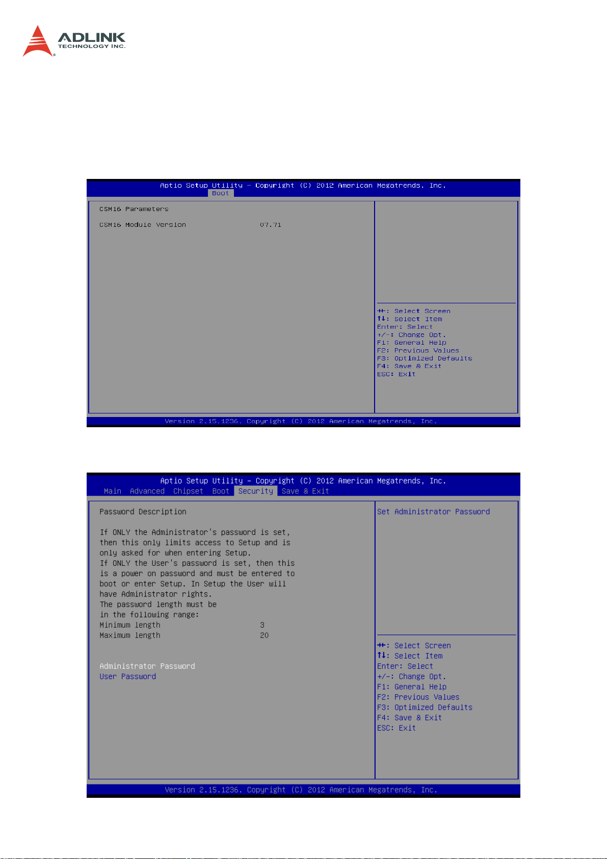
7.8 Security Setup
62
Page 63

CSA-5200
Administrator / User Password
If only the administrator’s password is set, then this limits access to setup and is only
asked for when entering setup.
If only the user’s password is set, then this is a power on password and must be
entered to boot or enter setup. In setup the user will have administrator rights.
7.9 Save & Exit Menu
Select the Exit tab from the setup screen to enter the Exit BIOS Setup screen. You can
display an Exit BIOS Setup option by highlighting it using the < Arrow > keys. The Exit BIOS
Setup screen is shown below.
Save Changes and Exit
Exit system setup after saving the changes.
63
Page 64

Discard Changes and Exit
Exit system setup without saving any changes.
Save Changes and Reset
Reset the system after saving the changes.
CSA-5200
Discard Changes and Reset
Reset system setup without saving any changes.
Save Changes
Save changes done so far to any of the setup options.
Discard Changes
Discard Changes done so far to any of the setup options.
64
Page 65

Restore Defaults
Restore/Load Defaults values for all the setup options.
Save as User Defaults
Save the changes done so far as user defaults.
CSA-5200
Restore User Defaults
Restore the user defaults to all the setup options.
65
Page 66

CSA-5200
Safety Instructions
For user safety, please read and follow all instructions, WARNINGS, CAUTIONS, and
NOTES marked in this manual and on the associated equipment before handling/operating
the equipment.
1. Read these safety instructions carefully.
2. Keep this user’s manual for future reference.
3. Read the specifications section of this manual for detailed information on the operating
environment of this equipment.
4. The equipment can be operated at an ambient temperature of 40°C.
5. When installing/mounting or uninstalling/removing equipment; or when removal of the
chassis lid required for user servicing (Section 3.1-3.5):
• Turn off power and unplug any power cords/cables, and
• Reinstall the chassis lid before restoring power.
6. To avoid electrical shock and/or damage to equipment:
• Keep equipment away from water or liquid sources;
• Keep equipment away from high heat or high humidity;
• Keep equipment properly ventilated (do not block or cover ventilation
openings);
• Make sure to use recommended voltage and power source settings;
• Always install and operate equipment near an easily accessible electrical socket-
outlet;
• Secure the power cord (do not place any object on/over the power cord);
• Only install/attach and operate equipment on stable surfaces and/or recommended
mountings;
• If the equipment will not be used for long periods of time, turn off and unplug the
equipment from its power source.
7. Never attempt to fix the equipment. Equipment should only be serviced by qualified
personnel.
8. A Lithium-type battery may be provided for uninterrupted, backup or emergency power.
CAUTION! Risk of explosion if battery is replaced with one of an incorrect type.
Please dispose of used batteries appropriately.
9. Equipment must be serviced by authorized technicians when:
• The power cord or plug is damaged;
• Liquid has penetrated the equipment;
• It has been exposed to high humidity/moisture;
• It is not functioning or does not function according to the user’s manual;
• It has been dropped and/or damaged; and/or,
• It has an obvious sign of breakage.
10. Please pay strict attention to all warnings and advisories appearing on the device, to
avoid injury or damage.
11. The equipment may have more than one power supply input. To reduce the risk of
electrical shock, trained personnel should disconnect all power supply inputs before
servicing.
CAUTION! Disconnect all power supply inputs before servicing.
66
Page 67

CSA-5200
Consignes de Sécurité Import antes
Pour assurer la sécurité de l’utilisateur, veuillez lire et suivre toutes les directives, ainsi que
les A VERTISSEMENTS, MISES EN GARDE et REMARQUES de ce manuel et indiqués sur
l’équipement associé avant de manipuler ou utiliser l’équipement.
1. Veuillez lire attentivement ces instructions de sécurité avec soin.
2. Veuillez conserver ce manuel pour référence future.
3. Veuillez lire la section des spécifications de ce manuel pour avoir des informations
détaillées sur l’environnement d’exploitation de cet équipement.
4. L’équipement peut être utilisé à une température ambiante de 40 °C.
5. Lors de l’installation ou du montage et de la désinstallation ou de la dépose de
l’équipement; ou lors de la dépose du couvercle du châssis pour procéder à l’entretien
par l’utilisateur (Sections 3.1-3.5):
• Coupez l’alimentation et débranchez les cordons et les câbles d’alimentation, et
• Reposez le couvercle du châssis avant de remettre l’alimentation.
6. Pour éviter un risque d’électrocution et pour éviter d’endommager l’équipement :
• Éloignez l’équipement de l’eau et de toute source liquide;
• Éloignez l’équipement de toute source de chaleur ou d’humidité élevée;
• Gardez l’équipement correctement ventilé (ne pas bloquer ou couvrir les ouvertures
de ventilation);
• Veillez à utiliser la tension recommandée et les réglages adéquats pour la source
d’alimentation;
• Veuillez toujours installer et exploiter l’équipement à proximité d’une prise de courant
facilement accessible;
• Assurez-vous que le cordon d’alimentation est acheminé de manière sécuritaire (ne
déposez aucun objet dessus);
• Installez, fixez et utilisez l’équipement sur des surfaces stables ou sur les fixations
recommandées uniquement;
• Si l’équipement n’est pas utilisé pendant une longue période, éteignez-le et
débranchez-le de sa source d’alimentation.
7. N’essayez jamais de réparer l’équipement. L’équipement ne doit être réparé que par du
personnel qualifié.
8. Une pile au lithium peut être installée pour assurer l’alimentation de secours ou
d’urgence en continu.
ATTENTION! Risque d’explosion si la pile est remplacée par une autre de type
incorrect. Veuillez jeter les piles usagées de façon appropriée.
9. L’équipement doit être entretenu par des techniciens agréés lorsque :
• le cordon d’alimentation est endommagé ou lorsque la fiche électrique est
endommagée;
• du liquide a pénétré à l’intérieur de l’équipement;
• l’équipement a été exposé à un taux d’humidité élevé;
• l’équipement ne fonctionne pas ou ne fonctionne pas conformément au manuel de
l’utilisateur;
• l’équipement est tombé ou lorsqu’il a été endommagé;
• l’équipement présente un signe évident de défaillance.
10. Veuillez porter une attention rigoureuse à tous les avertissements et à tous les avis
figurant sur l’appareil, pour éviter des blessures ou des dommages.
11. ATTENTION! L’équipement peut avoir plus d’une entrée d’alimentation. Pour réduire le
risque d’électrocution, le personnel qualifié devrait déconnecter toutes les entrées
d’alimentation avant de procéder à l’entretien.
67
Page 68

Getting Service
Contact us should you require any service or assistance.
ADLINK Technology, Inc.
Address: 9F, No.166 Jian Yi Road, Zhonghe District
New Taipei City 235, Taiwan
新北市中和區建一路 166 號 9 樓
Tel: +886-2-8226-5877
Fax: +886-2-8226-5717
Email: service@adlinktech.com
Ampro ADLINK Technology, Inc.
Address: 5215 Hellyer Avenue, #110, San Jose, CA 95138, USA
Tel: +1-408-360-0200
Toll Free: +1-800-966-5200 (USA only)
Fax: +1-408-360-0222
Email: info@adlinktech.com
ADLINK Technology (China) Co., Ltd.
Address: 上海市浦东新区张江高科技园区芳春路 300 号 (201203)
300 Fang Chun Rd., Zhangjiang Hi-Tech Park, Pudong New Area
Shanghai, 201203 China
Tel: +86-21-5132-8988
Fax: +86-21-5132-3588
Email: market@adlinktech.com
ADLINK Technology Beijing
Address: 北京市海淀区上地东路 1 号盈创动力大厦 E 座 801 室(100085)
Rm. 801, Power Creative E, No. 1, B/D, Shang Di East Rd.
Beijing, 100085 China
Tel: +86-10-5885-8666
Fax: +86-10-5885-8625
Email: market@adlinktech.com
ADLINK Technology Shenzhen
Address: 深圳市南山区科技园南区高新南七道 数字技术园 A1 栋 2 楼 C 区 (518057)
2F, C Block, Bldg. A1, Cyber-Tech Zone, Gao Xin Ave. Sec. 7
High-Tech Industrial Park S., Shenzhen, 518054 China
Tel: +86-755-2643-4858
Fax: +86-755-2664-6353
Email: market@adlinktech.com
LiPPERT ADLINK Technology GmbH
Address: Hans-Thoma-Strasse 11, D-68163, Mannheim, Germany
Tel: +49-621-43214-0
Fax: +49-621 43214-30
Email: emea@adlinktech.com
CSA-5200
68
Page 69

CSA-5200
ADLINK Technology, Inc. (French Liaison Office)
Address: 6 allée de Londres, Immeuble Ceylan
91940 Les Ulis, France
Tel: +33 (0) 1 60 12 35 66
Fax: +33 (0) 1 60 12 35 66
Email: france@adlinktech.com
ADLINK Technology Japan Corporation
Address: 〒101-0045 東京都千代田区神田鍛冶町 3-7-4
神田 374 ビル 4F
KANDA374 Bldg. 4F, 3-7-4 Kanda Kajicho,
Chiyoda-ku, Tokyo 101-0045, Japan
Tel: +81-3-4455-3722
Fax: +81-3-5209-6013
Email: japan@adlinktech.com
ADLINK Technology, Inc. (Korean Liaison Office)
Address: 137-881 서울시 서초구 서초대로 326, 802 (서초동, 모인터빌딩)
802, Mointer B/D, 326 Seocho-daero, Seocho-Gu,
Seoul 137-881, Korea
Tel: +82-2-2057-0565
Fax: +82-2-2057-0563
Email: korea@adlinktech.com
ADLINK Technology Singapore Pte. Ltd.
Address: 84 Genting Lane #07-02A, Cityneon Design Centre,
Singapore 349584
Tel: +65-6844-2261
Fax: +65-6844-2263
Email: singapore@adlinktech.com
ADLINK Technology Singapore Pte. Ltd. (Indian Liaison Office)
Address: #50-56, First Floor, Spearhead Towers
Margosa Main Road (between 16th/17th Cross)
Malleswaram, Bangalore - 560 055, India
Tel: +91-80-65605817, +91-80-42246107
Fax: +91-80-23464606
Email: india@adlinktech.com
ADLINK Technology, Inc. (Israeli Liaison Office)
Address: 27 Maskit St., Corex Building
PO Box 12777
Herzliya 4673300, Israel
Tel: +972-54-632-5251
Fax: +972-77-208-0230
Email: israel@adlinktech.com
ADLINK Technology, Inc. (UK Liaison Office)
Tel: +44 774 010 59 65
Email: UK@adlinktech.com
69
 Loading...