

CSA-5100
1U Rackmount Network Appliance
with Intel® Xeon® Processor E3-1200 v3 Family
User’s Manual
Manual Revision: 1.01
Revision Date: November 25, 2014
Part No.: 50-1Z176-1000
Advance Technologies; Automate the World.

CSA-5100
Revision History
Revision Release Date Description of Change(s)
1.00 18/08/2014 Initial release
1.01 25/11/2014 Remove CSA-5200; add French safety chapter;
update fans, CPU heatsink
Copyright 2014 ADLINK Technology, Inc.
All Rights Reserved.
The information in this document is subject to change without prior notice in order to improve
reliability, design, and function and does not represent a commitment on the part of the
manufacturer.
In no event will the manufacturer be liable for direct, indirect, special, incidental, or
consequential damages arising out of the use or inability to use the product or
documentation, even if advised of the possibility of such damages.
This document contains proprietary information protected by copyright. All rights are
reserved. No part of this manual may be reproduced by any mechanical, electronic, or other
means in any form without prior written permission of the manufacturer.
Trademarks
Product names mentioned herein are used for identification purposes only and may be
trademarks and/or registered trademarks of their respective companies.
2

CSA-5100
Table of Contents
Revision History................................................................................................................... 2
1 Overview .......................................................................................................................... 5
1.1 Introduction .............................................................................................................................. 5
1.2 Block Diagram.......................................................................................................................... 6
1.3 Mechanical Overview............................................................................................................... 7
1.3.1 Front Panel ........................................................................................................................................7
1.3.2 Rear Panel.........................................................................................................................................7
1.3.3 Chassis Layout ..................................................................................................................................8
1.4 Mechanical Dimensions ........................................................................................................... 9
1.4.1 Dimensions........................................................................................................................................9
1.5 Package Contents.................................................................................................................. 10
2 Specifications.................................................................................................................11
2.1 CSA-5100 Specifications ........................................................................................................11
2.2 Software Support ................................................................................................................... 12
2.3 Network Mezzanine Card Support ......................................................................................... 12
2.4 Optional Accessories ............................................................................................................. 12
3 Getting Started............................................................................................................... 13
3.1 Removing the Chassis Lid ..................................................................................................... 13
3.2 Installing the CPU/Heatsink ................................................................................................... 13
3.3 Installing a 2.5" SATA Drive.................................................................................................... 16
3.4 Installing a Network Interface Module.................................................................................... 19
3.5 Driver Installation ................................................................................................................... 21
4 System Interfaces.......................................................................................................... 22
4.1 Front Panel I/O....................................................................................................................... 22
4.1.1 Status LEDs.....................................................................................................................................22
4.1.2 LAN Connector (RJ-45) ...................................................................................................................22
4.1.3 Service Port Status LEDs ................................................................................................................23
4.1.4 USB 3.0 Connectors........................................................................................................................23
4.1.5 Remote Console Connector (RJ-45) ...............................................................................................23
4.2 Board Layout.......................................................................................................................... 24
4.3 Connectors and Jumpers....................................................................................................... 25
4.3.1 PCIe x4 Connector (PCIE1) ............................................................................................................25
4.3.2 CFast Connector (CN17).................................................................................................................26
4.3.3 VGA Header (CNX1) .......................................................................................................................26
4.3.4 ATX12V Connector (CN24) .............................................................................................................27
4.3.5 Fan Connectors (FAN1/FAN6-9) .....................................................................................................27
4.3.6 ATX Connector (CN19)....................................................................................................................27
4.3.7 mSATA Connectors (CN9/CN48).....................................................................................................28
4.3.8 SATA Connectors (CN30-33)...........................................................................................................28
4.3.9 SATADOM Power Connector (CN18, Wafer 1.25mm pitch)............................................................29
4.3.10 Clear CMOS Jumper (JBAT1) .......................................................................................................29
4.3.11 NIM Slot connectors (PCI1-4)........................................................................................................29
5 LAN Bypass Function................................................................................................... 31
5.1 Hardware Description ............................................................................................................ 31
5.2 BIOS Settings ........................................................................................................................ 32
5.3 SuperIO Watchdog Driver & API ............................................................................................ 33
5.3.1 Overview..........................................................................................................................................33
3

CSA-5100
6 Watchdog Timer Programming .................................................................................... 35
6.1 Architecture Overview............................................................................................................ 35
6.2 Deliverables ........................................................................................................................... 36
6.2.1 open.................................................................................................................................................36
6.2.2 write .................................................................................................................................................36
6.2.3 ioctl ..................................................................................................................................................37
6.2.4 release .............................................................................................................................................38
6.3 Sample Code ......................................................................................................................... 38
7 BIOS Setup..................................................................................................................... 41
7.1 Entering BIOS Setup.............................................................................................................. 41
7.2 Setup Menu............................................................................................................................ 42
7.3 Navigation .............................................................................................................................. 42
7.4 Main Setup............................................................................................................................. 45
7.4.1 System & Board Info........................................................................................................................45
7.4.2 System Date/System Time ..............................................................................................................46
7.5 Advanced BIOS Setup ........................................................................................................... 46
7.5.1 ACPI Settings ..................................................................................................................................47
7.5.2 CPU Configuration...........................................................................................................................47
7.5.3 SATA Configuration..........................................................................................................................49
7.5.4 PCH-FW Configuration....................................................................................................................50
7.5.5 USB Configuration...........................................................................................................................50
7.5.6 Super IO Configuration....................................................................................................................51
7.5.7 IT8786 HW Monitor .........................................................................................................................52
7.5.8 Smart Fan Function .........................................................................................................................53
7.5.9 Serial Port Console Redirection ......................................................................................................54
7.6 Chipset Setup ........................................................................................................................ 57
7.6.1 PCH-IO Configuration......................................................................................................................57
7.6.2 System Agent (SA) Configuration....................................................................................................59
7.7 Boot Setup ............................................................................................................................. 62
7.8 Security Setup........................................................................................................................ 63
7.9 Save & Exit Menu .................................................................................................................. 64
Safety Instructions............................................................................................................. 67
Consignes de Sécurité Importantes ................................................................................. 68
Getting Service................................................................................................................... 69
4

CSA-5100
1 Overview
1.1 Introduction
The ADLINK CSA-5100 is a 1U 19" rackmount Network Appliance with 4th Generation Intel®
processor Xeon® E3-1200 v3 and Intel® C226 Chipset. The CSA-5100 features up to 32x
GbE ports or 8x SFP+ with an I/O intensive architecture, high scalability with four Network
Interface Module (NIM) slots, 2.5’’ SATA drive bay, 2 mSATA slots, additional storage
interfaces (SATADOM, CFast), and is an ideal platform for communications infrastructure
deployment.
Detailed features are outlined below and a functional block diagram is shown in the next
section.
4th Gen Intel® processor Xeon® E3-1200 v3 with Intel® C226 Chipset
• Intel® Xeon® E3-1275 v3 (4C/8T)
• Intel® Xeon® E3-1225 v3 (4C/4T)
• Intel® Core™ i3-4330 (2C/4T)
8MB/4M/3M/2M L2 cache, depending on CPU
4x DDR3-1066/1333/1600 240-pin DIMM sockets, non-ECC, up to 32 GB
Up to 32x GbE ports or 8x SFP+ with I/O intensive architecture
High scalability with four Network Interface Module (NIM) slots
One 2.5’’ SATA drive bay, two mSATA slots
Additional storage interfaces: SATADOM, CFast
1U 19’’ rackmount form factor for communications infrastructure deployment
5
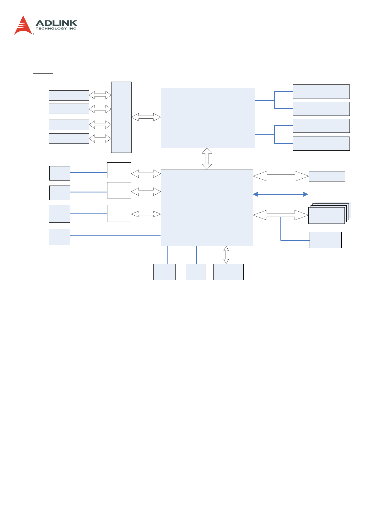
1.2 Block Diagram
CSA-5100
UDIMM
DDR3 1600MHz
UDIMM
DDR3
1600MHz
UDIMM
1600MHz
DDR3
UDIMM
1600MHz
DDR3
BIOS
to NIM slots
2.5" SATA
2x mSATA
SATADOM
F
R
O
N
T
P
A
N
E
L
NIM slot
(PCIe x8, GPIO)
NIM slot
(PCIe x8, GPIO)
NIM slot
(PCIe x8, GPIO)
NIM slot
(PCIe x8, GPIO)
RJ-45
GbE
RJ-45
GbE
RJ-45
COM
USB 3.0
x2
1000M MDI+/-
1000M MDI+/-
PCIe Switch
Intel
I211AT
Intel
I211AT
Super
IO
PCIe 3.0 x16
PCIe x1
PCIe x1
LPC
VGA
VGA
header
Intel®Xeon®
E3-1200 v3
DMI 2.0 x4
Intel PCH
C226
SATA
CFast
socket
PCIe x4
socket
SPI
GPIO
SATA x4
PCIe 2.0 x4
6
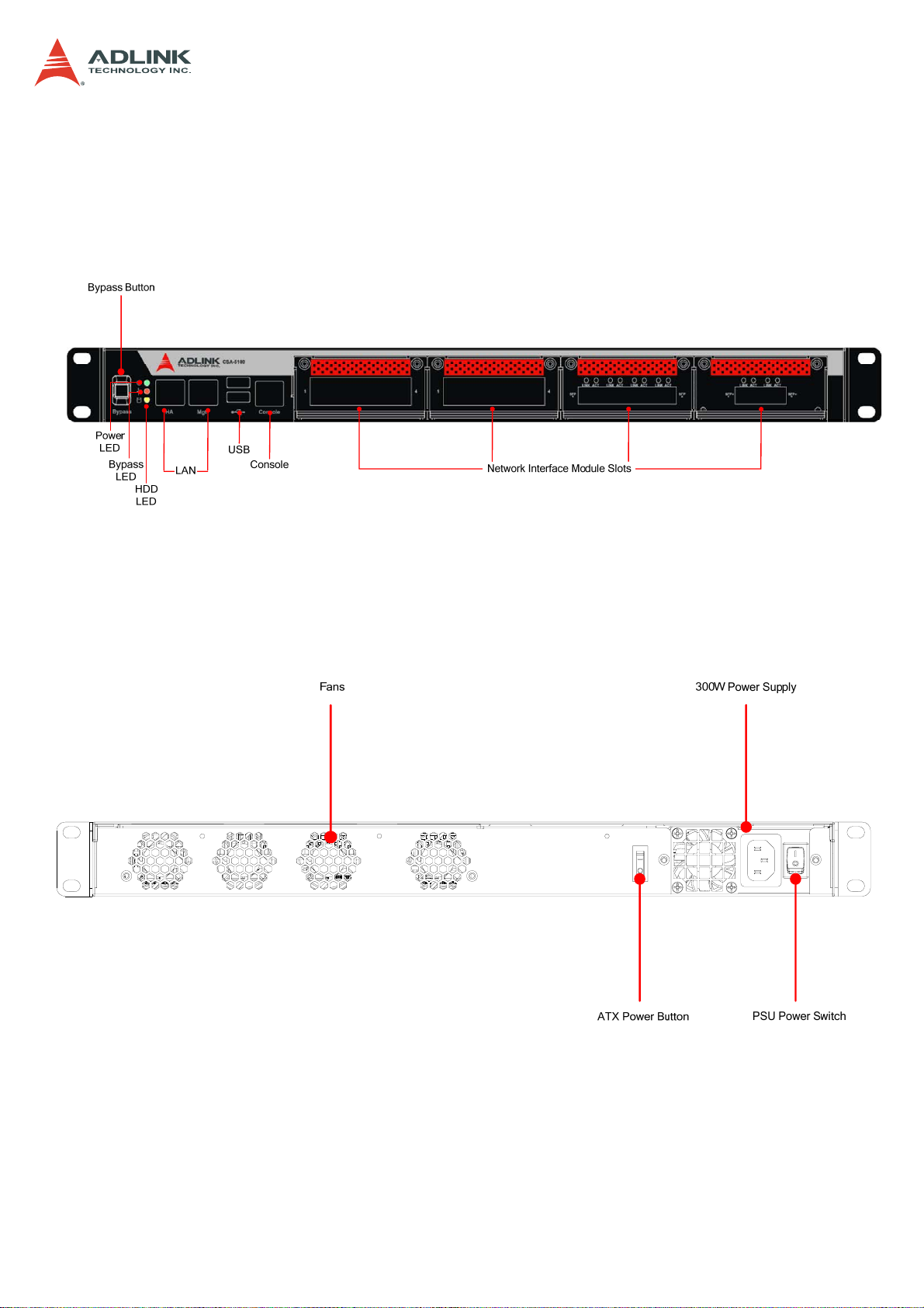
1.3 Mechanical Overview
1.3.1 Front Panel
CSA-5100
1.3.2 Rear Panel
7
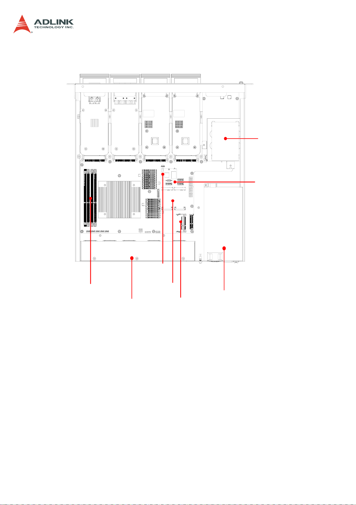
1.3.3 Chassis Layout
CSA-5100
SATA
Drive Bay
DDR3 DIMMs x4
SATADOM
Power
Fans
mSATA
CFast
Power Supply
SATA
Connectors
8
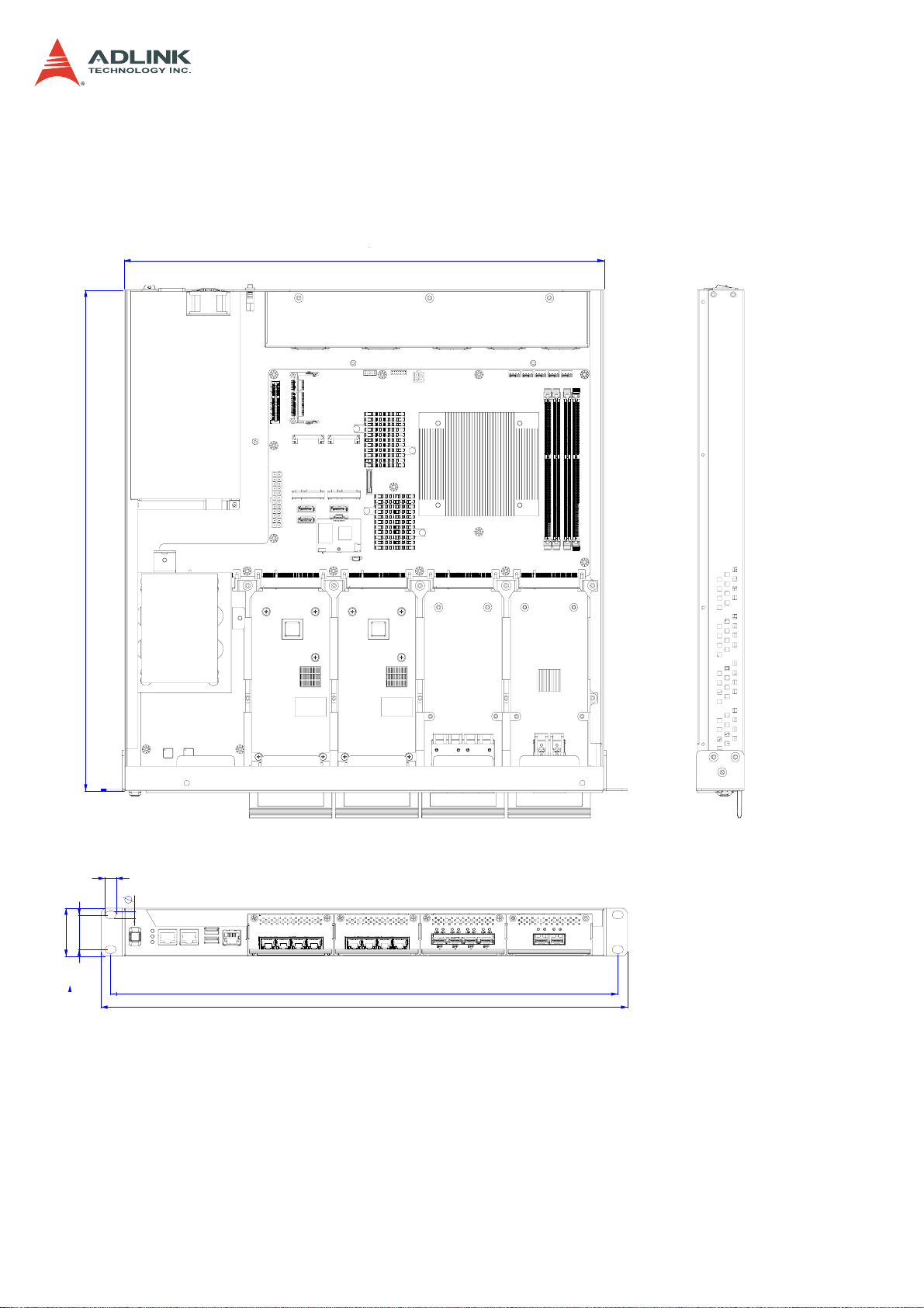
1.4 Mechanical Dimensions
1.4.1 Dimensions
440
CSA-5100
458.80
10.30
7
44
31.75
Dimensions in mm
465
482.60
9

CSA-5100
1.5 Package Contents
Before opening, please check the shipping carton for any damage. If the shipping carton and
contents are damaged, notify the dealer for a replacement. Retain the shipping carton and
packing material for inspection by the dealer. Obtain authorization before returning any
product to ADLINK.
Check that the following items are included in the package. If there are any missing items,
contact your dealer:
CSA-5100 Rackmount Network Appliance
VGA cable (pin header to DB-15)
Remote console cable (RJ-45 to DB-9)
Accessory pack (drive bracket mounting hardware)
Power cord
ADLINK All-In-One CD
10
2 Specifications
2.1 CSA-5100 Specifications
Main System
CPU
Intel® Xeon® E3-1275 v3 (4C/8T)
Intel® Xeon® E3-1225 v3 (4C/4T)
Intel® Core™ i3-4330 (2C/4T)
CSA-5100
L2 Cache
Chipset
Memory
BIOS
Operating Systems
Power Supply
8MB/8MB/4MB
Intel® C226 PCH
Four DDR3-1066/1333/1600 * 240-Pin Long-DIMM sockets, nonECC, up to 32 GB
AMI BIOS on SPI flash memory
Windows 7 64bit, Linux kernel 2.6 and above
(default: no OS installed)
1U: 300W AC
I/O Interfaces - Front
NIM Slots
Ethernet
Remote Console
USB
4x Network Interface Module (NIM) slots
2x RJ-45 10/100/1000BASE-T Ethernet port
1x RJ-45 serial port
2x USB 3.0
I/O Interfaces - Onboard
Security Acceleration
Graphics
1x PCIe x4 Gen2 socket for acceleration card
1x VGA header onboard
Storage
Drive Bays
1x 2.5” SATA drive bay, 2x mSATA
Other
Buttons/LEDs
Power
Bypass
LEDs
1x SATADOM, 1x CFast socket
1x ATX power button, rocker type (rear)
1x bypass button (front)
Power, Bypass Status, Drive Activity
11
Mechanical & Environmental
Form Factor
19” 1U rackmount 440mm x 44mm x 440 mm (W x H x D)
CSA-5100
Fans
Power
Temperature
Humidity
Shock
Vibration
Acoustic Level
Certifications
MTBF
4x fans speed adjustable
Able to operate with 1 fan out of service
300W, 100V-240VAC @ 60-50 Hz, full range, non-redundant
power supply
Operating temp.: 0°C -40°C
Storage temp.: -40°C to 70°C
Short term operating: -5°C to +45°C (5%-90% rel. humidity)
Operating: 20% - 90% @40°C, non-condensing
Storage: 5% - 90%, non-condensing
Operating: half-sine 2G, 11ms pulse, 100 pulses in each direction,
on each of three axes
Non-operating: trapezoidal, 25G, 170 inches/sec delta V, three
drops in each direction, on each of three axes
Non-operating: 2.2Grms, 10 minutes per axis on all three axes
Sound pressure < 75 dBA @1m with all fans at maximum speed
FCC Class A, CE emissions, UL, CB and RoHS compliant
50,000 hours
2.2 Software Support
ADLINK DPDK
Toolkit
ADLINK DPI Toolkit
ADLINK Load
Balancing Toolkit
Enables Intel® DPDK
Intel® DPDK-based openDPI to boost DPI performance
Intel® DPDK vSwitch-based Load Balancer
2.3 Network Mezzanine Card Support
CSA-Z4X01
CSA-Z5C4F
CSA-Z8X10
CSA-Z5C2F
4-port GbE copper with LAN bypass PN: 91-37584-100E
4-port GbE SFP without LAN bypass PN: 91-37585-000E
8-port GbE copper with LAN bypass PN: 91-37588-000E
2-port SFP+ without LAN bypass PN: 91-37589-000E
2.4 Optional Accessories
Riser Card
Riser card for PCIe x4 acceleration card PN: 91-37591-000E
12
3 Getting Started
3.1 Removing the Chassis Lid
1. Remove the four screws securing each side of the lid to the chassis.
2. Remove the three screws securing the rear of the lid to the chassis.
3. Slide the lid to the rear and remove from the chassis.
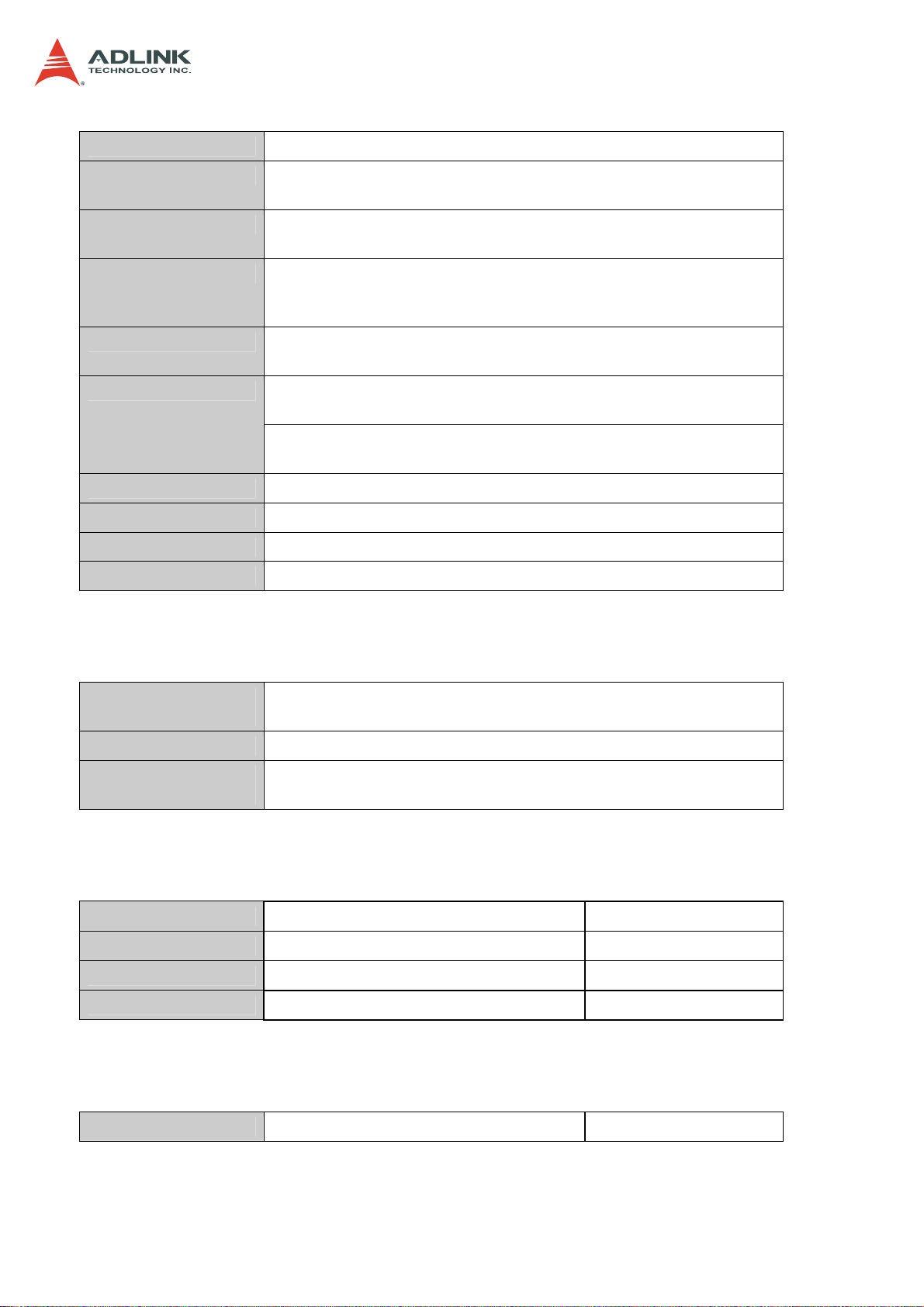
3.2 Installing the CPU/Heatsink
1. Locate the CPU sockets on the board.
2. Press the load lever, move it outwards until it is clear of the retention tab, then raise it
CSA-5100
3. Open the load plate and remove the protective cover from the socket. Do not touch
the socket contacts or the bottom of the processor.
13
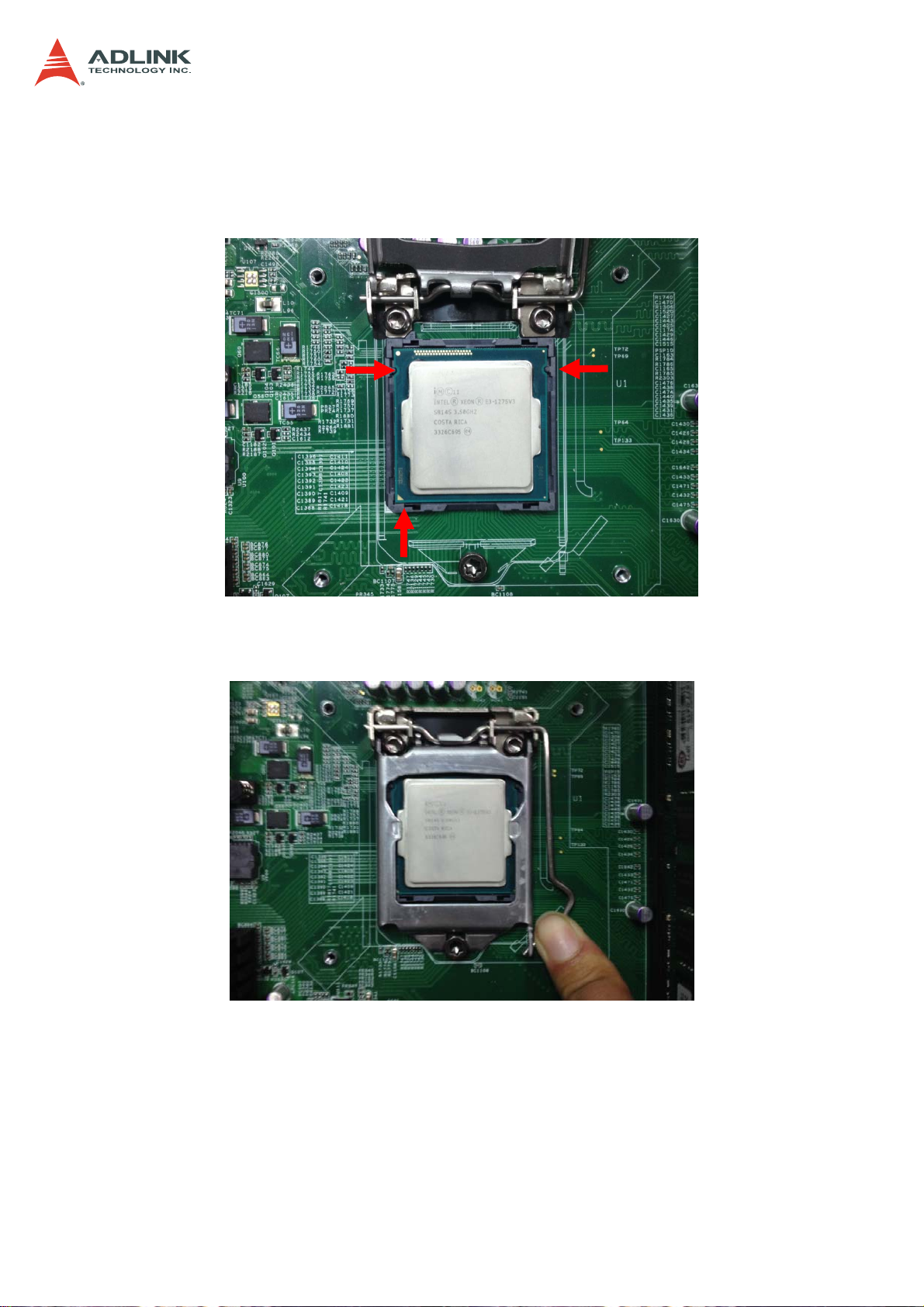
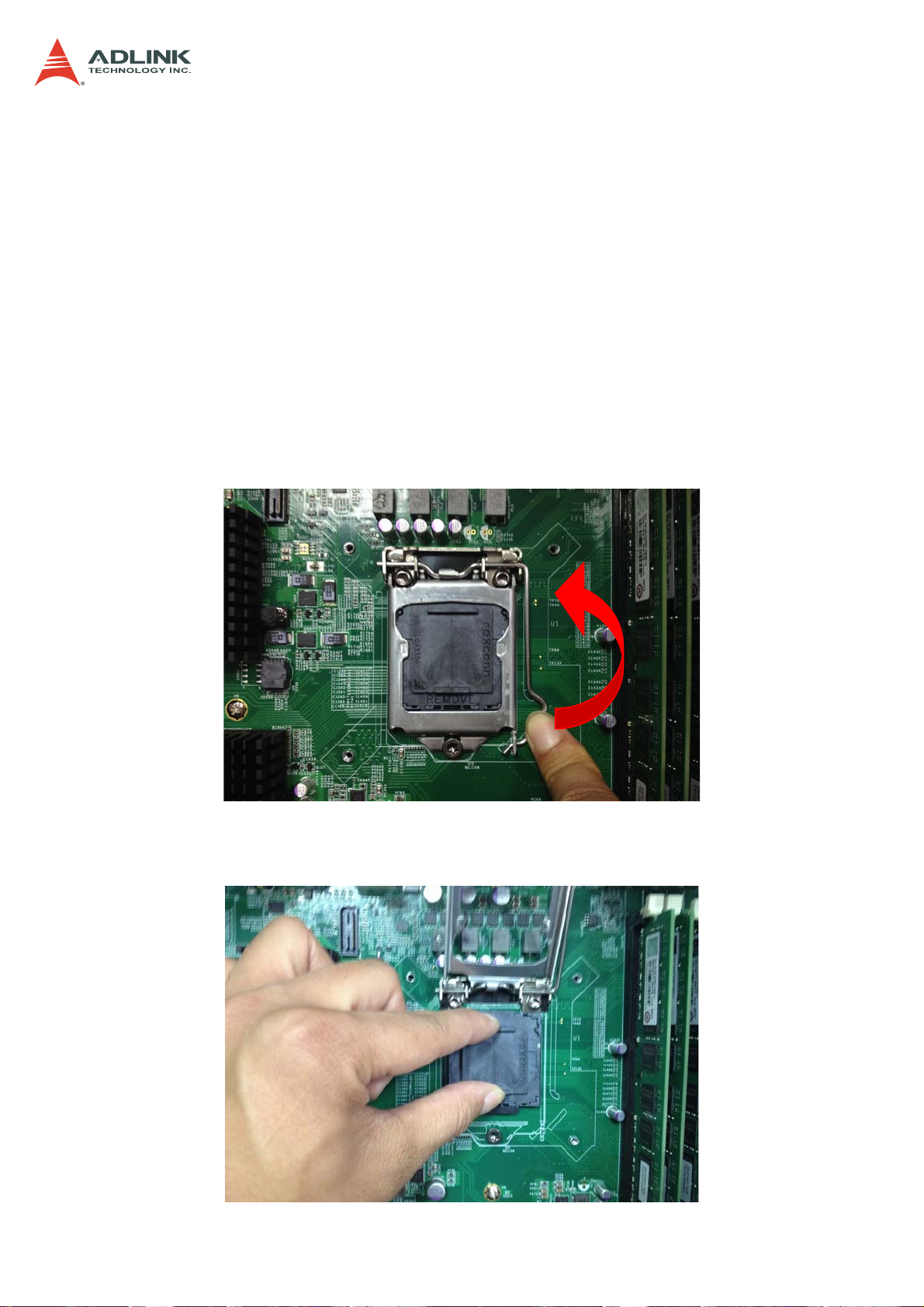
4. Carefully place the CPU into the socket, making sure the socket notches align with
the processor notches and the alignment triangle on the CPU lines up with the correct
corner on the socket,. Lower the processor straight down, without tilting or sliding the
processor in the socket. Gently release the processor, making sure that it is seated
correctly in the socket.
CSA-5100
5. Close the load plate, push the load lever back down, and engage it with the retention
tab.
14
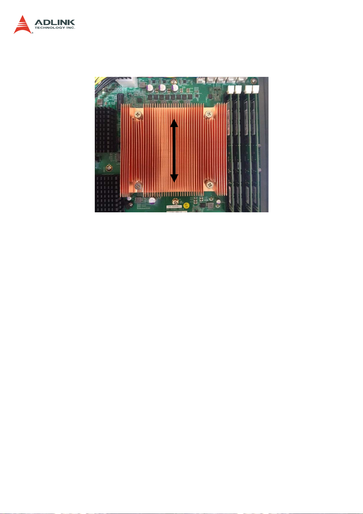
6. Make sure there is sufficient thermal paste on of the heatsink and place it on the CPU
with the cooling fins aligned with the DIMM slots as shown.
CSA-5100
7. Tighten the captive screws in an "X" pattern until the heatsink is secured on the CPU.
Do NOT over tighten the screws
15
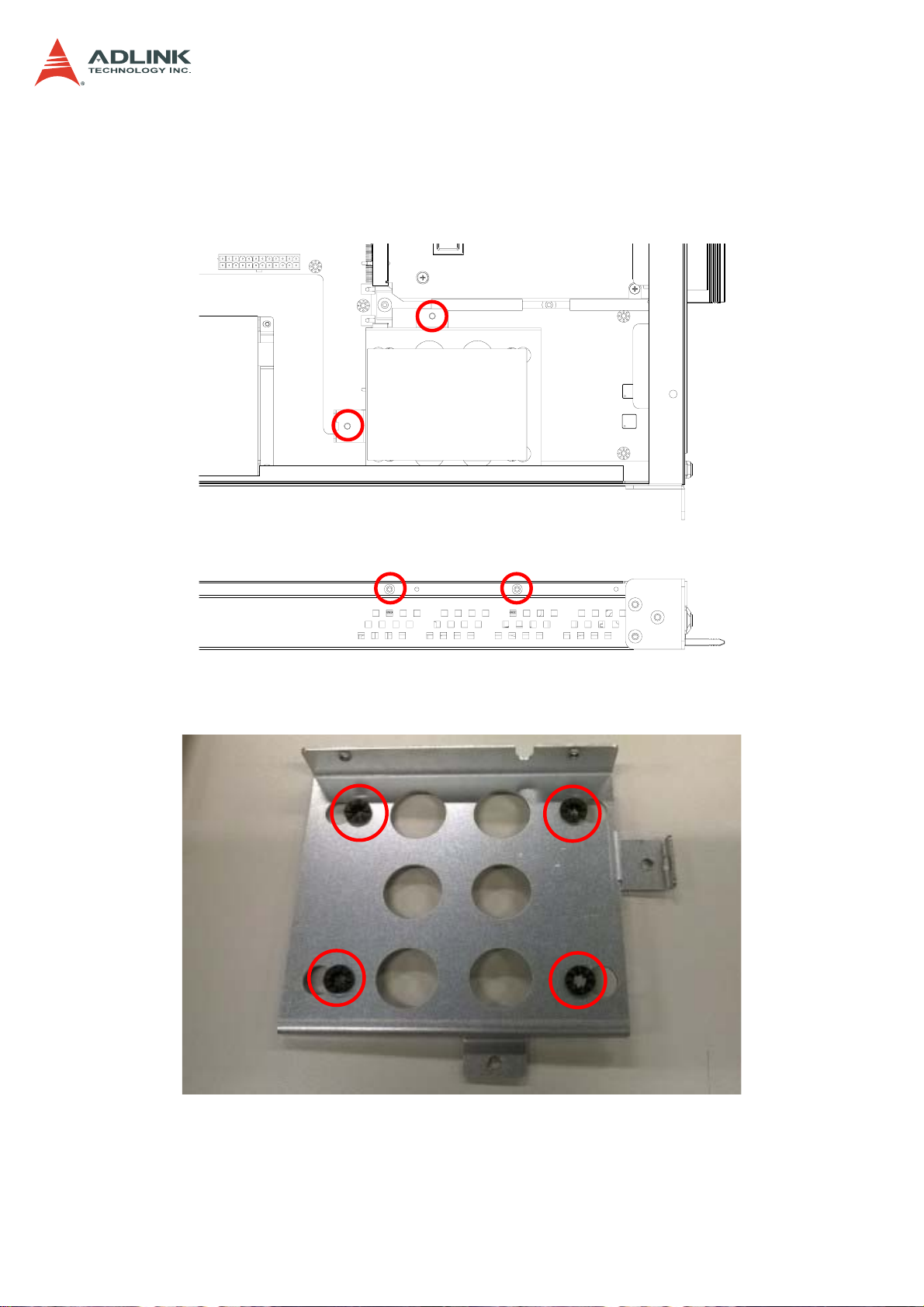
3.3 Installing a 2.5" SATA Drive
1. Loosen the 4 screws securing the drive bracket to the chassis shown below and lift
the bracket out.
CSA-5100
2. Insert the anti-shock grommets provided in the accessory pack as shown.
16
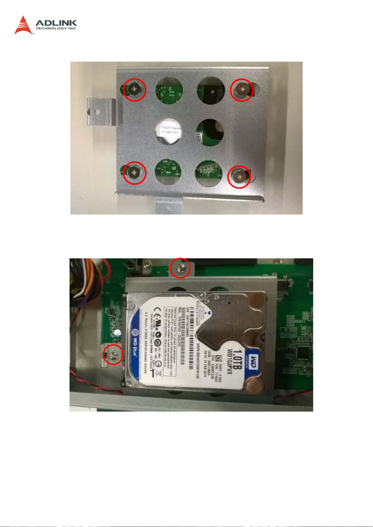
3. Secure the 2.5" SATA drive to the bracket with four screws.
CSA-5100
4. Install the drive/bracket assembly to the chassis, making sure to align the screw holes
with the standoffs as shown. Secure the two screws.
17
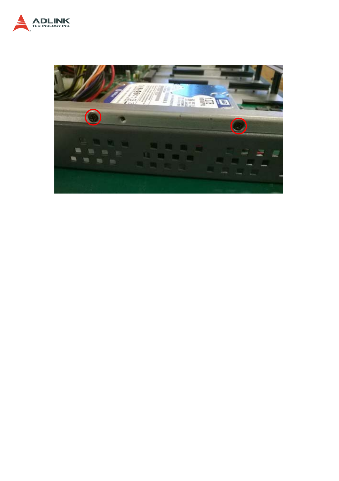
5. Secure the two screws on the side of the chassis as shown below.
CSA-5100
18

3.4 Installing a Network Interface Module
1. Loosen the two screws on the Network Interface Module (NIM) faceplate, and pull
outwards on the handle to remove the faceplate.
CSA-5100
2. Align the NIM with the card guides in the slot as shown below.
19
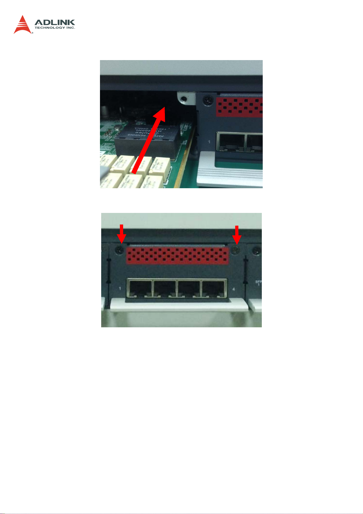
3. Insert the NIM into the slot.
4. Secure the NIM with the two screws removed in Step 1.
CSA-5100
20

CSA-5100
3.5 Driver Installation
The CSA-5100 drivers are available from the ADLINK All-In-One DVD at X:\CSA-5200\, or
from the ADLINK website at: http://www.adlinktech.com/PD/web/PD_detail.php?
pid=1429.
ADLINK provides validated drivers for Windows 7 64-bit. We recommend using these drivers
to ensure compatibility.
The following describes the CSA-5100 driver installation procedures for Windows 7. Install
the Windows operating system before installing any driver. Most standard I/O device drivers
are installed during Windows installation.
1. Install the chipset driver by extracting and running the program in ...
\Driver_Infinst_autol\ infinst_autol.zip
2. Install the graphics driver and utilities by extracting and running the program in ...
\Graphics_Driver_WIN7_64bit\ graphic_win64_10.18.10.3496.zip.
3. Install the LAN driver by running the program in …\LAN_Win7\PROWinx64.zip.
4. Install the Intel Management Engine and utilities by extracting and running the
program in …\Intel_ME9.1_5M\ Intel_ME9.1_5M_9.1.0.1035.zip.
5. Install the Intel Rapid Storage Technology utility by extracting and running the
program in …\Intel Rapid Storage Technology\irst_12.5.0.1040.zip.
6. Install the USB 3.0 driver by running the program in …
\USB_3.0_Win7\ USB_3.0_Win7_2.5.1.28.zip.
21
 Loading...