

Page 1

cPCIS-ET2600 Series
4U Height Wide Temperature Range
Subsystem for 3U CompactPCI Modules
User’s Guide
Page 2

Copyright 2013 ADLINK Technology, Inc.
All Rights Reserved.
Manual Rev. 1.00, January 2, 2013
Part No.: 50-15088-2000
The information in this document is subject to change without prior notice in
order to improve reliability, design and function and does not represent a
commitment on the part of the manufacturer.
In no event will the manufacturer be liable for direct, indirect, special, incidental,
or consequential damages arising out of the use or inability to use the product
or documentation, even if advised of the possibility of such damages.
This document contains proprietary information protected by copyright. All
rights are reserved. No part of this manual may be reproduced by any
mechanical, electronic, or other means in any form without prior written
permission of the manufacturer.
Trademarks
Product names mentioned herein are used for identification purposes only and
may be trademarks and/or registered trademarks of their respective companies.
Page 3

Table of Contents
How to Use This Manual................................................................v
1 Introduction ....................................................................................1
1.1 Product Definition ......................................................................1
1.2 Mechanical Drawing ..................................................................2
1.3 Configurations............................................................................3
1.4 Customized Systems.................................................................3
2 Getting Started ...............................................................................5
2.1 Shipping Contents .....................................................................5
2.2 CompactPCI Board & PSU Installation cPCIS-ET2600 Series
models with CompactPCI PSU(s) .......................................................
2.3 RTM (Rear Transition Module) Installation................................9
2.4 Powering Up the System...........................................................9
3 Backplane .....................................................................................10
3.1 cBP-3208[R] Backplane...........................................................10
Specifications .....................................................................10
Mechanical Drawing...........................................................11
Pin Assignment...................................................................13
3.2 cBP-3206[R] Backplane...........................................................17
Specifications .....................................................................17
Mechanical Drawing...........................................................18
Pin Assignment...................................................................19
3.3 cBP-3061 Power Backplane....................................................23
Specifications .....................................................................23
Mechanical Drawing...........................................................23
Pin Assignment...................................................................24
3.4 cBP-3062 Power Backplane....................................................27
Specifications .....................................................................27
Mechanical Drawing...........................................................27
Pin Assignment...................................................................28
5
4 Cooling System............................................................................31
4.1 Removing and Replacing the Air Filters cPCIS-ET2600 Series
models with CompactPCI PSU(s) .....................................................
4.2 Fan Alarm: Fan Removal and Replacement...........................33
Table of Contents • iii
31
Page 4

4.3 Temperature Alarm..................................................................34
4.4 Fan Specifications ...................................................................34
Mechanical Drawing...........................................................34
5 Power Supply Unit .......................................................................35
5.1 CompactPCI: cPS-P325/AC....................................................35
Features .............................................................................35
Specifications .....................................................................35
Input Characteristics...........................................................36
Output Characteristics........................................................36
6 Specifications...............................................................................39
6.1 Features...................................................................................39
6.2 Mechanical...............................................................................39
6.3 Environmental..........................................................................40
6.4 System Alarm Board................................................................40
Important Safety Instructions ...................................................43
Getting Service...............................................................................45
iv • Table of Contents
Page 5

How to Use This Manual
This manual is designed to help you use the cPCIS-ET2600 series 3U
CompactPCI Subsystem . It is divided into six chapters:
Chapter 1: Introduction
Chapter 2: Getting Started,
and configuration of the subsystem .
Chapter 3: Backplane
used in the cPCIS-ET2600 Series subsystems.
Chapter 4: Cooling System
subsystem air filters, fan and temperature alarm conditions
and the hot swappable fans used to cool the subsystem .
Chapter 5: Power Supply Unit
ET2600 Series subsystems.
Chapter 6: Specifications
specifications.
, gives an overview of the product features.
describes the unpacking procedure, setup
, gives a detailed description of the backplanes
, describes how to remove and replace the
, describes the PSUs of the cPCIS-
, describes the subsystem's detailed
How to Use This Manual • v
Page 6

This page intentionally left blank.
vi • Introduction
Page 7
1 Introduction
1.1 Product Definition
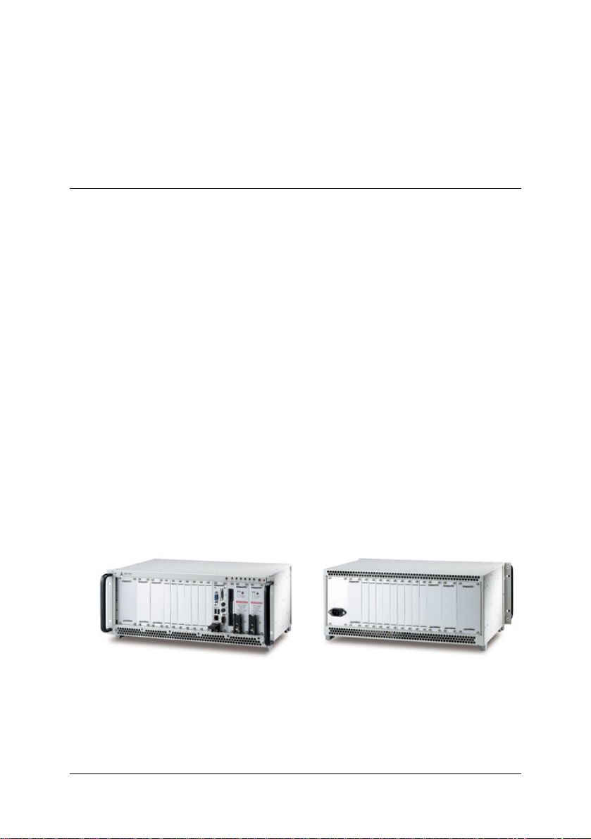
The cPCIS-ET2600 wide temperature range subsystem is rack mountable,
4U in height, and designed for 3U CompactPCI cards and modules. They ar e
ideal for industrial or transport applications where small chassis size with
multi-functionality are important, and provide maximum cooling efficienc y, a
guarded power on/off button, ample power capacity, a hot swap backplane
and easy maintenance. Their ability to handle a wide range of temperatu res
and excellent shock and vibration characteristics make them suitable for
operating in a rigorous environment. An embedded alarm board monitors
temperature & fan status to maximize continuous operation. The cPCISET2600 Series allows for custom configuration, giving system integrators
maximum flexibility to build in specialized functionality.
This user’s manual provides unpacking, operating, and maintenance
information for the cPCIS-ET2600 3U CompactPCI subsystem. The cPCISET2600 subsystem is assembled using the following components:
Components:
• Chassis: cPRK-2600ET
• Power Supply: 3U CompactPCI
• Backplane: PICMG 2.0 R3.0 Hot Swap compatibility
• Cooling: 5 hot swappable, push-in fans with removable air filters
cPCIS-ET2632R shown
Introduction • 1
Page 8
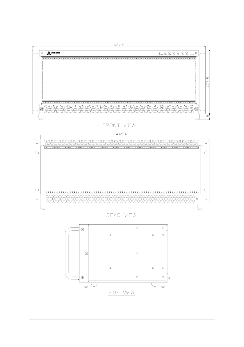
1.2 Mechanical Drawing
R
2 • Introduction
Page 9

1.3 Configurations
The cPCI-ET2600 Series comes in the following configuration:
cPCIS-
ET2632[R]
*cPCIS-ET2632 is available with rear I/O backplanes for Rear Transition
Modules (RTMs) and is indicated by an “R” suffix on the model name .
system
slots
peripheral
slots
1 7
250W cPCI
PSU(s) monitor PICMG
(1 + 1)
— 2.0, 2.1, 2.11
1.4 Customized Systems
Subsystem s can also be customized to meet individual nee ds. To customize
a subsystem please contact an ADLINK dealer. For complete systems, users
must order CPU modules in addition to the subsystem .
Introduction • 3
Page 10

This page intentionally left blank.
4 • Introduction
Page 11

2 Getting Started
In this chapter, we will describe the unpacking procedure of the subsystem
and CompactPCI board and power supply unit (PSU) installation procedures
for cPCIS-ET2600 Series models with CompactPCI PSU(s) only.
2.1 Shipping Contents
Check the shipping carton for any damage. If the shipping carton and
contents are damaged, please notify the dealer for a replacement. Ret ain
the shipping carton and packing material for inspection by the deal er. Obtain
authorization before returning any product to ADLINK.
Check that the following items are included in the package. If there are any
missing items, please contact your dealer:
• One cPCIS-ET2600 Series subsystem
• This User’s Manual
• Power cord (either N. American or European)
2.2 CompactPCI Board & PSU Installation
cPCIS-ET2600 Series models with CompactPCI PSU(s)
The CompactPCI connectors are rigid and require careful handling when
inserted and removed. Improper handling of cards can easily damage the
backplane.
The PSU slot also has an obvious indicator such as a green card guide rail in a
standard CompactPCI chassis (see photo below).
Backplane • 5
Page 12
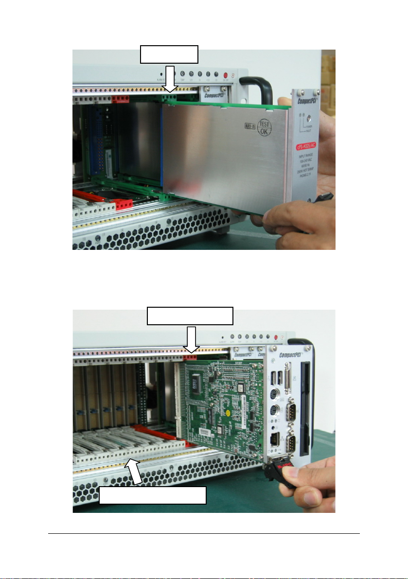
PSU Slot
System slots usually have obvious indicators (e.g. red card guide rail, triangle
mark enclosing the slot number on the backplane, etc.) System cards can only
be installed in a system slot. Do not insert a system card into any other slot, or
insert any peripheral card into system slot.
System Card Slot
Peripheral Card Slots
6 • Backplane
Page 13
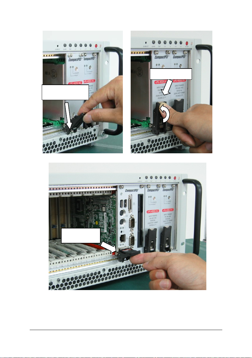
The handle on CompactPCI cards and PSUs ensures simple and safe
installation and removal. Please follow the procedures below to install a
CompactPCI module into a cPCIS-ET2600 Series chassis with CompactPCI
PSU(s):
CompactPCI Card Installation/Removal Procedure
1. Place the subsystem on a level surface or rackmount it. Remove the
blanking plates where required by undoing the retaining screws at each
end. Retain the blanking plates for possible future use. The system should
not be put into use without blanking plates for all empty slots, otherwise the
EMC and cooling performance will be compromised
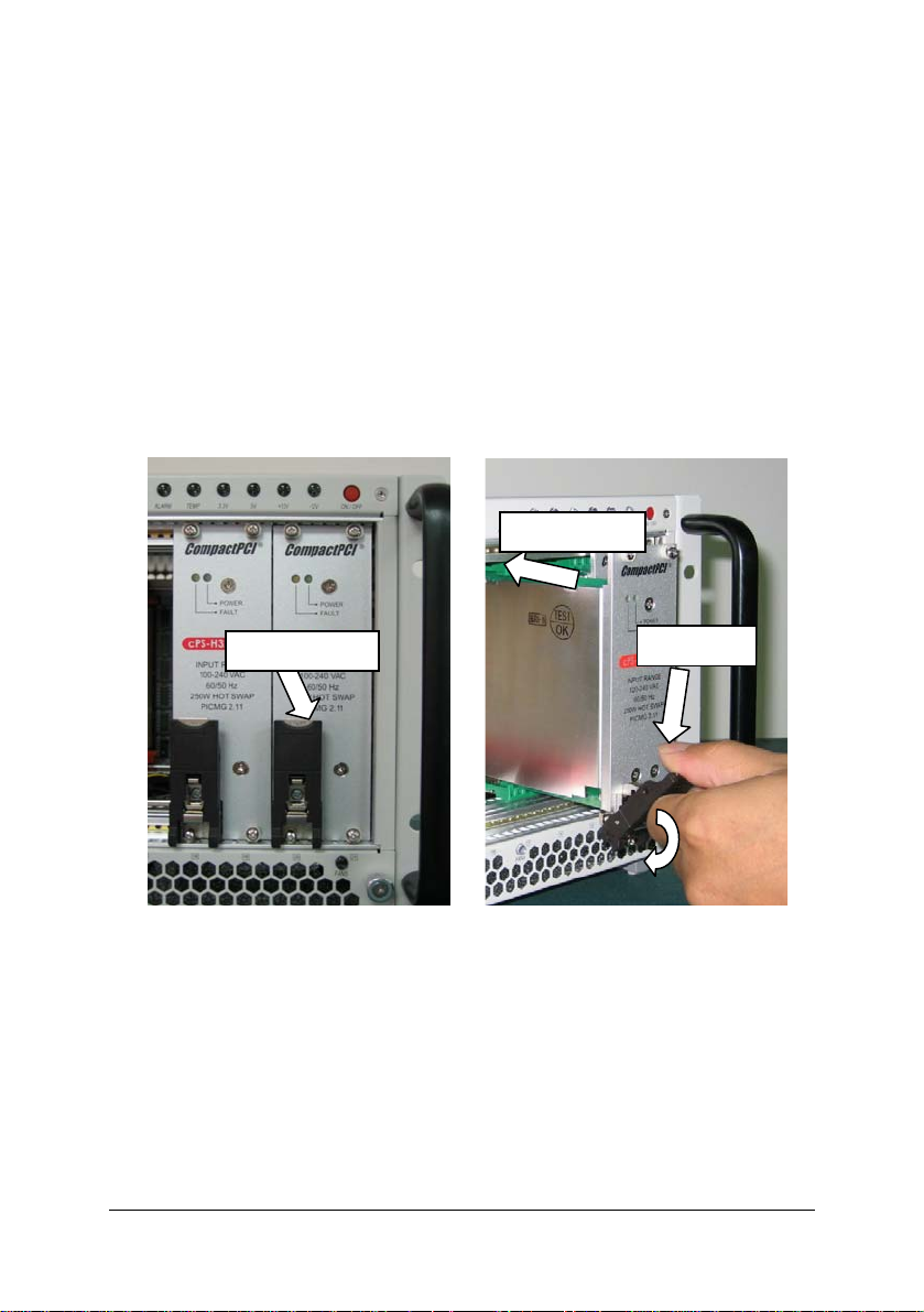
2. Hold the SBC module, peripheral card or PSU module vertically. For PSU
modules, make sure that the handle is unlatched (i.e. that it is pulled
downwards) by first pressing on the locking button with your thumb.
Insert Module
Locking Button
Unlatched
3. Carefully insert the module into the desired slot by sliding the edges of the
board into the appropriate card guide rail. Take care to ensure correct
alignment of the card with the chassis during insertion to prevent damage
to the card and/or backplane.
4. Continue inserting the card until the handle engages with the chassis.
5. Pull upwards on the handle for final insertion. For PSU modules, ensure
that the locking button on the handle is fully latched into positi on.
Backplane • 7
Page 14
y
Fully Latched
Handle Engages
with Chassis
System Card
Full
Inserted
To remove the module, press the release button (if necessary), and reverse
steps 1 through 5 above.
8 • Backplane
Page 15
2.3 RTM (Rear Transition Module) Installation
The installation and removal procedures for a RTM are the same as those for
CompactPCI boards. Because they are shorter than front boards, pay careful
attention when inserting or removing RTMs. Only models with an “R” at the end
of the model number support RTMs.
Note: We strongly recommended the use of RTMs with AB type connectors
to prevent damaging the backplane during RTM installation.
2.4 Powering Up the System
Connect the supplied power cord to the socket on the back of the chassis. All
supplied PSUs are full range 90-240VAC and do not require input voltage
setting. Insert a system module into the appropriate card slot.
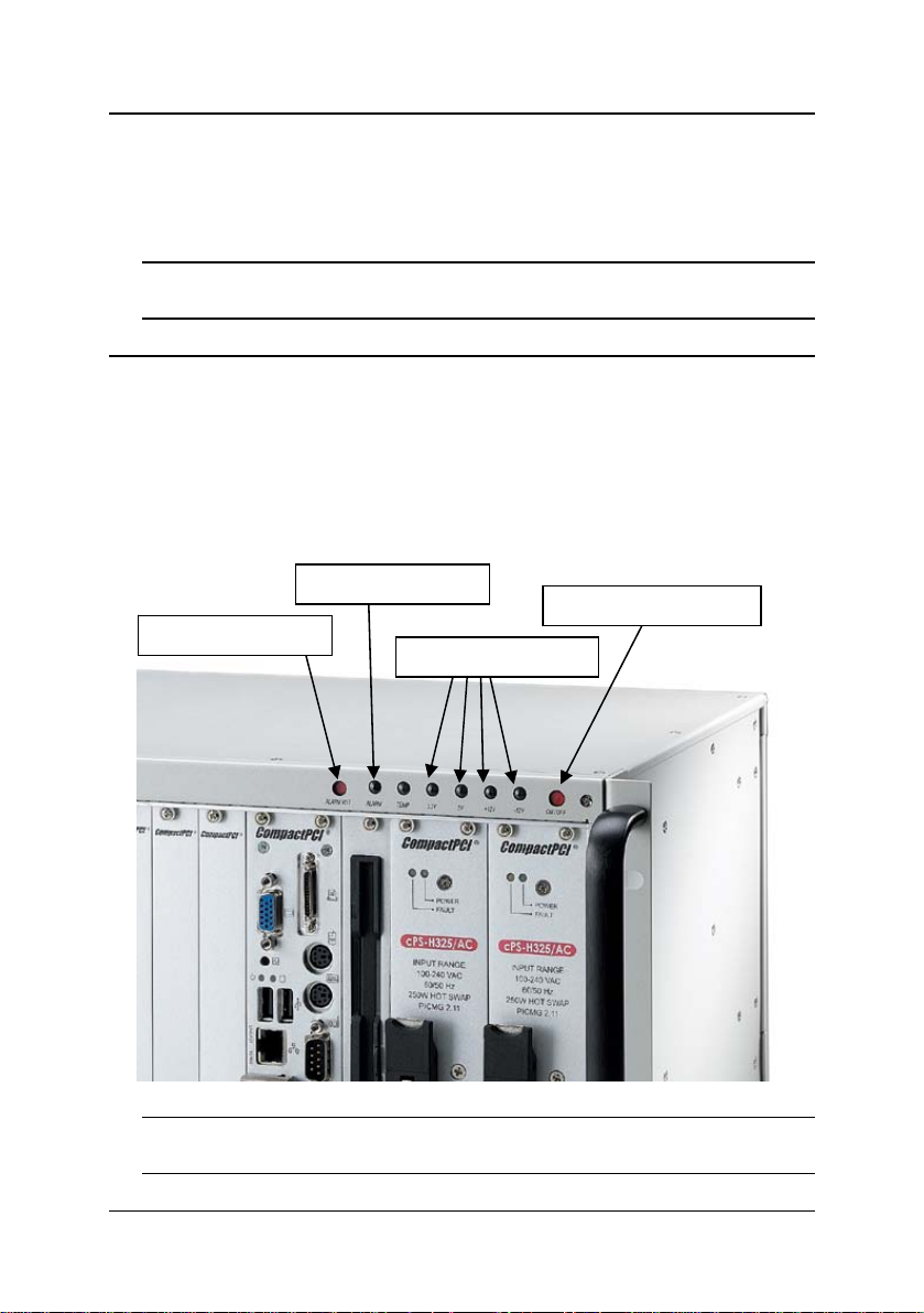
The cPCIS-ET2600 Series subsystems feature a guarded po wer switch. Use
a suitably shaped object (such as a pen) to actuate the power switch. All
LEDs will light up to indicate normal operating conditions.
Alarm LED
Alarm reset switch
Voltage Status LEDs
Guarded Power Switch
Note: If there are any faults with the power supply,
the appropriate Voltage Status LED will turn off to notify the user.
Backplane • 9
Page 16

3 Backplane
In this chapter, we will describe the backplane for the cPCIS-ET 2600 Series
subsystems. The following table specifies the backplane(s) that corres pond
to each model.
backplane slots
cPCIS-ET2632[R] cBP-3208[R] 8 cBP-3062A
power
backplane
3.1 cBP-3208[R] Backplane
The cBP-3208[R] is a 3U CompactPCI 32-bit backplane with optional rear I/O
(designated by an “R” suffix). It is used by the cPCIS-2630 / 2631 / 2632 /
2650 / 2651[R].
Specifications
• Standard CompactPCI height for 3U cPCI cards
• CompactPCI Compliancy
o PICMG 2.0 CompactPCI core specification R3.0
o PICMG 2.1 CompactPCI hot swap R2.0
• Dimensions: 141.3 x 128.7 mm
• PCI bus clock: up to 32-bit/33MHz
• System Slot: one R-hand side dual-slot
• System Slot Rear I/O: P2 rear I/O with AB-type shroud
• Peripheral slots: 7
• Peripheral Slots Rear I/O: P2 rear I/O with AB-type shroud (optional)
• Power Connectors: ATX connector x2, DC screw terminals
• V (I/O): 3.3V or 5V selectable, default 5V
• Other connectors: INH#, Reset, PWR_FAL#
10 • Backplane
Page 17

Mechanical Drawing
8 - P2
8 - P1
cBP-3208[R]Front View
1 - P2
1 - P1
Backplane • 11
Page 18

1 - P2
Optional Rear I/O: 2 - P2 to 8 - P2
12 • Backplane
cBP-3208[R] Rear View
Page 19

Pin Assignment
¾ [1 – P1] System Slot
Pin Z A B C D E F
GND +5V REQ64#
25
GND AD[1] +5V V(I/O)
24
GND +3.3V AD[4] AD[3] +5V AD[2] GND
23
GND AD[7] GND +3.3V AD[6] AD[5] GND
22
GND +3.3V AD[9] AD[8] M66EN C/BE[0]# GND
21
GND AD[12] GND V(I/O)
20
GND +3.3V AD[15] AD[14] GND AD[13] GND
19
GND SERR# GND +3.3V PAR C/BE[1]# GND
18
GND +3.3V IPMB_SCL
17
GND DEVSEL# GND V(I/O)
16
GND +3.3V FRAME# IRDY# BDSEL TRDY# GND
15
12-14 Key
GND AD[18] AD[17] AD[16] GND C/BE[2]# GND
11
GND AD[21] GND +3.3V AD[20] AD[19] GND
10
GND C/BE[3]# IDSEL AD[23] GND AD[22] GND
9
GND AD[26] GND V(I/O)
8
GND AD[30] AD[29] AD[28] GND AD[27] GND
7
GND REQ# GND +3.3V CLK AD[31] GND
6
GND Reserved
5
GND IPMB_PWR HEALTHY# V(I/O)
4
GND INTA# INTB# INTC# +5V INTD# GND
3
GND TCK
2
GND +5V -12V TRST#
1
Reserved PCIRST# GND GNT# GND
+5V TMS
Pin Z A B C D E F
ENUM# +3.3V +5V GND
AD[0] ACK64# GND
AD[11] AD[10] GND
IPMB_SDA GND PERR# GND
STOP# LOCK# GND
AD[25] AD[24] GND
INTP INTS GND
TDO TDI
+12V +5V GND
GND
Backplane • 13
Page 20

¾ [1 – P2] System Slot
Pin Z A B C D E F
22 GND GA4
21 GND CLK6 GND NC NC NC GND
20 GND CLK5 GND NC NC NC GND
19 GND GND GND NC NC NC GND
18 GND NC NC NC NC NC GND
17 GND NC NC PRST# REQ6# GNT6# GND
16 GND NC NC DEG# NC NC GND
15 GND NC NC FAL# REQ5# GNT5# GND
14 GND NC NC NC NC NC GND
13 GND NC NC NC NC NC GND
12 GND NC NC NC NC NC GND
11 GND NC NC NC NC NC GND
10 GND NC NC NC NC NC GND
9 GND NC NC NC NC NC GND
8 GND NC NC NC NC NC GND
7 GND NC NC NC NC NC GND
6 GND NC NC NC NC NC GND
5 GND NC NC NC NC NC GND
4 GND V(I/O) NC NC NC NC GND
3 GND CLK4 GND GNT3# REQ4# GNT4# GND
2 GND CLK2 CLK3 GND GNT2# REQ3# GND
1 GND CLK1 GND REQ1# GNT1# REQ2# GND
Pin Z A B C D E F
GA3 GA2 GA1 GA0 GND
14 • Backplane
Page 21

¾ [2 – P1] / [8 – P1] Peripheral Slot
Pin Z A B C D E F
25 GND +5V REQ64# ENUM# +3.3V +5V GND
24 GND AD[1] +5V V(I/O) AD[0] ACK64# GND
23 GND +3.3V AD[4] AD[3] +5V AD[2] GND
22 GND AD[7] GND +3.3V AD[6] AD[5] GND
21 GND +3.3V AD[9] AD[8] M66EN C/BE[0]# GND
20 GND AD[12] GND V(I/O) AD[11] AD[10] GND
19 GND +3.3V AD[15] AD[14] GND AD[13] GND
18 GND SERR# GND +3.3V PAR C/BE[1]# GND
17 GND +3.3V IPMB_SCL IPMB_SDA GND PERR# GND
16 GND DEVSEL# GND V(I/O) STOP# LOCK# GND
15 GND +3.3V FRAME# IRDY# GND TRDY# GND
12-14 Key
11 GND AD[18] AD[17] AD[16] GND C/BE[2]# GND
10 GND AD[21] GND +3.3V AD[20] AD[19] GND
9 GND C/BE[3]# IDSEL AD[23] GND AD[22] GND
8 GND AD[26] GND V(I/O) AD[25] AD[24] GND
7 GND AD[30] AD[29] AD[28] GND AD[27] GND
6 GND REQ# GND +3.3V CLK AD[31] GND
5 GND NC NC PCIRST# GND GNT# GND
4 GND IPMB_PWR HEALTHY# V(I/O) INTP INTS GND
3 GND INTA# INTB# INTC# +5V INTD# GND
2 GND TCK +5V TMS TDO TDI GND
1 GND +5V -12V TRST# +12V +5V GND
Pin Z A B C D E F
¾ [2 – P2] / [8 – P2] Peripheral Slot
Pin Z A B C D E F
22 GND
1-21 GND NC NC NC NC NC GND
GA4
GA3 GA2 GA1 GA0
GND
Backplane • 15
Page 22

¾ CN1 / CN2 – ATX Power Connector
1
11
¾ JP7 – connector
1
¾ JP8 – connector
1
¾ JP9 – connector
1
¾ JP10 – connector
1
¾ JP1- V (I/O), default: +5V
1
8
16 • Backplane
Pin Signal Pin Signal
1 +3.3V 11 +3.3V
2 +3.3V 12 -12V
3 GND 13 GND
4 +5V 14 PS_ON_L
5 GND 15 GND
6 +5V 16 GND
7 GND 17 GND
8 POWER
9 5V STB 19 +5V
10 +12V 20 +5V
Pin # Signal Name
1
2
Pin # Signal Name
1
2
Pin # Signal Name
1 PRST#
2 GND
Pin # Signal Name
1 FAL#
2 GND
Pin # Signal Name Pin # Signal Name
1 +12V 2 GND
3 -12V 4 GND
5 +3.3V 6 GND
7 +5V 8 GND
18 -5V
GOOD
+12V
-12V Sense
INH#
GND
Page 23

3.2 cBP-3206[R] Backplane
The cBP-3206[R] is a 3U CompactPCI 32-bit backplane with optional rear I/O
(designated by an “R” suffix). The cPCIS-2642[R] uses two of these backplanes.
Specifications
• Standard CompactPCI height for 3U cPCI cards
• CompactPCI Compliancy
o PICMG 2.0 CompactPCI core specification R3.0
o PICMG 2.1 CompactPCI hot swap R2.0
• Dimensions: 100.7 x 128.7 mm
• PCI bus clock: up to 32-bit/33MHz
• System Slot: one R-hand side dual-slot
• System Slot Rear I/O: P2 rear I/O with AB-type shroud
• Peripheral slots: 5
• Peripheral Slots Rear I/O: P2 rear I/O with AB-type shroud (optional)
• Power Connectors: ATX connector x2, DC screw terminals
• V (I/O): 3.3V or 5V selectable, default 5V
• Other connectors: INH#, Reset, PWR_FAL#
Backplane • 17
Page 24

[R]
Mechanical Drawing
6 - P2
6 - P1
1 - P2
1 - P1
JP8 - JP10
CN1
cBP-3206
1 - P2
Front View
Opt. Rear I/O:
2 - P2 to 6 - P2
CN2
cBP-3206[R]Rear View
18 • Backplane
Page 25

Pin Assignment
¾ [1 – P1] System Slot
Pin Z A B C D E F
GND +5V REQ64#
25
GND AD[1] +5V V(I/O)
24
GND +3.3V AD[4] AD[3] +5V AD[2] GND
23
GND AD[7] GND +3.3V AD[6] AD[5] GND
22
GND +3.3V AD[9] AD[8] M66EN C/BE[0]# GND
21
GND AD[12] GND V(I/O)
20
GND +3.3V AD[15] AD[14] GND AD[13] GND
19
GND SERR# GND +3.3V PAR C/BE[1]# GND
18
GND +3.3V IPMB_SCL
17
GND DEVSEL# GND V(I/O)
16
GND +3.3V FRAME# IRDY# BDSEL TRDY# GND
15
12-14 Key
GND AD[18] AD[17] AD[16] GND C/BE[2]# GND
11
GND AD[21] GND +3.3V AD[20] AD[19] GND
10
GND C/BE[3]# IDSEL AD[23] GND AD[22] GND
9
GND AD[26] GND V(I/O)
8
GND AD[30] AD[29] AD[28] GND AD[27] GND
7
GND REQ# GND +3.3V CLK AD[31] GND
6
GND Reserved
5
GND IPMB_PWR HEALTHY# V(I/O)
4
GND INTA# INTB# INTC# +5V INTD# GND
3
GND TCK
2
GND +5V -12V TRST#
1
Reserved PCIRST# GND GNT# GND
+5V TMS
Pin Z A B C D E F
ENUM# +3.3V +5V GND
AD[0] ACK64# GND
AD[11] AD[10] GND
IPMB_SDA GND PERR# GND
STOP# LOCK# GND
AD[25] AD[24] GND
INTP INTS GND
TDO TDI
+12V +5V GND
GND
Backplane • 19
Page 26

¾ [1 – P2] System Slot
Pin Z A B C D E F
22 GND GA4
21 GND CLK6 GND NC NC NC GND
20 GND CLK5 GND NC NC NC GND
19 GND GND GND NC NC NC GND
18 GND NC NC NC NC NC GND
17 GND NC NC PRST# REQ6# GNT6# GND
16 GND NC NC DEG# NC NC GND
15 GND NC NC FAL# REQ5# GNT5# GND
14 GND NC NC NC NC NC GND
13 GND NC NC NC NC NC GND
12 GND NC NC NC NC NC GND
11 GND NC NC NC NC NC GND
10 GND NC NC NC NC NC GND
9 GND NC NC NC NC NC GND
8 GND NC NC NC NC NC GND
7 GND NC NC NC NC NC GND
6 GND NC NC NC NC NC GND
5 GND NC NC NC NC NC GND
4 GND V(I/O) NC NC NC NC GND
3 GND CLK4 GND GNT3# REQ4# GNT4# GND
2 GND CLK2 CLK3 GND GNT2# REQ3# GND
1 GND CLK1 GND REQ1# GNT1# REQ2# GND
Pin Z A B C D E F
GA3 GA2 GA1 GA0 GND
20 • Backplane
Page 27

¾ [2 – P1] – [6 – P1] Peripheral Slot
Pin Z A B C D E F
25 GND +5V REQ64# ENUM# +3.3V +5V GND
24 GND AD[1] +5V V(I/O) AD[0] ACK64# GND
23 GND +3.3V AD[4] AD[3] +5V AD[2] GND
22 GND AD[7] GND +3.3V AD[6] AD[5] GND
21 GND +3.3V AD[9] AD[8] M66EN C/BE[0]# GND
20 GND AD[12] GND V(I/O) AD[11] AD[10] GND
19 GND +3.3V AD[15] AD[14] GND AD[13] GND
18 GND SERR# GND +3.3V PAR C/BE[1]# GND
17 GND +3.3V IPMB_SCL IPMB_SDA GND PERR# GND
16 GND DEVSEL# GND V(I/O) STOP# LOCK# GND
15 GND +3.3V FRAME# IRDY# GND TRDY# GND
12-14 Key
11 GND AD[18] AD[17] AD[16] GND C/BE[2]# GND
10 GND AD[21] GND +3.3V AD[20] AD[19] GND
9 GND C/BE[3]# IDSEL AD[23] GND AD[22] GND
8 GND AD[26] GND V(I/O) AD[25] AD[24] GND
7 GND AD[30] AD[29] AD[28] GND AD[27] GND
6 GND REQ# GND +3.3V CLK AD[31] GND
5 GND NC NC PCIRST# GND GNT# GND
4 GND IPMB_PWR HEALTHY# V(I/O) INTP INTS GND
3 GND INTA# INTB# INTC# +5V INTD# GND
2 GND TCK +5V TMS TDO TDI GND
1 GND +5V -12V TRST# +12V +5V GND
Pin Z A B C D E F
¾ [2 – P2] – [6 – P2] Peripheral Slot
Pin Z A B C D E F
22 GND
1-21 GND NC NC NC NC NC GND
GA4
GA3 GA2 GA1 GA0
GND
Backplane • 21
Page 28

¾ CN1 / CN2 – ATX Power Connector
Pin Signal Pin Signal
1
¾ JP8 – connector
¾ JP9 – connector
¾ JP10 – connector
11
1 +3.3V 11 +3.3V
2 +3.3V 12 -12V
3 GND 13 GND
4 +5V 14 PS_ON_L
5 GND 15 GND
6 +5V 16 GND
7 GND 17 GND
8 POWER
GOOD
9 5V STB 19 +5V
10 +12V 20 +5V
Pin # Signal Name
1
1
2
Pin # Signal Name
1
1
2
Pin # Signal Name
1
1 FAL#
2 GND
18 -5V
INH#
-12V Sense
PRST#
GND
22 • Backplane
Page 29

3.3 cBP-3061 Power Backplane
The cBP-3061 is a PICMG 2.11 CompactPCI 3U 47-pin power backplane for
one power module. It is used by the cPCIS-2631/2642[R].
Specifications
• CompactPCI Compliancy: PICMG 2.11 CompactPCI Power Interface
• Dimensions: 40.64x 128.7 mm
• Power Module Sockets: one
• AC/DC input screw terminal: yes
• DC output (ATX connector): one
• Cascading voltage Sense: Built-in ATX connector
• INH#/FAL#/DEG# Distribution: Built-in ATX connector
Mechanical Drawing
CN4
CN1
CN9
CN7
CN2
CN3
CN6
CN5
CN8
cBP-3061 [R]RearViewcBP-3061[R]Front View
Backplane • 23
Page 30

Pin Assignment
¾ CN1 – Power Sense Connector
1
¾ CN2 – Power Sense Connector
1
¾ CN3 – connector
1
Pin # Signal Name
1
2
3
4
5
V1_Sense
GND_S
V2_Sense
V3_Sense
NC
Pin # Signal Name
1
2
3
4
5
V1_Sense
GND_S
V2_Sense
V3_Sense
NC
Pin # Signal Name
1
2
INHJ
GND
24 • Backplane
Page 31

¾ CN4 – Modular Power 47P Connector
Pin Signal Pin Signal
47
44
42
47 ACL/-DC IN 31 GA2
46 ACN/+DC IN 30 V1 SENSE
45 CGND 29 V1ADJ
44 V3 SHARE 28 GA1
43 IPMB_PWR 27 EN#
42 +FAL# 26 RESERVED
41 V2 SHARE 25 GA0
23
20
21
19
40 IPMB_SDA 24 RTN
39 INH# 23 RESERVED
38 DEG# 22 RTN
37 IPMB_SCL 21 V4
36 V3 SENSE 20 V3
35 V1 SHARE 19 RTN
34 S RTN 13-18 V2
33 V2 SENSE 5-12 RTN
32 V2ADJ 1-4 V1
2
1
¾ CN5 – Current Share Connector
Pin # Signal Name
1
2
3
4
1
5
¾ CN6 – Current Share Connector
Pin # Signal Name
1
2
3
4
1
5
V1_Share
GND
V2_Share
V3_Share
NC
V1_Share
GND
V2_Share
V3_Share
NC
Backplane • 25
Page 32

¾ CN7 –AC/DC in Let Connector
1
¾ CN8 – IPMB Connector
1
¾ CN9 – ATX Power Connector
Pin Signal Pin Signal
1
11
1 +3.3V 11 +3.3V
2 +3.3V 12 -12V
3 GND 13 GND
4 +5V 14 PS_ON_L
5 GND 15 GND
6 +5V 16 GND
7 GND 17 GND
8 POWER
9 5V STB 19 +5V
10 +12V 20 +5V
Pin # Signal Name
1
2
3
ACN/DC+
ACL/DC-
CGND
Pin # Signal Name
1
2
3
4
5
IPMB_SCL
GND
IPMB_SDA
IPMB_PWR
ALERT
18 -5V
GOOD
26 • Backplane
Page 33

3.4 cBP-3062 Power Backplane
The cBP-3062 is a PICMG 2.11 CompactPCI 3U 47-pin power backplane for
two power modules. It is used by the cPCIS-ET2632[R].
Specifications
• CompactPCI Compliancy: PICMG 2.11 CompactPCI Power
Interface
• Dimensions: 40.64x 128.7 mm
• Power Module Sockets: two
• AC/DC input screw terminal: yes
• DC output (ATX connector): two
• Cascading Current Sharing: yes
• Cascading Voltage Sense: Built-in ATX connector
• INH#/FAL#/DEG# Distribution: Selectable common
INH#/FAL#/DEG# or separated INH# for each power module,
dedicated connector
• PICMG 2.0 IPMB Socket: yes
Mechanical Drawing
CN3
CN1
CN2
CN8
CN10 CN9
CN5
CN4
Backplane • 27
CN7
Page 34

Pin Assignment
¾ CN1 / CN2 – Modular Power 47P Connector
Pin Signal Pin Signal
47
44
23
20
2
¾ CN3 –AC/DC in Let Connector
1
¾ CN4 – Power Sense Connector
1
47 ACL/-DC IN 31 GA2
46 ACN/+DC IN 30 V1 SENSE
45 CGND 29 V1ADJ
44 V3 SHARE 28 GA1
4
43 IPMB_PWR 27 EN#
2
42 +FAL# 26 RESERVED
41 V2 SHARE 25 GA0
40 IPMB_SDA 24 RTN
21
39 INH# 23 RESERVED
19
38 DEG# 22 RTN
37 IPMB_SCL 21 V4
36 V3 SENSE 20 V3
35 V1 SHARE 19 RTN
34 S RTN 13-18 V2
33 V2 SENSE 5-12 RTN
32 V2ADJ 1-4 V1
1
Pin # Signal Name
1
2
3
ACN/DC+
ACL/DC-
Pin # Signal Name
1
2
3
4
V1_Sense
GND_S
V2_Sense
V3_Sense
5
cBP-3062[R]RearViewcBP-3062[R]Front View
CGND
NC
28 • Backplane
Page 35

¾ CN5 – Power Sense Connector
Pin # Signal Name
1
¾ CN6 –Connector
Pin # Signal Name
1
¾ CN7 – Current Share Connector
Pin # Signal Name
1
¾ CN8 – Current Share Connector
Pin # Signal Name
1
1
2
3
4
5
V1_Sense
GND_S
V2_Sense
V3_Sense
NC
1
2
3
4
5
IPMB_SCL
GND
IPMB_DA
IPMB_PWR
ALERT
1
2
3
4
5
V1CS
GND_S
V2 CS
V3 CS
NC
1
2
3
4
5
V1 CS
GND_S
V2 CS
V3 CS
NC
Backplane • 29
Page 36

¾ CN9 / CN10 – ATX Power Connector
Pin Signal Pin Signal
1
¾ JP1 – connector
¾ JP2 – connector
¾ JP3 – connector
¾ JP4 – connector
11
1 +3.3V 11 +3.3V
2 +3.3V 12 -12V
3 GND 13 GND
4 +5V 14 PS_ON_L
5 GND 15 GND
6 +5V 16 GND
7 GND 17 GND
8 POWER
GOOD
9 5V STB 19 +5V
10 +12V 20 +5V
Pin # Signal Name
1
1
2
Pin # Signal Name
1
1
1
2
Pin # Signal Name
1
2
3
4
5
8
6
7
8
Pin # Signal Name
1
1
2
18 -5V
INH#2
GND
INH#1
GND
DEG#1
FAL#1
RSV23A
RSV26A
DEG#2
FAL#2
RSV23B
RSV26B
INH#
GND
30 • Backplane
Page 37

4 Cooling System
The cPCIS-ET2600 Series subsystems with CompactPCI PSUs are
equipped five front-access hot swappable low noise fans on the bottom of the
chassis to provide an effectively cooled environment. The fans are push-in
and ventilate out the rear of the chassis. The chassis is equipped with air
filters that are removable for cleaning and replacement. An embedded alarm
board monitors fan status and initiates a visible and audi ble alarm upon fan
failure.
4.1 Removing and Replacing the Air Filters
cPCIS-ET2600 Series models with CompactPCI PSU(s)
To ensure proper performance, the air filters of cPCIS-ET2600 Series
subsystems with CompactPCI PSUs should be cleaned or replaced as
necessary. Replacement air filters are supplied and can be found in the
Accessory Packet.
Air Filter Removal and Replacement Procedure
1. Remove the screws attaching the front filter cover at the base of the
chassis (2 screws) and remove the cover.
Cooling System • 31
Page 38

2. After cleaning or replacing the filter, place it back in position and reattach the filter cover.
3. Remove the screws attaching the bottom filter cover on the bottom
of the chassis (6 screws – see diagram below).
4. After cleaning or replacing the filter, place it back in positi on and reattach the filter cover.
32 • Cooling System
Page 39

4.2 Fan Alarm: Fan Removal and Replacement
The embedded alarm board monitors temperature & fan status. Should a fan
become disabled, the Alarm LED will light up and an audible warning will be
heard. The LED corresponding to the faulty fan will flash, indicating which fan
needs to be replaced.
To disable the audible warning, press the Alarm RST button. The Alarm LED
will continue to flash until the faulty fan is replaced.
Alarm Reset
Fan Removal and Installation Procedure (cPCI PSU models)
Alarm LED
Temperature LED
1. Remove the screws attaching the front filter cover at the base of the
chassis (2 screws) and remove the cover (see
and Replacement Procedure
above).
Air Filter Removal
2. Pull the faulty fan module out of the fan tray and replace with a
functional fan.
3. Reverse steps 1-2 to replace the filter cover.
For replacement fan modules, please contact your ADLINK distributor.
Cooling System • 33
Page 40

4.3 Temperature Alarm
When the subsystem's internal temperature exceeds 50°C, the TEMP LED
will flash and an audible warning will be heard. To reset the alarm and
disable the audible warning, press the Alarm RST button.
In order to protect the system from damage resulting from overheating, it
should be shut down immediately. Inspect the operating environment for
causes of the overheating condition. After the system has cooled down
sufficiently, power it up and be observant of any future temperature alarm
conditions.
4.4 Fan Specifications
• Model: ADDA AD0812XB-D93GP
• Dimensions: 80 x 80 x 15mm.
• Weight: 63 Gram.
• Type: 12VDC brush-less with ball bearing motor.
• Rated voltage: 12V @ 0.38A.
• Rated power: 4.56 W each.
• Fan speed: 4000 RPM.
• Maximum Air flow: 46.3 CFM each (when zero static pressure).
• Noise: 42.7 dBA each.
Mechanical Drawing
34 • Cooling System
Page 41

5 Power Supply Unit
The cPCIS-ET2600 Series subsystems are equipped with ADLINK’s cPSP325/AC CompactPCI power module.
5.1 CompactPCI: cPS-P325/AC
Features
• 250W 3U X 8HP Eurocard package
• Meets EN 61000-3-2 active power factor correction
• Internal OR-ing diodes for N+1 redundancy
• Hot-swappable
• Active current sharing
• EMI meets EN 55022 / FCC CLASS A
• CE marking compliance
• Fully compliant with PICMG
Specifications
• Operating Temperature Range: -25°C to +50°C
• Storage Temperature: -40 to +85
• Temperature Coefficient: Typ. ±0.3% /
• Cooling: >400 LFM moving air required to achieve full rate d power
• Dimensions: Eurocard 3U X 8HP X 160mm CompactPCI format
• Efficiency: 81.5-82.6% typical
• Switching Frequency: 135K Hz
• Safety: IEC60950-1,CSA60950-1 & China CCC
• Circuit Topology: Forward circuit
°C
°C
Power Supply Unit • 35
Page 42

Input Characteristics
• Input Voltage: Typ. 90-264VAC
• Power Factor Correction: Meets Harmonic Correction
• Input Connector: CompactPCI 47-pin power connector
• Input Frequency: 47-63Hz
• Inrush Current: Less than 15A@240VAC
• Input Current: 3.6A@230VAC/ 4A@260VAC
• EMI: Meets EN55022 / FCC Class A
• Hold-up Time: 20mS after power fail signal
• Remote ON/OFF: Available at [INH#] & [EN#] pins
• Power Fail Signal: Available at [FAL#] pin
• Status LED: <Green> means valid input voltage; <Amber> means a
critical fault.
• Thermal Protection (OTP): Installed NTC and thermostat for thermal
sensor at [DEG#] pin
• Power OK: Installed at all outputs
• Leakage Current: 1.18mA at 254VAC/60Hz
Output Characteristics
EN 61000-3-2
.
Output
Voltage
5V
3.3V
12V
-12V
• Over Load Protection: Fully protected against output overload or
short circuit. Typical 120% max. load.
• Over Current Protection: Installed at each rail
• Output Wattage: Typ. 250W continuous.
• Output Connector: CompactPCI 47-pin power connector.
• Line Regulation: Max. ±10mV
• Load Regulation: 3.3V & 5V: ± 10mV, +12V: ± 30mV & -12V: -380
mV.
36 • Power Supply Unit
Min. Max. Typ. Peak
Output Current (A)
0 40.0 25.0 –
0 40 20 –
0 5.5 4 –
0 2 1 –
Page 43

• Noise & Ripple: 60 mV@5V and 3.3V output; 120mV@.± 12V
output.
• OVP: Built-in at all outputs.
• Adjustability: Available at VO1, 2 & 3.
• Output Trim: Electrical trim available at VO1/VO2 [ADJ #].
• Remote Sensing: Available at VO1, VO2 & VO3.
• Hot-Swap: Available.
• N+1 Redundancy: Installed with internal OR-ing diodes at all outputs
for N+1 redundancy operation.
• Current Sharing: Third-wire c urrent sharing at VO1,2 &3.
• Power OK Signal: Available for all output.
• Over Current Protection: Installed at each rail.
• Overload Protection: Fully protected against output overload or short
circuit. Typical 120% max. load.
Output power versus temperature T
A
at V
i nom
Power Supply Unit • 37
Page 44

This page intentionally left blank.
38 • Power Supply Unit
Page 45

6 Specifications
6.1 Features
• Standard 19” Rack-mount 3U CompactPCI form factor (4U height).
• Board Space:
o Supports both front and rear access for I/O, CPU, and power supply.
o Standard 3U, 21-slot width chassis.
• Five front-access hot swappable fans with removable air filter for self-
cooling.
• Suitable for both rack-mount and desktop applications.
• Side handles for portability.
• Built-in alarm module to monitor chassis temperature and fan status.
• Comprehensive EMC shielding [EMC gaskets are installed on front rails
(top and bottom), rear rails, and side panels].
• Impact resistant power switch.
• Power status LEDs to easily monitor power status (+12V,-
12V,+5V,+3.3V).
6.2 Mechanical
• CompactPCI Standard: 2.0 R3.0.
• Form Factor: 3U CompactPCI with 50mm depth rear I/O.
• Enclosure: 19” 4U height rack-mount enclosure
o Coated metal plate outer covering.
o Guarded power switch and reset button.
• Dimensions: 448.4mm (W) x 177.8mm (H) x 258mm (D). Width with
rack-mounting kit is 482.6mm (19”).
• Usable width: 21 slots (84HP).
Specifications • 39
Page 46

6.3 Environmental
• Operating Temperature: -20°C to 50°C (Supports operation up to 70°C
but with derating above 50°C. Power efficiency will be derated by 2.5%
for every degree Celsius with only 50% power efficiency at 70°C, i.e.
125W/PSU.)
• Storage Temperature: -40 to 85°C.
• Humidity: 5% - 95%, non-condensed.
• Shock: 15G peak-to-peak, 11ms duration, non-operation.
• Vibration:
o Non-operation:1.88Grms, 5 – 500Hz, each axis.
o Operation: 0.5Grms, 5 – 500Hz, each axis.
6.4 System Alarm Board
• Supports fault alarm for up to 8 fans. If any fan faults, the ALARM LED
will flash and an audible alarm will sound
• Can detect temperature at two different locations.
• Trigger temperature for each sensor can be set independently (50°C,
60°C, 70°C).
• Alarm mute
• LED indicators for fan and temperature status
40 • Specifications
Page 47

Mechanical Drawing
Specifications • 41
Page 48

This page intentionally left blank.
42 • Specifications
Page 49

Important Safety Instructions
Read and follow all instructions marked on the product and in the
documentation before you operate your system. Retain all safety and operating
instructions for future use.
z Please read these safety instructions carefully.
z Please keep this User‘s Manual for later reference.
z The equipment can be operated at an ambient temperature of 50ºC.
z The equipment should be operated only from the type of power source
indicated on the rating label. Make sure the voltage of the power source
when connect the equipment to the power outlet.
z If your equipment has a voltage selector switch, make sure that the
switch is in the proper position for your area. The voltage selector switch
is set at the factory to the correct voltage.
z For pluggable equipment, that the socket-outlet shall be installed near the
equipment and shall be easily accessible.
z Place the power cord such a way that people can not step on it. Do not
place anything over the power cord.
z If the equipment is not use for long time, disconnect the equipment from
mains to avoid being damaged by transient overvoltage.
z All cautions and warnings on the equipment should be noted.
z Please keep this equipment from humidity.
z Do not use this equipment near water or a heat source.
z Lay this equipment on a reliable surface when install. A drop or fall could
cause injury.
z Never pour any liquid into opening; this could cause fire or electrical
shock.
z Openings in the case are provided for ventilation. Do not block or cover
these openings. Make sure you provide adequate space around the
system for ventilation when you set up your work area. Never insert
objects of any kind into the ventilation openings.
z To avoid electrical shock, always unplug all power cables and modem
cables from the wall outlets before removing covers.
Important Safety Instructions • 43
Page 50

z Lithium Battery provided (real time clock battery)
“CAUTION – Risk of explosion if battery is replaced by an incorrect
type. Dispose of used batteries according to the instructions”
z If one of the following situations arises, get the equipment checked by a
service personnel:
A. The power cord or plug is damaged.
B. Liquid has penetrated into the equipment.
C. The equipment has been exposed to moisture.
D. The equipment has not work well or you can not get it work
according to user‘s manual.
E. The equipment has dropped and damaged.
F. If the equipment has obvious sign of breakage.
44 • Important Safety Instruction
Page 51

Getting Service
ADLINK Technology, Inc.
Address: 9F, No.166 Jian Yi Road, Zhonghe District
New Taipei City 235, Taiwan
Tel: +886-2-8226-5877
Fax: +886-2-8226-5717
Email: service@adlinktech.com
Ampro ADLINK Technology, Inc.
Address: 5215 Hellyer Avenue, #110, San Jose, CA 95138, USA
Tel: +1-408-360-0200
Toll Free: +1-800-966-5200 (USA only)
Fax: +1-408-360-0222
Email: info@adlinktech.com
ADLINK Technology (China) Co., Ltd.
Address: 300 Fang Chun Rd., Zhangjiang Hi-Tech Park,
Pudong New Area, Shanghai, 201203 China
Tel: +86-21-5132-8988
Fax: +86-21-5132-3588
Email: market@adlinktech.com
ADLINK Technology Beijing
Address: Rm. 801, Power Creative E, No. 1, B/D
Shang Di East Rd., Beijing, 100085 China
Tel: +86-10-5885-8666
Fax: +86-10-5885-8625
Email: market@adlinktech.com
ADLINK Technology Shenzhen
Address: 2F, C Block, Bldg. A1, Cyber-Tech Zone, Gao Xin Ave. Sec. 7,
High-Tech Industrial Park S., Shenzhen, 518054 China
Tel: +86-755-2643-4858
Fax: +86-755-2664-6353
Email: market@adlinktech.com
LiPPERT ADLINK Technology GmbH
Address: Hans-Thoma-Strasse 11, D-68163, Mannheim, Germany
Tel: +49-621-43214-0
Fax: +49-621 43214-30
Email: emea@adlinktech.com
Getting Service • 45
Page 52

ADLINK Technology, Inc. (French Liaison Office)
Address: 15 rue Emile Baudot, 91300 Massy CEDEX, France
Tel: +33 (0) 1 60 12 35 66
Fax: +33 (0) 1 60 12 35 66
Email: france@adlinktech.com
ADLINK Technology Japan Corporation
Address: KANDA374 Bldg. 4F, 3-7-4 Kanda Kajicho,
Chiyoda-ku, Tokyo 101-0045, Japan
Tel: +81-3-4455-3722
Fax: +81-3-5209-6013
Email: japan@adlinktech.com
ADLINK Technology, Inc. (Korean Liaison Office)
Address: 8F Mointer B/D,1675-12, Seocho-Dong, Seocho-Gu,
Seoul 137-070, Korea
Tel: +82-2-2057-0565
Fax: +82-2-2057-0563
Email: korea@adlinktech.com
ADLINK Technology Singapore Pte. Ltd.
Address: 84 Genting Lane #07-02A, Cityneon Design Centre,
Singapore 349584
Tel: +65-6844-2261
Fax: +65-6844-2263
Email: singapore@adlinktech.com
ADLINK Technology Singapore Pte. Ltd. (Indian Liaison Office)
Address: 1st Floor, #50-56 (Between 16th/17th Cross) Margosa Plaza,
Margosa Main Road, Malleswaram, Bangalore-560055, India
Tel: +91-80-65605817, +91-80-42246107
Fax: +91-80- 23464606
Email: india@adlinktech.com
ADLINK Technology, Inc. (Israeli Liaison Office)
Address: 6 Hasadna St., Kfar Saba 44424, Israel
Tel: +972-9-7446541
Fax: +972-9-7446542
Email: israel@adlinktech.com
46 • Getting Service
 Loading...