

Page 1

cPCIS-2501
3U
CompactPCI
Cubic Chassis
User’s Guide
6-slot
Page 2

This page intentionally left blank.
Page 3
©Copyright 2005, 2010 ADLINK Technology Inc.
All Rights Reserved.
Manual Rev. 1.01, November 10, 2010
Part Number: 50-15041-1010
The information in this document is subject to change without prior notice in
order to improve reliability, design and function and does not represent a
commitment on the part of the manufacturer.
In no event will the manufacturer be liable for direct, indirect, special, incidental,
or consequential damages arising out of the use or inability to use the product
or documentation, even if advised of the possibility of such damages.
This document contains proprietary information protected by copyright. All
rights are reserved. No part of this manual may be reproduced by any
mechanical, electronic, or other means in any form without prior written
permission of the manufacturer.
Trademarks
Product names mentioned herein are used for identification purposes only and
may be trademarks and/or registered trademarks of their respective companies.
Revision History
Revision Date Changes
1.00 Mar. 15, 2005 Initial Release
1.01 Nov. 11, 2010 Update cooling fan specifications
Page 4
Getting Service from ADLINK
Customer Satisfaction is top priority for ADLINK TECHNOLOGY INC. If you
need any help or service, please contact us.
ADLINK TECHNOLOGY INC.
Web Site http://www.adlinktech.com
Sales & Service service@adlinktech.com
TEL +886-2-82265877 FAX +886-2-82265717
Address 9F, No. 166, Jian Yi Road, Chungho City, Taipei, 235 Taiwan
Please email or FAX your detailed information for prompt, satisfactory, and
consistent service.
Detailed Company Information
Company/Organization
Contact Person
E-mail Address
Address
Country
TEL FAX
Web Site
Questions
Product Model
OS:
Computer Brand:
M/B: CPU:
Environment
Detail Description
Chipset: BIOS:
Video Card:
NIC:
Other:
Suggestions for ADLINK
Page 5

Table of Contents
1 Introduction ....................................................................................1
1.1 Product Definition ......................................................................1
1.2 Features.....................................................................................2
1.3 Specifications.............................................................................2
1.4 Mechanical Drawing ..................................................................3
2 Getting Started ...............................................................................5
2.1 Shipping Contents .....................................................................5
2.2 CompactPCI Board & PSU Installation...................................... 5
2.3 Powering Up the System ...........................................................9
3 Backplane .....................................................................................11
3.1 cBP-3206 Backplane ...............................................................11
Specifications .....................................................................11
Mechanical Drawing ...........................................................12
Pin Assignment...................................................................13
3.2 cBP-3061 Power Backplane ....................................................17
Specifications .....................................................................17
Mechanical Drawing ...........................................................17
Pin Assignment...................................................................18
4 Cooling System ............................................................................21
4.1 Removing and Replacing the Air Filter ....................................21
4.2 Fan Removal and Replacement ..............................................23
5 Power Supply Unit .......................................................................25
5.1 CompactPCI: cPS-H325/AC ....................................................25
Features .............................................................................25
Specifications .....................................................................25
Input Characteristics........................................................... 26
Output Characteristics........................................................ 26
Important Safety Instructions............................................................29
Table of Contents • v
Page 6

This page intentionally left blank.
Page 7
1 Introduction
1.1 Product Definition
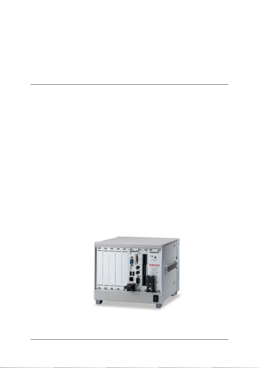
The cPCIS-2501 3U CompactPCI 6-slot Cubic Chassis is designed for 3U
CompactPCI cards and modules without rear I/O. It is 4U in height, 237 mm
deep, and suitable for bench top use or wall mounting. It is ideal for industrial
or transport applications where small chassis size and versatility are
important. A built in cooling system with removable filter provides maximum
cooling efficiency, and the 250W cPCI power supply allows easy
maintenance. The cPCIS-2501’s ability to handle a wide range of
temperatures and excellent shock and vibration characteristics make it
suitable for operating in a rigorous environment.
This user’s manual provides unpacking, operating, and maintenance
information for the cPCI-2501 3U CompactPCI 6-slot Cubic Chassis. The
cPCI-2501 chassis is assembled using the following components:
Components:
• Chassis: cPRK-2501
• Power Supply: cPS-H325/AC 3U cPCI
• Backplane: cBP-3206 6-slot 32-bit 3U cPCI
• Power Backplane: cBP-3061
cPCIS-2501 Front View
Introduction • 1
Page 8
1.2 Features
• Compact size, 4U high enclosure for 3U CompactPCI cards w/o rear I/O
• Board Space: 1 system slot, 5 peripheral slots, 1 PSU slot
• Side handle design for portable applications
• Stand feet on the bottom for desktop use
• Versatile wall-mount applications with mounting kit
• Standard PICMG 2.11 47-Pin modular power supply
• Built-in cooling system
• Bottom-access removable air filter for easy maintenance
1.3 Specifications
CompactPCI Standards
Form Factor
Enclosure
Cooling System Bottom-access removable fans for in-take:
Power Supply Power backplane: cBP-3061
Backplane
Chassis Partition
Dimension
Operating temperature
Storage temperature
Humidity
Shock
Vibration
Safety, Certification, EBS
PICMG 2.0 R3.0
3U CompactPCI card without rear I/O
Coated metal plate outer covering with aluminum
framework
12V DC brush-less, dual ball bearing
Two fans with 67.02 CFM/each
Rated speed for each fan: 4500 RPM
Rated power for each fan: 6 W
Supports single in-rack 3U cPCI 8HP power module
PICMG 2.11 47-pin power interface
Available power module: cPS-H325/AC (250W)
cBP-3206: 6-slot 32-bit 3U cPCI Backplane
5 slots for peripheral cards
3 slots for system module
2 slots for three 3U 8HP cPCI power modules
221.4 x 237 x 177 (mm, W x D x H, w/o wall mount kit
or stand feet)
0 to 60°C
-20 to 80°C
5% to 95%, non-condensing
15G peak-to-peak, 11ms duration, non-operation
Non-operation: 1.88Grms, 5-500Hz, each axis
CE
2 • Introduction
Page 9
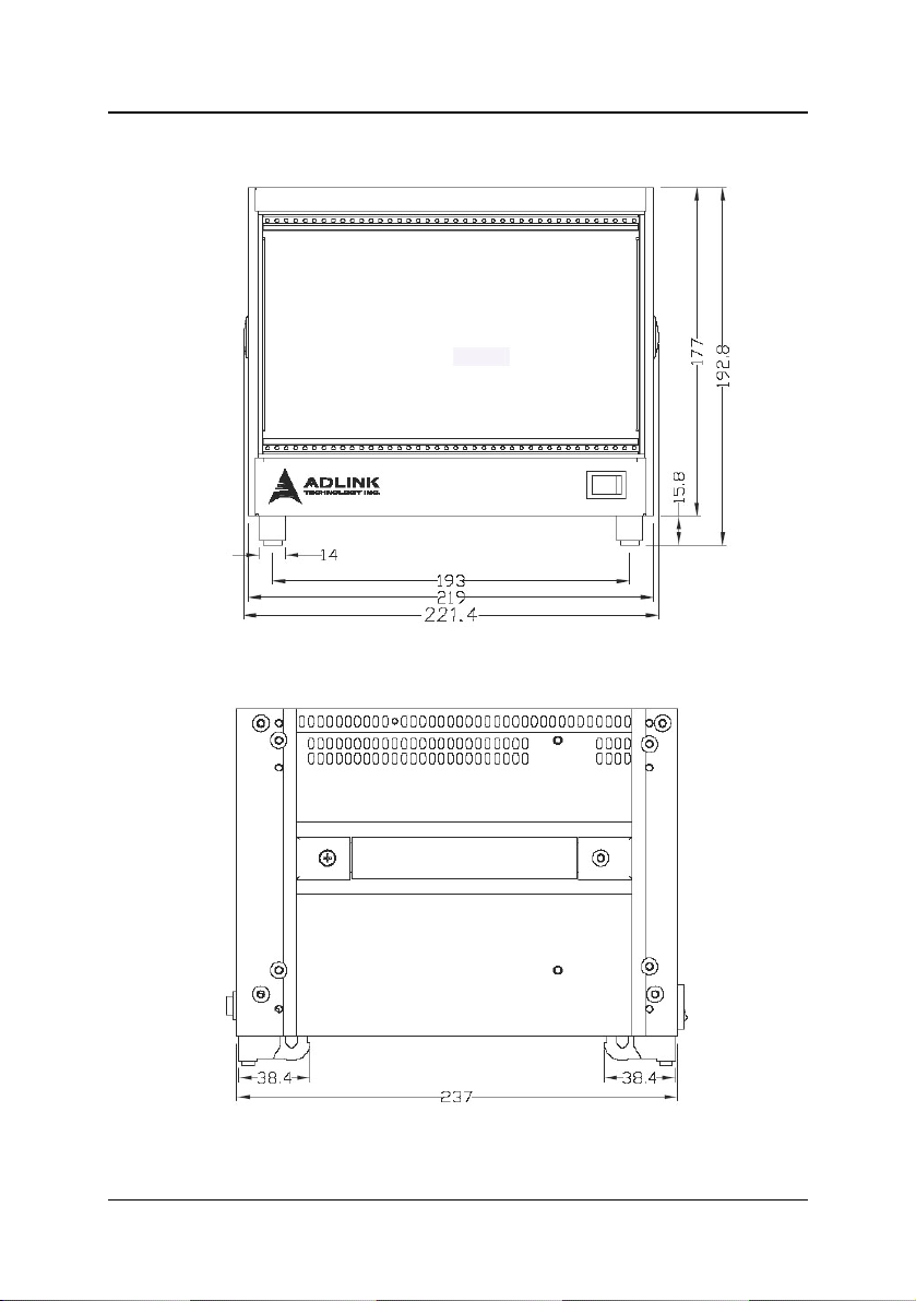
1.4 Mechanical Drawing
cPCIS-2501 Front View
cPCIS-2501 Side View
Introduction • 3
Page 10

This page intentionally left blank.
Page 11

2 Getting Started
In this chapter, we will describe the unpacking procedure for the cPCIS-2501
and installation procedures for CompactPCI boards and power supply unit
(PSU).
2.1 Shipping Contents
Check the shipping carton for any damage. If the shipping carton and
contents are damaged, please notify the dealer for a replacement. Retain
the shipping carton and packing material for inspection by the dealer. Obtain
authorization before returning any product to ADLINK.
Check that the following items are included in the package. If there are any
missing items, please contact your dealer:
• One cPCIS-2501 chassis
• cPS-H325/AC power supply
• This user’s manual
• Power cord (either N. American or European)
2.2 CompactPCI Board & PSU Installation
CompactPCI connectors are rigid, and therefore require careful handling
when inserted and removed. Improper manipulation of the cards will result in
damage to the backplane.
System slots usually have obvious indicators (e.g. red card guide rail, triangle
mark enclosing the slot number on the backplane, etc.). System cards can
only be installed in a system slot. Do not insert a system card into any other
slot, or insert any peripheral card into system slot.
The PSU slot also has an obvious indicator such as a green card guide rail in
a standard CompactPCI chassis (see photo below).
The handle on CompactPCI cards and PSUs ensures simple and safe
installation and removal. Please follow the procedures below to install a
CompactPCI module into the cPCIS-2501 chassis:
Getting Started • 5
Page 12
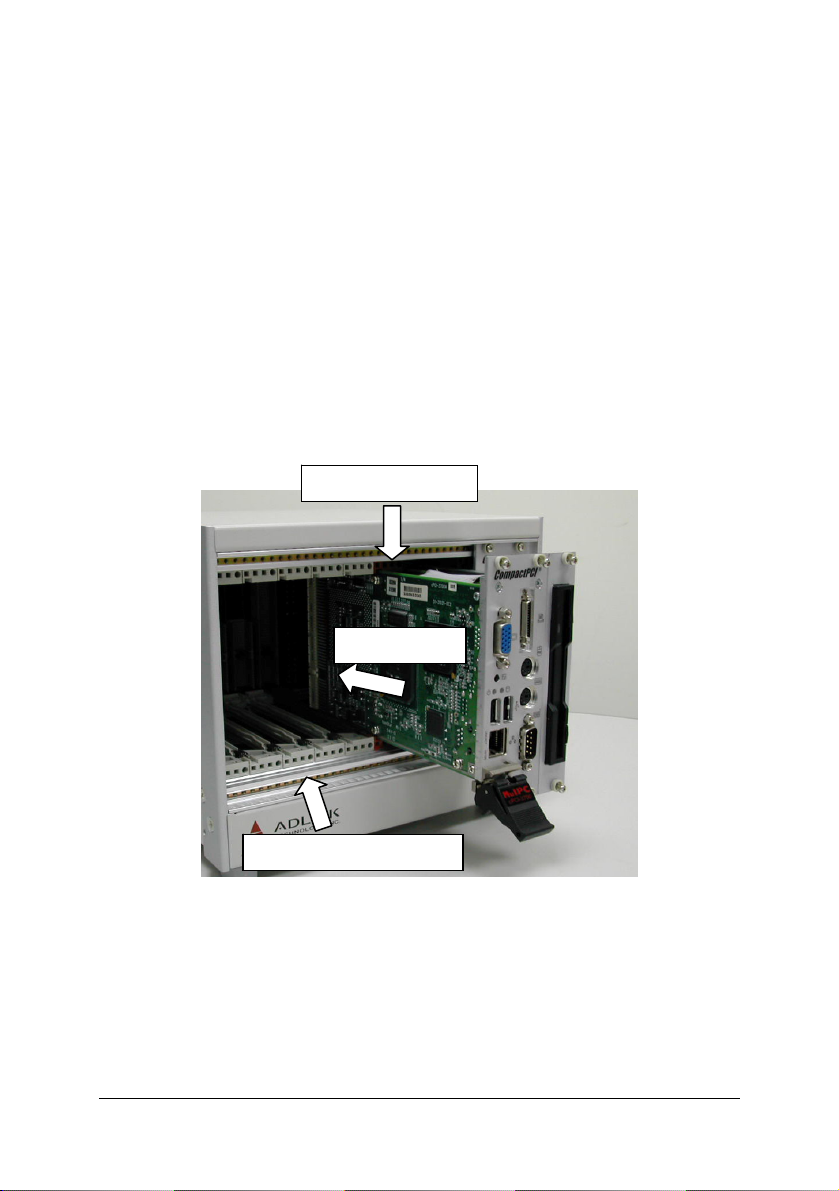
CompactPCI Card Installation/Removal Procedure
1. Place the chassis on a level surface. Remove the blanking plates where
required by undoing the retaining screws at each end. Retain the blanking
plates for possible future use. The system should not be put into use
without blanking plates for all empty slots, otherwise the EMC and cooling
performance will be compromised
2. Hold the SBC module, peripheral card or PSU module vertically. For PSU
modules, make sure that the handle is unlatched (i.e. that it is pulled
downwards) by first pressing on the locking button with your thumb.
3. Carefully insert the module into the desired slot by sliding the edges of the
board into the appropriate card guide rail. Take care to ensure correct
alignment of the card with the chassis during insertion to prevent damage
to the card and/or backplane.
System Card Slot
Insert Module
Peripheral Card Slots
4. Continue inserting the card until the handle engages with the chassis.
5. Pull upwards on the handle for final insertion. For PSU modules, ensure
that the locking button on the handle is fully latched into position. Fasten
the retaining screws at each end of the card (2 for single slot cards, 4 for
double slot cards).
6 • Getting Started
Page 13

y
Locking Button
System Card
Inserted
Full
To remove the module, press the locking button (if necessary), and reverse
steps 1 through 5 above.
Getting Started • 7
Page 14

CompactPCI PSU Installation/Removal Procedure
The installation and removal procedures for a CompactPCI PSU are the
same as those for CompactPCI boards. See the figures below.
PSU Slot
Insert Module
Handle Engages
with Chassis
8 • Getting Started
Fully Latched
Page 15

2.3 Powering Up the System
Set the main power switch in the lower right corner of the rear panel to the off
position ( O ). Set the secondary power switch
front panel
socket on the back of the chassis. The supplied PSU is full range 90-240VAC
and does not require input voltage setting. Insert a system module and any
desired peripheral cards into the appropriate card slots.
To power up the system, set the secondary power switch on the front panel
to the on position (
to the off position ( I ). Connect the supplied power cord to the
II
).
in the lower right corner of the
Getting Started • 9
Page 16

This page intentionally left blank.
Page 17

3 Backplane
In this chapter, we will describe the backplanes for the cPCIS-2501, the cBP3206 is a 3U CompactPCI 32-bit backplane and the cBP-3061 power
backplane.
3.1 cBP-3206 Backplane
Specifications
• Standard CompactPCI height for 3U cPCI cards
• CompactPCI Compliancy
o
PICMG 2.0 CompactPCI core specification R3.0
o
PICMG 2.1 CompactPCI hot swap R2.0
• Dimensions: 100.7 x 128.7 mm
• PCI bus clock: up to 32-bit/33MHz
• System Slot: one R-hand side dual-slot
• Peripheral slots: 5
• Power Connectors: ATX connector x2, DC screw terminals
• V (I/O): 3.3V or 5V selectable, default 5V
• Other connectors: INH#, Reset, PWR_FAL#
Backplane • 11
Page 18

Mechanical Drawing
JP8 - JP10
CN1
6 - P2
6 - P1
cBP-3206 Front View
1 - P2
1 - P1
CN2
12 • Backplane
cBP-3206 RearView
Page 19

Pin Assignment
¾ [1 – P1] System Slot
Pin Z A B C D E F
GND +5V REQ64#
25
GND AD[1] +5V V(I/O)
24
GND +3.3V AD[4] AD[3] +5V AD[2] GND
23
GND AD[7] GND +3.3V AD[6] AD[5] GND
22
GND +3.3V AD[9] AD[8] M66EN C/BE[0]# GND
21
GND AD[12] GND V(I/O)
20
GND +3.3V AD[15] AD[14] GND AD[13] GND
19
GND SERR# GND +3.3V PAR C/BE[1]# GND
18
GND +3.3V IPMB_SCL
17
GND DEVSEL# GND V(I/O)
16
GND +3.3V FRAME# IRDY# BDSEL TRDY# GND
15
12-14 Key
GND AD[18] AD[17] AD[16] GND C/BE[2]# GND
11
GND AD[21] GND +3.3V AD[20] AD[19] GND
10
GND C/BE[3]# IDSEL AD[23] GND AD[22] GND
9
GND AD[26] GND V(I/O)
8
GND AD[30] AD[29] AD[28] GND AD[27] GND
7
GND REQ# GND +3.3V CLK AD[31] GND
6
GND Reserved
5
GND IPMB_PWR HEALTHY# V(I/O)
4
GND INTA# INTB# INTC# +5V INTD# GND
3
GND TCK
2
GND +5V -12V TRST#
1
Reserved PCIRST# GND GNT# GND
+5V TMS
Pin Z A B C D E F
ENUM# +3.3V +5V GND
AD[0] ACK64# GND
AD[11] AD[10] GND
IPMB_SDA GND PERR# GND
STOP# LOCK# GND
AD[25] AD[24] GND
INTP INTS GND
TDO TDI
+12V +5V GND
GND
Backplane • 13
Page 20

¾ [1 – P2] System Slot
Pin Z A B C D E F
22 GND GA4
21 GND CLK6 GND NC NC NC GND
20 GND CLK5 GND NC NC NC GND
19 GND GND GND NC NC NC GND
18 GND NC NC NC NC NC GND
17 GND NC NC PRST# REQ6# GNT6# GND
16 GND NC NC DEG# NC NC GND
15 GND NC NC FAL# REQ5# GNT5# GND
14 GND NC NC NC NC NC GND
13 GND NC NC NC NC NC GND
12 GND NC NC NC NC NC GND
11 GND NC NC NC NC NC GND
10 GND NC NC NC NC NC GND
9 GND NC NC NC NC NC GND
8 GND NC NC NC NC NC GND
7 GND NC NC NC NC NC GND
6 GND NC NC NC NC NC GND
5 GND NC NC NC NC NC GND
4 GND V(I/O) NC NC NC NC GND
3 GND CLK4 GND GNT3# REQ4# GNT4# GND
2 GND CLK2 CLK3 GND GNT2# REQ3# GND
1 GND CLK1 GND REQ1# GNT1# REQ2# GND
Pin Z A B C D E F
GA3 GA2 GA1 GA0 GND
14 • Backplane
Page 21

¾ [2 – P1] – [6 – P1] Peripheral Slot
Pin Z A B C D E F
25 GND +5V REQ64# ENUM# +3.3V +5V GND
24 GND AD[1] +5V V(I/O) AD[0] ACK64# GND
23 GND +3.3V AD[4] AD[3] +5V AD[2] GND
22 GND AD[7] GND +3.3V AD[6] AD[5] GND
21 GND +3.3V AD[9] AD[8] M66EN C/BE[0]# GND
20 GND AD[12] GND V(I/O) AD[11] AD[10] GND
19 GND +3.3V AD[15] AD[14] GND AD[13] GND
18 GND SERR# GND +3.3V PAR C/BE[1]# GND
17 GND +3.3V IPMB_SCL IPMB_SDA GND PERR# GND
16 GND DEVSEL# GND V(I/O) STOP# LOCK# GND
15 GND +3.3V FRAME# IRDY# GND TRDY# GND
12-14 Key
11 GND AD[18] AD[17] AD[16] GND C/BE[2]# GND
10 GND AD[21] GND +3.3V AD[20] AD[19] GND
9 GND C/BE[3]# IDSEL AD[23] GND AD[22] GND
8 GND AD[26] GND V(I/O) AD[25] AD[24] GND
7 GND AD[30] AD[29] AD[28] GND AD[27] GND
6 GND REQ# GND +3.3V CLK AD[31] GND
5 GND NC NC PCIRST# GND GNT# GND
4 GND IPMB_PWR HEALTHY# V(I/O) INTP INTS GND
3 GND INTA# INTB# INTC# +5V INTD# GND
2 GND TCK +5V TMS TDO TDI GND
1 GND +5V -12V TRST# +12V +5V GND
Pin Z A B C D E F
¾ [2 – P2] – [6 – P2] Peripheral Slot
Pin Z A B C D E F
22 GND
1-21 GND NC NC NC NC NC GND
GA4
GA3 GA2 GA1 GA0
GND
Backplane • 15
Page 22

¾ CN1 / CN2 – ATX Power Connector
Pin Signal Pin Signal
1
11
1 +3.3V 11 +3.3V
2 +3.3V 12 -12V
3 GND 13 GND
4 +5V 14 PS_ON_L
5 GND 15 GND
6 +5V 16 GND
7 GND 17 GND
8 POWER
GOOD
9 5V STB 19 +5V
10 +12V 20 +5V
¾ JP8 – connector
Pin # Signal Name
1
1
2
¾ JP9 – connector
Pin # Signal Name
1
1
2
¾ JP10 – connector
Pin # Signal Name
1
1 FAL#
2 GND
18 -5V
INH#
-12V Sense
PRST#
GND
16 • Backplane
Page 23

3.2 cBP-3061 Power Backplane
The cBP-3061 is a PICMG 2.11 CompactPCI 3U 47-pin power backplane for
one power module. It is used by the cPCIS-2631/2642[R].
Specifications
• CompactPCI Compliancy: PICMG 2.11 CompactPCI Power Interface
• Dimensions: 40.64x 128.7 mm
• Power Module Sockets: one
• AC/DC input screw terminal: yes
• DC output (ATX connector): one
• Cascading voltage Sense: Built-in ATX connector
• INH#/FAL#/DEG# Distribution: Built-in ATX connector
Mechanical Drawing
CN4
CN1
CN9
CN7
CN2
CN3
CN6
CN5
CN8
cBP-3061 [R]RearViewcBP-3061[R]Front View
Backplane • 17
Page 24

Pin Assignment
¾ CN1 – Power Sense Connector
1
¾ CN2 – Power Sense Connector
1
¾ CN3 – connector
1
Pin # Signal Name
1
2
3
4
5
V1_Sense
GND_S
V2_Sense
V3_Sense
NC
Pin # Signal Name
1
2
3
4
5
V1_Sense
GND_S
V2_Sense
V3_Sense
NC
Pin # Signal Name
1
2
INHJ
GND
18 • Backplane
Page 25

¾ CN4 – Modular Power 47P Connector
Pin Signal Pin Signal
47
44
42
47 ACL/-DC IN 31 GA2
46 ACN/+DC IN 30 V1 SENSE
45 CGND 29 V1ADJ
44 V3 SHARE 28 GA1
43 IPMB_PWR 27 EN#
42 +FAL# 26 RESERVED
41 V2 SHARE 25 GA0
23
20
21
19
40 IPMB_SDA 24 RTN
39 INH# 23 RESERVED
38 DEG# 22 RTN
37 IPMB_SCL 21 V4
36 V3 SENSE 20 V3
35 V1 SHARE 19 RTN
34 S RTN 13-18 V2
33 V2 SENSE 5-12 RTN
32 V2ADJ 1-4 V1
2
1
¾ CN5 – Current Share Connector
Pin # Signal Name
1
2
3
4
1
5 NC
V1_Share
GND
V2_Share
V3_Share
¾ CN6 – Current Share Connector
Pin # Signal Name
1
1
2
3
4
5
V1_Share
GND
V2_Share
V3_Share
NC
Backplane • 19
Page 26

¾ CN7 –AC/DC in Let Connector
1
¾ CN8 – IPMB Connector
1
¾ CN9 – ATX Power Connector
Pin Signal Pin Signal
1
11
1 +3.3V 11 +3.3V
2 +3.3V 12 -12V
3 GND 13 GND
4 +5V 14 PS_ON_L
5 GND 15 GND
6 +5V 16 GND
7 GND 17 GND
8 POWER
9 5V STB 19 +5V
10 +12V 20 +5V
Pin # Signal Name
1
2
3
ACN/DC+
ACL/DC-
CGND
Pin # Signal Name
1
2
3
4
5
IPMB_SCL
GND
IPMB_SDA
IPMB_PWR
ALERT
18 -5V
GOOD
20 • Backplane
Page 27

4 Cooling System
The cPCIS-2501 is equipped with two bottom access removable fans for
intake to provide an effectively cooled environment. The chassis is equipped
with an air filter that is removable for cleaning and replacement.
4.1 Removing and Replacing the Air Filter
To ensure proper performance, the air filter of cPCIS-2501 should be cleaned
or replaced as necessary.
Air Filter Removal and Replacement Procedure
1. Remove the screws attaching the air inlet grill on the underside of
the chassis as shown below.
remove screws
Cooling System • 21
Page 28

2. Lift the grill and attached fan module out of the chassis. Remove the
remaining two screws attaching the fan module to the grill.
filter element
fan module
3. After cleaning or replacing the filter, place it back in position, secure
the fan module to the inlet grill by replacing the two screws removed
in Step 2, and re-install the grill into the chassis.
22 • Cooling System
Page 29

4.2 Fan Removal and Replacement
To remove the fan module from the chassis, follow the
and Replacement Procedure
behind the backplane as shown below. Disconnect the power cable, and
replace with a functional fan module. Re-insert the connectors behind the
backplane and replace the fan module/air inlet grill assembly.
above. Pull the fan power connectors out from
Air Filter Removal
disconnect cables
Cooling System • 23
Page 30

This page intentionally left blank.
Page 31

5 Power Supply Unit
The cPCIS-2501 is equipped with ADLINK’s cPS-H325/AC CompactPCI power
module.
5.1 CompactPCI: cPS-H325/AC
Features
• 250W 3U X 8HP Eurocard package
• Meets IEC1000-3-2 harmonic correction
• Internal OR-ing diodes for N+1 redundancy
• Hot-swappable
• Third-wire current sharing
• EMI meets EN 55022 / FCC CLASS A
• CE marking compliance
• Fully compliant with PICMG
Specifications
• Operating Temperature Range: 0 °C to 50°C
• Storage Temperature: -40 to +85
• Temperature Coefficient: Typ. ±0.02% /
• Cooling: >20 CFM moving air required to achieve full rated power
• Dimensions: Eurocard 3U X 8HP X 160mm CompactPCI format
• Efficiency: 78-79% typical
• Switching Frequency: 120K Hz
• Safety: IEC60950 Class I
• Circuit Topology: Forward circuit
• Transient Response: Peak transient less than 100mV and recovers
within 2mS after 25% load-change
°C
°C
Power Supply Unit • 25
Page 32

Input Characteristics
• Input Voltage: Typ. 90-264VAC
• Power Factor Correction: Meets Harmonic Correction IEC1000-3-2.
Power Factor typ. 0.95-0.97
• Input Connector: Positronic 47-pin PCIH47M400A1
• Input Frequency: 47-63Hz
• Inrush Current: Less than 30A @ 230VAC
• Input Current: 2.8A @115VAC / 1.4A @230VAC
• Dielectric Withstand: Meets IEC950 regulation
• EMI: Meets EN55022 / FCC Class A
• Hold-up Time: 5mS after power fail signal
• Remote ON/OFF: Available at [INH#] & [EN#] pins
• Power Fail Signal: Available at [FAL#] pin
• Status LED: <Green> means valid input voltage; <Amber> means a
critical fault.
• Thermal Protection (OTP): Installed NTC and thermostat for thermal
sensor at [DEG#] pin
• Power OK: Installed at all outputs
• Leakage Current: Typ. 0.5mA
Output Characteristics
Output Current (A)
Output
Voltage
MIN. MAX. TYP. PEAK.
5V
MAIN +VO1
@ ★ # ≡ ☉
3.3V
AUX. +VO2
▲ @ ★ # ≡ ☉
12V
AUX. +VO3
▲ ≡ # ☉ ★ @
-12V
AUX. –VO4
● ☉ ★ ■ =
26 • Power Supply Unit
2.0 33.0 25.0 –
0 33 18 –
0 5.5 5.5 6
0 1 0.5 1.5
Page 33

Symbol: "★" OVP built-in; "@" Adjustable; "#" Remote sensing;
"≡" 3rd-wire Load Sharing; "=" Droop Current Sharing;
"☉" Installed with Or-ing diode; "▲" Magnetic Amplifier;
"●" Installed with Post-regulator; "■" Common Choke.
Remarks: Peak load sustainable for less than 60sec. with duty cycle <10%.
Max. load is the continuous operating load of each rail. Max. load
of each rail cannot be drawn from all outputs at the same time.
• Over Load Protection: Fully protected against output overload or
short circuit. Typical 120% max. load.
• Over Current Protection: Installed at each rail
• Output Wattage: Typ. 250W continuous.
• Output Connector: Positronic 47-pin PCIH47M400A1.
• Line Regulation: Typ. 0.1%.
• Load Regulation: Typ. ±1–2%.
• Noise & Ripple: Typ. 1% peak to peak or 50mV, whichever is
greater.
• OVP: Built-in at all outputs.
• Adjustability: Available at VO1, 2 & 3.
• Output Trim: Electrical trim available at VO1/VO2 [ADJ #].
• Remote Sensing: Available at VO1, VO2 & VO3.
• Hot-Swap: Available.
• N+1 Redundancy: Installed with internal OR-ing diodes at all outputs
for N+1 redundancy operation.
• Current Sharing: Third-wire current sharing at VO1,2 &3.
• Power OK Signal: Available for all output.
• Over Current Protection: Installed at each rail.
• Overload Protection: Fully protected against output overload or
short circuit. Typical 120% max. load.
Power Supply Unit • 27
Page 34

This page intentionally left blank.
Page 35

Important Safety Instructions
Read and follow all instructions marked on the product and in the
documentation before you operate your system. Retain all safety and
operating instructions for future use.
z Please read these safety instructions carefully.
z Please keep this User‘s Manual for later reference.
z The equipment can be operated at an ambient temperature of 50ºC.
z The equipment should be operated only from the type of power source
indicated on the rating label. Make sure the voltage of the power
source when connect the equipment to the power outlet.
z If your equipment has a voltage selector switch, make sure that the
switch is in the proper position for your area. The voltage selector
switch is set at the factory to the correct voltage.
z For pluggable equipment, that the socket-outlet shall be installed near
the equipment and shall be easily accessible.
z Place the power cord such a way that people can not step on it. Do
not place anything over the power cord.
z If the equipment is not use for long time, disconnect the equipment
from mains to avoid being damaged by transient overvoltage.
z All cautions and warnings on the equipment should be noted.
z Please keep this equipment from humidity.
z Do not use this equipment near water or a heat source.
z Lay this equipment on a reliable surface when install. A drop or fall
could cause injury.
z Never pour any liquid into opening; this could cause fire or electrical
shock.
z Openings in the case are provided for ventilation. Do not block or cover
these openings. Make sure you provide adequate space around the
system for ventilation when you set up your work area. Never insert
objects of any kind into the ventilation openings.
z To avoid electrical shock, always unplug all power cables and modem
cables from the wall outlets before removing covers.
Important Safety Instructions • 29
Page 36

z Lithium Battery provided (real time clock battery)
“CAUTION – Risk of explosion if battery is replaced by an incorrect
type. Dispose of used batteries according to the instructions”
z If one of the following situations arises, get the equipment checked by
a service personnel:
A. The power cord or plug is damaged.
B. Liquid has penetrated into the equipment.
C. The equipment has been exposed to moisture.
D. The equipment has not work well or you can not get it work
according to user‘s manual.
E. The equipment has dropped and damaged.
F. If the equipment has obvious sign of breakage.
30 • Important Safety Instructions
 Loading...