

Page 1

cPCIS-1100 Series
3U Height Subsystems for
CompactPCI Modules
User’s Manual
Manual Rev.: 2.00
Date: September 15, 2014
Part Number: 50-15091-2000
Page 2

Revision History
Revision Release Date Description of Change(s)
2.00 September 15, 2014 Initial release
Copyright 2014 ADLINK Technology, Inc.
All Rights Reserved.
The information in this document is subject to change without prior notice in
order to improve reliability, design and function and does not represent a
commitment on the part of the manufacturer.
In no event will the manufacturer be liable for direct, indirect, special, incidental,
or consequential damages arising out of the use or inability to use the product
or documentation, even if advised of the possibility of such damages.
This document contains proprietary information protected by copyright. All
rights are reserved. No part of this manual may be reproduced by any
mechanical, electronic, or other means in any form without prior written
permission of the manufacturer.
Trademarks
Product names mentioned herein are used for identification purposes only and
may be trademarks and/or registered trademarks of their respective companies.
Page 3

Table of Contents
1 Introduction ....................................................................................1
1.1 Product Definition ......................................................................1
1.2 Mechanical Drawing ..................................................................2
1.3 Configurations............................................................................3
1.4 Customized Systems ................................................................. 3
2 Getting Started ...............................................................................5
2.1 Shipping Contents .....................................................................5
2.2 CompactPCI Board & PSU Installation cPCIS-1100 Series
models with CompactPCI PSU(s) .......................................................
2.3 RTM (Rear Transition Module) Installation................................ 8
2.4 Powering Up the System ...........................................................9
3 Backplane .....................................................................................11
3.1 cBP-3208[R] Backplane...........................................................11
Specifications .....................................................................11
Mechanical Drawing ...........................................................12
Pin Assignment...................................................................14
3.2 cBP-3206[R] Backplane...........................................................18
Specifications .....................................................................18
Mechanical Drawing ...........................................................19
Pin Assignment...................................................................20
3.3 cBP-3061 Power Backplane....................................................24
Specifications .....................................................................24
Mechanical Drawing ...........................................................24
Pin Assignment...................................................................25
3.4 cBP-3062A Power Backplane .................................................28
Specifications .....................................................................28
Mechanical Drawing ...........................................................28
Pin Assignment...................................................................29
5
4 Power Supply Units .....................................................................33
4.1 ATX: Zippy PS2 HG2-6400P ...................................................33
Features .............................................................................33
Specifications .....................................................................33
Input Characteristics........................................................... 34
Output Characteristics........................................................ 34
Table of Contents • iii
Page 4

4.2 CompactPCI: cPS-H325/AC ....................................................35
Features .............................................................................35
Specifications .....................................................................35
Input Characteristics........................................................... 35
Output Characteristics........................................................ 36
4.3 CompactPCI ETT PSU: cPS-P325/AC .................................... 37
Features .............................................................................37
Specifications .....................................................................37
Input Characteristics........................................................... 37
Output Characteristics........................................................ 38
5 Specifications...............................................................................41
5.1 Features...................................................................................41
5.2 Mechanical...............................................................................41
5.3 Environmental ..........................................................................42
Important Safety Instructions ...................................................43
iv • Table of Contents
Page 5
1 Introduction
1.1 Product Definition
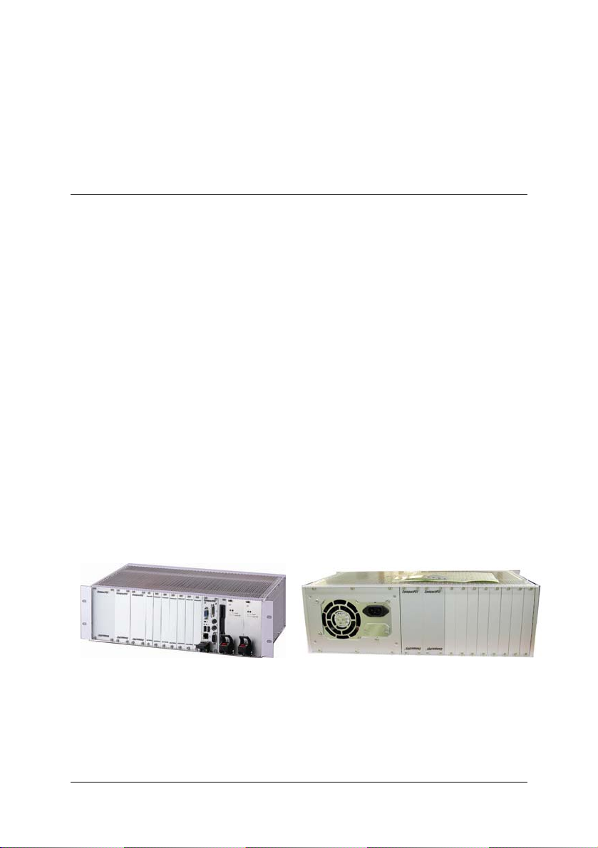
The cPCIS-1100 Series Subsystems are rack mountable, 3U in height, and
designed for 3U CompactPCI cards and modules. They are ideal for
industrial or transport applications where small chassis size with multifunctionality are important, and provide ample power capacity, a hot swap
backplane and easy maintenance. The cPCIS-ET1100 Series' ability to
handle a wide range of temperatures and excellent shock and vibration
characteristics make it suitable for operation in a rigorous environment. The
cPCIS-ET1100 Series allows for custom configuration, giving system
integrators maximum flexibility to build in specialized functionality.
This user’s manual provides unpacking, operating, and maintenance
information for the cPCI-1100 Series 3U CompactPCI subsystems. The
cPCI-1100 Series subsystems are assembled using the following
components:
Components:
Chassis: cPRK-1100
Power Supply: 3U CompactPCI or ATX PS/2 form factor PSU
Backplane: PICMG 2.0 R3.0 Hot Swap compatibility
cPCIS-1100 Series shown (CPU card is not included)
Introduction • 1
Page 6
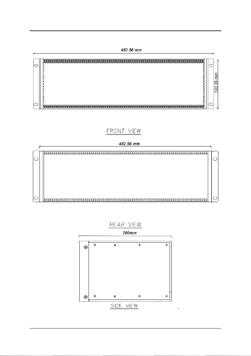
1.2 Mechanical Drawing
2 • Introduction
Page 7

1.3 Configurations
The cPCI-1100 Series comes in the following configurations:
cPCIS-1100A[R] 1 7 400W ATX — 2.0, 2.1
cPCIS-1101[R] 1 7
cPCIS-1102[R] 1 7
cPCIS-1202[R]
(dual system)
cPCIS-ET1101 1 7
cPCIS-ET1102 1 7
*All models are available with rear I/O backplanes for Rear Transition
Modules (RTMs) and are indicated by an “R” suffix on the model name.
System
Slots
1 x 2 5 x 2
Peripheral
Slots
PSU(s) Monitor PICMG
250W
cPCI
250W
cPCI (1+1)
250W
cPCI (1 /
1)
250W ETT
cPCI PSU
250W ETT
2 x cPCI
PSU
— 2.0, 2.1, 2.11
— 2.0, 2.1, 2.11
— 2.0, 2.1, 2.11
— 2.0,2.1 2.11
— 2.0, 2.1, 2.11
1.4 Customized Systems
Sub-systems can also be customized to meet individual needs. To customize
a sub-system please contact an ADLINK dealer. For complete systems,
users must order CPU modules in addition to the sub-system.
Introduction • 3
Page 8

This page intentionally left blank.
4 • Introduction
Page 9

2 Getting Started
In this chapter, we will describe the unpacking procedure of the sub-system
and CompactPCI board and power supply unit (PSU) installation procedures
for cPCIS-1100 Series models with CompactPCI PSU(s) only.
2.1 Shipping Contents
Check the shipping carton for any damage. If the shipping carton and
contents are damaged, please notify the dealer for a replacement. Retain
the shipping carton and packing material for inspection by the dealer. Obtain
authorization before returning any product to ADLINK.
Check that the following items are included in the package. If there are any
missing items, please contact your dealer:
• One cPCIS-1100 Series sub-system
• This User’s Manual
• Power cord (either N. American or European)
2.2 CompactPCI Board & PSU Installation
cPCIS-1100 Series models with CompactPCI PSU(s)
The CompactPCI connectors are rigid and require careful handling when
inserted and removed. Improper handling of cards can easily damage the
backplane.
The PSU slot also has an obvious indicator such as a green card guide rail in a
standard CompactPCI chassis (see photos below, chassis in photos are for
reference only).
Getting Started • 5
Page 10
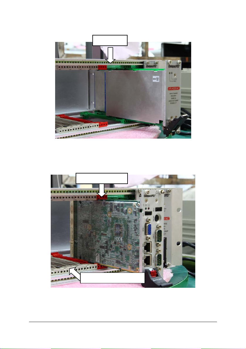
PSU Slot
System slots have obvious indicators (e.g. red card guide rail, triangle mark
enclosing the slot number on the backplane, etc.) System cards can only be
installed in a system slot. Do not insert a system card into any other slot, or
insert any peripheral card into system slot.
System Card Slot
Peripheral Card Slots
The handle on CompactPCI cards and PSUs ensures simple and safe
installation and removal. Please follow the procedures below to install a
CompactPCI module into a cPCIS-1100 Series chassis with CompactPCI
PSU(s):
6 • Getting Started
Page 11

CompactPCI Card Installation/Removal Procedure
1. Place the sub-system on a level surface or rackmount it. Remove the
blanking plates where required by undoing the retaining screws at each
end. Retain the blanking plates for possible future use. The system should
not be put into use without blanking plates for all empty slots, otherwise the
EMC will be compromised
2. Hold the SBC module, peripheral card or PSU module vertically. For PSU
modules, make sure that the handle is unlatched (i.e. that it is pulled
downwards) by first pressing on the locking button with your thumb.
Insert Module
Unlatched
Locking Button
3. Carefully insert the module into the desired slot by sliding the edges of the
board into the appropriate card guide rail. Take care to ensure correct
alignment of the card with the chassis during insertion to prevent damage
to the card and/or backplane.
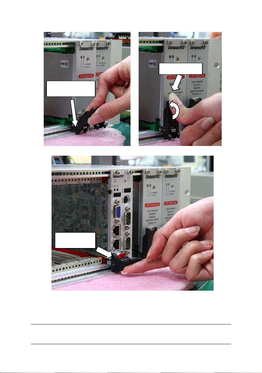
4. Continue inserting the card until the handle engages with the chassis.
5. Pull upwards on the handle for final insertion. For PSU modules, ensure
that the locking button on the handle is fully latched into position.
Getting Started • 7
Page 12
y
Fully Latched
Handle Engages
with Chassis
System Card
Full
Inserted
To remove the module, press the release button (if necessary), and reverse
steps 1 through 5 above.
2.3 RTM (Rear Transition Module) Installation
8 • Getting Started
Page 13

The installation and removal procedures for a RTM are the same as those for
CompactPCI boards. Because they are shorter than front boards, pay careful
attention when inserting or removing RTMs. Only models with an “R” at the end
of the model number support RTMs.
Note: We strongly recommended the use of RTMs with AB type connectors
to prevent damaging the backplane during RTM installation.
2.4 Powering Up the System
Connect the supplied power cord to the socket on the back of the chassis. All
supplied PSUs are full range 90-240VAC and do not require input voltage
setting.
Getting Started • 9
Page 14

This page intentionally left blank.
10 • Getting Started
Page 15
3 Backplane
In this chapter, we will describe the backplanes for the cPCIS-1100 Series
subsystems. The following table specifies the backplane(s) that correspond
to each model.
backplane slots
cPCIS-1100A[R] cBP-3208[R] 8 —
cPCIS-1101[R] cBP-3208[R] 8 cBP-3061
cPCIS-1102[R] cBP-3208[R] 8 cBP-3062A
cPCIS-1202[R]
(dual system)
cPCIS-ET1101 cBP-3208 8 cBP-3061
cPCIS-ET1102 cBP-3208 8 cBP-3062A
cBP-3206[R]
(x2)
6
(x2)
power
backplane
cBP-3061
(x2)
3.1 cBP-3208[R] Backplane
The cBP-3208[R] is a 3U CompactPCI 32-bit backplane with optional rear I/O
(designated by an “R” suffix). It is used by the cPCIS-1100A / cPCIS-1101 /
cPCIS-1102 / cPCIS-ET1101 / cPCIS-ET1102.
Specifications
Standard CompactPCI height for 3U cPCI cards
CompactPCI Compliancy
PICMG 2.0 CompactPCI core specification R3.0
PICMG 2.1 CompactPCI hot swap R2.0
Dimensions: 141.3 x 128.7 mm
PCI bus clock: up to 32-bit/33MHz
System Slot: one R-hand side dual-slot
System Slot Rear I/O: P2 rear I/O with AB-type shroud
Backplane • 11
Page 16

Peripheral slots: 7
Peripheral Slots
Rear I/O:
P2 rear I/O with AB-type shroud (optional)
Power Connectors: ATX connector x2, DC screw terminals
V (I/O): 3.3V or 5V selectable, default 5V
Other connectors: INH#, Reset, PWR_FAL#
Mechanical Drawing
8 - P2
8 - P1
cBP-3208[R]Front View
1 - P2
1 - P1
12 • Backplane
Page 17

1 - P2
Optional Rear I/O: 2 - P2 to 8 - P2
cBP-3208[R] Rear View
Backplane • 13
Page 18

Pin Assignment
¾ [1 – P1] System Slot
Pin Z A B C D E F
GND +5V REQ64#
25
GND AD[1] +5V V(I/O)
24
GND +3.3V AD[4] AD[3] +5V AD[2] GND
23
GND AD[7] GND +3.3V AD[6] AD[5] GND
22
GND +3.3V AD[9] AD[8] M66EN C/BE[0]# GND
21
GND AD[12] GND V(I/O)
20
GND +3.3V AD[15] AD[14] GND AD[13] GND
19
GND SERR# GND +3.3V PAR C/BE[1]# GND
18
GND +3.3V IPMB_SCL
17
GND DEVSEL# GND V(I/O)
16
GND +3.3V FRAME# IRDY# BDSEL TRDY# GND
15
12-14 Key
GND AD[18] AD[17] AD[16] GND C/BE[2]# GND
11
GND AD[21] GND +3.3V AD[20] AD[19] GND
10
GND C/BE[3]# IDSEL AD[23] GND AD[22] GND
9
GND AD[26] GND V(I/O)
8
GND AD[30] AD[29] AD[28] GND AD[27] GND
7
GND REQ# GND +3.3V CLK AD[31] GND
6
GND Reserved
5
GND IPMB_PWR HEALTHY# V(I/O)
4
GND INTA# INTB# INTC# +5V INTD# GND
3
GND TCK
2
GND +5V -12V TRST#
1
Reserved PCIRST# GND GNT# GND
+5V TMS
Pin Z A B C D E F
ENUM# +3.3V +5V GND
AD[0] ACK64# GND
AD[11] AD[10] GND
IPMB_SDA GND PERR# GND
STOP# LOCK# GND
AD[25] AD[24] GND
INTP INTS GND
TDO TDI
+12V +5V GND
GND
14 • Backplane
Page 19

¾ [1 – P2] System Slot
Pin Z A B C D E F
22 GND GA4
21 GND CLK6 GND NC NC NC GND
20 GND CLK5 GND NC NC NC GND
19 GND GND GND NC NC NC GND
18 GND NC NC NC NC NC GND
17 GND NC NC PRST# REQ6# GNT6# GND
16 GND NC NC DEG# NC NC GND
15 GND NC NC FAL# REQ5# GNT5# GND
14 GND NC NC NC NC NC GND
13 GND NC NC NC NC NC GND
12 GND NC NC NC NC NC GND
11 GND NC NC NC NC NC GND
10 GND NC NC NC NC NC GND
9 GND NC NC NC NC NC GND
8 GND NC NC NC NC NC GND
7 GND NC NC NC NC NC GND
6 GND NC NC NC NC NC GND
5 GND NC NC NC NC NC GND
4 GND V(I/O) NC NC NC NC GND
3 GND CLK4 GND GNT3# REQ4# GNT4# GND
2 GND CLK2 CLK3 GND GNT2# REQ3# GND
1 GND CLK1 GND REQ1# GNT1# REQ2# GND
Pin Z A B C D E F
GA3 GA2 GA1 GA0 GND
Backplane • 15
Page 20

¾ [2 – P1] / [8 – P1] Peripheral Slot
Pin Z A B C D E F
25 GND +5V REQ64# ENUM# +3.3V +5V GND
24 GND AD[1] +5V V(I/O) AD[0] ACK64# GND
23 GND +3.3V AD[4] AD[3] +5V AD[2] GND
22 GND AD[7] GND +3.3V AD[6] AD[5] GND
21 GND +3.3V AD[9] AD[8] M66EN C/BE[0]# GND
20 GND AD[12] GND V(I/O) AD[11] AD[10] GND
19 GND +3.3V AD[15] AD[14] GND AD[13] GND
18 GND SERR# GND +3.3V PAR C/BE[1]# GND
17 GND +3.3V IPMB_SCL IPMB_SDA GND PERR# GND
16 GND DEVSEL# GND V(I/O) STOP# LOCK# GND
15 GND +3.3V FRAME# IRDY# GND TRDY# GND
12-14 Key
11 GND AD[18] AD[17] AD[16] GND C/BE[2]# GND
10 GND AD[21] GND +3.3V AD[20] AD[19] GND
9 GND C/BE[3]# IDSEL AD[23] GND AD[22] GND
8 GND AD[26] GND V(I/O) AD[25] AD[24] GND
7 GND AD[30] AD[29] AD[28] GND AD[27] GND
6 GND REQ# GND +3.3V CLK AD[31] GND
5 GND NC NC PCIRST# GND GNT# GND
4 GND IPMB_PWR HEALTHY# V(I/O) INTP INTS GND
3 GND INTA# INTB# INTC# +5V INTD# GND
2 GND TCK +5V TMS TDO TDI GND
1 GND +5V -12V TRST# +12V +5V GND
Pin Z A B C D E F
¾ [2 – P2] / [8 – P2] Peripheral Slot
Pin Z A B C D E F
22 GND
1-21 GND NC NC NC NC NC GND
GA4
GA3 GA2 GA1 GA0
GND
16 • Backplane
Page 21

¾ CN1 / CN2 – ATX Power Connector
1
11
Pin Signal Pin Signal
1 +3.3V 11 +3.3V
2 +3.3V 12 -12V
3 GND 13 GND
4 +5V 14 PS_ON_L
5 GND 15 GND
6 +5V 16 GND
7 GND 17 GND
8 POWER
9 5V STB 19 +5V
10 +12V 20 +5V
¾ JP7 – connector
Pin # Signal Name
1
1
2
¾ JP8 – connector
Pin # Signal Name
1
1
2
¾ JP9 – connector
Pin # Signal Name
1
1 PRST#
2 GND
¾ JP10 – connector
Pin # Signal Name
1
1 FAL#
2 GND
¾ JP1- V (I/O), default: +5V
1
Pin # Signal Name Pin # Signal Name
1 +12V 2 GND
3 -12V 4 GND
5 +3.3V 6 GND
7 +5V 8 GND
8
18 -5V
GOOD
+12V
-12V Sense
INH#
GND
Backplane • 17
Page 22

3.2 cBP-3206[R] Backplane
The cBP-3206[R] is a 3U CompactPCI 32-bit backplane with optional rear I/O
(designated by an “R” suffix). The cPCIS-1202[R] uses two of these backplanes.
Specifications
Standard CompactPCI height for 3U cPCI cards
CompactPCI Compliancy
PICMG 2.0 CompactPCI core specification R3.0
PICMG 2.1 CompactPCI hot swap R2.0
Dimensions: 100.7 x 128.7 mm
PCI bus clock: up to 32-bit/33MHz
System Slot: one R-hand side dual-slot
System Slot Rear I/O: P2 rear I/O with AB-type shroud
Peripheral slots: 5
Peripheral Slots
Power Connectors: ATX connector x2, DC screw terminals
V (I/O): 3.3V or 5V selectable, default 5V
Other connectors: INH#, Reset, PWR_FAL#
Rear I/O:
P2 rear I/O with AB-type shroud (optional)
18 • Backplane
Page 23

Mechanical Drawing
[R]
6 - P2
6 - P1
1 - P2
1 - P1
JP8 - JP10
CN1
cBP-3206
1 - P2
Front View
Opt. Rear I/O:
2 - P2 to 6 - P2
CN2
cBP-3206[R]Rear View
Backplane • 19
Page 24

Pin Assignment
¾ [1 – P1] System Slot
Pin Z A B C D E F
GND +5V REQ64#
25
GND AD[1] +5V V(I/O)
24
GND +3.3V AD[4] AD[3] +5V AD[2] GND
23
GND AD[7] GND +3.3V AD[6] AD[5] GND
22
GND +3.3V AD[9] AD[8] M66EN C/BE[0]# GND
21
GND AD[12] GND V(I/O)
20
GND +3.3V AD[15] AD[14] GND AD[13] GND
19
GND SERR# GND +3.3V PAR C/BE[1]# GND
18
GND +3.3V IPMB_SCL
17
GND DEVSEL# GND V(I/O)
16
GND +3.3V FRAME# IRDY# BDSEL TRDY# GND
15
12-14 Key
GND AD[18] AD[17] AD[16] GND C/BE[2]# GND
11
GND AD[21] GND +3.3V AD[20] AD[19] GND
10
GND C/BE[3]# IDSEL AD[23] GND AD[22] GND
9
GND AD[26] GND V(I/O)
8
GND AD[30] AD[29] AD[28] GND AD[27] GND
7
GND REQ# GND +3.3V CLK AD[31] GND
6
GND Reserved
5
GND IPMB_PWR HEALTHY# V(I/O)
4
GND INTA# INTB# INTC# +5V INTD# GND
3
GND TCK
2
GND +5V -12V TRST#
1
Reserved PCIRST# GND GNT# GND
+5V TMS
Pin Z A B C D E F
ENUM# +3.3V +5V GND
AD[0] ACK64# GND
AD[11] AD[10] GND
IPMB_SDA GND PERR# GND
STOP# LOCK# GND
AD[25] AD[24] GND
INTP INTS GND
TDO TDI
+12V +5V GND
GND
20 • Backplane
Page 25

¾ [1 – P2] System Slot
Pin Z A B C D E F
22 GND GA4
21 GND CLK6 GND NC NC NC GND
20 GND CLK5 GND NC NC NC GND
19 GND GND GND NC NC NC GND
18 GND NC NC NC NC NC GND
17 GND NC NC PRST# REQ6# GNT6# GND
16 GND NC NC DEG# NC NC GND
15 GND NC NC FAL# REQ5# GNT5# GND
14 GND NC NC NC NC NC GND
13 GND NC NC NC NC NC GND
12 GND NC NC NC NC NC GND
11 GND NC NC NC NC NC GND
10 GND NC NC NC NC NC GND
9 GND NC NC NC NC NC GND
8 GND NC NC NC NC NC GND
7 GND NC NC NC NC NC GND
6 GND NC NC NC NC NC GND
5 GND NC NC NC NC NC GND
4 GND V(I/O) NC NC NC NC GND
3 GND CLK4 GND GNT3# REQ4# GNT4# GND
2 GND CLK2 CLK3 GND GNT2# REQ3# GND
1 GND CLK1 GND REQ1# GNT1# REQ2# GND
Pin Z A B C D E F
GA3 GA2 GA1 GA0 GND
Backplane • 21
Page 26

¾ [2 – P1] – [6 – P1] Peripheral Slot
Pin Z A B C D E F
25 GND +5V REQ64# ENUM# +3.3V +5V GND
24 GND AD[1] +5V V(I/O) AD[0] ACK64# GND
23 GND +3.3V AD[4] AD[3] +5V AD[2] GND
22 GND AD[7] GND +3.3V AD[6] AD[5] GND
21 GND +3.3V AD[9] AD[8] M66EN C/BE[0]# GND
20 GND AD[12] GND V(I/O) AD[11] AD[10] GND
19 GND +3.3V AD[15] AD[14] GND AD[13] GND
18 GND SERR# GND +3.3V PAR C/BE[1]# GND
17 GND +3.3V IPMB_SCL IPMB_SDA GND PERR# GND
16 GND DEVSEL# GND V(I/O) STOP# LOCK# GND
15 GND +3.3V FRAME# IRDY# GND TRDY# GND
12-14 Key
11 GND AD[18] AD[17] AD[16] GND C/BE[2]# GND
10 GND AD[21] GND +3.3V AD[20] AD[19] GND
9 GND C/BE[3]# IDSEL AD[23] GND AD[22] GND
8 GND AD[26] GND V(I/O) AD[25] AD[24] GND
7 GND AD[30] AD[29] AD[28] GND AD[27] GND
6 GND REQ# GND +3.3V CLK AD[31] GND
5 GND NC NC PCIRST# GND GNT# GND
4 GND IPMB_PWR HEALTHY# V(I/O) INTP INTS GND
3 GND INTA# INTB# INTC# +5V INTD# GND
2 GND TCK +5V TMS TDO TDI GND
1 GND +5V -12V TRST# +12V +5V GND
Pin Z A B C D E F
¾ [2 – P2] – [6 – P2] Peripheral Slot
Pin Z A B C D E F
22 GND
1-21 GND NC NC NC NC NC GND
GA4
GA3 GA2 GA1 GA0
GND
22 • Backplane
Page 27

¾ CN1 / CN2 – ATX Power Connector
Pin Signal Pin Signal
1
11
1 +3.3V 11 +3.3V
2 +3.3V 12 -12V
3 GND 13 GND
4 +5V 14 PS_ON_L
5 GND 15 GND
6 +5V 16 GND
7 GND 17 GND
8 POWER
GOOD
9 5V STB 19 +5V
10 +12V 20 +5V
¾ JP8 – connector
Pin # Signal Name
1
1
2
¾ JP9 – connector
Pin # Signal Name
1
1
2
¾ JP10 – connector
Pin # Signal Name
1
1 FAL#
2 GND
18 -5V
INH#
-12V Sense
PRST#
GND
Backplane • 23
Page 28

3.3 cBP-3061 Power Backplane
The cBP-3061 is a PICMG 2.11 CompactPCI 3U 47-pin power backplane for
one power module. It is used by the cPCIS-11011/cPCIS-1202[R]/cPCISET1101/cPCIS-1202.
Specifications
CompactPCI Compliancy: PICMG 2.11 CompactPCI Power Interface
Dimensions: 39.64x 128.7 mm
Power Module Sockets: one
AC/DC input screw terminal: yes
DC output (ATX connector): one
Cascading voltage Sense: Built-in ATX connector
INH#/FAL#/DEG# Distribution: Built-in ATX connector
Mechanical Drawing
24 • Backplane
CN4
CN1
CN9
CN7
CN2
CN3
CN6
CN5
CN8
cBP-3061 [R]RearViewcBP-3061[R]Front View
Page 29

Pin Assignment
¾ CN1 – Power Sense Connector
1
¾ CN2 – Power Sense Connector
1
¾ CN3 – connector
1
Pin # Signal Name
1
2
3
4
5
V1_Sense
GND_S
V2_Sense
V3_Sense
NC
Pin # Signal Name
1
2
3
4
5
V1_Sense
GND_S
V2_Sense
V3_Sense
NC
Pin # Signal Name
1
2
INHJ
GND
Backplane • 25
Page 30

¾ CN4 – Modular Power 47P Connector
Pin Signal Pin Signal
47
44
23
20
2
42
21
19
¾ CN5 – Current Share Connector
1
¾ CN6 – Current Share Connector
1
47 ACL/-DC IN 31 GA2
46 ACN/+DC IN 30 V1 SENSE
45 CGND 29 V1ADJ
44 V3 SHARE 28 GA1
43 IPMB_PWR 27 EN#
42 +FAL# 26 RESERVED
41 V2 SHARE 25 GA0
40 IPMB_SDA 24 RTN
39 INH# 23 RESERVED
38 DEG# 22 RTN
37 IPMB_SCL 21 V4
36 V3 SENSE 20 V3
35 V1 SHARE 19 RTN
34 S RTN 13-18 V2
33 V2 SENSE 5-12 RTN
32 V2ADJ 1-4 V1
1
Pin # Signal Name
1
2
3
4
5
Pin # Signal Name
1
2
3
4
5
V1_Share
GND
V2_Share
V3_Share
NC
V1_Share
GND
V2_Share
V3_Share
NC
26 • Backplane
Page 31

¾ CN7 –AC/DC in Let Connector
1
¾ CN8 – IPMB Connector
1
¾ CN9 – ATX Power Connector
Pin Signal Pin Signal
1
11
1 +3.3V 11 +3.3V
2 +3.3V 12 -12V
3 GND 13 GND
4 +5V 14 PS_ON_L
5 GND 15 GND
6 +5V 16 GND
7 GND 17 GND
8 POWER
9 5V STB 19 +5V
10 +12V 20 +5V
Pin # Signal Name
1
2
3
ACN/DC+
ACL/DC-
CGND
Pin # Signal Name
1
2
3
4
5
IPMB_SCL
GND
IPMB_SDA
IPMB_PWR
ALERT
18 -5V
GOOD
Backplane • 27
Page 32

3.4 cBP-3062A Power Backplane
The cBP-3062A is a PICMG 2.11 CompactPCI 3U 47-pin power backplane
for two power modules. It is used by the cPCIS-1102[R]/cPCIS-ET1102.
Specifications
CompactPCI Compliancy: PICMG 2.11 CompactPCI Power Interface
Dimensions: 80.28 x 128.7 mm
Power Module Sockets: two
AC/DC input screw terminal: yes
DC output (ATX connector): two
Cascading Current Sharing: yes
Cascading Voltage Sense: Built-in ATX connector
INH#/FAL#/DEG# Distribution: Selectable common INH#/FAL#/DEG# or
separated INH# for each power module, dedicated connector
PICMG 2.0 IPMB Socket: yes
Mechanical Drawing
CN3
CN1
28 • Backplane
CN2
CN8
CN10 CN9
cBP-3062[R]RearViewcBP-3062[R]Front View
CN5
CN7
CN4
Page 33

Pin Assignment
¾ CN1 / CN2 – Modular Power 47P Connector
Pin Signal Pin Signal
47
44
23
20
2
¾ CN3 –AC/DC in Let Connector
1
¾ CN4 – Power Sense Connector
1
47 ACL/-DC IN 31 GA2
46 ACN/+DC IN 30 V1 SENSE
45 CGND 29 V1ADJ
44 V3 SHARE 28 GA1
4
43 IPMB_PWR 27 EN#
2
42 +FAL# 26 RESERVED
41 V2 SHARE 25 GA0
40 IPMB_SDA 24 RTN
21
39 INH# 23 RESERVED
19
38 DEG# 22 RTN
37 IPMB_SCL 21 V4
36 V3 SENSE 20 V3
35 V1 SHARE 19 RTN
34 S RTN 13-18 V2
33 V2 SENSE 5-12 RTN
32 V2ADJ 1-4 V1
1
Pin # Signal Name
1
2
ACN/DC+
ACL/DC-
3
Pin # Signal Name
1
2
3
4
V1_Sense
GND_S
V2_Sense
V3_Sense
5
CGND
NC
Backplane • 29
Page 34

¾ CN5 – Power Sense Connector
Pin # Signal Name
1
¾ CN6 –Connector
Pin # Signal Name
1
¾ CN7 – Current Share Connector
Pin # Signal Name
1
¾ CN8 – Current Share Connector
Pin # Signal Name
1
1
2
3
4
5
V1_Sense
GND_S
V2_Sense
V3_Sense
NC
1
2
3
4
5
IPMB_SCL
GND
IPMB_DA
IPMB_PWR
ALERT
1
2
3
4
5
V1CS
GND_S
V2 CS
V3 CS
NC
1
2
3
4
5
V1 CS
GND_S
V2 CS
V3 CS
NC
30 • Backplane
Page 35

¾ CN9 / CN10 – ATX Power Connector
Pin Signal Pin Signal
1
11
1 +3.3V 11 +3.3V
2 +3.3V 12 -12V
3 GND 13 GND
4 +5V 14 PS_ON_L
5 GND 15 GND
6 +5V 16 GND
7 GND 17 GND
8 POWER
GOOD
9 5V STB 19 +5V
10 +12V 20 +5V
¾ JP1 – connector
Pin # Signal Name
1
1
2
¾ JP2 – connector
Pin # Signal Name
1
1
2
¾ JP3 – connector
1
Pin # Signal Name
1
2
3
4
5
8
6
7
8
¾ JP4 – connector
Pin # Signal Name
1
1
2
18 -5V
INH#2
GND
INH#1
GND
DEG#1
FAL#1
RSV23A
RSV26A
DEG#2
FAL#2
RSV23B
RSV26B
INH#
GND
Backplane • 31
Page 36

This page intentionally left blank.
32 • Backplane
Page 37

4 Power Supply Units
The cPCIS-1100 Series subsystems are equipped with either the Zippy
Technology Corp. PS2 HG2-6400P industrial grade ATX power supply,
ADLINK’s cPS-H325/AC CompactPCI power module or ADLINK’s
cPS-P325/AC wide range temperature operating CompactPCI power module
(see Section 1.3 Configurations).
4.1 ATX: Zippy PS2 HG2-6400P
Features
• Active PFC (full range)
• 12V Max. Current : 30A
• Noise & Thermal Control
Specifications
• Operating Temperature Range: -10°C ~ +45°C
• Cooling: one 80mm DC fan
• Active Power Factor Correction meets IEC-1000-3-2 CLASS D
• Dimensions: 140.00x150.00x86.00 (mm)
• Hold Up Time: 16 ms minimum at full load & normal input voltage
• Dielectric Withstand: input / output 1500 VAC for 1 second
input to frame ground 1500 VAC for 1 second
• Efficiency: 70% typical at 115V, full load.
• Power Good Signal: on delay 100 ms to 500 ms, off delay 1 ms
• Over Load Protection: 130 +/- 20%
• Over Voltage Protection:
5V → 5.7V – 6.5V; 3.3V → 3.9 – 4.3V; 12V → 13.6 – 15V
• Short Circuit Protection: +5V, -5V, +12V, -12V, +3.3V
• EMI Noise Filter: FCC CLASS B, CISPR22 CLASS B
• Safety: UL 60950, CSA 22.2 NO/ 60950, TUV EN-60950& CCC.
• MTBF: 135,268 hrs
Power Supply Unit • 33
Page 38

Input Characteristics
• Voltage: 90 – 240 VAC Full Range
• Frequency : 47 ~ 63 HZ
• Input Current: 8.0 A ( RMS ) FOR 115 VAC
4.0 A ( RMS ) FOR 230 VAC
• Inrush Current: 65A MAX. FOR 115 VAC
125A MAX. FOR 230 VAC
Output Characteristics
Output Current(A) Regulation Output
Output
Voltage
5V 3 35 – ± 5% ± 1% 50mV
12V 2 30 – +7 – -5% ± 1% 120mV
-5V 0 0.5 – ± 5% ± 1% 150mV
-12V 0 0.8 – ± 5% ± 1% 150mV
3.3V 1 28 – ± 5% ± 1% 50mV
MIN. MAX. PEAK LOAD LINE
Ripple&
Noise
Max[P-P]
+5VSB 0.1 2 – ± 5% ± 1% 50mV
Note: The output current of 5V & 3.3V must not exceed 45A.
34 • Power Supply Unit
Page 39

4.2 CompactPCI: cPS-H325/AC
Features
• 250W 3U x 8HP Eurocard package
• Meets IEC1000-3-2 harmonic correction
• Internal OR-ing diodes for N+1 redundancy
• Hot-swappable
• Third-wire current sharing
• EMI meets EN 55022 / FCC CLASS A
• CE marking compliance
• Fully compliant with PICMG
Specifications
• Operating Temperature Range: 0 °Cto 50°C
• Storage Temperature: -40 to +85
• Temperature Coefficient: Typ. ±0.02% /
°C
°C
• Cooling: >20 CFM moving air required to achieve full rated power
• Dimensions: Eurocard 3U X 8HP X 160mm CompactPCI format
• Efficiency: 78-79% typical
• Switching Frequency: 120K Hz
• Safety: IEC60950 Class I
• Circuit Topology: Forward circuit
• Transient Response: Peak transient less than 100mV and recovers
within 2mS after 25% load-change
Input Characteristics
• Input Voltage: Typ. 90-264VAC
• Power Factor Correction: Meets Harmonic Correction IEC1000-3-2.
Power Factor typ. 0.95-0.97
• Input Connector: Positronic 47-pin PCIH47M400A1
• Input Frequency: 47-63Hz
• Inrush Current: Less than 30A @ 230VAC
• Input Current: 2.8A @115VAC / 1.4A @230VAC
Power Supply Unit • 35
Page 40

• Dielectric Withstand: Meets IEC950 regulation
• EMI: Meets EN55022 / FCC Class A
• Hold-up Time: 5mS after power fail signal
• Remote ON/OFF: Available at [INH#] & [EN#] pins
• Power Fail Signal: Available at [FAL#] pin
• Status LED: <Green> means valid input voltage; <Amber> means a
critical fault.
• Thermal Protection (OTP): Installed NTC and thermostat for thermal
sensor at [DEG#] pin
• Power OK: Installed at all outputs
• Leakage Current: Typ. 0.5mA
Output Characteristics
Output Current (A)
Output
Voltage
5V
MAIN +VO1
@ # ≡
3.3V
AUX. +VO2
▲ @ # ≡
12V
AUX. +VO3
▲ ≡ # @
-12V
AUX. –VO4
● ■ =
Symbol: "" OVP built-in; "@" Adjustable; "#" Remote sensing;
"≡" 3rd-wire Load Sharing; "=" Droop Current Sharing;
"" Installed with Or-ing diode; "▲" Magnetic Amplifier;
"●" Installed with Post-regulator; "■" Common Choke.
Remarks: Peak load sustainable for less than 60sec. with duty cycle <10%.
Max. load is the continuous operating load of each rail. Max. load
of each rail cannot be drawn from all outputs at the same time.
MIN. MAX. TYP. PEAK.
2.0 33.0 25.0 –
0 33 18 –
0 5.5 5.5 6
0 1 0.5 1.5
36 • Power Supply Unit
Page 41

4.3 CompactPCI ETT PSU: cPS-P325/AC
Features
• 250W 3U x 8HP Eurocard package
• Meets EN 61000-3-2 active power factor correction
• Internal OR-ing diodes for N+1 redundancy
• Hot-swappable
• Active current sharing
• EMI meets EN 55022 / FCC CLASS A
• CE marking compliance
• Fully compliant with PICMG
Specifications
• Operating Temperature Range: -25°Cto +50°C
• Storage Temperature: -40 to +85
• Temperature Coefficient: Typ. ±0.3% /
°C
°C
• Cooling: > 400 LFM moving air required to achieve full rated power
• Dimensions: Eurocard 3U x 8HP x 160mm CompactPCI format
• Efficiency: 81.5-82.6% typical
• Switching Frequency: 135K Hz
• Safety: IEC60950-1,CSA60950-1 & China CCC
• Circuit Topology: forward circuit
Input Characteristics
• Input Voltage: Typ. 90-264VAC
• Power Factor Correction: meets Harmonic Correction
• Input Connector: CompactPCI 47-pin power connector
• Input Frequency: 47-63Hz
• Inrush Current: ess than 15A@240VAC
• Input Current: 3.6A@230VAC/ 4A@260VAC
• EMI: Meets EN55022 / FCC Class A
• Hold-up Time: 20mS after power fail signal
• Remote ON/OFF: Available at [INH#] & [EN#] pins
EN 61000-3-2
Power Supply Unit • 37
Page 42

• Power Fail Signal: available at [FAL#] pin
• Status LED: <green> means valid input voltage; <amber> means a
critical fault.
• Thermal Protection (OTP): Installed NTC and thermostat for thermal
sensor at [DEG#] pin
• Power OK: Installed at all outputs
• Leakage Current: 1.18mA at 254Vac/60Hz
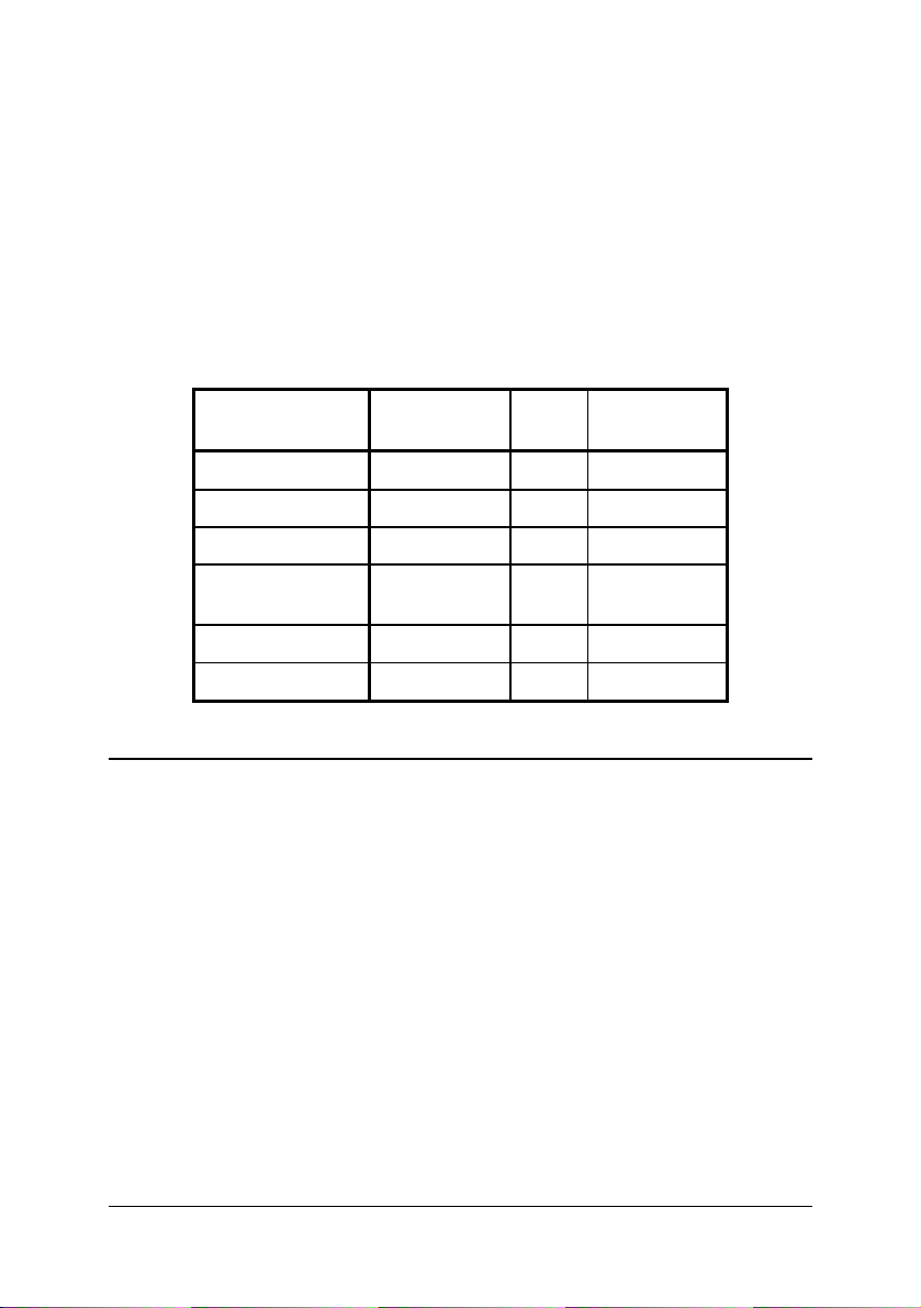
Output Characteristics
Output Current (A)
Output
Voltage
Min. Max. Typ. Peak.
5V
3.3V
12V
-12V
Over Load Protection: fully protected against output overload or short circuit,
typical 120% max. load
Over Current Protection: installed at each rail
o Output Wattage: Typ. 250W continuous.
o Output Connector: CompactPCI 47-pin power connector.
o Line Regulation: Max. ±10mV
o Load Regulation: 3.3V & 5V: ± 10mV, +12V: ± 30mV & -12V: -380
mV.
o Noise & Ripple: 60 mV@5V and 3.3V output; 120mV@.± 12V
output.
o OVP: Built-in at all outputs.
o Adjustability: Available at VO1, 2 & 3.
o Output Trim: Electrical trim available at VO1/VO2 [ADJ #].
o Remote Sensing: Available at VO1, VO2 & VO3.
o Hot-Swap: Available.
o N+1 Redundancy: Installed with internal OR-ing diodes at all outputs
for N+1 redundancy operation.
o Current Sharing: Third-wire current sharing at VO1,2 &3.
o Power OK Signal: Available for all output.
0 40.0 25.0 –
0 40 20 –
0 5.5 4 –
0 2 1 –
38 • Power Supply Unit
Page 43
o Over Current Protection: Installed at each rail.
o Overload Protection: Fully protected against output overload or
short circuit. Typical 120% max. load.
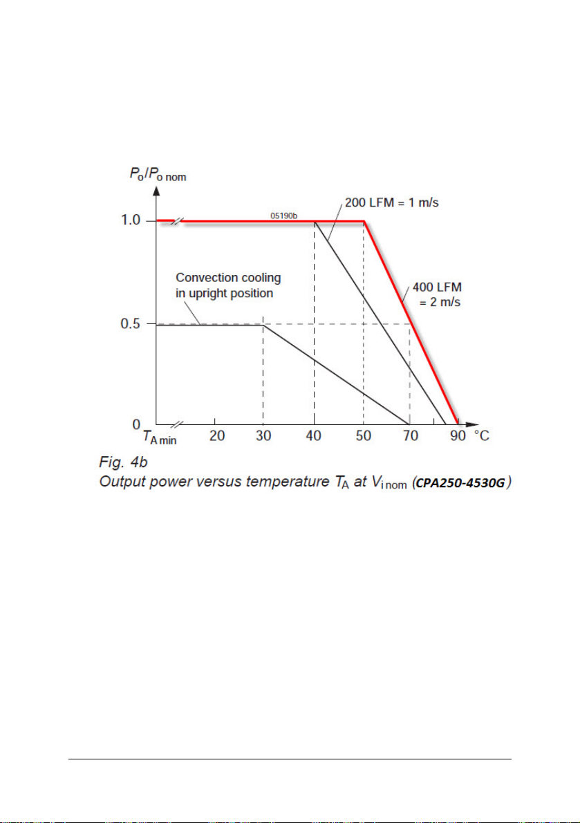
Output power versus temperature T
A
at V
i nom
Power Supply Unit • 39
Page 44

This page intentionally left blank.
40 • Power Supply Unit
Page 45

5 Specifications
5.1 Features
Standard 19” Rack-mount 3U CompactPCI form factor (3U height).
Board Space:
Supports both front and rear access for I/O, CPU, and power supply.
Standard 3U, 21-slot width chassis.
Suitable for rack-mount.
Comprehensive EMC shielding [EMC gaskets are installed on front rails (top
and bottom), rear rails, and side panels].
Power switch.
At least 400 LFM external cooling fans are required
5.2 Mechanical
CompactPCI Standard: 2.0 R3.0
Form Factor: 3U CompactPCI with 50mm depth rear I/O
Enclosure: 19” 3U height rack-mount enclosure
Dimensions: 482.56mm (W) x 133.35mm (H) x 250mm (D)
Usable width: 21 slots (84HP).
Specifications • 41
Page 46

5.3 Environmental
Operating Temperature:
1. cPS-H325/AC: 0°C ~ +50°C ;
2. cPS-P325/AC: -25°C ~ +50°C (Up to 70°C but will have derating issue
when above 50°C. Power efficiency will be derating 2.5% every Celsius
degree and it will only have 50% of power efficiency when 70°C.)
Storage Temperature: -40°C to +85°C.
Humidity: 5% - 95%, non-condensed.
Shock: 15G peak-to-peak, 11ms duration, non-operation.
Vibration:
o
Non-operation:1.88Grms, 5 – 500Hz, each axis.
Operation: 0.5Grms, 5 – 500Hz, each axis.
42 • Specifications
Page 47

Important Safety Instructions
Read and follow all instructions marked on the product and in the
documentation before you operate your system. Retain all safety and
operating instructions for future use.
z Please read these safety instructions carefully.
z Please keep this User‘s Manual for later reference.
z The equipment can be operated at an ambient temperature of 50ºC.
z The equipment should be operated only from the type of power source
indicated on the rating label. Make sure the voltage of the power
source when connect the equipment to the power outlet.
z If your equipment has a voltage selector switch, make sure that the
switch is in the proper position for your area. The voltage selector
switch is set at the factory to the correct voltage.
z For pluggable equipment, that the socket-outlet shall be installed near
the equipment and shall be easily accessible.
z Place the power cord such a way that people can not step on it. Do
not place anything over the power cord.
z If the equipment is not use for long time, disconnect the equipment
from mains to avoid being damaged by transient overvoltage.
z All cautions and warnings on the equipment should be noted.
z Please keep this equipment from humidity.
z Do not use this equipment near water or a heat source.
z Lay this equipment on a reliable surface when install. A drop or fall
could cause injury.
z Never pour any liquid into opening; this could cause fire or electrical
shock.
z Openings in the case are provided for ventilation. Do not block or cover
these openings. Make sure you provide adequate space around the
system for ventilation when you set up your work area. Never insert
objects of any kind into the ventilation openings.
z To avoid electrical shock, always unplug all power cables and modem
cables from the wall outlets before removing covers.
Important Safety Instruction • 43
Page 48

If one of the following situations arises, get the equipment checked by
a service personnel:
A. The power cord or plug is damaged.
B. Liquid has penetrated into the equipment.
C. The equipment has been exposed to moisture.
D. The equipment has not work well or you can not get it work
according to user‘s manual.
E. The equipment has dropped and damaged.
F. If the equipment has obvious sign of breakage.
44 • Important Safety Instruction
 Loading...