

Page 1

cPCIS-1000/2000 Series: 3U CompactPCI
Sub-systems and Components
NuIPC
User’s Guide
Recycled Paper
Page 2

This user’s manual includes the information for the following products range:
Sub-systems: (Single System with LCD)
• cPCIS-2150: 3U CompactPCI Platform with LCD and Off-the-Shelf
ATX PSU
• cPCIS-2151: 3U CompactPCI Platform with LCD and Universal AC
PSU
• cPCIS-2152: 3U CompactPCI Platform with LCD and Dual
Redundant AC PSU
• cPCIS-1151: 3U CompactPCI Platform with LCD and Universal AC
PSU
Sub-systems: (Single System without LCD)
• cPCIS-2100: 3U CompactPCI Platform with Off-the-Shelf ATX PSU
• cPCIS-2102: 3U CompactPCI Platform with Dual Redundant AC
PSU
• cPCIS-1100: 3U CompactPCI Platform with Off-the-Shelf ATX PSU
Sub-systems: (Dual System)
• cPCIS-1250: 3U CompactPCI Platform with Dual System
Components for 3U System
u Power supply options:
• cPS-150R: 3U 175W 31-pin redundant power supply unit
• cPS-175/AC: 3U 175W 47-pin Universal AC input redundant PSU
• cPS-175/48: 3U 175W 47-pin Universal AC input redundant PSU
• cPS-175/25: 3U 175W 47-pin Universal AC input redundant PSU
• cPCI-PSF: Power supply frame for holding PS2-size power supply
• APS-925A: 280W ATX power supply
u Backplane options:
• cBP-3400 Series: 3U 64-bit CompactPCI backplane
• cBP-3100 Series: 3U 32-bit CompactPCI backplane
• cBP-3200 Series: 3U 32-bit CompactPCI backplane with rear I/O
• cBP-3052/3051: Backplane for single/dual 31-pin 3U redundant
power supply
• cBP-3062: Backplane for dual 47-pin 3U redundant power supply
Page 3

u LCD Kit:
• cPCI-LCD: High brightness 6.4” LCD Kit
u Mechanical parts:
• cPCI-PSF: Power supply frame for holding PS2-size power supply
• cPCI-DBF: Drive bay frame for the drive bay
Page 4

Page 5

Copyright 2000 ADLINK Technology Inc.
All Rights Reserved.
Manual Rev. 1.02: August 30, 2000
The information in this document is subject to change without prior notice in
order to improve reliability, design and function and does not represent a
commitment on the part of the manufacturer.
In no event will the manufacturer be liable for direct, indirect, special, incidental,
or consequential damages arising out of the use or inability to use the product
or documentation, even if advised of the possibility of such damages.
This document contains proprietary information protected by copyright. All
rights are reserved. No part of this manual may be reproduced by any
mechanical, electronic, or other means in any form without prior written
permission of the manufacturer.
Trademarks
NuIPC is a registered trademark of ADLINK Technology Inc.
Other product names mentioned herein are used for identification purposes
only and may be trademarks and/or registered trademarks of their respective
companies.
Page 6
Getting service from ADLINK
u Customer Satisfaction is always the most important thing for ADLINK
Tech Inc. If you need any help or service, please contact us and get it.
ADLINK Technology Inc.
Web Site http://www.adlink.com.tw
Sales & Service service@adlink.com.tw
Technical NuDAQ nudaq@adlink.com.tw
Support NuDAM nudam@adlink.com.tw
NuIPC nuipc@adlink.com.tw
NuPRO nupro@adlink.com.tw
Software sw@adlink.com.tw
TEL +886-2-82265877 FAX +886-2-82265717
Address 9F, No. 166, Jian Yi Road, Chungho City, Taipei, 235 Taiwan, R.O.C.
http://www.adlinktechnology.com
u Please inform or FAX us of your detailed information for a prompt,
satisfactory and constant service.
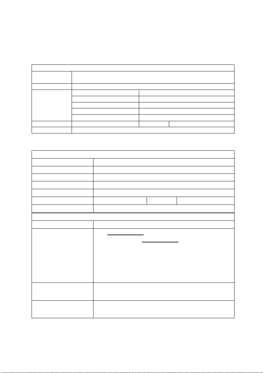
Detailed Company Information
Company/Organization
Contact Person
E-mail Address
Address
Country
TEL
Web Site
FAX
Questions
Product Model
Environment to Use OS
Video Card:
Other:
Computer Brand
M/B: CPU:
Cipset: BIOS:
Network Interface Card:
Challenge Description
Suggestions for ADLINK
Page 7

Table of Contents
How to Use This Manual..................................................iv
Chapter 1 Introduction .....................................................1
Chapter 2 Chassis.............................................................3
2.1 cPCIS-2000 Chassis...........................................................3
2.1.1 Features................................................................................. 3
2.1.2 Mechanical Drawing.............................................................4
2.1.3 Specifications........................................................................4
2.2 cPCIS-1000 Chassis...........................................................6
2.2.1 Specifications........................................................................6
2.2.2 Mechanical Drawing.............................................................6
2.3 3U Power Supply Frame cPCI-PSF.....................................7
2.3.1 Introductions.......................................................................... 7
2.3.2 Features................................................................................. 7
2.3.3 Mechanical Drawing.............................................................7
2.4 3U Drive Bay Frame cPCI-DBF...........................................8
2.4.1 Introductions..........................................................................8
2.4.2 Features................................................................................. 8
2.4.3 Mechanical Drawing.............................................................8
2.5 3U 4HP slot-panel with EMC gasket cPCI-SP3E .................8
Chapter 3 Power Supply Unit...........................................9
3.1 cPS-150R.........................................................................10
3.1.1 Introduction..........................................................................10
3.1.2 The Outline of Power Supply............................................10
3.1.3 Installation...........................................................................11
3.1.4 Specifications......................................................................11
3.1.5 Connector Pin Assignments..............................................14
3.2 cPS-175 Series Power Supply Unit ...................................17
3.2.1 Introduction..........................................................................17
3.2.2 The Outline of Power Supply............................................17
3.2.3 Installation...........................................................................17
3.2.4 Specifications......................................................................18
3.2.3 Connector Pin Assignments..............................................21
3.3 APS-925AX: 280 ATX Power Supply.................................25
3.3.1 Introductions........................................................................25
3.3.2 Specifications......................................................................25
Table of Contents • i
Page 8

Chapter 4 3U Backplane.................................................28
4.1 cBP-3400 Series...............................................................29
4.1.1 Features...............................................................................29
4.1.2 Products List........................................................................29
4.1.3 PCB Drawing.......................................................................30
4.1.4 Specifications......................................................................30
4.1.5 Connectors pin assignments ............................................30
4.2 cBP-3100 Series...............................................................33
4.3 cBP-3200 Series...............................................................34
4.3.1 Features...............................................................................34
4.3.2 Products List........................................................................34
4.3.3 PCB Drawing.......................................................................35
4.3.4 Connectors pin assignments ............................................36
4.4 cBP-3052E Backplane ......................................................39
4.4.1 Specifications......................................................................39
4.4.2 PCB Drawing.......................................................................39
4.4.4 Connectors pin assignments ............................................39
4.5 cBP-3051..........................................................................41
4.5.1 Specifications......................................................................41
4.5.2 PCB Drawing.......................................................................41
4.5.3 Connectors pin assignments ............................................41
4.6 cBP-3062 Backplane.........................................................43
4.6.1 Specifications......................................................................43
4.6.2 PCB Drawing.......................................................................43
4.6.3 Connectors pin assignments ............................................43
Chapter 5 LCD Kit ...........................................................45
5.1 Features ...........................................................................45
5.2 Mechanical Drawing..........................................................45
5.3 Specifications....................................................................46
5.4 Connectors Pin Assignment ..............................................47
Chapter 6 cPCIS-2000 Sub-systems..............................49
6.1 cPCIS-2150 Series............................................................50
6.1.1 Features...............................................................................50
6.1.2 Configurations.....................................................................50
6.1.3 Ordering Options................................................................51
6.2 cPCIS-2151 Series............................................................52
6.2.1 Features...............................................................................52
6.2.2 Configurations.....................................................................52
6.2.3 Ordering Options................................................................52
6.3 cPCIS-2100 Series............................................................54
6.3.1 Features...............................................................................54
ii • Table of Contents
Page 9

6.3.2 Configurations.....................................................................54
6.3.3 Ordering Options................................................................55
6.4 cPCIS-2102 Series............................................................56
6.4.1 Features...............................................................................56
6.4.2 Configurations.....................................................................56
6.4.3 Ordering Options................................................................56
6.5 cPCIS-2152 Series............................................................58
6.5.1 Features...............................................................................58
6.5.2 Configuration.......................................................................58
6.5.3 Ordering Options................................................................58
Chapter 7 cPCIS-1000 Sub-systems..............................60
7.1 cPCIS-1151 ......................................................................61
7.1.1 Features...............................................................................61
7.1.2 Configurations.....................................................................61
7.1.3 Ordering Options................................................................61
7.2 cPCIS-1100 Series............................................................62
7.2.1 Features...............................................................................62
7.2.2 Configurations.....................................................................62
7.2.3 Ordering Options................................................................62
7.3 cPCIS-1250 ......................................................................64
7.3.1 Features...............................................................................64
7.3.2 Configurations.....................................................................64
7.3.3 Ordering Options................................................................64
Product Warranty/Service..............................................65
Table of Contents • iii
Page 10

How to Use This Manual
This manual is designed to help you use the cPCI-2000/1000 Series 3U
CompactPCI Sub-system. It is divided into five chapters:
u Chapter 1, "Introduction," gives an overview of the product features.
u Chapter 2, "Chassis," describes the specifications and installation of
the chassis.
u Chapter 3, "Power Supply," describes the using of power supply.
u Chapter 4, "Backplane", describes the backplane specifications.
u Chapter 5, "LCD Kit", describes the specifications of 6.4” LCD kit.
u Chapter 6, "Sub-system", describes the specifications of sub-systems.
iv • How to Use This Manual
Page 11

1
Introduction
This users manual gives you the following information about the cPCI -2000
series 3U CompactPCI sub-systems, including the brief introduction of the
components and the detail specifications of the sub-systems.
The cPCI-2000 series sub-systems are assembling by the following major
components:
Components:
u Chassis options:
• cPCIS-1000: 3U CompactPCI card cage
• cPCIS-2000A: 3U CompactPCI chassis with 2 Fans
• cPCIS-2000B: 3U CompactPCI chassis with 4 Fans
• cPCI-PSF: Power supply frame for holding PS2-size power supply
• cPCI-DBF: Drive bay frame for the drive bay
u Power supply options:
• cPS-150R: 3U 175W 31-pin redundant power supply unit
• cPS-175/AC: 3U 175W 47-pin Universal AC input redundant PSU
• cPS-175/48: 3U 175W 47-pin Universal AC input redundant PSU
• cPS-175/25: 3U 175W 47-pin Universal AC input redundant PSU
• APS-925A: 280W ATX power supply
u Backplane options:
• cBP-3400 Series: 3U 64-bit CompactPCI backplane
• cBP-3100 Series: 3U 32-bit CompactPCI backplane
Introduction • 1
Page 12

• cBP-3200 Series: 3U 32-bit CompactPCI backplane with rear I/O
• cBP-3052/3051: Backplane for single/dual 31-pin 3U redundant
power supply
• cBP-3062: Backplane for dual 47-pin 3U redundant power supply
u LCD Kit:
• cPCI-LCD: High brightness 6.4” LCD kit
We also provide sub-systems based on the above optional components.
Whenever the sub-systems cannot fully meet users’ requirement, please
contact with us for discussing the possibility for more options. To form a
complete starting kit, users need to order other CPU modules, which are not
specified here.
Sub-systems: (Single System with LCD)
• cPCIS-2150: 3U CompactPCI Platform with LCD and Off-the-Shelf
ATX PSU
• cPCIS-2151: 3U CompactPCI Platform with LCD and Universal AC
PSU
• cPCIS-2152: 3U CompactPCI Platform with LCD and Dual
Redundant AC PSU
• cPCIS-1151: 3U CompactPCI Platform with LCD and Universal AC
PSU
Sub-systems: (Single System without LCD)
• cPCIS-2100: 3U CompactPCI Platform with Off-the-Shelf ATX PSU
• cPCIS-2102: 3U CompactPCI Platform with Dual Redundant AC
PSU
• cPCIS-1100: 3U CompactPCI Platform with Off-the-Shelf ATX PSU
Sub-systems: (Dual System)
• cPCIS-1250: 3U CompactPCI Platform with Dual System
The following chapters will describe the specifications of the above
components or sub-systems.
2 • Introduction
Page 13

2
Chassis
In this chapter, we will describe the detail features and specifications of the
cPCIS-1000 and cPCIS-2000 chassis. Other mechanical parts which may be
used to assembly the system also be described.
2.1 cPCIS-2000 Chassis
2.1.1 Features
u Standard 19” 3U CompactPCI form factor, 4U in height
u Boards Space:
• Board space for I/O, CPU and power supply is standard 3U height,
21-slot width
• Both front access or rear access are possible
• With versatile backplane options, can assembly to many sub-
systems with different configurations
u Two (or four) built-in pushing fans are used for self-cooling system. All
fans and air-filter are removable on the bottom side
u Suitable for both rack-mount and desktop applications
• Side handle are designed for portable instrument
• Two adjustable foot stands are designed for desktop applications
u Comprehensive EMC shielding: EMC gaskets are installed on the front
rails (up and down), rear rails and the side panels
Chassis • 3
Page 14
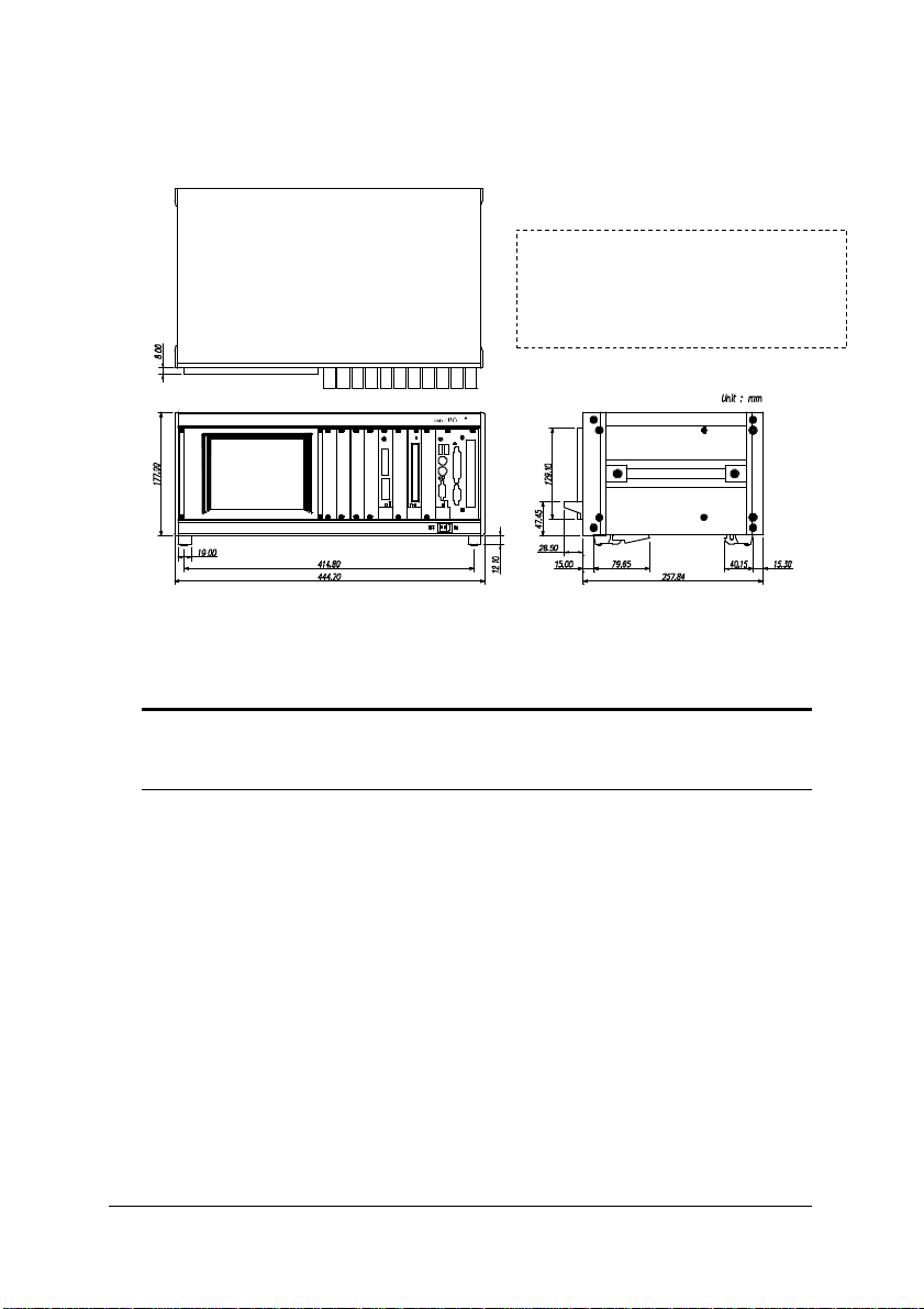
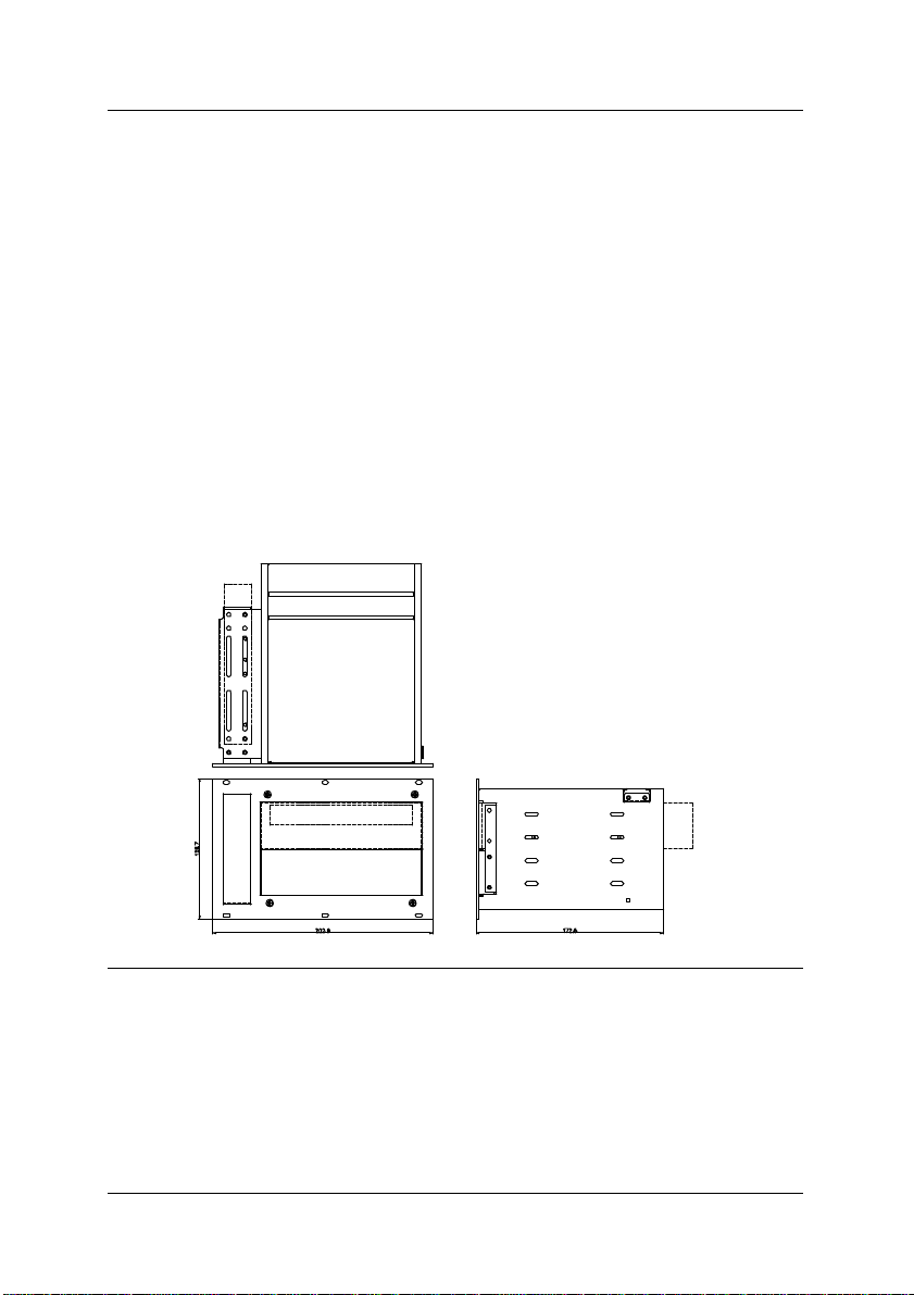
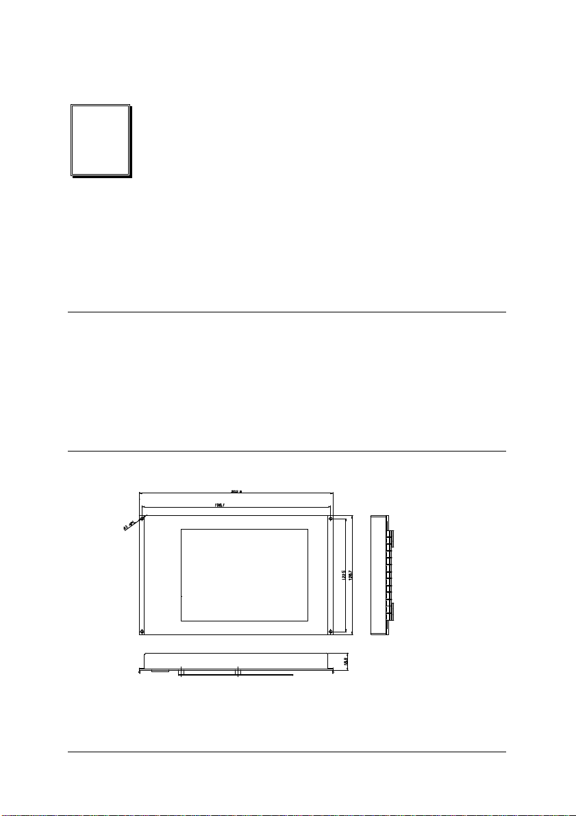
ADLINK
This drawing is for showing the
mechanical dimension only, the
components inside the chassis is
dependent on every different model
number
.
2.1.2 Mechanical Drawing
Note:
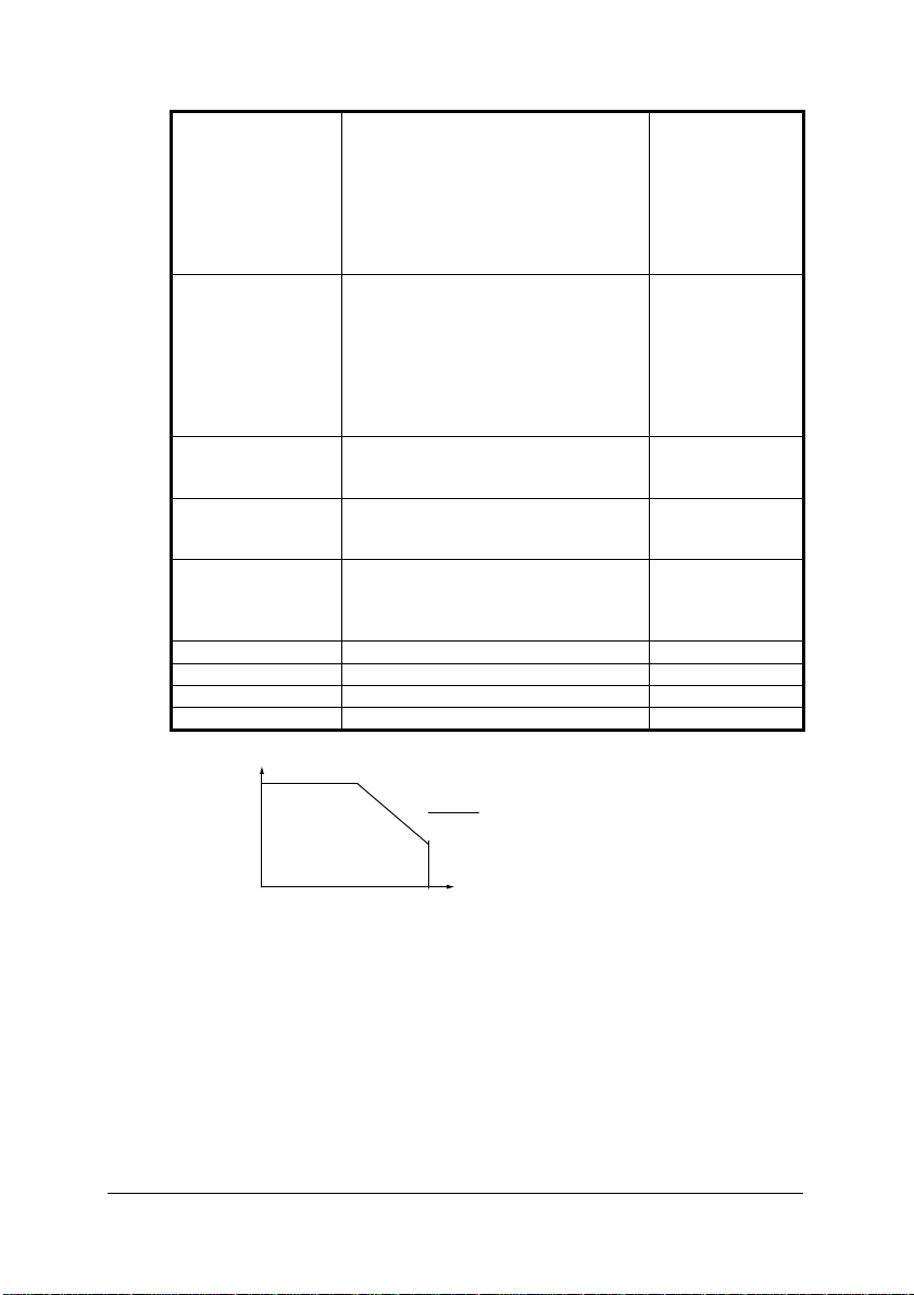
2.1.3 Specifications
u Dimension: 444.2(W) mm x 177(H) mm x 257.9(D) mm
Note : 1. Width is 482.6 mm (19”) with rack-mounting kit.
2. 177.0 mm is to fit 4U height. Total height is 189.1 mm with foot
stands.
u Usable width: 21 slots (84HP)
u Internal pushing FAN on the bottom:
• Fan type: DC brushless motor
• Numbers of FAN:
n 2 Fans for cPCIS-2000A
n 4 Fans for cPCIS-2000B
• Rated voltage: 12V @ 0.43A (use –12V of system power)
• Input Power: 5.16W (rated); 7.7W (maximum)
• Maximum Air flow: 60 CFM (when zero static pressure)
• Operating Temperature: -10 ~ 70 degree C
u Internal FAN controller:
• Designed to utilize the system –12V for FAN power
4 • Chassis
Page 15
• Current control of the FAN to provide stable fan operation
• Fan failure detection ready to use
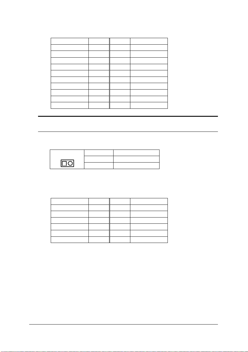
• Power input connector (CN101)
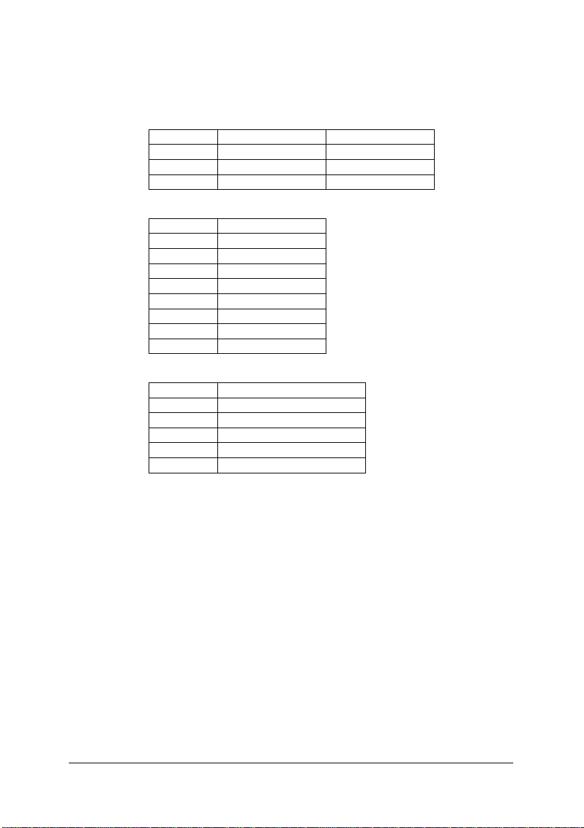
Pin # Signal Cable color
1 -12V Yellow
2 GND Black
3 +5V Red
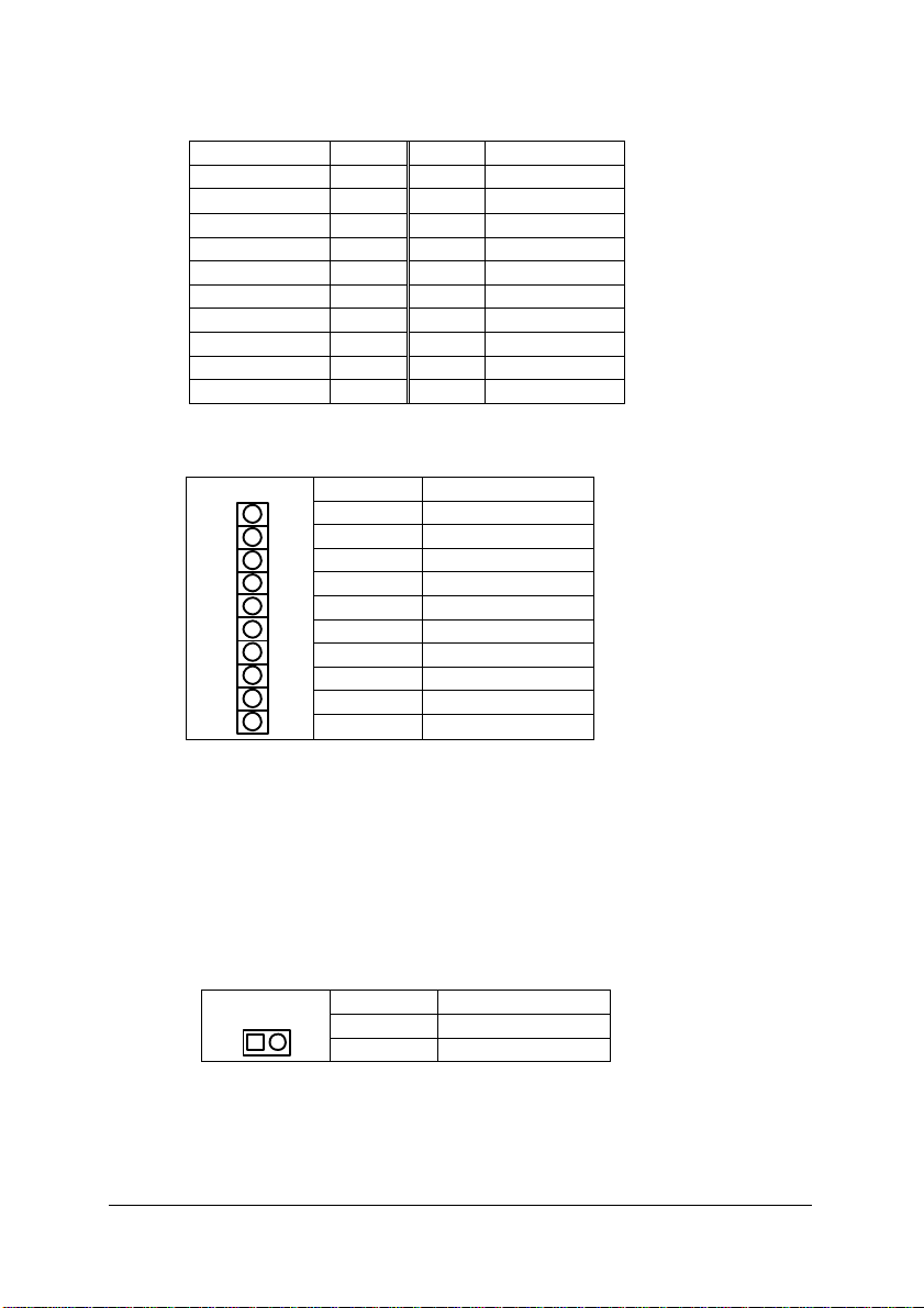
• Connector to Fans (CN102)
Pin # Signal
1 GND
2 Fan #1 power
3 GND
4 Fan #2 power
5 GND
6 Fan #3 power
7 GND
8 Fan #4 power
• Fan failure output (CN103)
Pin # Signal
1 +5V
2 Fan #1 failure output
3 Fan #2 failure output
4 Fan #3 failure output
5 Fan #4 failure output
• Power requirement:
n +5V: 40 mA maximum
n -12V: 200 mA plus fans’ power consumption, which is
dependent on numbers of fans
Chassis • 5
Page 16
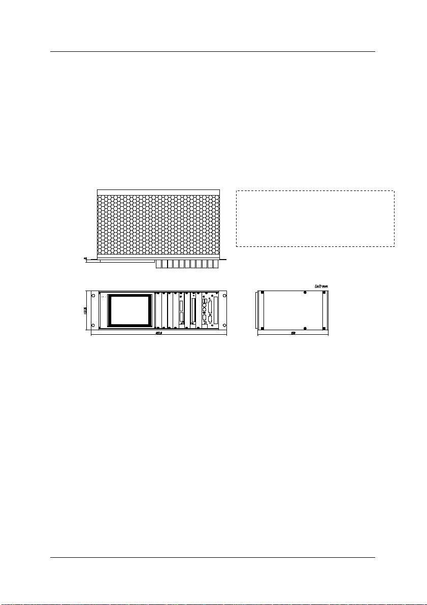
Th
is drawing is for showing the
mechanical dimension only, the
components inside the chassis is
dependent on every different model
2.2 cPCIS-1000 Chassis
2.2.1 Specifications
u 19” rack-mount 3U in height, 21-slot CompactPCI card cage
u Need external fan for cooling
u Dimension: 482.56 (W) mm x 133.35 (H) mm x 250.0 (D) mm
2.2.2 Mechanical Drawing
Note:
number.
6 • Chassis
Page 17

2.3 3U Power Supply Frame cPCI-PSF
2.3.1 Introductions
The cPCI-PSF is a power supply frame, which is designed for holding the
PS2 size power supply in a 3U CompactPCI card cage. Four standard
card guides are necessary for guiding the position of this frame. Any PS2
sized power supply unit can be used together with cPCI-PSF.
2.3.2 Features
u To fit standard 3U CompactPCI form factor with 9-slot (36HP) width.
Dimension: 182.6 mm x 128.7 mm x 94.5 mm
u Any standard PS2 sized power supply unit can be fit
u Rugged mechanical design, the frame is held on the standard card
guide position
2.3.3 Mechanical Drawing
Chassis • 7
Page 18
2.4 3U Drive Bay Frame cPCI-DBF
2.4.1 Introductions
The cPCI-DBF is a drive bay frame, which is designed for holding the FDD,
HDD or CD-ROM drives in a 3U CompactPCI card cage. The drive bay
can support two 5 1/4” drives and one 3 1/2” drive.
2.4.2 Features
u To fit standard 3U CompactPCI form factor with 10-slot (40HP) width.
Dimension: 202.9 (W) mm x 128.7 (H) mm x 172.5. (D) mm
u Support two 5 1/4” drives and one 3 1/2” drive
u Rugged mechanical design
2.4.3 Mechanical Drawing
2.5 3U 4HP slot-panel with EMC gasket cPCI-SP3E
The 3U CompactPCI chassis are shipped with the slot-panel, which is
without EMC spring. Users can order the cPCI-SP3E, which is a Ushaped 4HP width slot-panel with the EMI spring. To use cPCI-SP3E on
the blank slots is necessary for EMI shielding.
8 • Chassis
Page 19

3
Power Supply Unit
The power supply unit in the 3U CompactPCI system is with modular design.
The users can chose the most suitable solution for the specified applications.
There are many kinds of power supply unit can be installed in 3U
CompactPCI card cage. In this chapter, the features and specifications of
the following power supply unit or modules are shown.
u Redundant Power Supply
• cPS-150R: 3U 175W universal AC input redundant power supply
(31-pin)
• cPS-175/AC: 3U 175W universal AC input redundant power supply
(47-pin)
• cPS-175/48: 3U 175W –48V DC input redundant power supply
(47-pin)
• cPS-175/24: 3U 175W –24V DC input redundant power supply
(47-pin)
u PS2-size Power Supply
• APS-925A: 280W Auto-switched AC input ATX Power Supply
Power Supply Unit • 9
Page 20
3.1 cPS-150R
3.1.1 Introduction
cPS-150R is a redundant power supply which designed for CompactPCI
standard industrial computer. It provides hot-swappable function, and can
make the output current shared in parallel. It provides good quality power and
instant maintenance to a system.
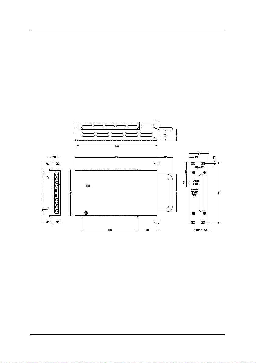
3.1.2 The Outline of Power Supply
Figure 3.1.2 The Outline of cPS-150R Power Supply
Functions of LED
POWER: The Power LED is lit Green if the AC input power has been turned
on.
FAIL: If LED is with light, it indicates that the power unit is defective. It means
short circuit, over voltage (+5V or +3.3V), over temperature, or at least the
loading of one channel is out of specification. It also means that input voltage
is under or over specification.
10 • Power Supply Unit
Page 21
3.1.3 Installation
WARNING
After inserting cPS-150R to a standard 3U CompactPCI system or the
standard 6U CompactPCI system, you can turn on the switch on the chassis.
Of course, you may turn on the power switch on the chassis first, and insert
cPS-150R, which delivers full safety redundant, hot-swappable function, and
provides the plug-able feature.
Be sure that the socket of the backplane on the
chassis is ERNI part #914374; AMP#148370-1 or
#97-7200 defined by PICMG before inserting
cPS-150R to the chassis. If cPS- 150R is forcibly
inserted, it and the connector of the chassis will
be damaged.
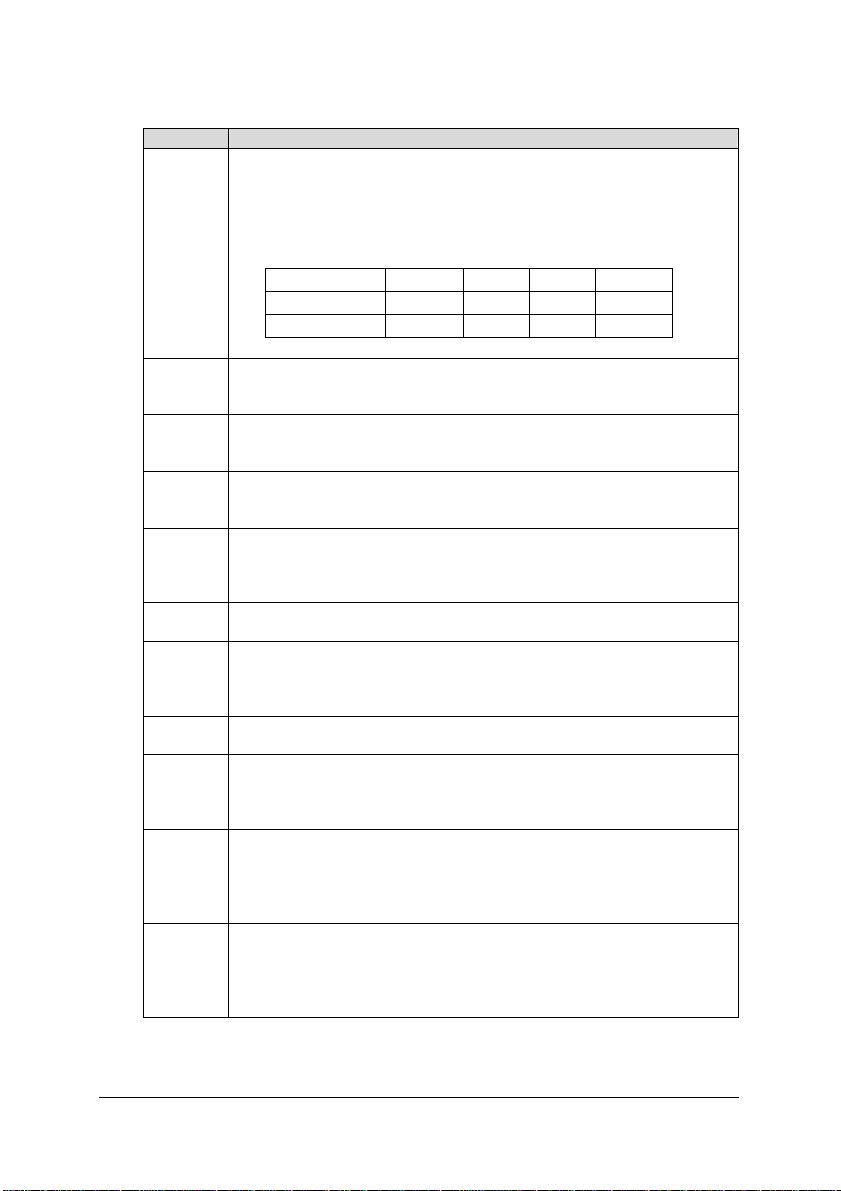
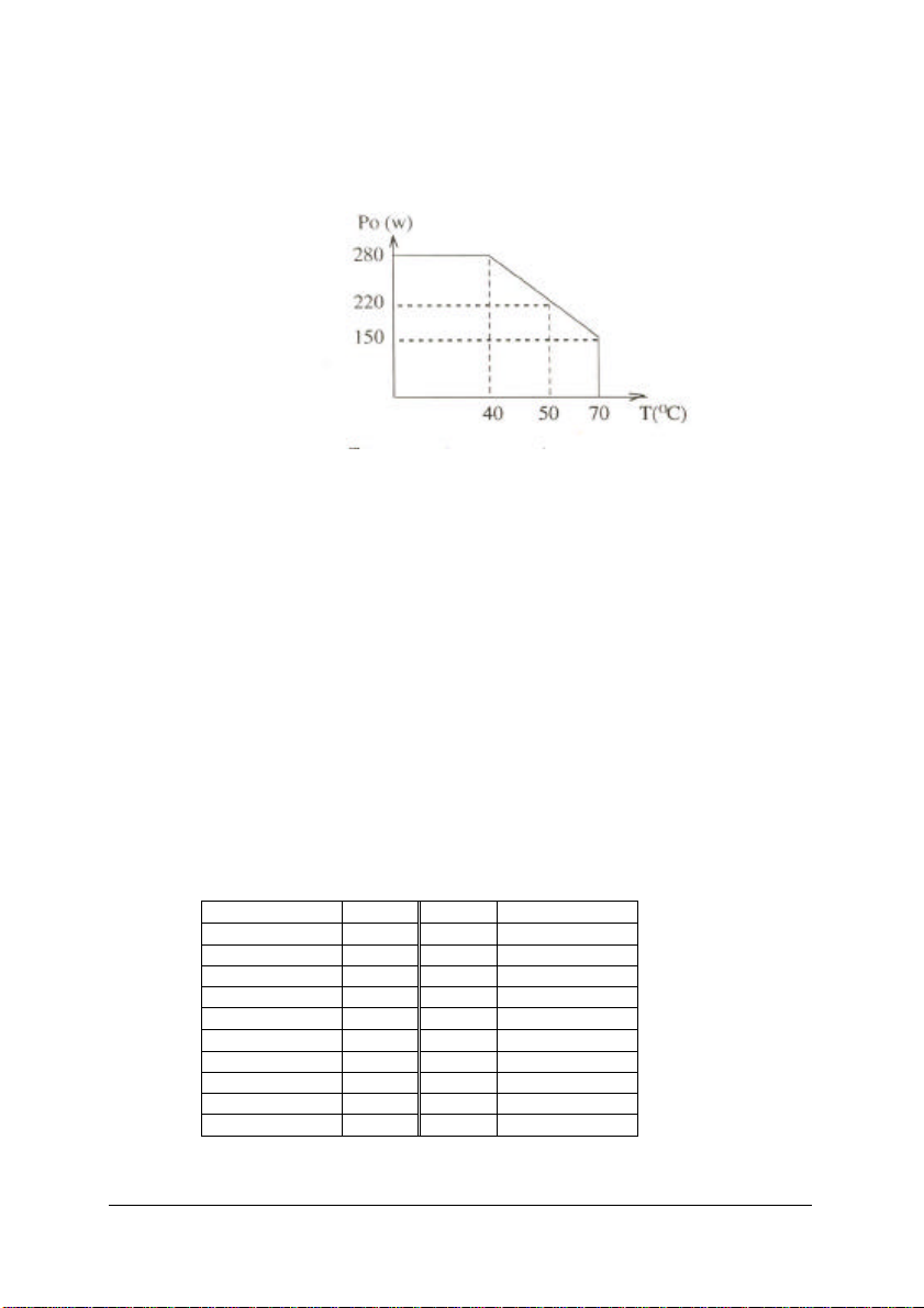
3.1.4 Specifications
u AC Input
Item Specification Test Conditions
Operating Voltage 90 - 264 Vac, single phase
Input current 3.1 A max
Inrush current <40A @ 240 Vac
Frequency range 45-440 Hz
Power factor 0.99 typical
Efficiency typical 73%
Protection over current, over voltage, under
u DC Output
Item Specification Test Conditions
Output power 175W max. For working area
Output voltage
Output current 20A @+5V (2A min.)
Voltage error
voltage, and surge protection.
+5V, +3.3V, +12V, −12V
12A @+3.3V
2A @+12V
1A @−12V
< ±3% @+5V
< ±5% @+3.3V
< ±5% @+12V
< ±5% @−12V
refer to figure
3.1.4
Power Supply Unit • 11
Page 22
th a capacitor of
Ripple voltage +5V............... 1.0 % p-p
Current sharing in
parallel
Load regulation The output voltage of +5V changes
Line regulation The output voltage of +5V changes
Hold up time >6ms
Rising time <200ms
Temperature
coefficient
Protection All outputs protected against overload
+3.3V............ 1.5 % p-p
+12V............. 1.0 % p-p
-12V ............. 1.0 % p-p
Any number of power supplies can be
operated in parallel and will share
current to within 10%
within ±3% of allowed value.
within ±0.1% of allowed value.
0.05% / °C
and short circuit. Straightline current
limiting, does not fold-back or latch-up
during startup or load transients.
Automatic recovery.
Shutdown at internal heatsink
temperature of 95°C. Automatic
recovery.
Shutdown at the output voltage
exceeds the nominal voltage 20%.
Recycle power to reset.
The testing probe
must be in parallel
wi
22µF and that of
0.1µF.
only at +5V output
Input voltage is
from 90Vac to
260Vac. Load is
from 10% to
100%.
Input voltage is
from 90Vac to
260Vac. Load is
from 10% to
100%.
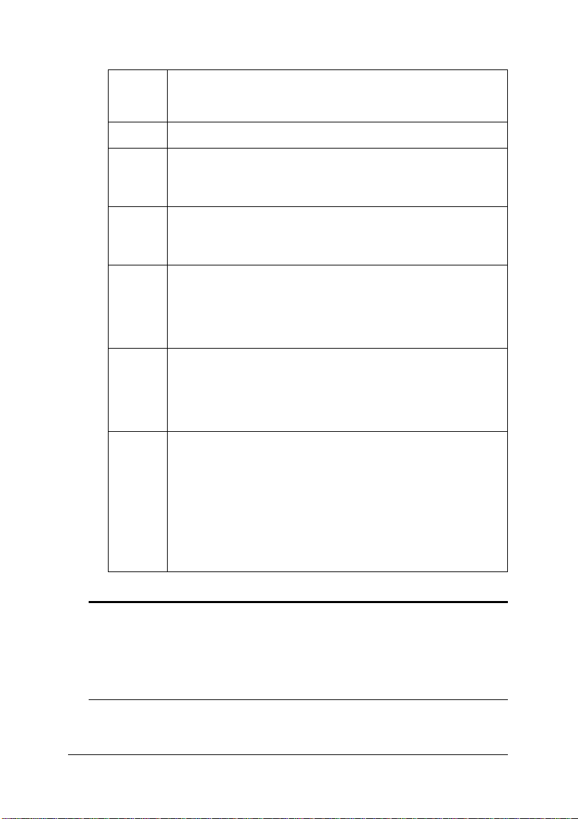
u Others
Item Specification Test Conditions
Input/output
connector
Indicator Normal (green LED)
Switching frequency 100KHz
MTBF 50,000 hours MIL-HDBK-217E
MTTR 5 minutes
EMC meets FCC and Class A of VDE
Safety specification UL 1950, CSA C22.2 NO.950,
CE EMI: EN61000-3-2(1995),
Male base is on the rear of power
supply, and must meet IEC 603-2
(DIN 41612) or IEC 1076.
Fail (red LED)
EN60950/ TüV
EN61000-3-3
harmonics
12 • Power Supply Unit
Page 23
meets EN55022 Class A
0
10 20 30 40 50 60 70
100
50
0
forced air 15 cfm
EMS:EN 50082-2
EN61000-4-2
EN61000-4-3
EN61000-4-4
EN61000-4-6
EN61000-4-8
ENV 50204
Impact & vibration
test
Insulating strength Primary - secondary: 4242Vrms
Output insulation Relatively to chassis ground, all
Operation
temperature
Storing temperature
Relative humidity <95% @ 40°C, none condensation
Operation height 6,400m
Weight about 0.85Kg
Frequency Range:
5Hz – 35Hz 5 min
35Hz – 55Hz 5 min
55Hz – 5Hz 5 min
Displacement: 0.38mm
Dweep time: 30 minutes for each axis
Duration: 2 cycles for three orthogonal
axis. Axis: X, Y, Z
Primary - chassis ground: 3050Vrms
secondary - chassis ground: 500Vrms
control signals and outputs are
floating SELV circuits.
0°C~70°C(the temperature on the
chassis)
Full power from 0°C to 40°C with 15
cfm forced air flow
− 40°C to +85°C
Unpackaged,
Non-operating
Ambient °C
Figure 3.1.4 Working Area
Power Supply Unit • 13
Page 24
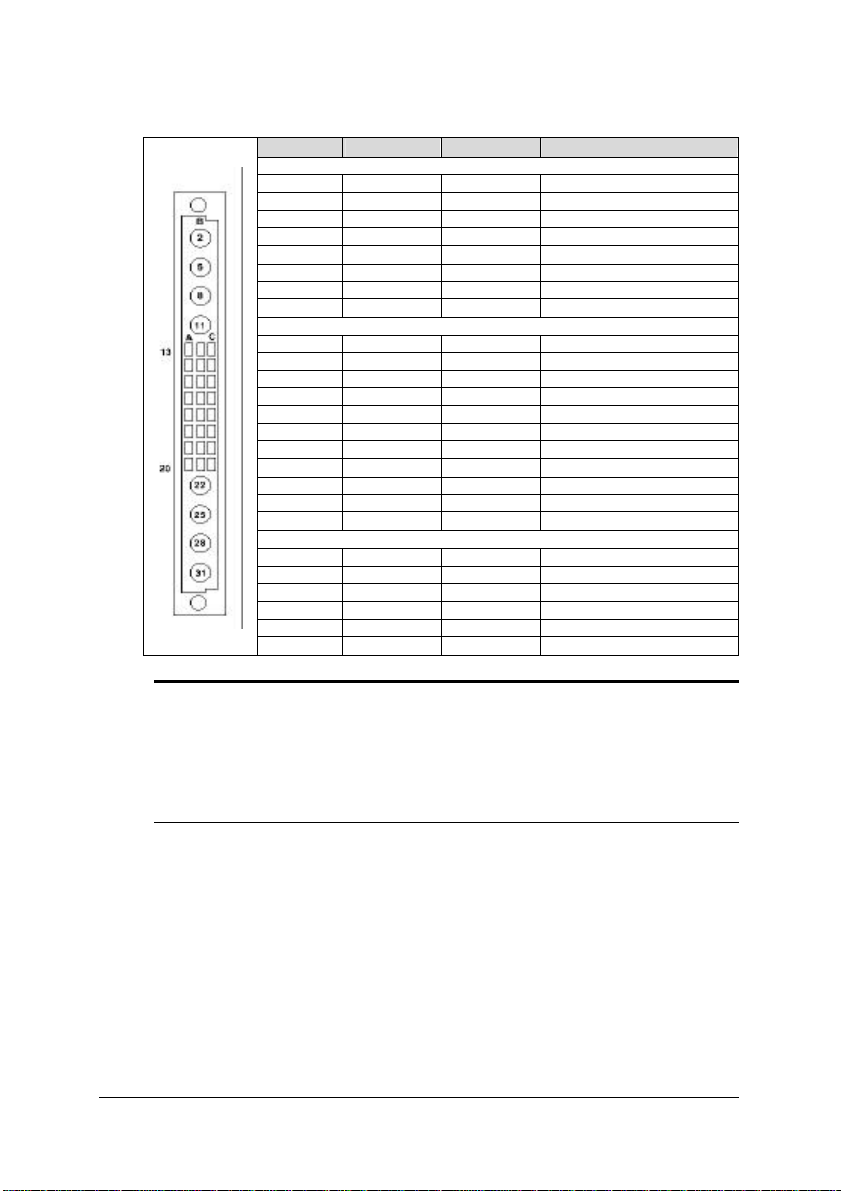
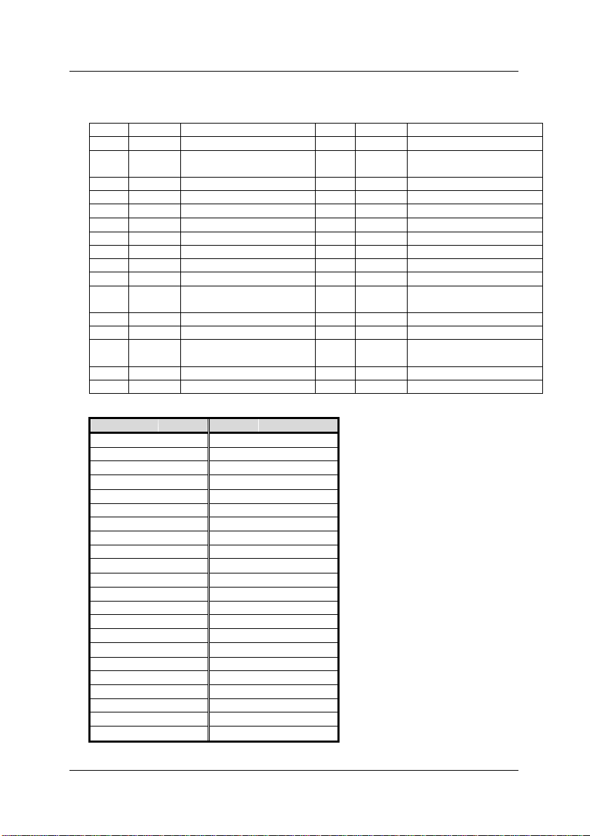
3.1.5 Connector Pin Assignments
(1)
Pin #
Column A
Column B
Column C
Staging
A13 EL SP Spare
A14 EL INH# Inhibit Signal
A15 EL ISH Current Share Signal
A16 EL 5S- 5V Sense −
A17 EL 5S+ 5V Sense +
A18 EL 3.3V +3.3 VDC
A19 EL +12V +12 VDC
A20 EL −12V −12 VDC
B2 SL ACL AC Line
B5 SL ACN AC Neutral
B8 - - No Pin Loaded
B11 EL CG
B13-18 SL 3.3V +3.3 VDC
B19 SL +12V +12 VDC
B20 SL −12V −12 VDC
B22 EL 5V +5 VDC
B25 EL GND Ground
B28 EL +DC +DC Input
B31 EL −DC −DC Input
C13 SL EN# Enable Signal
C14 SL DEG# Derate Signal
C15 SL FAL# Supply Fail Signal
C16-18 SL 3.3V +3.3 VDC
C19 SL +12V +12 VDC
C20 SL −12V −12 VDC
(2)
Mnemonic Description
(3)
Chassis Ground
Note: 1. Mating pin numbers on power supply connector.
2. EL is an Extra Length pin. SL is a Standard Length pin.
3. CG must be connected to earth ground.
4. Mating Connector (top view) Pin numbers illustrated are the
pin view of the female mating connector. A mating connector
is ERNI part #914374; AMP #148370-1 or #97-7200-016.
14 • Power Supply Unit
Page 25
Definitions of Pin Signals
Signal Definition
INH# Inhibit signal MAY be used to “turn off” the power supply outputs. This
ACL AC Line input SHALL be used for supplies operating from AC. This
ACN AC Neutral input SHALL be used for supplies operating from AC. This
+DC Positive DC input SHALL be used for supplies operating from DC. This
−DC
EN# Enable signal MAY be used to “turn on” the power supply outputs. EN#
DEG# Derating signal MAY be used as an output from the power supply to
FAL# Supply Fail signal MAY be used as an output from the power supply to
signal is on a longer pin than the EN#(enable) signal and therefore has
precedence over the EN# signal when determining power supply
operation (see table below). The INH# signal is typically connected to
an “ON/OFF” switch. This signal is optional.
Module Power Supply Operation
INH# = Low Low High High
EN# = Low High Low High
Power Status “OFF” “OFF” “ON” “OFF”
ISH Current Share signal MAY be used between multiple power supplies
for load balancing. This signal is not required for single power supply
systems.
5V Sense – SHALL be connected to the center of the ground plane for
5S−
accommodating power distribution losses. This signal is required for all
modular power supplies.
5S+ 5V Sense + SHALL be connected to the center of the power plane for
accommodating power distribution losses. This signal is required for all
modular power supplies.
input is not required for DC input power supplies. Separate AC and DC
inputs are provided to prevent damaging an AC power supply inserted
into a backplane wired for DC and visa versa.
input is not required for DC input power supplies.
input is not required for AC input power supplies. Separate AC and DC
inputs are provided to prevent damaging a DC power supply inserted
into a backplane wired for AC and visa versa.
Negative DC input SHALL be used for supplies operating from DC.
This input is not required for AC input power supplies.
is used in conjunction with INH# (see table of INH#) and is typically
connected to ground to enable the power supply after signals on longer
pins have made contact. This signal is optional.
indicate that the supply is beginning to derate its power output. This
signal is optional. Note that backplanes providing a modular power
supply connector shall connect DEG# to the backplane signal DEG# in
the event that a power supply implementing this signal is installed.
indicate that it has failed. This signal is optional. Note that backplanes
providing a modular power supply connector shall connect FAL# to the
backplane signal FAL# in the event that a power supply implementing
this signal is installed.
Power Supply Unit • 15
Page 26

Caution: Improperly connected 5S+ and 5S- leads may damage the power
supply.
16 • Power Supply Unit
Page 27

3.2 cPS-175 Series Power Supply Unit
3.2.1 Introduction
cPS-175 series products are a power supply designed for CompactPCI
standard industrial computer. Based on the CompactPCI standard design, it
has hot-swappable function, and can make the output current shared in
parallel. It provides good quality power and instant maintenance to a system.
They are compliant with the PICMG 2.11 specifications.
3.2.2 The Outline of Power Supply
3.2.3 Installation
After installing the cPS-175 power supply to a CompactPCI 3U/6U chassis,
you can turn on the power switch on the chassis. You may also turn on the
power switch on the chassis first, then install the power supply as it has full
safety redundant, hot-swappable function and pluggable feature.
A Warning : Be sure that the backplane socket on the chassis is
Positronic part PCIH47F300A1, PCI47F300A1 which is defined by
PICMG 2.11 before installing cPS-175 series power supply to the
chassis. It could damage the power supply unit and the chassis
connector if it is installed forcibly.
Power Supply Unit • 17
Page 28

There are two external warning LEDs.
POWER: The Power LED is lit green if the AC or DC external power input
power has been turned on.
FAULT: If LED is with light, it indicates that the power unit is defective. It
means the input voltage is out of the range, or over temperature, over current,
or short circuit.
3.2.4 Specifications
Input
Item cPS-175/AC cPS-175/48 cPS-175/24
Voltage 90 – 264 Vac 36 – 72 VDC 18 - 36 VDC
Input Current <5A <9A <20A
Inrush Current <40A @ 240V AC <40A <40A
Frequency 50 – 60 Hz
Power Factor 0.99 typical
Efficiency Typical 73% Typical 73% Typical 73%
Protection Fuse, Over Voltage,
Under Voltage, Surge
Protection
Note:
Current = 5A max.
Voltage: 270 Vmax
85Vmin.
Output
Item cPS-175/AC cPS-175/48 cPS-175/24
Rated Power 175W maximum 175W maximum 175W maximum
Voltage +5V, +3.3V, +12V, -12V
Current 25A @ +5V*1
Voltage Error
Ripple Voltage 100mV or 1 % whichever is greater
Current Sharing Any number of power supplies can be operated in parallel and will
share +5V and +3.3V current to within 10%.
Load regulation
Line regulation
Hold-up time > 6ms
Rise time < 500ms from AC/DC power up. All output voltages come up within 10
msec of each other.
25A @ +3.3V
3A @ +12V
1A @ -12V
Combined current @ +5V & +3.3V < 27A
< ±3% @ +5V
< ±5% @ +3.3V
< ±5% @ +12V
< ±5% @ -12V
Fuse, Over Voltage,
Under Voltage, Surge
Protection
Note:
Current = 10A max.
Voltage: 75 Vmax.
35 Vmin.
±1%@+5V
±3%@+3.3V / +12 V / -12V
±0.3%
Fuse, Over Voltage,
Under Voltage, Surge
Protection
Note:
Current = 20 A max.
Voltage: 40 Vmax.
16 Vmin.
18 • Power Supply Unit
Page 29

Temperature
Coefficient
Protection 1. All outputs protected against overload and short circuit. Straightline
current limiting, does not fold-back or latch-up during startup or load
transients. Automatic recovery.
2. Shutdown at internal heatsink temperature of 95°C. Automatic
recovery.
3. Shutdown at the output voltage exceeds the nominal voltage 20%.
Recycle power to reset.
0.05% / °C
Other
Item cPS-175/AC cPS-175/48 cPS-175/24
Output/Input
Connector
Indicator Green LED indicating INPUT O.K.
Switching
Frequency
MTBF 100,000hr (by part counting MIL-HDBK0217E)
MTTR 5 Minutes (based on module replacement)
Safety TUV/VDE EN60950
CE EMI: EN55022 Class A radiated and conducted
Shock &
Vibration
Insulation Primary –
Output Insulation Floating & SELV
Operating
Temperature
Storage
Temperature
Humidity < 95% @ 40°C
Altitude 6,400m
Dimension
Weight about 0.85kg
Red LED indicating a power supply FAULT.
EMS:EN 50082-2 (IEC1000-4-2, IEC1000-4-4, IEC-4-5, IEC1000-4-11)
Frequency range: 5Hz~35Hz (5 min); 35~55Hz (5 min); 55~5Hz(5 min)
Displacement: 0.38 mm
Dweep time: 30 mins for each axis (X,Y,Z) duration 2 cycles for the
three orthogonal axis
Secondary: 3050Vrms
Primary – Chassis
Ground:3050Vrms
Secondary – Chassis
Ground:500Vrms
0°C~ 70°C(the temperature on the chassis)
Full power from 0°C to 40°C with 15 cfm forced air flow
40.0 (W)× 128.5(H) × 172.8(D) mm
Positronic
PCI47M400A1
100kHz
UL
Primary –
Secondary:1150Vrms
Primary – Chassis
Ground:500Vrms
Secondary – Chassis
Ground:500Vrms
-10°C ~+85°C
Primary –
Secondary:1150Vrms
Primary – Chassis
Ground:500Vrms
Secondary – Chassis
Ground:500Vrms
Note : minimal load 2 A @ +5V is required.
Power Supply Unit • 19
Page 30

0
10 20
30 40 50 60 70
100
500
forced air 15 cfm
Operating Area
Ambient °C
20 • Power Supply Unit
Page 31

3.2.3 Connector Pin Assignments
42 43 44
4
7
The Type of Connector
Pin Signals
Pin# Signal Name Pin# Signal Name
1-4 V1 32 V2 ADJ
5-12 RTN 33 V2 SENSE
13-18 V2 34 S RTN
19 RTN 35 V1 SHARE
20 V3 36 X
21 V4 37 X
22 RTN 38 DEG#
23 X 39 INH#
24 RTN 40 X
25 GA0 41 V2 SHARE
26 X 42 FAL#
27 EN# 43 X
28 GA1 44 X
29 V1ADJ 45 CGND
30 V1 SENSE 46 ACN/+DC IN
31 GA2 47 ACL/-DC IN
46
45
39 40 41
36 37 38
33 34 35
30 31 32
27 28 29
24, 25 26
21 22 23
19 20
17 18
15 16
13 14
11 12
9 10
7 8
5 6
3 4
1 2
Positronic Industries
Part Number:
PCI47M400A1
or PCIH47M400A1.
View from mating face
Power Supply Unit • 21
Page 32

uld be used to "turn off" the power supply outputs.
This signal is on a longer pin than the EN# ( enable ) signal and
therefore has precedence over the EN# signal when determining
power supply operation. The INH# signal is typically connected to an
voltage input for supplies operating from AC, or the +DC voltage
Definitions of Pin Signals
Signal Definition
EN# Enable signal should be used to "turn on" the power supply outputs.
INH# Inhibit signal sho
SHARE
SHARE
SENSE
RTN
RTN Return shall be connected via a low impedance to the backplane's
V1SENSE V1 (+5V) Sense shall be connected to the center of the backplane's
V2SENSE V1 (+3.3V) Sense shall be connected to the center of the
ACL/
-DC IN
ACL/
+DC IN
EN# is used in conjunction with INH# (see Table 2.1) and is typically
connected to ground to enable the power supply after other signals
on longer pins have made contact.
"ON/OFF" switch. Table 2.1 Module Power Supply Operation
INH# = Low Low Open Open
EN# = Low Open Low Open
Power Status “OFF” “OFF” “ON” “OFF”
V1
V1(+5V) Current Share signal may be used between multiple power
supplies for load balancing. This signal is not required for single
power supply systems.
V2
V1(+3.3V) Current Share signal may be used between multiple
power supplies for load balancing. This signal is not required for
single power supply systems.
Return Sense shall be connected to the center of the backplane's
ground plane for accommodating power distribution losses. This
signal is required for modular power supplies.
V1 V1( +5V ) shall be connected via a low impedance to the backplane's
power plane for minimizing power distribution losses. This signal is
required for all modular power supplies.
V2 V1( +3.3V ) shall be connected via a low impedance to the
backplane's power plane for minimizing power distribution losses.
This signal is required for all modular power supplies.
V3 V1( +12V ) shall be connected via a low impedance to the
backplane's power plane for minimizing power distribution losses.
This signal is required for all modular power supplies.
V4 V1( -12V ) shall be connected via a low impedance to the
backplane's power plane for minimizing power distribution losses.
This signal is required for all modular power supplies.
ground plane for minimizing power distribution losses. This signal is
required for modular power supplies.
power plane for accommodating power distribution losses. This
signal is required for all modular power supplies.
backplane's power plane for accommodating power distribution
losses. This signal is required for all modular power supplies.
AC Line/Negative DC input shall be used as the AC Line voltage
input for supplies operating from AC, or the -DC voltage input for DC
input power supplies.
AC Neutral/Positive DC input shall be used as the AC Neutral
22 • Power Supply Unit
Page 33
input for DC input power supplies. Front panel keying is provided to
prevent damaging an AC power supply inserted into a backplane
wired for DC and vice versa.
CGND Chassis GND signal shall be connected to safety ground with a low
V1ADJ V1 output voltage may be margined up to +10% if V1ADJ input is
V2ADJ V2 output voltage may be margined up to +10% if V2ADJ input is
DEG# Derating signal MAY be used as an output from the power supply to
FAL# Supply Fail signal MAY be used as an output from the power supply
GA[2..0] The physical slot address (GA[2..0]) shall be encoded on the
impedance connection.
pulled to RTN or -10% if pulled to V1 using a programming resistor
network. Typically usage is Rt=10KO . See Figure 2.1. An open
circuit on the backplane shall result in a nominal output voltage.
pulled to RTN or -10% if pulled to V2 using a programming resistor
network. Typically usage is Rt=10KO. See Figure 2.1. An open
circuit on the backplane shall result in a nominal output voltage.
indicate that the supply is beginning to derate its power output. This
signal is active low. It is a open collector, and should be pulled high
by a 10KO resistor. Note that backplanes providing a power supply
connector shall connect DEG# to the backplane signal DEG# in the
event that a power supply implementing this signal is installed.
to indicate that it has failed. This signal is active low. It is a open
collector, and should be pulled high by a 10KO resistor. Note that
backplanes providing a power supply connector shall connect FAL#
to the backplane signal FAL# in the event that a power supply
implementing this signal is installed.
backplane by grounding and leaving unconnected different
combinations of pins at each connector. Physical slot addresses are
defined by the physical slot number on the platform per Table 3-2-1.
Due to the limited number of power supply geographic addresses
available, physical slot numbers for power supplies are independent
of physical slot numbers for CompactPCI boards. Power supply
physical slot numbers shall start at 0 in the top-left corner of the card
cage. Each signal shall be pulled up with a 10.KO ± 10% resistor on
any power supply using the geographic addressing signals GA[2..0].
~Caution:
1. Improperly connected 5S+,5S-, 3S+, and 3S- leads may damage the
power supply.
2. Because implementation and timing for V1 SHARE, V2 SHARE may
vary from manufacturer to manufacturer, interoperability between two or
more power supplies from different manufacturers is not guaranteed.
Power Supply Unit • 23
Page 34

3.3 APS-925AX: 280 ATX Power Supply
3.3.1 Introductions
The APS-925AX switching power supply is ideal for use in ATX computers,
workstations or equivalent systems. This power supply can be installed with
the cPCI-PSF as a 3U CompactPCI power supply module.
3.3.2 Specifications
u AC Input Characteristics
AC Input voltage is switching automatically according to AC input
voltage. The acceptable input voltage range is as following table.
Voltage Frequency Minimum Maximum Input Current
115 VAC 47 ~ 63Hz 90 VAC 130 VAC 8.0A (300W)
230 VAC 47 ~ 63Hz 180 VAC 260 VAC 4.0A (300W)
u DC Output Characteristics
Voltage +5V +3.3V +12V -5V -12V 5VSB
Max. Load 30A 15A 15A 1.0A 1.0A 1.2A
Rated Load 25A 8A 10A 0.5A 0.5A 0.72A
300W
Min. Load 2A 0 0.1A 0 0 0
Max.Power Combined
150W
At factory, all outputs in 60% rated load condition , the +5V output is
set to between 4.80V and 5.20V. The other outputs are checked to be
within the specified voltage accuracy range.
u Output power
The total DC continuous power shall be kept within 280W at ambient
temperature of 40°C below, and input voltage at 115VDC or 230VAC.
The maximum combined output power on the 3V3 and 5V rails is
150W. The maximum outputs load is not allowed for more then 30
seconds.
u Ripple & Noise
The peak to peak ripple and noise for +5V, +3.3V output are less than
50mV, and for the other output are less than 100mV at rated load.
Measuring is done by 15MHz bandwidth limited oscilloscope and
terminated each output with a 0.47 µF capacitor.
u
120W 2.5W 6W 4W
24 • Power Supply Unit
Page 35

Line regulation
The output line regulation for each output is less than +-1% while
measuring at rated load and +-10% of 115VAC or 230VAC input
voltage changing.
u Load regulation
The output voltage load regulation is less than the values in the
following table by changing each output load +-40% from 60% rated
load, and keep all other outputs at 60% rated load.
Voltage +5V +3.3V +12V -5V -12V 5VSB
Regulation +/-3% +/-2% +/-5% +/-2% +/-2% +/-3%
u Efficiency: The efficiency is higher than 65% while measuring at
nominal line and rated output.
u Hold up time
The hold up time is longer than 20ms at 115 VAC input and rated load,
which is measured from the end of the last charging pulse , to when
the main output drops down to 95% output voltage.
u Over voltage protection
For some reason the power supply might fail to control itself , the
build-in crowbar circuit will automatically shut down the outputs to
avoid damaging the external circuits . The trip point of O.V.P. circuit is
around 5.7V to 7.0V.
u Short circuit protection
The power supply will go into hiccup mode function against short
circuit or over load conditions. If the faults condition removed, the
power supply will restart automatically.
u Power good signal
The power is turned on, the power good signal will go high between
100ms to 500ms after all output DC voltage are within regulation limits.
u Power fail signal
The power fail signal will go low at least 1ms before any of the output
voltages fall below the regulation limits.
u Power ON signal
This TTL compatible signal (active low) is use to switch ON the main
output . When Power on is disconnected from secondary common , all
outputs except +5Vsb shall turn off .
u Environment Specifications
Power Supply Unit • 25
Page 36
• Operating temperature: 0°C to 70°C
When the ambient temperature is over 40°C (115V/230V) , the
output power should be de-rated as following curve:
• Storage temperature: -40°C to +75°C
• Operating humidity: The power supply can operate from 5%
humidity to 95% humidity non-condensing at 40°C
u Regulatory Agency Certification
• Safety standards: Designed to meet the following standards:
UL 1950
CSA 22.2 NO.234
EN 60950
• EMI standards: Designed to meet the following radiated limits:
FCC class “B”
EN55022 class ”B”
• EMS standards: Designed to meet the following standards:
IEC-801-2 8KV air discharge
IEC-801-3 3V/M
IEC-801-4 2KV
IEC-801-5 2KV
u ATX Power Connector definition
Signal Pin No. Pin No. Signal
+3.3V 1 11 +3.3V
+3.3V 2 12 -12V
GND 3 13 GND
+5V 4 14 PS_ON
GND 5 15 GND
+5V 6 16 GND
GND 7 17 GND
PWR_OK 8* 18 -5V
+5V SB 9* 19 +5V Sense
+12V 10 20 +5V
26 • Power Supply Unit
Page 37

4
3U Backplane
In this chapter, specifications of many 3U backplane options will be included:
• cBP-3400 series: 64-bit 3U CompactPCI backplane
• cBP-3100 series: 32-bit 3U CompactPCI backplane with optional
DIN socket
• cBP-3200 series: 32-bit 3U CompactPCI backplane with rear I/O
option
Please refer the each section for detail product list of every series. The
following backplane for installing CompactPCI redundant power supply unit
are also described:
• cBP-3052E: Redundant power supply backplane for two 31-pin
PSUs
• cBP-3051: Power supply backplane for one 31-pin plug-in PSU
• cBP-3062: Redundant power supply backplane for two 47-pin PSUs
Backplane • 27
Page 38

4.1 cBP-3400 Series
4.1.1 Features
u CompactPCI PICMG 2.0 R2.1 compliant
u Support 3U, 64-bit CompactPCI bus on P1 and P2, support 7-bus
mastering I/O slots
u Number of slots: 8/6/4 slots (include systems slots)
u 10 layers PCB for accurate impedance control
u Optional DIN plug-in socket for plug-in power supply
u Support ATX, PS2 and screw terminals for DC power input connector
4.1.2 Products List
• cBP-3408: 8-slot, 3U 64-bit CompactPCI backplane
• cBP-3406: 6-slot, 3U 64-bit CompactPCI backplane
• cBP-3404: 4-slot, 3U 64-bit CompactPCI backplane
• cBP-3408P: 8-slot, 3U 64-bit CompactPCI backplane with DIN
socket for PSU
• cBP-3406P: 6-slot, 3U 64-bit CompactPCI backplane with DIN
socket for PSU
• cBP-3404P: 4-slot, 3U 64-bit CompactPCI backplane with DIN
socket for PSU
28 • Backplane
Page 39

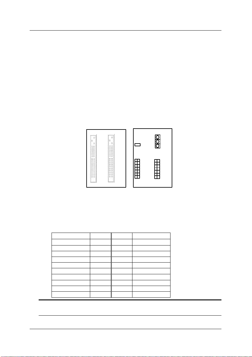
4.1.3 PCB Drawing
1
2
3 4 5
6
7 8 1
2
3 4 5
6
7 8
CN4
6
7
4.1.4 Specifications
J1
5
4
3
2
sys
1
sys
1
2
3
4
5
7
6
u Compliant to CompactPCI PICMG 2.0 R2.1 specifications
u Standard 3U form factor
u Four power input connectors: ATX, PS2, screw terminal, plug-in PSU
input connectors
u V(I/O) selectable from +5V or +3.3V.(default +5V)
u Dimension: 133.35 mm x 243.8 mm x 3.2 mm (3U height, 12-slot
width)
4.1.5 Connectors pin assignments
u P1 & P2 of system slot: Standard 64-bit CompactPCI specifications of
the PICMG 2.0 R2.1 specifications
u P1 & P2 of I/O slot: Standard 64-bit CompactPCI specifications of the
PICMG 2.0 R2.1 specifications
Backplane • 29
Page 40
u CN1: Standard ATX DC Power input connector
Signal Pin No. Pin No.
+3.3V 1 11 +3.3V
+3.3V 2 12 -12V
GND 3 13 GND
+5V 4 14 PS_ON
GND 5 15 GND
+5V 6 16 GND
GND 7 17 GND
PWR_OK 8* 18 -5V
+5V SB 9* 19 +5V Sense
+12V 10 20 +5V
u CN2: Standard PS2 DC Power input connector
u CN3: General Purpose screw terminals
CN3
Pin # Name
1 FAL#
2 DEG#
3 -12V
4 +12V
5 GND
6 +5V
7 V(I/O)
8 +3.3V
9 GND
10 +5V
Signal
u J1: Compliant the 31-pin CompactPCI power supply interface standard
of the PICMG 2.11. (Note: This connector is only available on the -
P version)
u CN5: AC Input terminals for the plug-in power supply unit on J1.
(Note: This connector is only available on the -P version)
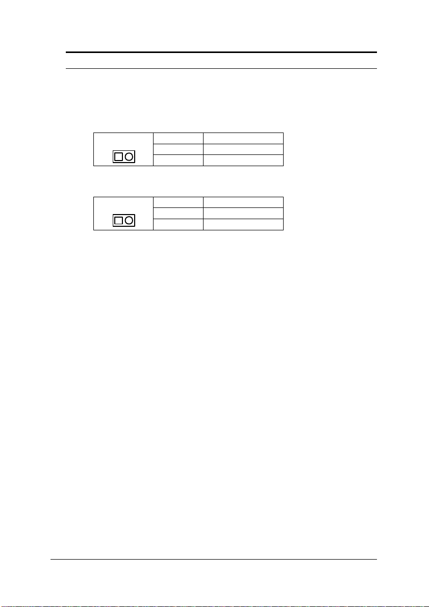
u JP1: DC power inhibit signal, it is for inhibit the ATX PSU. This
connector is used for power-on switch which connect to the pin #14 of
CN3. When the system is using PS2 power supply, the pin 1 and pin
2 must be shorted.
JP1
u CN4: Power Managing Signals, the signals are from the CompactPCI
power connector J1. The pin definitions are as following.
30 • Backplane
Pin # Name
1 PS_ON
2 GND
Page 41

Signal Pin No. Pin No. Signal
GND 1 2 +5V
GND 3 4 DEG#
GND 5 6 FAL#
GND 7 8 INH#
GND 9 10 PRST#
GND 11 12 +5V
GND 13 14 +12V
Please note that to short the pin #7 and pin #8 can disable the DC power
output from CN2 CompactPCI power interface.
Backplane • 31
Page 42

1
2
3 4 5
6
7 8 1
2
3 4 5
6
7 8
4.2 cBP-3100 Series
The cBP-3100 series products are with the same PCBs as the cBP-3400
series products. The only difference is that the P2 of the I/O slots are
removed for cost reduction. All the other features are exactly the same as
the cBP-3400 series products.
6
5
4
7
3
2
sys
1
sys
1
2
3
4
J1
5
7
6
32 • Backplane
Page 43

4.3 cBP-3200 Series
4.3.1 Features
u Compliant to CompactPCI PICMG 2.0 R2.1 specifications
u Support standard 3U form factor
u 32-bit CompactPCI bus on P1, support 7-bus mastering I/O slots
u Optional P2 with rear I/O capability
u Support ATX and screw terminals for DC power input connectors
u V(I/O) selectable from +5V or +3.3V.
u 10 layers PCB for accurate impedance control
u Dimension: 133.35 mm x 182.0 mm x 3.2 mm (3U height, 9-slot width)
4.3.2 Products List
• cBP-3208: 8-slot, 3U 64-bit CompactPCI backplane
• cBP-3206: 6-slot, 3U 64-bit CompactPCI backplane
• cBP-3204: 4-slot, 3U 64-bit CompactPCI backplane
• cBP-3208R: 8-slot, 3U 64-bit CompactPCI backplane with rear I/O
• cBP-3206R: 6-slot, 3U 64-bit CompactPCI backplane with rear I/O
• cBP-3204R: 4-slot, 3U 64-bit CompactPCI backplane with rear I/O
Backplane • 33
Page 44

1
1
2
3 4 5
6
7 8
2
3 4 5
6
7 8
4.3.3 PCB Drawing
cBP-3208:
Front view
Rear view
7
6
Rear I/O
sys
Rear I/O
5
4
3
2
sys
1
R
1
2
3
4
5
7
6
34 • Backplane
Page 45

cBP-3208R:with P2 rear I/O
1
2
3 4 5
6
7 8 1
2
3 4 5
6
7 8
Front view
Rear I/O Rear I/O
6
7
Rear I/O Rear I/O Rear I/O
Rear I/O
5
4
Rear view
sys
4.3.4 Connectors pin assignments
1
2
3
Rear I/O Rear I/O
2
1
sys
3
4
5
7
6
u P1 & P2 of system slot: Standard 32-bit CompactPCI specifications of
the PICMG 2.0 R2.1 specifications
u P1 of I/O slot: Standard 32-bit CompactPCI specifications of the
PICMG 2.0 R2.1 specifications
u P2 of I/O slot: reserved for rear I/O applications. The P2 connectors
are installed only on the cPCI-3208R, 3206R and 3204R versions
u CN1 and CN2: ATX-like DC Power input connectors
Backplane • 35
Page 46

Signal Pin No. Pin No.
+3.3V 1 11 +3.3V
+3.3V 2 12 -12V
GND 3 13 GND
+5V 4 14 INH#
GND 5 15 GND
+5V 6 16 +5V SenseGND 7 17 GND
FAL# 8* 18* JP7
DEG# 9* 19 +5V Sense+
+12V 10 20 +5V
u General Purpose screw terminals
Note: that the V(I/O) must be shorted to either +3.3V or +5V. The default
factory setting is to shorted at +5V.
Position
(from top to bottom)
1 +3.3V
2 V(I/O)
3 +5V
4 GND
5 +12V
6 -12V
Signal
Name
u JP8 INH#: DC power inhibit signal
It is for inhibiting the ATX power supply. This connector is used for
power-on switch.
JP8
u JP9 RST#: System reset signal
JP9
u JP10 FAL#: Power supply fail input
JP10
36 • Backplane
Pin # Name
1 INH#
2 GND
Pin # Name
1 RST#
2 GND
Pin # Name
1 FAL#
2 GND
Page 47

u JP7 +12V Sense: +12V Sense Jumper
JP7
When the normal ATX power supply is used, the pin #18 of CN1/CN2 is
with –5V power, please let this jumper open.
When 31-pin CompactPCI power supply is used, this pin is not used and this
jumper should be left open.
When 47-pin CompactPCI power supply is used, the +12V sense is usable,
therefore, the jumper can be shorted to provide this signal.
Pin # Name
1 From pin #18 of CN1/CN2
2 Connect to +12V Sense
Backplane • 37
Page 48

4.4 cBP-3052E Backplane
4.4.1 Specifications
u Compliant with 31-pin CompactPCI power standard of PICMG 2.11
u Support two 3U redundant power supply unit
u With external AC power input screw terminal
u With two ATX DC output connectors
u Dimension: 133.35 mm x 81.0 mm x 3.2 mm (3U height, 4-slot width)
4.4.2 PCB Drawing
Front view
Rear view
4.4.4 Connectors pin assignments
u J1 & J2: Standard 31-pin CompactPCI power supply sockets,
compliant with PICMG 2.11 specifications
u CN1, CN2: Two identical ATX-like power output connectors
Signal Pin No. Pin No.
+3.3V 1 11 +3.3V
+3.3V 2 12 -12V
GND 3 13 GND
+5V 4 14 INH#
GND 5 15 GND
+5V 6 16 5V SenseGND 7 17 GND
FAL# 8 18 N/C
DEG# 9 19 +5V Sense+
+12V 10 20 +5V
38 • Backplane
Signal
Page 49

Note: Pin #8, #9, and #18 are not standard ATX power definition.
u CN5: Screw terminals for external AC input power lines
u CN7: Screw terminals for GND (CN8, CN9, CN10 are not installed.)
u CN13: Screw terminals for +5V (CN14 is not installed)
u CN15: Screw terminal for +12V
u CN16: Screw terminal for -12V is not installed.
u CN11, CN12: Screw terminals for +3.3V are not installed
Backplane • 39
Page 50

4.5 cBP-3051
4.5.1 Specifications
u Compliant with 31-pin CompactPCI power standard of PICMG 2.11
u Support one 3U plug-in power supply unit
u With external AC power input screw terminal
u With one ATX DC output connectors
4.5.2 PCB Drawing
Front view
Rear view
4.5.3 Connectors pin assignments
u J1: Standard 31-pin CompactPCI power supply sockets, compliant
with PICMG 2.11 specifications
u CN1: ATX-like power output connector
Signal Pin No. Pin No.
+3.3V 1 11 +3.3V
+3.3V 2 12 -12V
GND 3 13 GND
+5V 4 14 INH#
GND 5 15 GND
+5V 6 16 5V SenseGND 7 17 GND
FAL# 8* 18* N/C
DEG# 9* 19 +5V Sense+
+12V 10 20 +5V
40 • Backplane
Signal
Page 51
Note : Pin #8, #9, and #18 are not standard ATX power definition.
u CN5: AC power lines (include AC LINE, AC NEUTRAL, Chassis GND)
u J4 INH#: DC power inhibit signal
It is for inhibiting the ATX DC power supply output. This connector can
be used for power-on switch.
J4
u J3 ISH: +5V current sharing signal, this connector is used only when
more than two cBP-3051 backplanes are used in one system.
J4
Pin # Name
1 INH#
2 GND
Pin # Name
1 ISH
2 GND
Backplane • 41
Page 52
4.6 cBP-3062 Backplane
4.6.1 Specifications
u Compliant with 47-pin CompactPCI power standard of PICMG 2.11
u Support two 3U redundant power supply unit
u With external AC power input screw terminal
u With two ATX DC output connectors
u Dimension: 133.35 mm x 81.0 mm x 3.2 mm (3U height, 4-slot width)
4.6.2 PCB Drawing
Front view
Rear view
4.6.3 Connectors pin assignments
u CN101 & CN102: Standard 47-pin CompactPCI power supply sockets,
compliant with PICMG 2.11 specifications
u CN103: ATX-like power output connectors
Signal Pin No. Pin No.
V2SENSE 1 11 V2
V2 2 12 V4
GND 3 13 GND
V1 4 14 INH#
GND 5 15 GND
V1 6 16 SRTN
GND 7 17 GND
FAL#1 8* 18* V3SENSE
DEG#1 9* 19 V1SENSE
V3 10 20 V1
Note : 1. Pin #8, #9, and #18 are not standard ATX power definition.
2. V1=+5V; V2= 3.3V; V3 = +12V; V4=-12V
42 • Backplane
Signal
Page 53
u CN104 extended connector for power sharing
Signal Pin No. Pin No.
Signal
V2SENSE 1 11 V2
V2 2 12 V4
GND 3 13 GND
V1 4 14 INH#
GND 5 15 GND
V1 6 16 SRTN
GND 7 17 GND
FAL#2 8* 18* V3SENSE
DEG#2 9* 19 V1SENSE
V3 10 20 V1
Note: 1. Pin #8, #9, and #18 are not standard ATX power definition.
2. V1=+5V; V2= 3.3V; V3 = +12V; V4=-12V
u CN105 INH#: DC power output inhibit signal. It is for inhibiting the DC
power supply. This connector can be used for power-on switch.
CN105
Pin # Name
1 INH#
2
GND
u CN107: Screw terminals for external AC input power lines
u CN106: Current sharing connector, this connector is used only when
multiple power backplane is used in the same time.
Signal Pin No. Pin No.
Signal
V1SENSE 1 2 V3SENSE
GND 3 4 V2SENSE
GA2#2 5 6 GA2#1
GA1#2 7 8 GA1#1
GA0#2 9 10 GA0#1
N/C 11 12 N/C
Backplane • 43
Page 54
5
LCD Kit
5.1 Features
u High Brightness 6.4 inches TFT LCD
u Modular design for easy mounting on any 3U CompactPCI Chassis
u Integrated with back light inverter
u Two back-light lamps with 15000 hours long life time
u Optional touch screen with internal RS-232 interface
5.2 Mechanical Drawing
44 • LCD Kit
Page 55

5.3 Specifications
u Dimension: 3U height x 10-slot (40HP) width
u Screen Size: 6.4 inches (diagonal)
u Resolution: 640 x 480 x 18-bit colors (262,144 colors)
u Pixel pitch: 0.203 mm x 0.203 mm
u High brightness 300 cd/m2
u Lamp life time: 15,000 hours @ 25°C
u Integrated with back light inverter
u Power requirement:
• 5V @ 6.0 W (for LCD panel)
• +12V @ 300 mA x 2 (for two backlight inverters)
LCD Kit • 45
Page 56
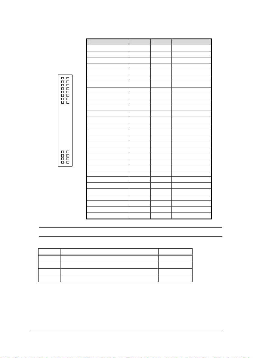
5.4 Connectors Pin Assignment
LCD Signal Connector on the LCD
Pin # Symbol Function Pin # Symbol Function
1 GND Ground 17 G4 Green Data Signal
2 CLK
3 Hsync Horizontal Sync Signal 19 GND Ground
4 Vsync Vertical Sync Signal 20 B0 Blue Data Signal
5 GND Ground 21 B1 Blue Data Signal
6 R0 Red Data Signal 22 B2 Blue Data Signal
7 R1 Red Data Signal 23 B3 Blue Data Signal
8 R2 Red Data Signal 24 B4 Blue Data Signal
9 R3 Red Data Signal 25 B5 Blue Data Signal
10 R4 Red Data Signal 26 GND Ground
11 R5 Red Data Signal 27 DENB
12 GND Ground 28 VCC DC 5V power supply
13 G0 Green Data Signal 29 VCC DC 5V power supply
14 G1 Green Data Signal 30 R/L
15 G2 Green Data Signal 31 U/D Vertical image shift select
16 G3 Green Data Signal --
LCD Signal Extension Connector for cPCI-8215
Signal Pin # Pin # Signal
+12V 1 2 +12V
GND 3 4 GND
VDD 5 6 VDD
ENVEE 7 8 GND
P0 9 10 P1
P2 11 12 P3
P4 13 14 P5
P6 15 16 P7
P8 17 18 P9
P10 19 20 P11
P12 21 22 P13
P14 23 24 P15
P16 25 26 P17
P18 (N/C) 27 28 P19 (N/C)
P20 (N/C) 29 30 P21 (N/C)
P22 (N/C) 31 32 P23 (N/C)
GND 33 34 GND
CLk 35 36 FLM
M 37 38 LP
GND 39 40 EN_BKL
GND 41 42 ENVDD
VDD 43 44 VDD
Clock signal for sampling
image digital data
18 G5 Green Data Signal
Signal to set horizontal
display position
Horizontal image shift
select
46 • LCD Kit
Page 57
LCD Signal Extension Connector for cPCI-8217
58
2
Signal Name Pin # Pin # Signal Name
+12V 1 2 +12V
GND 3 4 GND
+5V 5 6 +5V
ENPVEE 7 8 GND
PD0 9 10 PD1
57 PD2 11 12 PD3
PD4 13 14 PD5
PD6 15 16 PD7
PD8 17 18 PD9
PD10 19 20 PD11
PD12 21 22 PD13
PD14 23 24 PD15
PD16 25 26 PD17
PD18 (N/C) 27 28 PD19 (N/C)
PD20 (N/C) 29 30 PD21 (N/C)
PD22 (N/C) 31 32 PD23 (N/C)
GND 33 34 GND
SHFCLK 35 36 FLM
1
GND 41 42 ENA VDD
VCC 43 44 +5V
NC 45 46 NC
PD26 (N/C) 49 50 PD27 (N/C)
PD28 (N/C) 51 52 PD29 (N/C)
PD30 (N/C) 53 54 PD31 (N/C)
PD32 (N/C) 55 56 PD33 (N/C)
PD34 (N/C) 57 58 PD35 (N/C)
PD24 (N/C) 47 48 PD25 (N/C)
M 37 38 LP
GND 39 40 ENABKL
Note: Only 44 pins are used. Pin #45 to pin #58 are no used.
Power and control connector for the backlight inverter
Pin # Name Color
1 +12V Yellow
2 Power On (default connect to +5V)
3
GND Black
4 VR (default connect to GND)
Red
Black
LCD Kit • 47
Page 58

6
cPCIS-2000 Sub-systems
The following sub-system’s configuration will be listed in this chapter.
Sub-systems: (Single System with LCD)
• cPCIS-2150: 3U CompactPCI Platform with LCD and Off-the-Shelf
ATX PSU
• cPCIS-2151: 3U CompactPCI Platform with LCD and Universal AC
PSU
• cPCIS-2152: 3U CompactPCI Platform with LCD and Dual
Redundant AC PSU
Sub-systems: (Single System without LCD)
• cPCIS-2100: 3U CompactPCI Platform with Off-the-Shelf ATX PSU
• cPCIS-2102: 3U CompactPCI Platform with Dual Redundant AC
PSU
48 • cPCIS-2000 Series Sub-systems
Page 59

6.1 cPCIS-2150 Series
• cPCIS-2150 is without rear I/O connectors
• cPCIS-2150R is with rear I/O connectors
6.1.1 Features
• Standard 19” 3U CompactPCI form factor, 4U in height
• Attached high brightness 6.4” TFT LCD for user interface display
• Attached Auto-switched off-the-shelf 280W ATX power supply
• Using cBP-3208 backplane with 32-bit CompactPCI bus
• Accept 7 I/O slots and one system slot
• Side handle design for portable instrument
• Two built-in 50 CFM fans for self-cooling system
• Removable fans and air-filter
• Suitable for both rack-mount and desktop applications
• Comprehensive EMC shielding
• cPCIS-2150R is equipped with cBP-3208R and rear I/O card guides
for rear I/O applications
6.1.2 Configurations
u Chassis: cPCIS-2000A
u Backplane:
• cBP-3208 is for 32-bit CompactPCI bus without rear I/O connectors
• cBP-3208R is for 32-bit CompactPCI bus with rear I/O connectors
u Power Supply: 280W ATX power supply is installed with cPCI-PSF
u LCD module: cPCI-LCD
u I/O slots configuration:
• 10-slot is installed with high brightness 6.4” TFT LCD
• 7-slot for I/O module
• 3-slot for system module
• 1-slot spared
• cPCI-PSF Power supply frame is installed behind the LCD
• An extra LCD controller card (cPCI-8215 or 8217) should be
installed
cPCIS-2000 Series Sub-systems • 49
Page 60

6.1.3 Ordering Options
To complete the system to work, you should order an optional LCD
controller card:
u cPCI-8215: LCD controller card with C&T69000 (embedded 2MB RAM)
u cPCI-8217: LCD controller card with SMI chipset (embedded 4MB
RAM)
The slot-panels with EMC gasket for the front or rear I/O cards are optional
and not installed with this sub-system.
u cPCI-SP3E: 3U slot-panel with EMC gasket for both front I/O or rear
I/O
50 • cPCIS-2000 Series Sub-systems
Page 61

6.2 cPCIS-2151 Series
6.2.1 Features
• Standard 19” 3U CompactPCI form factor, 4U in height
• Attached high brightness 6.4” TFT LCD for user interface display
• Attached 175W Universal AC input power supply
• Using cBP-3108P backplane with 32-bit CompactPCI bus
• Accept 6 I/O slots due to the available front space
• Side handle design for portable instrument
• Two built-in 50 CFM fans for self-cooling system
• Removable fans and air-filter
• Suitable for both rack-mount and desktop applications
• Comprehensive EMC shielding
6.2.2 Configurations
u Chassis: cPCIS-2000A
u Backplane: cBP-3108P for 32-bit CompactPCI bus
u Power Supply: Installed 175W power supply cPS-150R
u LCD module: cPCI-LCD
u I/O slots configuration:
• 10-slot is installed with high brightness 6.4” TFT LCD
• 6-slot for I/O module
• 3-slot for system module
• 2-slot is installed with single 175W cPS-150R PSU
• An extra LCD controller card (cPCI-8215 or 8217) should be
installed
6.2.3 Ordering Options
To complete the system to work, you should order an optional LCD
controller card:
u cPCI-8215: LCD controller card with C&T69000 (embedded 2MB RAM)
u cPCI-8217: LCD controller card with SMI chipset (embedded 4MB
RAM)
cPCIS-2000 Series Sub-systems • 51
Page 62

The slot-panels with EMC gasket for the front or rear I/O cards are
optional and not installed with this sub-system.
u cPCI-SP3E: 3U slot-panel with EMC gasket for both front I/O or rear
I/O
52 • cPCIS-2000 Series Sub-systems
Page 63

6.3 cPCIS-2100 Series
• cPCIS-2100 is without rear I/O connectors
• cPCIS-2100R is with rear I/O connectors
6.3.1 Features
• Standard 19” 3U CompactPCI form factor, 4U in height
• Optional auto-switched off-the-shelf 280W ATX power supply
• Using cBP-3208 backplane with 32-bit CompactPCI bus
• Accept 7 I/O slots and one system slot
• Side handle design for portable instrument
• Two built-in 50 CFM fans for self-cooling system
• Removable fans and air-filter
• Suitable for both rack-mount and desktop applications
• Comprehensive EMC shielding
• cPCIS-2100R is equipped with cBP-3208R and rear I/O card guides
for rear I/O applications
6.3.2 Configurations
u Chassis: cPCIS-2000A
u Backplane:
• cBP-3208 is for 32-bit CompactPCI bus without rear I/O connectors
• cBP-3208R is for 32-bit CompactPCI bus with rear I/O connectors
u Power Supply: installed with cPCIS-PSF kit, the power supply is
optional.
u LCD module: cPCI-LCD
u I/O slots configuration:
• 7-slot for I/O module
• 3-slot for system module
• 2-slot spared
• 9-slot for cPCI-PSF is installed on the rear panel
cPCIS-2000 Series Sub-systems • 53
Page 64

6.3.3 Ordering Options
To complete the system to work, you should order an optional ATX power
supply:
u APS-925AX: 280W Auto-switched AC input ATX power supply
You can also fit any standard PS2 sized power supply into the slotpanels with EMC gasket for the front or rear I/O cards are optional and
not installed with this sub-system.
u cPCI-SP3E: 3U slot-panel with EMC gasket for both front I/O or rear
I/O
54 • cPCIS-2000 Series Sub-systems
Page 65

6.4 cPCIS-2102 Series
6.4.1 Features
• Standard 19” 3U CompactPCI form factor, 4U in height
• Attached Two cPS-150R for Universal AC redundant power supply
• Using cBP-3208P backplane with 32-bit CompactPCI bus
• Accept 7 I/O slots due to the available front space
• Side handle design for portable instrument
• Two built-in 50 CFM fans for self-cooling system
• Removable fans and air-filter
• Suitable for both rack-mount and desktop applications
• Comprehensive EMC shielding
• cPCIS-2102R is equipped with cBP-3208R and rear I/O card guides
for rear I/O applications
6.4.2 Configurations
u Chassis: cPCIS-2000A
u Backplane:
• cBP-3208 is for 32-bit CompactPCI bus without rear I/O connectors
• cBP-3208R is for 32-bit CompactPCI bus with rear I/O connectors
• cBP-3052 backplane for dual redundant power supply
u Power Supply: Installed two 175W redundant power supply cPS-150R
u I/O slots configuration:
• 7-slot for I/O module
• 3-slot for system module
• 4-slot is installed with two 175W cPS-150R PSU
• 7-slot spared
6.4.3 Ordering Options
You may specify to use cPS-175 series power supply with cBP-3061
backplane.
The slot-panels with EMC gasket for the front or rear I/O cards are optional
and not installed with this sub-system.
cPCIS-2000 Series Sub-systems • 55
Page 66

u cPCI-SP3E: 3U slot-panel with EMC gasket for both front I/O or rear
I/O
56 • cPCIS-2000 Series Sub-systems
Page 67

6.5 cPCIS-2152 Series
6.5.1 Features
• Standard 19” 3U CompactPCI form factor, 4U in height
• Attached high brightness 6.4” TFT LCD for user interface display
• Attached Two cPS-150R for Universal AC redundant power supply
• Using cBP-3206 backplane with 32-bit CompactPCI bus
• Accept 5 I/O slots due to the available front space
• Side handle design for portable instrument
• Two built-in 50 CFM fans for self-cooling system
• Removable fans and air-filter
• Suitable for both rack-mount and desktop applications
• Comprehensive EMC shielding
• cPCIS-2152R is equipped with cBP-3206R and rear I/O card guides
for rear I/O applications
6.5.2 Configuration
u Chassis: cPCIS-2000A
u Backplane:
• cBP-3206 for 32-bit CompactPCI bus without rear I/O
• cBP-3206R for 32-bit CompactPCI bus with rear I/O
• cBP-3052 for redundant power supply
u Power Supply: Installed two 175W redundant power supply cPS-150R
u I/O slots configuration:
• 10-slot is installed with high brightness 6.4” TFT LCD
• 4-slot for I/O module
• 3-slot for system module
• 4-slot is installed with two 175W cPS-150R PSU
6.5.3 Ordering Options
To complete the system to work, you should order an optional LCD controller
card:
u cPCI-8215: LCD controller card with C&T69000 (embedded 2MB RAM)
cPCIS-2000 Series Sub-systems • 57
Page 68

u cPCI-8217: LCD controller card with SMI chipset (embedded 4MB
RAM)
You may specify to use cPS-175 series power supply with cBP-3061
backplane.
The slot-panels with EMC gasket for the front or rear I/O cards are optional
and not installed with this sub-system.
u cPCI-SP3E: 3U slot-panel with EMC gasket for both front I/O or rear
I/O
58 • cPCIS-2000 Series Sub-systems
Page 69

7
cPCIS-1000 Sub-systems
The following sub-system’s configuration will be listed in this chapter.
Sub-systems: (Single System with LCD)
• cPCIS-1151: 3U CompactPCI Platform with LCD and Universal AC
PSU
Sub-systems: (Single System without LCD)
• cPCIS-1100: 3U CompactPCI Platform with Off-the-Shelf ATX PSU
Sub-systems: (Dual System)
• cPCIS-1250: 3U CompactPCI Platform with Dual System
cPCIS-1000 Series Sub-systems • 59
Page 70

7.1 cPCIS-1151
7.1.1 Features
• Standard 19” 3U CompactPCI form factor, 3U in height
• Attached high brightness 6.4” TFT LCD for user interface display
• Attached 175W Universal AC input power supply
• Using cBP-3108P backplane with 32-bit CompactPCI bus
• Accept 5 I/O slots due to the available front space
• Comprehensive EMC shielding
7.1.2 Configurations
u Chassis: cPCIS-1000
u Backplane: cBP-3106P for 32-bit CompactPCI bus
u Power Supply: Installed 175W power supply cPS-150R
u LCD module: cPCI-LCD
u I/O slots configuration:
• 10-slot is installed with high brightness 6.4” TFT LCD
• 5-slot for I/O module
• 3-slot for system module
• 2-slot is installed with single 175W cPS-150R PSU
• 1-slot for power switch
• An extra LCD controller card (cPCI-8215 or 8217) should be
installed
7.1.3 Ordering Options
To complete the system to work, you should order an optional LCD
controller card:
u cPCI-8215: LCD controller card with C&T69000 and 2MB RAM
u cPCI-8217: LCD controller card with SMI chipset and 8MB RAM
The slot-panels with EMC gasket for the front or rear I/O cards are optional
and not installed with this sub-system.
u cPCI-SP3E: 3U slot-panel with EMC gasket for both front I/O or rear
I/O
60 • cPCIS-1000 Series Sub-systems
Page 71

7.2 cPCIS-1100 Series
• cPCIS-1100 is without rear I/O connectors
• cPCIS-1100R is with rear I/O connectors
7.2.1 Features
• Standard 19” 3U CompactPCI form factor, 3U in height
• Optional PS2-sized ATX power supply
• Using cBP-3208 backplane with 32-bit CompactPCI bus
• Accept 7 I/O slots and one system slot
• Comprehensive EMC shielding
• cPCIS-1100R is equipped with cBP-3208R and rear I/O card guides
for rear I/O applications
7.2.2 Configurations
u Chassis: cPCIS-1000
u Backplane:
• cBP-3208 is for 32-bit CompactPCI bus without rear I/O connectors
• cBP-3208R is for 32-bit CompactPCI bus with rear I/O connectors
u Power Supply: installed with cPCIS-PSF kit, the power supply is
optional
u LCD module: cPCI-LCD
u I/O slots configuration:
• 7-slot for I/O module
• 3-slot for system module
• 1-slot spared
• 1-slot for power switch
• 9-slot for cPCI-PSF is installed on the rear panel
7.2.3 Ordering Options
To complete the system to work, you should order an optional ATX power
supply:
u APS-925AX: 280W Auto-switched AC input ATX power supply
cPCIS-1000 Series Sub-systems • 61
Page 72

You can also fit any standard PS2 sized power supply into the controller.
The slot-panels with EMC gasket for the front or rear I/O cards are optional
and not installed with this sub-system.
u cPCI-SP3E: 3U slot-panel with EMC gasket for both front I/O or rear
I/O
62 • cPCIS-1000 Series Sub-systems
Page 73

7.3 cPCIS-1250
7.3.1 Features
• Standard 19” 3U CompactPCI form factor, 3U in height
• Dual systems in one system
• Using cBP-3106P backplane with 32-bit CompactPCI bus for both
system
• Accept 5 I/O slots on each system
• Comprehensive EMC shielding
7.3.2 Configurations
u Chassis: cPCIS-1000
u Backplane: Two cBP-3106P backplanes are for 32-bit CompactPCI
bus without rear I/O connectors
u Power Supply: installed with 175W power supply
u LCD module: cPCI-LCD
u I/O slots configuration:
• 1-slot for power switch
System #1
• 5-slot for I/O module
• 3-slot for system module
• 2-slot for plug-in power supply
System # 2
• 5-slot for I/O module
• 3-slot for system module
• 2-slot for plug-in power supply
7.3.3 Ordering Options
The slot-panels with EMC gasket for the front or rear I/O cards are
optional and not installed with this sub-system.
u cPCI-SP3E: 3U slot-panel with EMC gasket for both front I/O or rear
I/O
cPCIS-1000 Series Sub-systems • 63
Page 74

Product Warranty/Service
Seller warrants that equipment furnished will be free form defects in material
and workmanship for a period of one year from the confirmed date of
purchase of the original buyer and that upon written notice of any such defect,
Seller will, at its option, repair or replace the defective item under the terms of
this warranty, subject to the provisions and specific exclusions listed herein.
This warranty shall not apply to equipment that has been previously repaired
or altered outside our plant in any way as to, in the judgment of the
manufacturer, affect its reliability. Nor will it apply if the equipment has been
used in a manner exceeding its specifications or if the serial number has
been removed.
Seller does not assume any liability for consequential damages as a result
from our product uses, and in any event our liability shall not exceed the
original selling price of the equipment.
The equipment warranty shall constitute the sole and exclusive remedy of
any Buyer of Seller equipment and the sole and exclusive liability of the
Seller, its successors or assigns, in connection with equipment purchased
and in lieu of all other warranties expressed implied or statutory, including,
but not limited to, any implied warranty of merchant ability or fitness and all
other obligations or liabilities of seller, its successors or assigns.
The equipment must be returned postage-prepaid. Package it securely and
insure it. You will be charged for parts and labor if you lack proof of date of
purchase, or if the warranty period is expired.
64 • Product Warranty and Service
 Loading...