

Page 1
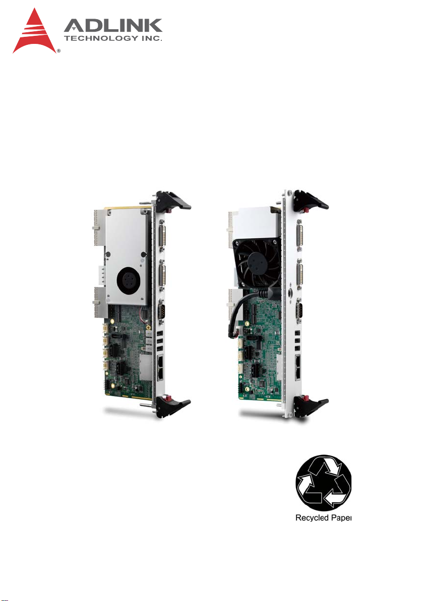
cPCI-R6700
6U CompactPCI® Rear Transition Module
with ATI Radeon™ E4690 GPU
User’s Manual
Manual Rev.: 2.00
Revision Date: November 2, 2012
Part No: 50-15084-1000
Advance Technologies; Automate the World.
Page 2

Revision History
Revision Release Date Description of Change(s)
2.00 2012/11/02 Initial release
ii Revision History
Page 3

cPCI-R6700
Preface
Copyright 2012 ADLINK Technology, Inc.
This document contains proprietary infor mation protected by copyright. All rights are reserved. No part of this manual may be reproduced by any mechanical, electronic, or other means in any form
without prior written permission of the manufacturer.
Disclaimer
The information in this document is subject to change without prior
notice in order to improve reliability, design, and function and does
not represent a commitment on the part of the manufa cturer.
In no event will the manufacturer be liable for direct, indirect, special, incidental, or consequential damages arising out of the use or
inability to use the product or documentation, even if advised of
the possibility of such damages.
Environmental Responsibility
ADLINK is committed to fulfill its social responsibility to global
environmental preservation through compliance with the European Union's Restriction of Hazardous Substances (RoHS) directive and Waste Electrical and Electronic Equipment (WEEE)
directive. Environmental protection is a top priority for ADLINK.
We have enforced measures to ensure that our products, manufacturing processes, components, and raw materials have as little
impact on the environment as possible. When products are at their
end of life, our customers are encouraged to dispose of them in
accordance with the product disposal and/or recovery programs
prescribed by their nation or company.
Trademarks
Product names mentioned herein are used for identification purposes only and may be trademarks and/or registered trademarks
of their respective companies.
Preface iii
Page 4

Using this Manual
Audience and Scope
The cPCI-R6700 User’s Manual is intended for hardware
technicians and systems operators with knowledge of installing,
configuring and operating industrial grade computer systems.
Manual Organization
This manual is organized as follows:
Chapter 1, Introduction: Introduces the cPCI-R6700, its features,
block diagrams, and package contents.
Chapter 2, Specifications: Presents detailed specification infor-
mation.
Chapter 3, Board Interfaces: Describes the cPCI-R6700 co nnec-
tors and switches.
Chapter 4, Getting Started: Describes the installation of the
cPCI-R6700 to the system and driver installation.
Chapter 5, VBIOS Update: Provides information on how to
update the cPCI-R6700 VBIOS.
Important Safety Instructions: Presents safety instructions all
users must follow for the proper setup, installation and usage of
equipment and/or software.
Getting Service: Contact information for ADLINK’s worldwide
offices.
iv Preface
Page 5
cPCI-R6700
Conventions
Take note of the following conventions used throughout this
manual to make sure that users perform certain tasks and
instructions properly.
Additional information, aids, and tips that help users perform
tasks.
NOTE:
NOTE:
Information to prevent minor physical injury, component damage, data loss, and/or program corruption when trying to com-
CAUTION:
WARNING:
plete a task.
Information to prevent serious physical injury, component
damage, data loss, and/or program corruption when trying to
complete a specific task.
Preface v
Page 6

This page intentionally left blank.
vi Preface
Page 7

cPCI-R6700
Table of Contents
Revision History...................................................................... ii
Preface.................................................................................... iii
List of Figures........................................................................ ix
List of Tables.......................................................................... xi
1 Introduction ........................................................................ 1
1.1 Overview.............................................................................. 1
1.2 Features............................................................................... 2
1.3 Block Diagram ..................................................................... 3
1.4 Package Contents ............................................................... 4
2 Specifications..................................................................... 5
2.1 cPCI-R6700 General Specifications .................................... 5
2.2 I/O Connectivity ................................................................... 6
2.3 GPU..................................................................................... 6
2.4 Power Consumption ............................ ... ... ... ... .... ... ... ... .... ... 7
3 Board Interfaces................................................................. 9
3.1 cPCI-R6700(D) Assembly Layout........................................ 9
3.2 cPCI-R6700 Board Layout................................................. 10
3.3 Connector Pin Assignments .............................................. 12
3.4 Switch Settings .................................................................. 20
4 Getting Started ................................................................. 23
4.1 Installing a 2.5" SATA Drive............................................... 23
4.2 Auxiliary Power Cord......................................................... 28
4.3 Installing the cPCI-R6700.................................................. 29
4.4 Driver Installation................................................. ... ... ... .... . 30
vii
Page 8

5 VBIOS Update.................................................................... 31
Important Safety Instructions............................................... 33
Getting Service...................................................................... 35
viii
Page 9

cPCI-R6700
List of Figures
Figure 1-1: cPCI-R6700 Functional Block Diagram ...........................3
Figure 2-1: cPCI-R6700 General Specifications ................................5
Figure 3-1: cPCI-R6700(D) Assembly Layout....................................9
Figure 3-2: cPCI-R6700 Board Layout - Component Side............... 10
Figure 3-3: cPCI-R6700(D) Board Layout - Solder Side..................11
List of Figures ix
Page 10

This page intentionally left blank.
xList of Figures
Page 11

cPCI-R6700
List of Tables
Table 2-1: cPCI-R6700(D) I/O Connectivity......................................6
Table 2-2: cPCI-R6700 Power Consumption................................ ... . 7
Table 3-1: DVI-I Connector Pin Definition.......................................12
Table 3-2: CompactPCI J3 Connector Pin Definition...................... 18
Table 3-3: CompactPCI J5 Connector Pin Definition...................... 19
Table 3-4: COM2 Mode Switch Settings.........................................20
Table 3-5: LAN Control Switch Settings..........................................21
List of Tables xi
Page 12

This page intentionally left blank.
xii List of Tables
Page 13

1 Introduction
1.1 Overview
The cPCI-R6700 Series is 6U CompactPCI rear transition module
(RTM) designed for use with ADLINK 6U CompactPCI CPU
blades. The cPCI-R6700 is an RTM equipped with the ATI Radeon™ E4690 graphics processor unit (GPU) to provide additional
graphics performance for embedded applications and supports
comprehensive rear I/O functionality. The Radeon™ E4690 GPU
features an integrated 600 MHz engine clock, 700 MHz memory
clock, 128-bit memory interface and 512MB GDDR3 VRAM. Dual
independent display output is via two DVI-I ports and an onboard
Realtek ALC262 High Definition Audio Codec provides analog
audio output from the audio controller on the CPU blade. The
cPCI-R6700 requires a compatible 6U CompactPCI backplane
with rear I/O support and correctly configured CPU blade.
Two models are available: the cPCI-R6700 (4HP) and
cPCI-R6700D (8HP). The cPCI-R6700 is a 4HP RTM equipped
with two DVI-I ports, two GbE ports, three USB Type A ports, and
one COM port (RS-232/422/485 selectable) on the faceplate.
Onboard I/O includes one 5-pin USB pin header, one 10-pin USB
box header, one 10-pin Mic-in/Line-in/Line-out box header, one
10-pin COM box header (TX/RX only), one 10-pin PS/2 box
header and three SATA 7-pin connectors for external storage
device. The cPCI-R6700D is an 8HP RTM that provides a PS/2
keyboard/mouse Mini-DIN port on the faceplate and space to
mount a 2.5" SATA drive for onboard storage requirements.
For applications requiring reduced power consumption, the graphics engine clock can be changed by VBIOS update. When the
cPCI-R6700 is used with a CPU blade that consumes over 50W of
power or under extended temperature conditions (>60°C), additional power supply must be supplied to the RTM using an auxiliary power cord provided in the package.
cPCI-R6700
Introduction 1
Page 14

1.2 Features
X 6U CompactPCI RTM in 4HP or 8HP width form factor
X Compliant with CompactPCI Specification 2.0, Rev. 3.0
X Compliant with CompactPCI Packet Switching Backplane
Specification PICMG 2.16 Rev. 1.0
X 64-bit/66 MHz CompactPCI interface based on PCI specifica-
tions
X ATI Radeon™ E4690 embedded GPU
X Integrated 128-bit memory interface and 512MB GDDR3
VRAM
X Up to 600MHz engine clock and 700MHz memory clock
X Supports DirectX 10.1 and OpenGL 3.x
X Supports display resolutions up to 3840x2400 per display out-
put
X Engine clock can be changed by VBIOS update
X Realtek ALC262 HD Audio codec
X Two DVI-I ports for dual independent displays
X One DB-9 serial port support RS-232/422/485
X Three USB Type A ports
X Two Gigab it Ethernet ports from CPU board
X One PS/2 keyboard mouse on faceplate (cPCI-R6700D only)
X One 5-pin USB 2.0 pin header and one 10-pin USB 2.0 box
header onboard
X One onboard 10-pin COM box header support RS-232, TX/RX
only
X One onboard 10-pin PS/2 keyboard mouse box header on
cPCI-R6700
X One onboard 10-pin audio box header (Mic-in, Line-in,
Line-out)
X Three SATA 7- pin connectors
X 2.5" drive space on 8HP version (cPCI-R6700D only)
2Introduction
Page 15
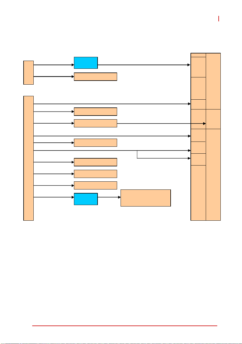
1.3 Block Diagram
r
r
/
r
A
-
cPCI-R6700
rJ5
rJ3
PCIE x4
SATA 0
TX , R X, G ND
PS/2 KB/MS
USB 4/7
USB 5
SATA 2
SATA 1
HD
ATI E4690
SAT A 7-pin connecto
RS-232 10-pin heade
KB/ MS 10-pi n header
USB x2 10-pin header
USB 5-pin header
SAT A 7-pin connecto
SAT A 7-pin connector
ALC262
RS-232/422/485
PS/2 KB/MS
USB 6
LAN x2 (PICMG 2.16)
Mic -i n, Line-out Line-i n,
10-pin header
8/9
DVI-I
DVI-I
DB
LAN
LAN
9
PS/2
KB/MS
L1 L2
Figure 1-1: cPCI-R6700 Functional Block Diagram
Introduction 3
Page 16

1.4 Package Contents
The cPCI-R6700 is packaged with the following components. If
any of the items on the contents list are missing or damaged,
retain the shipping carton and packing material and contact the
dealer for inspection. Please obtain authorization before returning
any product to ADLINK.
X cPCI-R6700 module
X 2.5" drive bracket kit (cPCI-R6700D only)
X Auxiliary power cord (4-pin Molex to 6-pin RTM onboard
connector, 20cm)
X ADLINK All-in-One DVD
X User's manual
This product must be protected from static discharge and
physical shock. Never remove any of the components
CAUTION:
except at a static-free workstation. Use the anti-static bag
shipped with the product when putting the board on a surface. Wear an anti-static wrist strap properly grounded on
one of the system's ESD ground jacks when installing or
servicing system components.
4Introduction
Page 17

cPCI-R6700
2 Specifications
2.1 cPCI-R6700 General Specifications
Standards • CompactPCI® Specification 2.0, Rev. 3.0
• CompactPCI® Packet Switching Backplane Specification
PICMG 2.16 Rev. 1.0
Form Factor • Standard 6U CompactPCI® Rear Transition Module
• Board size: 233.35mm x 80mm
• Single-slot (4HP, 20.32mm) or dual-slot (8HP, 40.64mm)
• CompactPCI® connectors rJ3 and rJ5
GPU • ATI Radeon™ E4690 embedded GPU
• Integrated 128-bit memory interface and 512MB GDDR3
• 600 MHz engine clock and 700 MHz memory clock
• Supports DirectX 10.1 and OpenGL 3.x
• Supports resolutions up to 3840x2400 per display output
• Engine clock changeable by VBIOS update
• PCI Express x4 lane interface
Audio • Realtek ALC262 HD Audio codec
Faceplate I/O • 2x 10/100/1000BASE-T Ethernet ports
• 3x USB 2.0 Ty pe A ports
• 1x DB-9 COM port (RS-232/422/485)
• 2x DVI-I ports from onboard ATI E4690 GPU
• 1x PS/2 Mini-DIN keyboard/mouse (cPCI-R6700D only)
Onboard
Peripherals
OS
Compatibility
Environmental • Operating Temperature: 0 °C to +60 °C
• 3x 7-pin SATA connectors
• 1x RS-232 10-pin box header (Tx, Rx signals only)
• 1x KB/MS 10-pin box header (cPCI-R6700 only)
• 1x USB 10-pin box header (2 ports)
• 1x Mic-in/Line-out 10-pin box header
• 1x USB 5-pin header
• Microsoft Windows XP Professional 32-bit
• Microsoft Windows 7 64-bit
• Microsoft Windows Server 2003 32-bit
• Microsoft Windows Server 2008 64-bit
• Red Hat Enterprise Linux 6.0 64-bit
• Extended Temperature: -20 °C to +70 °C
Figure 2-1: cPCI-R6700 General Specifications
Specifications 5
Page 18

2.2 I/O Connectivity
Function
LAN Y x2 - Y x2 -
USB Y x3 Y x2 Y x3 Y x2
COM Y x1
DVI-I Y x2 - Y x2 -
Serial A TA -Y x3-Y x3
Audio -Y x1-Y x1
KB/MS - Y x1 Y x1 (PS/2) -
2.5” drive space ---Y x1
Table 2-1: cPCI-R6700(D) I/O Connectivity
cPCI-R6700 cPCI-R6700D
Faceplate Board Faceplate Board
Y x1 (RS-232
TX/RX)
Y x1
Y x1 (RS-232
TX/RX)
2.3 GPU
The following sections describe the ATI Radeon E4690 embedded
GPU features and functions.
X Integrated 512MB GDDR3 and 128-bit memory interface
X Fully DirectX 10.1 compliant
X Support for OpenGL® 3.0
X Dual independent display controllers support true 30-bpp
throughout the display pipe
X Support for display resolutions up to 3840x2400 per disp lay
output
X Dual RGB output
X Maximum pixel frequency of 400 MHz for RGB
X Fully compliant with PCI Express Base Specification Rev.
2.0.
X Supports PCI-Express x1, x2, x4, x8, and x16 lane widths.
X Full ACPI 1.0b, OnNow, and IAPC (Instantly Available PC)
power management.
6 Specifications
Page 19

cPCI-R6700
2.4 Power Consumption
The power consumption data of the cPCI-R6700 was measured
using 3D Mark06 at different engine clock frequencies (memory
clock fixed at 700MHz).
Configuration
Test Tool Futuremark® 3DMark06 Professional Edition 1.1.0
CPU Blade ADLINK cPCI-6210 w/ Core™ i7-2710QE
Backplane ADLINK cBP-6402R
Power Supply Sunpower SPX-6500P1
Power Consumption
Clock
Engine
600 MHz
400 MHz
300 MHz
100 MHz
Voltage (V) Current (A) Power (W)
+5 V 4.24 A 21.2 W
+12 V 1.42 A 17.04W
+5 V 3.83 A 19.15 W
+12 V 1.1 A 13.2 W
+5 V 3.3 A 16.5 W
+12 V 1.01 A 12.12 W
+5 V 2.8 A 14 W
+12 V 0.85 A 10.2 W
Total Power
(W)
38.24
32.35
28.62
24.2
Table 2-2: cPCI-R6700 Power Consumption
Due to limited available power from the CompactPCI backplane, it is advised to use the auxiliary power cord provided in
NOTE:
NOTE:
the package to supply additional power when the CPU blade
power consumption exceeds 50W or if used under extended
temperature conditions (>60°C). Please refer to 4.2 Auxiliary
Power Cord on page 28.
Specifications 7
Page 20

This page intentionally left blank.
8 Specifications
Page 21

3 Board Interfaces
This chapter illustrates the board layout, connector pin
assignments, and switch settings to familiarize users with the
cPCI-R6700.
3.1 cPCI-R6700(D) Assembly Layout
Heatsink
Heatsink
Fan
Fan
cPCI-R6700
Drive Bracket
cPCI-R6700 cPCI-R6700D
Figure 3-1: cPCI-R6700(D) Assembly Layout
Board Interfaces 9
Page 22

3.2 cPCI-R6700 Board Layout
rJ5
U1
DVI-I
CN8
rJ3
PS/2
COM1
USB2
HDA
USB1
SW4
SW3
CN3
FAN1
CN2
CN9
CN4
DVI-I
COM2
USB x3
GbE b
GbE a
DVI-I DVI-I connectors HDA Audio box header
CN2/3/4 SATA connectors PS/2 PS/2 KB/MS box header
CN8 Aux. Power connector rJ3/rJ5 cPCI connectors
CN9 SATA power connector SW3/SW4 LAN control switches
COM1 COM box header U1 ATI E4690 GPU
COM2 COM2 connector USB1 USB5 5-pin header
FAN1 Fan power connector USB2 USB4/7 box header
GbE a/b LAN RJ-45 connectors USB x3
USB Type A connectors
(USB6/9/8)
Figure 3-2: cPCI-R6700 Board Layout - Component Side
10 Board Interfaces
Page 23

SW1
SW2
cPCI-R6700
SW1/2 COM2 mode switches
Figure 3-3: cPCI-R6700(D) Board Layout - Solder Side
Board Interfaces 11
Page 24

3.3 Connector Pin Assignments
Faceplate Connectors
DVI-I Connectors
Pin # Signal Pin # Signal
1 TMDS Data2- 16 Hot Plug Detect
2 TMDS Data2+ 17 TMDS Data03 GND 18 TMDS Data0+
4NC19GND
5 NC 20 TMDS Data56 DDC Clock [SCL] 21 TMDS Data5+
7 DDC Data [SDA] 22 TMDS Clock Shield
8 Analog vertical sync 23 TMDS Clock +
9 TMDS Data1- 24 TMDS Clock 10 TMDS Data1+ C1 Analog Red
11 GND C2 Analog Green
12 NC C3 Analog Blue
13 NC C4 Analog Horizontal Sync
14 +5 V Power C5 Analog GND Return
15 GND
Ta bl e 3-1: DVI-I Connector Pin Definition
12 Board Interfaces
Page 25

COM2 RS-232/422/485 Connector
Pin # RS-232 RS-422/485+ RS-485
1 DCD TXD- Data2RXD TXD+ Data+
3 TXD RXD+ --
6
1
4 DTR RXD -5 GND GND GND
5
6 DSR -- -7 RTS -- -8 CTS -- -9 RI -- --
See “COM2 Mode Switches (SW1, SW2)” on page 20.
NOTE:
NOTE:
USB6/9/8 Type A Connectors
cPCI-R6700
Pin # Signal Name
1Vcc
2 USB_D3USB_D+
4GND
Board Interfaces 13
Page 26

GbE a/b RJ-45 Connectors
Pin #
1TX+ LAN_TXP0
2TX- LAN_TXN0
3RX+ LAN_TXP1
4 -- LAN_TXP2
5 -- LAN_TXP2
6RX- LAN_TXN1
7 -- LAN_TXP3
8 -- LAN_TXN3
Network link is not established
or system powered off
10 Mbps
100 Mbps
1000 Mbps
10BASE-T/
100BASE-TX
Status
Active OFF Blinking
Active Green Blinking
Active Amber Blinking
1000BASE-T
Speed LED
(Green/Amber)
OFF OFF
Link OFF ON
Link Green ON
Link Amber ON
81
Speed Activity
Activity LED
(Amber)
PS/2 Keyboard/Mouse Port (cPCI-R6700D only)
Pin # Signal Function
1 KB_DATA Keyboard Data
2 MS_DATA Mouse Data
3 GND Ground
4KM_VCC Power
5 KB_CLK Keyboard Clock
6 MS_CLK Mouse Clock
14 Board Interfaces
Page 27

Onboard Connectors
SATA Connectors (CN2~4)
Pin # Signal
1GND
2TX+
3TX4GND
5RX6RX+
7GND
Auxiliary Power Connector (CN8)
(6-pin, 2.5 mm pitch Wafer)
1
cPCI-R6700
1
7
Pin # Signal
1P12V
2GND
3GND
4P5V
5P5V
6P5V
SATA Powe r Connector (CN9)
Pin # Signal
1P5V
2 P12V
1
Board Interfaces 15
3NC
4GND
5GND
Page 28

COM1 RS-232 Box Header (COM1)
(2x5-pin, 2.0 mm pitch Wafer)
Pin # RS-232 Signal
1NC
2NC
2
3RXD
1
4NC
5TXD
6NC
7NC
8NC
9 IsoGND
10 NC
Fan Power Connector (FAN1)
Pin # Signal
1GND
1
2 P12V
3NC
Audio Box Header (HDA)
(2x5-pin, 2.0 mm pitch Wafer)
Pin # Signal Pin # Signal
2
16 Board Interfaces
1
2 L_OUT_L 1 GND
4 GND 3 L_OUT_R
6L_IN_L5 GND
8 GND 7 L_IN_R
10 MIC_LR 9 GND
Page 29

PS/2 Keyboard/Mouse Box Header (PS/2)
(2x5-pin, 2.0 mm pitch Wafer)
Pin # Signal Pin # Signal
2
1
2 KB_CLK 1 KB_DATA
4MS_CLK3MS_DATA
6GND5KM_VCC
8 GND 7 GND
10 NC 9 GND
USB5 Header (USB1)
(5-Pin, 2.54 mm pitch)
Pin # Signal
1
1+5V
2USB5D3 USB5D+
4GND
5NC
cPCI-R6700
USB 4/7 Box Header (USB2)
(2x5-pin, 2.0 mm pitch Wafer)
Pin # Signal Pin # Signal
2
Board Interfaces 17
1
2 +5V 1 +5V
4 USB4_D- 3 USB7_D6 USB4_D+ 5 USB7_D+
8 GND 7 GND
10 NC 9 Key
Page 30

CompactPCI rJ3 Pin Assignment
Pin Z A B C D E F
19 GND P5V P5V P12V P5V P5V GND
18 GND
17 GND
16 GND
15 GND
14 GND
13 GND
12 GND
11 GND
10 GND
9GND
8GND
7GND
6GND
5 GND GND GND NC GND GND GND
4GND
3GND
2GND
1GND
LAN2_TXP0 (b) LAN2_TXN0 (b) GND LAN2_TXP2 (b) LAN2_TXN2 (b) GND
LAN2_TXP1 (b) LAN2_TXN1 (b) GND LAN2_TXP3 (b) LAN2_TXN3 (b) GND
LAN1_TXP0 (a) LAN1_TXN0 (a) GND LAN1_TXP2 (a) LAN1_TXN2 (a) GND
LAN1_TXP1 (a) LAN1_TXN1 (a) GND LAN1_TXP3 (a) LAN1_TXN3 (a) GND
USB-OC4-L USB-OC5-L USB-OC6-L USB-OC7-L USB-OC8-L GND
USB4P YSB4N GND USB5P USB5N GND
USB6P USB6N GND USB7P USB7N GND
USB8P USB8N GND USB9P USB9N GND
USB-OC9-L NC NC NC NC GND
CTS1-L RI1-L NC NC NC GND
SIN1 SOUT1 DTR1-L DSR1-L RTS1-L GND
COM_TXD COM_RXD DCD1-L NC NC GND
SATA3_RXP0 SATA3_RXN0 GND SATA3_RXP1 SATA3_RXN1 GND
SATA3_TXP0 SATA3_TXN0 GND SATA3_TXP1 SATA3_TXN1 GND
KB_DATA KB_CLK NC MS_DATA MS_CLK GND
HDA_SDIN1 HDA_SDIN2 HDA_SDIN3 HDA_EN-L AUD_RST-L GND
HDA_RST-L HDA_SYNC HDA_BIT_CLK HDA_SDOUT HDA_SDIN0 GND
Table 3-2: CompactPCI J3 Connector Pin Definition
High Definition Audio
Keyboard/Mouse
Serial ATA
Serial port
USB port
Ethernet port
18 Board Interfaces
Page 31

cPCI-R6700
CompactPCI rJ5 Pin Assignment
Pin Z A B C D E F
22 GND P1V8_LAN LAN1_LINK-L (a) LAN1_ACT-L (a) LAN2_LINK-L (b) LAN2_ACT-L (b) GND
21 GND NC NC GND NC NC GND
20 GND NC NC GND NC NC GND
19 GND NC NC NC NC NC GND
18 GND NC NC NC NC NC GND
17 GND NC NC NC NC NC GND
16 GND NC NC NC NC NC GND
15 GND NC NC NC
14 GND NC NC GND
13 GND
12 GND NC NC NC NC NC GND
11 GND NC NC GND NC NC GND
10 GND NC NC GND NC NC GND
9 GND NC NC NC NC NC GND
8 GND NC NC GND NC NC GND
7 GND GND GND BAT_RTM GND GND GND
6GND
5 GND GND GND GND GND GND GND
4GND
3GND
2GND
1GND
LAN1_100-L (a) LAN2_100-L (b) NC LAN2_1G-L (b) LAN1_1G-L (a) GND
PCIE_CLKP PCIE_CLKN GND PLTRST-L NC GND
PCIE_TXP4 PCIE_TXN4 GND PCIE_RXP4 PCIE_RXN4 GND
PCIE_TXP3 PCIE_TXN3 GND PCIE_RXP3 PCIE_RXN3 GND
PCIE_TXP2 PCIE_TXN2 GND PCIE_RXP2 PCIE_RXN2 GND
PCIE_TXP1 PCIE_TXN1 GND PCIE_RXP1 PCIE_RXN1 GND
SATA_RXP0 SATA_RXN0 GND
SATA_TXP0 SATA_TXN0 GND
Table 3-3: CompactPCI J5 Connector Pin Definition
PCI-Express x4
Serial ATA
Ethernet port
Board Interfaces 19
Page 32

3.4 Switch Settings
2
COM2 Mode Switches (SW1, SW2)
The COM2 port on the cPCI-R6700 faceplate supports
RS-232/422/485 modes. Switches SW1 and SW2 can be used
to configure the COM2 port to the desired mode using the settings shown below (set to RS-232 by default).
1
ON
1
ON
2
3
4
5
6 7 8
SW1 SW2
3
4
5 6 7
8
Mode RS-232 (default) RS-422 RS-485
SW1
SW2
1, 4, 6 ON
(all others OFF)
1, 3 ON
(all others OFF)
2, 5, 7 ON
(all others OFF)
2, 4, 5, 6 ON
(all others OFF)
3, 5, 7 ON
(all others OFF)
2, 4, 5, 6 ON
(all others OFF)
T able 3-4: COM2 Mode Switch Settings
20 Board Interfaces
Page 33

cPCI-R6700
2
LAN Control Switches (SW3, SW4)
The cPCI-R6700 can route LAN signals from the CPU blade to
either the PICMG 2.16 backplane or to GbE a/b on the faceplate I/O (but not both simultaneously). Switches SW3 and
SW4 can be used to route the LAN signals (set to faceplate
RJ-45 connectors by default).
1
ON
1
ON
2
3
4
5
6 7 8
SW3 SW4
3
4
5 6 7
8
LAN signals routed to SW3 SW4
PICMG 2.16 Backplane All OFF All OFF
Faceplate RJ-45 connectors
(default)
All ON All ON
Table 3-5: LAN Control Switch Settings
Board Interfaces 21
Page 34

This page intentionally left blank.
22 Board Interfaces
Page 35

4 Getting Started
4.1 Installing a 2.5" SATA Drive
The cPCI-R6700D has space onboard to mount a 2.5" storage
device using the bracket kit provided. The kit includes 4x M3 4mm
screws and 4x M3 6mm screws. Follow the steps below to install a
SATA drive on the RTM.
1. Prepare a 2.5" SATA drive and locate the bracket kit in
the package.
cPCI-R6700
2. Align the bracket with SATA power/signal connectors as
shown and mount the drive onto the bracket. Fasten the
bracket to the drive with two of the M3 4mm screws.
Getting Started 23
Page 36

3. Secure the remaining bracket to the other side of the
drive with the two remaining M3 4mm screws. This unit
will be hereafter referred to as the "drive assembly".
24 Getting Started
Page 37

cPCI-R6700
4. Disconnect the PS/2 cable from the onboard connector
as shown as below.
5. Connect the SATA power connector from the drive
assembly to the onboard shown as below.
Getting Started 25
Page 38

6. Pass the SATA signal cable underneath the PS/2 cable
and connect it to the onboard connector as shown.
7. Reconnect the PS/2 cable to the onboard connector.
26 Getting Started
Page 39

cPCI-R6700
8. Align the standoffs on the drive assembly with the 4
screw holes on the PCB as shown.
9. Secure the drive assembly to the RTM using the 4 M3
6mm screws from the solder side of the board.
Getting Started 27
Page 40

4.2 Auxiliary Power Cord
If required, install the Auxiliary Power Cord included in the package.
Additional power supply must be supplied to the RTM using an
auxiliary power cord when the cPCI-R6700 is used with a CPU
CAUTION:
To CN8 onboard
blade that consumes over 50W of power or under extended
temperature conditions (>60°C).
1. Locate the Auxiliary Power Cord (20 cm) in the package.
connector
2. Connect the 6-pin power connector to the cPCI-R6700
RTM (CN8).
To ATX
power supply
3. After the RTM is installed in the chassis (see “Installing
the cPCI-R6700” on page 29 below), connect either the
male or
28 Getting Started
female 4-pin Molex connector to the power supply.
Page 41

cPCI-R6700
4.3 Installing the cPCI-R6700
The cPCI-R6700 may be installed in an RTM slot of a 6U CompactPCI chassis when mated to a compatible CPU blade. See
the6U RTM Blade-to-RTM Compatibility Guide at
http://www.adlinktech.com/cPCI/CompactPCI-Rear-Transition.html.
These instructions are for reference only. Refer to the user guide
that comes with the chassis for more informatio n.
1. Ensure that the cPCI-R6700 is compatible with the CPU
blade and the backplane prior to installation.
2. If required, ensure that the 2.5" SATA drive, Auxiliary
Power Cord, or other peripheral devices are properly
installed.
3. Remove the black plastic caps securing the retaining
screws to the faceplate.
4. Ensure that the system is powered OFF before proceed-
ing.
5. Select the appropriate slot for the cPCI-R6700 RTM as
determined by your application requirements.
6. Align the module's top and bottom e dges to the chassis
card guides, and then carefully slide the module into the
chassis. A slight resistance may be felt when inserting
the module. If the resistance it too strong, check if there
are bent pins on the backplane or if the board's connector pins are not properly aligned with connectors on the
backplane. Then push the board until it is completely
flush with the chassis
7. Push the ejector handles outwards to secure the module
in place, and then fasten the retaining screws on the
module face plate.
8. If required, connect any cables and peripherals to the
board, and then power ON the chassis.
Getting Started 29
Page 42

4.4 Driver Installation
The cPCI-R6700 drivers can be found on the ADLINK All-In-One
DVD at X:\cPCI-R6700\GPU, or at the ADLINK website
(http://www.adlinktech.com). Driver installation procedures for
Windows® XP are described below.
1. Install the Windows operating system before installing
any driver. Most standard I/O device drivers are installed
during Windows installation.
2. Install the graphics driver by extracting and running the
file issetup.exe from the archive
ATI_Graphics_WinXP_8.660.0.0.zip, located in
X:\cPCI-R6700\GPU\.
3. Install the audio driver by extracting and running the executable file in the archive
Realtek_WDM_Audio_WinXP32_Win2003_v2.21.zip
located in X:\cPCI-R6700\Audio\Windows XP x32 2003\.
We recommend using the drivers provided on the ADLINK
All-in-One DVD or downloaded from the ADLINK website to
ensure compatibility.
30 Getting Started
Page 43

5 VBIOS Update
For thermal considerations, the engine clock of the cPCI-R6700
can be changed by applying a VBIOS update. ADLINK provides
four VBIOS options (100, 300, 40 0, 600 MHz) for use rs to set the
best performance and thermal combination for their application.
The VBIOS updates can be found on the All-In-One DVD at
X:XMC\cPCI-R6700\VBIOS, or downloaded from the ADLINK
website (http://www.adlinktech.com).
The graphics driver must be installed before applying any
VBIOS updates.
NOTE:
NOTE:
Follow the steps below to update the VBIOS.
1. Create a DOS bootable USB flash drive.
2. Extract the contents of the R6700_VBIOS.zip file
located in X:\cPCI-R6700\VBIOS on the All-In-One DVD
or downloaded from the ADLINK website.
3. Copy the files inside the R6700_VBIOS folder to the
root directory of USB flash drive.
cPCI-R6700
4. Boot the system from the USB flash drive.
5. Type the command "xxx" (without the "...") from the root
directory to update the VBIOS, where "xxx" is the
desired engine clock frequency (e.g. “100”, “300”, “400”,
“600”).
VBIOS Update 31
Page 44

This page intentionally left blank.
32 VBIOS Update
Page 45

cPCI-R6700
Important Safety Instructions
For user safety, please read and follow all instructions,
WARNINGS, CAUTIONS, and NOTES marked in this manual
and on the associated equipment before handling/operating the
equipment.
X Read these safety instructions carefully.
X Keep this user’s manual for future reference.
X Read the specifications section of this manual for detailed
information on the operating environment of this equipment.
X When installing/mounting or uninstalling/removing
equipment:
Z Turn off power and u nplug any power cords/cables.
X To avoid electrical shock and/or damage to equipment:
Z Keep equipment away from water or liquid sources;
Z Keep equipment away from high heat or high humidity;
Z Keep equipment properly ventilated (do not block or
cover ventilation openings);
Z Make sure to use recommended voltage and powe r
source settings;
Z Always install and operate equipment near an easily
accessible electrical socket-outlet;
Z Secure the power cord (do not place any obje ct on /ove r
the power cord);
Z Only install/attach and operate equipment on stable
surfaces and/or recommended mountings; and,
Z If the equipment will not be used for long periods of time,
turn off and unplug the equipment from its power source.
Important Safety Instructions 33
Page 46

X Never attempt to fix the equipment. Equipmen t sho u ld on ly
be serviced by qualified personnel.
A Lithium-type battery may be provided for uninterrupted, backup
or emergency power.
Risk of explosion if battery is replaced with one of an incorrect
WARNING:
type. Dispose of used batteries appropriately.
X Equipment must be serviced by authorized technicians
when:
Z The power cord or plug is damaged;
Z Liquid has penetrated the equipment;
Z It has been exposed to high humidity/moisture;
Z It is not functioning or does not function according to the
user’s manual;
Z It has been dropped and/or damaged; and/or,
Z It has an obvious sign of breakage.
34 Important Safety Instructions
Page 47

Getting Service
Contact us should you require any service or assistance.
ADLINK Technology, Inc.
Address: 9F, No.166 Jian Yi Road, Zhonghe District
New Taipei City 235, Taiwan
ᄅקؑխࡉ৬ԫሁ 166 ᇆ 9 ᑔ
Tel: +886-2-8226-5877
Fax: +886-2-8226-5717
Email: service@adlinktech.com
Ampro ADLINK Technology, Inc.
Address: 5215 Hellyer Avenue, #110, San Jose, CA 95138, USA
Tel: +1-408-360-0200
Toll Free: +1-800-966-5200 (USA only)
Fax: +1-408-360-0222
Email: info@adlinktech.com
ADLINK Technology (China) Co., Ltd.
Address: Ϟ⍋Ꮦ⌺ϰᮄᓴ∳催⾥ᡔು㢇䏃 300 ো(201203)
300 Fang Chun Rd., Zhangjiang Hi-Tech Park,
Pudong New Area, Shanghai, 201203 China
Tel: +86-21-5132-8988
Fax: +86-21-5132-3588
Email: market@adlinktech.com
cPCI-R6700
ADLINK Technology Beijing
Address: ࣫ҀᏖ⍋⎔Ϟഄϰ䏃 1 োⲜ߯ࡼ E ᑻ 801 ᅸ(100085)
Tel: +86-10-5885-8666
Fax: +86-10-5885-8626
Email: market@adlinktech.com
ADLINK Technology Shenzhen
Address: ⏅ഇᏖቅ⾥ᡔು催ᮄϗ䘧᭄ᄫᡔᴃು
Tel: +86-755-2643-4858
Fax: +86-755-2664-6353
Email: market@adlinktech.com
LiPPERT ADLINK Technology GmbH
Address: Hans-Thoma-Strasse 11, D-68163, Mannheim, Germany
Tel: +49-621-43214-0
Fax: +49-621 43214-30
Email: emea@adlinktech.com
Rm. 801, Power Creative E, No. 1,
Shang Di East Rd., Beijing, 100085 China
A1 2 ὐ C (518057)
2F, C Block, Bldg. A1, Cyber-Tech Zone, Gao Xin Ave. Sec. 7,
High-Tech Industrial Park S., Shenzhen, 518054 China
Getting Service 35
Page 48

ADLINK Technology, Inc. (French Liaison Office)
Address: 15 rue Emile Baudot, 91300 Massy CEDEX, France
Tel: +33 (0) 1 60 12 35 66
Fax: +33 (0) 1 60 12 35 66
Email: france@adlinktech.com
ADLINK Technology Japan Corporation
Address: ͱ101-0045 ᵅҀ䛑ҷ⬄⼲⬄䤯ފ⬎ 3-7-4
Tel: +81-3-4455-3722
Fax: +81-3-5209-6013
Email: japan@adlinktech.com
ADLINK Technology, Inc. (Korean Liaison Office)
Address: 昢殾柢 昢爎割 昢爎壟 1675-12 微汾瘶捒娯 8猻
Tel: +82-2-2057-0565
Fax: +82-2-2057-0563
Email: korea@adlinktech.com
ADLINK Technology Singapore Pte. Ltd.
Address: 84 Genting Lane #07-02A, Cityneon Design Centre,
Tel: +65-6844-2261
Fax: +65-6844-2263
Email: singapore@adlinktech.com
ADLINK Technology Singapore Pte. Ltd. (Indian Liaison Office)
Address: 1st Floor, #50-56 (Between 16th/17th Cross) Margosa Plaza,
Tel: +91-80-65605817, +91-80-42246107
Fax: +91-80-23464606
Email: india@adlinktech.com
⼲⬄ 374 ɛɳ 4F
KANDA374 Bldg. 4F, 3-7-4 Kanda Kajicho,
Chiyoda-ku, Tokyo 101-0045, Japan
8F Mointer B/D,1675-12, Seocho-Dong, Seocho-Gu,
Seoul 137-070, Korea
Singapore 349584
Margosa Main Road, Malleswaram, Bangalore-560055, India
ADLINK Technology, Inc. (Israeli Liaison Office)
Address: 6 Hasadna St., Kfar Saba 44424, Israel
Tel: +972-9-7446541
Fax: +972-9-7446542
Email: israel@adlinktech.com
36 Getting Service
 Loading...