

ADLINK cPCI-8554, cPCI-8554R User Manual

cPCI/PCI-8554/R®
Counter / Timer Card
Multi-functions
User’s Guide
Recycle Paper


©Copyright 1998~2002 ADLINK Technology Inc,
All Rights Reserved.
Manual Rev. 1.02: July 31, 2002
Part No: 50-11130-100
The information in this document is subject to change without prior notice
in order to improve reliability, design and function and does not represent
a commitment on the part of the manufacturer.
In no event will the manufacturer be liable for direct, indirect, special,
incidental, or consequential damages arising out of the use or inability to
use the product or documentation, even if advised of the possibility of such
damages.
This document contains proprietary information protected by copyright. All
rights are reserved. No part of this manual may be reproduced by any
mechanical, electronic, or other means in any form without prior written
permission of the manufacturer.
Trademarks
NuDAQ, DAQBench are registered trademarks of ADLINK Inc.,
Other product names mentioned herein are used for identification
purposes only and may be trademarks and/or registered trademarks of
their respective companies.
Getting service from ADLINK
Customer Satisfaction is the most important priority for ADLINK Tech
•
Inc. If you need any help or service, please contact us.
ADLINK Technology Inc.
Web Site http://www.adlinktech.com
Sales & Service Service@adlinktech.com
NuDAQ + USBDAQ nudaq@adlinktech.com
Technical
Support
TEL +886-2-82265877 FAX +886-2-82265717
Address 9F, No. 166, Jian Yi Road, Chungho City, Taipei, 235 Taiwan.
Please email or FAX us of your detailed information for a prompt,
•
satisfactory and constant service.
Company/Organization
Contact Person
E-mail Address
Address
Country
TEL FAX
Web Site
Product Model
Environment to Use
Detail Description
Automation automation@adlinktech.com
NuIPC nuipc@adlinktech.com
NuPRO / EBC nupro@adlinktech.com
Detailed Company Information
Questions
OS:
Computer Brand:
M/B: CPU:
Chipset: BIOS:
Video Card:
Network Interface Card:
Other:
Suggestions to ADLINK

Table of Contents
Tables....................................................................................... iii
Figures .....................................................................................iv
How to Use This Guide............................................................ v
Chapter 1 Introduction ............................................................1
1.1 Features ................................................................................................2
1.2 Applications ...........................................................................................3
1.3 Specifications ........................................................................................3
1.4 Software Supporting .............................................................................. 5
1.4.1 Programming Library .................................................................5
1.4.2 PCIS-LVIEW: LabVIEW® Driver ................................................6
1.4.3 PCIS-VEE: HP-VEE Driver........................................................6
1.4.4 DAQBenchTM: ActiveX Controls.................................................6
Chapter 2 Getting Started .......................................................7
2.1 What You Have .....................................................................................7
2.2 Unpacking..............................................................................................7
2.3 PCB Layout of cPCI/PCI-8554/R ........................................................... 8
2.4 Default Jumper Setting .......................................................................... 9
2.5 cPCI/PCI-8554/R Installation...............................................................11
2.5.1 Hardware configuration............................................................11
2.6 Device Installation for Windows Systems ............................................12
2.7 Pin Assignment of Connector ..............................................................13
2.8 Clock System.......................................................................................15
2.9 Counters Architecture..........................................................................15
2.9.1 Independent Counters (Counter 1~10) .................................... 17
2.9.2 Cascaded Counters.................................................................17
2.9.3 User Configurable Cascaded Counters ...................................18
2.10 Clock Source Configurations...............................................................19
2.11 Gate Control Configurations................................................................20
2.12 Counter Outputs..................................................................................20
2.13 Debounce System............................................................................... 21
2.14 Interrupt System..................................................................................22
2.15 Digital Input and Output ......................................................................23
2.16 12V and 5V Power Supply ..................................................................24
Chapter 3 Registers ............................................................... 25
3.1 PCI PnP Registers...............................................................................25
3.2 I/O Address Map..................................................................................26
3.3 Timer/Counter Registers .....................................................................27
3.4 Timer / Counter Clock Mode Control ...................................................27
3.5 Digital Input Register ...........................................................................28
3.6 Digital Output Register .......................................................................29
Table of Contents • i

Chapter 4 Signal Connections & Applications.................... 30
4.1 Connectors Pin Assignment ................................................................30
4.2 Digital I/O Connection.......................................................................... 30
4.3 Timer/Counter Connection...................................................................31
4.4 Frequency Generator ..........................................................................32
4.4.1 To generate a 250 KHz Square Wave. ....................................32
4.4.2 To generate a 1 pulse/1 hour signal ........................................33
4.5 Pulse Width Measurement...................................................................34
4.6 Frequency Measurement..................................................................... 35
4.7 Event Counter......................................................................................37
4.8 Dual Interrupt System..........................................................................38
Chapter 5 C/C++ Library........................................................ 39
5.1 Libraries Installation............................................................................. 39
5.2 Programming Guide ............................................................................40
5.2.1 Naming Convention .................................................................40
5.2.2 Data Types ..............................................................................40
5.3 _8554_Initial ........................................................................................41
5.4 _8554_Write_Counter .........................................................................42
5.5 _8554_Read_Counter .........................................................................43
5.6 _8554_Stop_Counter ..........................................................................44
5.7 _8554_Read_Status............................................................................45
5.8 _8554_DO ...........................................................................................46
5.9 _8554_DI.............................................................................................47
5.10 _8554_SET_cntCLK ...........................................................................48
5.11 _8554_SET_CK1 ................................................................................ 49
5.12 _8554_SET_DBCLK ...........................................................................50
5.13 _8554_Set_INT_Control .....................................................................51
5.14 _8554_Get_IRQ_Status...................................................................... 52
5.15 _8554_INT_Enable .............................................................................53
5.16 _8554_INT_Disable ............................................................................54
5.17 _8554_CLR_IRQ1 ..............................................................................54
5.18 _8554_CLR_IRQ2 ..............................................................................55
Warranty Policy...................................................................... 56
ii • Table of Contents

Tables
Table 1.
Table 2.
Table 3.
Table 4.
Table 5.
Table 6.
Table 7.
Table 8.
Table 9.
Default Jumper Settings on PCI-8554 .................................. 10
Extra Default Jumper Setting on cPCI-8554/R...................... 10
Counters label relationship ................................................... 15
I/O Address Map of cPCI/PCI-8554/R .................................. 26
Timer/Counter Registers....................................................... 27
Timer/Counter Clock Mode Control Register ........................ 28
Digital Input Register ............................................................ 28
Digital Output Register.......................................................... 29
Data types and their ranges.................................................. 40
Tables • iii

Figures
Figure 1:
Figure 2:
Figure 3:
Figure 4:
Figure 5:
Figure 6:
Figure 7:
Figure 8:
Figure 9:
Figure 10: Cascaded Counter Configuration.......................................... 18
Figure 11: User Programmable Cascaded Counters ............................. 18
Figure 12: Clock Source of Counter n.................................................... 19
Figure 13: Clock Source of CK1 ............................................................ 19
Figure 14: Gate source of counter 1 ~ 10 .............................................. 20
Figure 15: Structure of JP1 ~ JP11........................................................ 21
Figure 16: Clock Source of DB_CLK ..................................................... 21
Figure 17: Basic Timing of the debounce system .................................. 22
Figure 18: Dual Interrupt System of cPCI/PCI-8554/R........................... 22
Figure 19: Digital I/O Connection........................................................... 30
Figure 20: Example of a frequency generator (1)................................... 32
Figure 21: Example of frequency generator (2)...................................... 33
Figure 22: Example of pulse width measurement .................................. 34
Figure 23: Example of frequency measurement (1)............................... 36
Figure 24: Example of event counter ..................................................... 37
Figure 25: Example of dual interrupt system.......................................... 38
Functional Block diagram........................................................ 2
PCB Layout of PCI-8554......................................................... 8
PCB Layout of cPCI-8554/R ................................................... 9
Pin Assignment of PCI-8554 Connector CN1 ....................... 13
Pin Assignment of cPCI-8554/R Connector CN1.................. 14
Block Diagram of 8254 Counter............................................ 16
Default Counters Architectural.............................................. 16
Example of ‘independent counters’....................................... 17
JP14/JP15 (For cPCI-8554/R only)....................................... 17
iv • Figures

How to Use This Guide
This manual is designed to help you use the cPCI/PCI-8554/R. The
manual describes how to modify various settings on the cPCI/PCI-8554/R
card to meet your requirements. It is divided into 5 chapters:
Chapter 1, “Introduction,”
features, applications, and specifications.
Chapter 2, “Installation & Configurations”
operation method and multi-functions of the cPCI/PCI8554/R. Users should read through this chapter to
understand the configurations of the cPCI/PCI-8554/R.
The chapter will also outline how to install the
cPCI/PCI-8554/R.
Chapter 3, “Registers,”
the cPCI/PCI-8554/R; this information will assist
programmers who want to control the hardware with
low-level programming.
Chapter 4, “Signal Connection & Applications,”
connectors' pin assignment and how to connect the
outside signal and devices to / from the cPCI/PCI8554/R. Some applications also are introduced.
Chapter 5, “High-level Programming,”
language library for operating the cPCI/PCI-8554/R.
Some examples are shown too.
gives an overview of the product
describes the
describes the details of each register of
introduces the C-
describes the
Figures • v


1
Introduction
cPCI/PCI-8554/R is a general-purpose counter / timer and digital I/O card.
The card is designed with four 8254, a programmable interval
timer/counter chip, totally, providing twelve 16-bit down counter or
frequency dividers. Three different types of interface are available: PCI
(PCI-8554), CompactPCI (cPCI-8554), and CompactPCI with rear I/O
connection (cPCI-8554R) for various platforms and applications.
The card has multi-configurations. Its counters can be set in an
independent or cascaded configuration. The gate controls for the counter
can come from either the internal default enable signal or from external
sources. The clock source of the counters can be set from an internal or
external clock source, when an external clock source is used, users can
configure the jumper as to disable or enable the debounce function.
The card also provides digital input and output ports. There are 8 digital
output and 8 digital input channels, which can be used to control or
monitor external devices.
The cPCI/PCI-8554/R provides an interrupt signal, which is generated by
the counter output. External interrupt signals can also be used. The
interrupt can be used for watchdog timers or others applications. The
maximum interrupt time interval can be 536 seconds.
The I/O signals are provided via the 100-pin SCSI-II connector. Figure 1
shows the functional block diagram of the cPCI/PCI-8554/R. The
cPCI/PCI-8554/R uses ASIC PCI controller to interface the board to the
PCI bus. The ASIC fully implements the PCI local bus specification Rev
2.1. The BIOS software automatically controls all bus relative
configurations, such as base memory and interrupt assignment. This
removes the burden of searching for a conflict, which can be very time
consuming and difficult with some bus standards.
Introduction •1
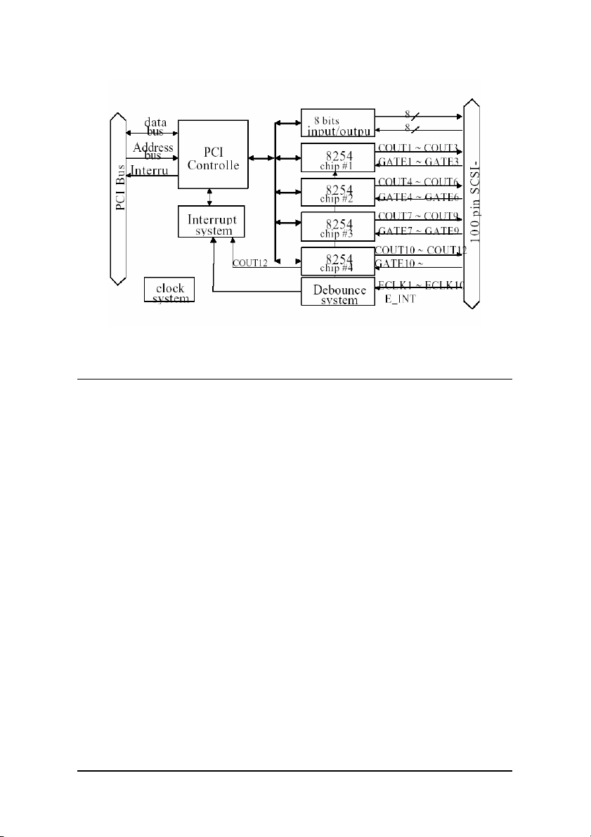
Figure 1: Functional Block diagram
1.1 Features
The cPCI/PCI-8554/R Counter / Timer and digital I/O Card provides the
following advanced features:
Four 8254 chips provide twelve 16 bits down counters
•
Multi-configurations of counters / timers:
•
Flexible setting for each independent counter, the clock
•
source could be external, internal or cascaded. The gate
signal is external controlled or internal enabled.
Provide debounce function with flexible setting to prevent
•
from bounce phenomenon when using external clocks.
8 digital output channels
•
8 digital input channels
•
Dual interrupt sources
•
3 From output of counter #12, or
3 From external source.
100-pin SCSI-II female connector.
•
PCI-Bus
•
2 • Introduction

1.2 Applications
Event counter
•
Frequency generator
•
Frequency synthesizer
•
Pulse width measurement
•
Low level pulse generator
•
Time delay
•
Industry automation
•
Watchdog timer
•
1.3 Specifications
Programmable Counter / Timer
Device:
•
Number of Counters/timers:
•
3 10 independent timers / counters
3 2 cascaded timers / counters
3 Cascaded 32-bit counters with fixed 8MHz internal
Counter mode:
•
Maximum input frequency:
•
Clock sources of independent counters:
•
3 External clock
3 Prior counter output
3 Clock #10 output
3 CK1 (Programmable)
CK1 clock sources:
•
3 8MHz internal base clock
3 Programmable counter 11 output
Gate control:
•
82C54x4
clock
default enable or external control
16-bit down counter
8 MHz
(Programmable)
Introduction •3

Digital Filter Circuits
Device:
•
De-bounce clock
•
MC14490
: (Programmable)
3 8MHz internal base clock
3 Programmable counter 11 output
Digital I/O (DIO)
No. of input channels :
•
No. of output channels :
•
Characteristics:
•
TTL compatible signal
General Specifications
Connector
•
Operating Temperature
•
: 100-pin SCSI-II female connector
8 channels
8 channels (dedicated output)
: 0°C ~ 60°C
Storage Temperature
•
Humidity
•
Power Consumption
•
Dimension
•
: 5 ~ 95%, non-condensing
: 134mm(L) X 107mm(W)
: -20°C ~ 80°C
: +5 V @ 350 mA typical
4 • Introduction

1.4 Software Supporting
ADLINK provides versatile software drivers and packages for users’
different approach to building a system. ADLINK not only provides
programming libraries such as DLL for most Windows based systems, but
also provide drivers for many other software packages such as LabVIEW®,
HP VEETM, DASYLabTM, InTouchTM, InControlTM, ISaGRAFTM, and
so on.
All software options are included in the ADLINK CD. Non-free software
drivers are protected with licensing codes. Without the software code, you
can install and run the demo version for two hours for trial/demonstration
purposes. Please contact ADLINK dealers to purchase the formal license.
1.4.1 Programming Library
For customers who are writing their own programs, we provide function
libraries for many different operating systems, including:
DOS Library:
descriptions are included in this user’s guide.
Windows 95 DLL:
are included in this user’s guide.
PCIS-DASK:
NT and Windows 2000. DLL is binary compatible across Windows 98,
Windows NT and Windows 2000. This means all applications developed
with PCIS-DASK are compatible with Windows 98, Windows NT and
Windows 2000. The developing environment can be VB, VC++, Delphi,
BC5, or any Windows programming language that allows calls to a DLL.
The user’s guide and function reference manual of PCIS-DASK are
included in the CD. Please refer to the PDF files under
\\Manual_PDF\Software\PCIS-DASK
PCIS-DASK/X:
developing environment can be Gnu C/C++ or any programming language
that allows linking to a shared library. The user's guide and function
reference manual of D2K-DASK/X are included in the CD.
(\Manual_PDF\Software\D2K-DASK-X.)
The above software drivers are shipped with the board. Please refer to
the “Software Installation Guide” for installation procedures.
Borland C/C++ and Microsoft C++, the functional
For VB, VC++, Delphi, BC5, the functional descriptions
Include device drivers and DLL for Windows 98, Windows
Include device drivers and shared library for Linux. The
Introduction •5

1.4.2 PCIS-LVIEW: LabVIEW® Driver
PCIS-LVIEW contains the VIs, which is used to interface with the NI
LabVIEW® software package. The PCIS-LVIEW supports Windows
95/98/NT/2000. The LabVIEW® drivers are shipped free with the board.
For more information about PCIS-LVIEW, please refer to the user’s guide
in the CD. (\\Manual_PDF\Software\PCIS-LVIEW)
1.4.3 PCIS-VEE: HP-VEE Driver
The PCIS-VEE includes user objects, which are used to interface with the
HP VEE software package. PCIS-VEE supports Windows 95/98/NT. The
HP-VEE drivers are shipped free with the board. For more information
about PCIS-VEE, please refer to the user’s guide in the CD.
(\\Manual_PDF\Software\PCIS-VEE)
1.4.4 DAQBenchTM: ActiveX Controls
We suggest customers who are familiar with ActiveX controls and
VB/VC++ programming use the DAQBenchTM ActiveX Control
components library for developing applications. The DAQBenchTM is
designed under Windows NT/98. For more information about DAQBench,
please refer to the user’s guide in the CD.
(\\Manual_PDF\Software\DAQBench\DAQBench Manual.PDF)
6 • Introduction

2
Getting Started
This chapter discusses how to setup the cPCI/PCI-8554R and configure
the card to meet the requirements of your application. The contents of the
package and unpacking information that you should be aware off are
outlined first.
2.1 What You Have
In addition to this User's Manual, the package should includes the
following items:
cPCI/PCI-8554/R Enhanced Multi-function Counter / Timer
•
Card
ADLINK CD
•
Software Installation Guide
•
If any of these items are missing or damaged, contact the dealer from
whom you purchased the product. Save the shipping materials and carton
in case you want to ship or store the product in the future.
2.2 Unpacking
Your cPCI/PCI-8554/R card contains electro-static sensitive components
that can be easily be damaged by static electricity.
Therefore, the card should be handled on a grounded anti-static mat. The
operator should be wearing an anti-static wristband, grounded at the same
point as the anti-static mat.
Getting Started •7
Inspect the card module carton for obvious damages. Shipping and
handling may cause damage to your module. Be sure there are no
shipping and handling damages on the modules carton before continuing.
After opening the card module carton, extract the system module and
place it only on a grounded anti-static surface with component side up.
Again, inspect the module for damages. Press down on all the socketed
IC's to make sure that they are properly seated. Do this only with the
module placed on a firm flat surface.
Note: DO NOT APPLY POWER TO THE CARD IF IT HAS BEEN
DAMAGED.
You are now ready to install your cPCI/PCI-8554/R.
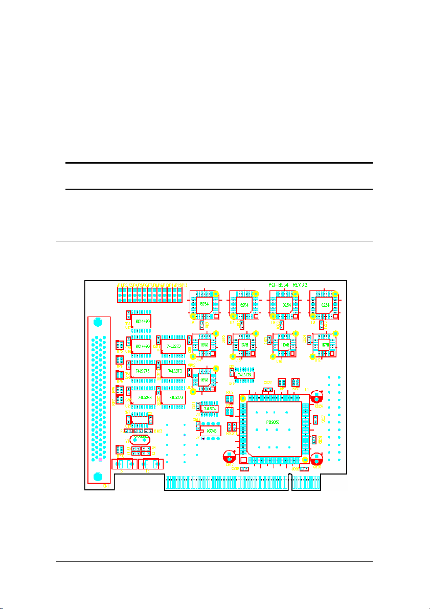
2.3 PCB Layout of cPCI/PCI-8554/R
8 • Getting Started
Figure 2: PCB Layout of PCI-8554
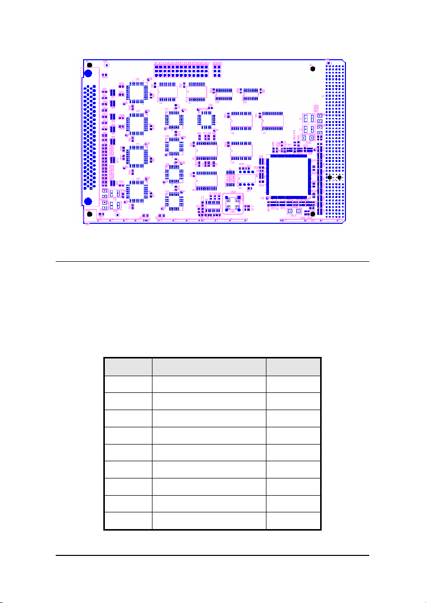
Figure 3: PCB Layout of cPCI-8554/R
2.4 Default Jumper Setting
To operate the cPCI/PCI-8554/R correctly, users need to understand the
structure of cPCI/PCI-8554/R and details of the possible configurations.
The functional block diagram of the cPCI/PCI-8554/R is shown in figure 1
of chapter 1. The following section lists the default jumper setting on the
cPCI/PCI-8554/R.
Items Default Configuration Set by
ECLK1 No Debounce function JP1
ECLK2 No Debounce function JP2
ECLK3 No Debounce function JP3
ECLK4 No Debounce function JP4
ECLK5 No Debounce function JP5
ECLK6 No Debounce function JP6
ECLK7 No Debounce function JP7
ECLK8 No Debounce function JP8
ECLK9 No Debounce function JP9
Getting Started •9

ECLK10 No Debounce function JP10
E_INT No Debounce function JP11
ECLK11 Internal 8MHz Clock JP12
ECLK12 Output of CLK11 JP13
Table 1. Default Jumper Settings on PCI-8554
Items Default Configuration Set by
GATE11 Vcc JP14
GATE12 Vcc JP15
Table 2. Extra Default Jumper Setting on cPCI-8554/R
There are 13 jumpers available on the PCI-8554, and 15 jumpers on the
cPCI-8554/R, the first 11 jumpers are used to select the debounce function.
JP12 and JP13 are used for selecting the clock source for Counter No. 11
and 12. The default setting for counter No. 11 and 12 are cascaded for
frequency division. Refer to section 2.9 for more details. JP14 and JP15
are used for selecting the gate voltages of counter No. 11 and 12 (only for
cPCI-8554/R). Users can change the cPCI/PCI-8554/R's default
configuration by setting jumpers on the card to suit the application. The
card's jumpers are preset at the factory.
Before changing the default configuration, users must fully understand the
operation of the debounce function. The setting and the basic operation
theory are not discussed in this chapter. Refer to section 2.12 for details
of the operation theory and than refer to chapter 4 for application notes.
10 • Getting Started

2.5 cPCI/PCI-8554/R Installation
2.5.1 Hardware configuration
The PCI cards (or CompactPCI cards) is equipped with the plug and play
PCI controller, it has the ability to request base addresses and interrupts
according to the PCI standard. The systems BIOS will install the system
resources based on the PCI cards’ configuration registers and system
parameters (which are set by system BIOS). Interrupt assignments and
memory usage (I/O port locations) of the PCI cards are also assigned by
system BIOS. This system resource assignment is done on a board-byboard basis. It is not suggested to assign system resources by any other
methods.
The PCI card can be inserted into any PCI slot without the need for any
system resource configuration.
2.5.1.1 Installation Procedures
1. Turn off your computer
2. Turn off all accessories (printer, modem, monitor, etc.)
connected to your computer.
3. Remove the cover from your computer.
4. Setup jumpers on the PCI or CompactPCI card.
5. Select a 32-bit PCI slot. PCI slot are shorter than ISA or
EISA slots, and are usually white or ivory in color.
6. Before handling the PCI cards, discharge any static buildup
on your body by touching the metal case of the computer.
Hold the edge and do not touch the components.
7. Position the board into the PCI slot you selected.
8. Secure the card in place at the rear panel of the system.
Getting Started •11
 Loading...