

Page 1
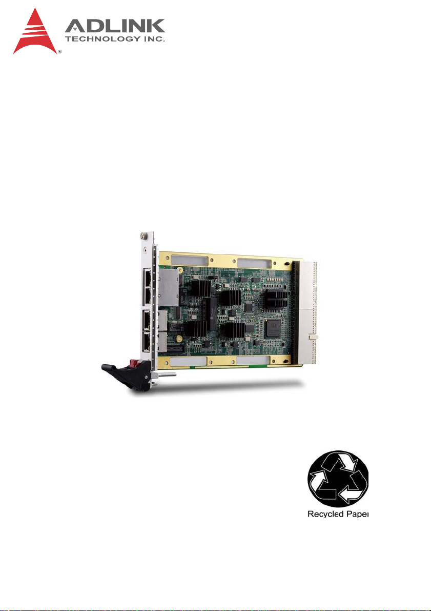
cPCI-3E10 Series
3U CompactPCI 4/2 Port
Gigabit Ethernet Card
User’s Manual
Manual Rev.: 2.00
Revision Date: November 15, 2011
Part No: 50-15073-1000
Advance Technologies; Automate the World.
Page 2

Revision History
Revision Release Date Description of Change(s)
2.00 2011/11/15 Initial release
ii Revision History
Page 3

cPCI-3E10
Preface
Copyright 2011 ADLINK Technology Inc.
This document contains proprietary infor mation protected by copyright. All rights are reserved. No part of this manual may be reproduced by any mechanical, electronic, or other means in any form
without prior written permission of the manufacturer.
Disclaimer
The information in this document is subject to change without prior
notice in order to improve reliability, design, and function and does
not represent a commitment on the part of the manufa cturer.
In no event will the manufacturer be liable for direct, indirect, special, incidental, or consequential damages arising out of the use or
inability to use the product or documentation, even if advised of
the possibility of such damages.
Environmental Responsibility
ADLINK is committed to fulfill its social responsibility to global
environmental preservation through compliance with the European Union's Restriction of Hazardous Substances (RoHS) directive and Waste Electrical and Electronic Equipment (WEEE)
directive. Environmental protection is a top priority for ADLINK.
We have enforced measures to ensure that our products, manufacturing processes, components, and raw materials have as little
impact on the environment as possible. When products are at their
end of life, our customers are encouraged to dispose of them in
accordance with the product disposal and/or recovery programs
prescribed by their nation or company.
Trademarks
Product names mentioned herein are used for identification purposes only and may be trademarks and/or registered trademarks
of their respective companies.
Preface iii
Page 4

Using this Manual
Audience and Scope
The cPCI-3E10 User’s Manual is intended for hardware
technicians and systems operators with knowledge of installing,
configuring and operating industrial grade single boar d computers.
Manual Organization
This manual is organized as follows:
Chapter 1, Introduction: Introduces the cPCI-3E10 Series, its
features, specifications and block diagrams.
Chapter 2, Board Interfaces: Describes the cPCI-3E10 board
interfaces, pin definitions, and jumper settings.
Chapter 3, Driver Installation: Provides information on how to
install the cPCI-3E10 drivers.
Important Safety Instructions: Presents safety instructions all
users must follow for the proper setup, installation and usage of
equipment and/or software.
Getting Service: Contact information for ADLINK’s worldwide
offices.
iv Preface
Page 5
cPCI-3E10
Conventions
Take note of the following conventions used throughout this
manual to make sure that users perform certain tasks and
instructions properly.
Additional information, aids, and tips that help users perform
tasks.
NOTE:
NOTE:
Information to prevent minor physical injury, component damage, data loss, and/or program corruption when trying to com-
CAUTION:
WARNING:
plete a task.
Information to prevent serious physical injury, component
damage, data loss, and/or program corruption when trying to
complete a specific task.
Preface v
Page 6

This page intentionally left blank.
vi Preface
Page 7

cPCI-3E10
Table of Contents
Revision History...................................................................... ii
Preface.................................................................................... iii
List of Figures........................................................................ ix
List of Tables.......................................................................... xi
1 Introduction ........................................................................ 1
1.1 Overview.............................................................................. 1
1.2 Features............................................................................... 1
1.3 Specifications....................................................................... 2
1.4 I/O Connectivity Table ......................................................... 3
1.5 Block Diagrams.................................................................... 3
2 Board Interfaces................................................................. 5
2.1 Board Layout ....................................................................... 5
2.2 Connectors and Jumpers..................................................... 9
3 Driver Installation............................................................. 13
3.1 cPCI-3E10 Driver............................................................... 13
Important Safety Instructions.............................................. 15
Getting Service...................................................................... 17
vii
Page 8

viii
This page intentionally left blank.
Page 9

cPCI-3E10
List of Figures
Figure 1-1: cPCI-3E10 Block Diagram...............................................3
Figure 1-2: cPCI-3E12 Block Diagram...............................................4
Figure 1-3: cPCI-3E10-SUB Block Diagram ......................................4
Figure 2-1: cPCI-3E10 Board Layout................................................. 5
Figure 2-2: cPCI-3E10 Front Panel.................................................... 5
Figure 2-3: cPCI-3E12 Board Layout................................................. 6
Figure 2-4: cPCI-3E12 Front Panel.................................................... 6
Figure 2-5: cPCI-3E10-SUB Board Layout ........................................7
Figure 2-6: cPCI-3E10-SUB Front Panel ........................................... 7
Figure 2-7: cPCI-R3E10 RTM Board Layout..................... ... ... ....... ... . 8
Figure 2-8: cPCI-R3E10 RTM Front Panel .................................... ... . 8
List of Figures ix
Page 10

This page intentionally left blank.
xList of Figures
Page 11

cPCI-3E10
List of Tables
Table 1-1: cPCI-3E10 Specifications........... .... ... ... ... ... .... ... ... ... .... ... . 2
Table 2-1: RJ-45 Pin Definitions....................................................... 9
Table 2-2: LAN Status LED Definitions.............................................9
Table 2-3: DB-9 LAN1/2 Connector Pin Definition.......................... 10
Table 2-4: CompactPCI J1 Connector Pin Definition...................... 11
Table 2-5: CompactPCI J2 Connector Pin Definition...................... 12
List of Tables xi
Page 12

This page intentionally left blank.
xii List of Tables
Page 13

1 Introduction
1.1 Overview
The cPCI-3E10 Series is 3U CompactPCI Gigabit Ethernet peripheral card equipped with Intel® 82574L PCIe Gigabit Ethernet controllers. The cPCI-3E10 provides four GbE ports on the front panel
(RJ-45) with two switchable to the rear transition module, the
cPCI-3E12 provides two GbE ports on the fr ont p anel (RJ-45) , and
the cPCI-3E10-SUB provides two Fast Ethernet ports on the front
panel (DB-9).
An optional Rear Transition Module (cPCI-R3E10) is available to
provide rear access to the GbE ports switched from the
cPCI-3E10 front panel.
1.2 Features
X Standard 3U 4HP CompactPCI form factor
X Up to 64-bit/66MHz CompactPCI Interface
X Up to four Intel® 82574L Ethernet controllers with fully-inte-
grated GbE MAC & PHY
X Four or two 10/100/1000BASE-T Gigabit Ethernet ports via
RJ-45 connectors
X Two LAN ports switchable to rear (cPCI-3E10 only)
X Two Fast Ethernet ports via D-sub 9-pin connectors
(cPCI-3E10-SUB only) for harsh environment applications
X PICMG® 2.0 R3.0 compliant
cPCI-3E10
This product must be protected from static discharge and physical shock. Never remove any of the components except at a
CAUTION:
Introduction 1
static-free workstation. Use the anti-static bag shipped with the
product when putting the board on a surface. Wear an
anti-static wrist strap properly grounded on one of the system's
ESD ground jacks when installing or servicing system components.
Page 14

1.3 Specifications
PCI Bus
Architecture
Ethernet
Controller
Ethernet Ports • cPCI-3E10/3E12: Four or two RJ-45 connectors
Ethernet LEDs • Each RJ-45 port and DB-9 port has two "Link/Active" LEDs
Boot ROM • LAN Boot ROM: 128KB onboard
OS Support • Microsoft Windows Server 2003 and 2008
Network
Management
Environment • Operating Temperature: 0°C to 60°C
Dimensions • 149 mm x 74 mm x 10 mm (L x W x H)
Note: Specifications are subject to change without prior notice.
• Bus Type: PCI
• Bus Width: 32- or 64-bit
• Bus Speed: 33/66 MHz
• PCI Voltage: 3.3V or 5V universal
• Intel 82574L Gigabit Ethernet Controller running at PCIe 1.1
(2.5 GHz) x1
• 4x GbE ports on cPCI-3E10, 2x GbE ports on cPCI-3E12
• Data rates supported (per port): 10/100/1000 Mbps
• IEEE Standard/Network Topology: 10BASE-T, 100BASE-TX,
1000BASE-T
• IEEE 802.3ab compliant
• cPCI-3E10-SUB: Two DB-9 10/100 Mbps Fast LAN
connectors
• cPCI-R3E10: Two RJ-45 connectors
• Wiring: Cat-5, 4-pair, Maximum 100 meters cable distance
• Microsoft Windows XP, Vista, 7
• Red Hat Enterprise Linux 5.0 and above
(Contact ADLINK for other OS availability)
• ACPI Power Management
• Supports Intel Preboot Execution Environment (PXE 2.0) for
remote boot
• Storage Temperature: -40°C to 70°C
• Humidity: 95% @70°C, non-condensing
Table 1-1: cPCI-3E10 Specifications
2Introduction
Page 15

cPCI-3E10
1.4 I/O Connectivity Table
Function Model Faceplate
cPCI-3E10 Y x4
GbE (RJ-45)
Fast Ethernet (DB-9) cPCI-3E10-SUB Y x2
cPCI-3E12 Y x2
cPCI-R3E10 Y x2
1.5 Block Diagrams
cPCI-3E10 Block Diagram
The cPCI-3E10 is based on four Intel® 82574L PCI express Gigabit Ethernet controllers. The Intel® 82574L is a highly integrated
chip including Ethernet MAC and PHY. Please refer to the Intel®
82574L datasheet for more information.
LAN1
LAN2
LAN3
LAN4
GbE
GbE
GbE
GbE
Switch
Transformer
Transformer
Switch
Transformer
Intel
82574L-A
Intel
82574L-B
Intel
82574L-C
Intel
82574L-D
PCIE x1
PCIE x1
PCIE x1
PCIE x1
PEX8608
PCIE x4
PI7C9X130
J2
J1
Figure 1-1: cPCI-3E10 Block Diagram
Introduction 3
Page 16

cPCI-3E12 Block Diagram
LAN1
LAN2
GbE
GbE
Transformer
Intel
82574L-C
Intel
82574L-D
Figure 1-2: cPCI-3E12 Block Diagram
cPCI-3E10-SUB Block Diagram
LAN1
LAN2
10/100
10/100
Transformer
B2B
Conn
.
Figure 1-3: cPCI-3E10-SUB Block Diagram
Intel
82574L-C
Intel
82574L-D
PCIE x1
PCIE x1
PCIE x1
PCIE x1
PCIE x4
PCIE x4
PI7C9X130PEX8608
PI7C9X130PEX8608
J1
J1
4Introduction
Page 17

2 Board Interfaces
This chapter illustrates the board layout, connector pin
assignments, and jumper settings of the cPCI-3E10 Series.
2.1 Board Layout
cPCI-3E10 Board Layout
cPCI-3E10
LAN1/2
LAN3
LAN4
U12
U10
JP1
U6
U14
U3
U16
J2
J1
JP1 LAN routing jumper U3 PCIe-to-PCI Bridge PI7C9X130
J1/2 CompactPCI connectors U6 PCIe Switch PEX8608
LAN1/2 GbE ports (RJ-45 w/
transformer)
U10/12/
14/16
Intel 82574L GbE controllers
LAN3/4 GbE ports (RJ-45)
Figure 2-1: cPCI-3E10 Board Layout
Figure 2-2: cPCI-3E10 Front Panel
Board Interfaces 5
Page 18

cPCI-3E12 Board Layout
LAN1
LAN2
U3 PCIe-to-PCI Bridge
PI7C9X130
U14/16 Intel 82574L GbE
controllers
J1 CompactPCI connector
Figure 2-3: cPCI-3E12 Board Layout
U14
U16
U3
U6
J1
U6 PCIe Switch PEX8608
LAN1/2 GbE ports (RJ-45)
Figure 2-4: cPCI-3E12 Front Panel
6 Board Interfaces
Page 19

cPCI-3E10-SUB Board Layout
cPCI-3E10
LAN1
LAN2
U3 PCIeto PCI Bridge
PI7C9X130
U14/16 Intel 82574L GbE
controllers
J1 CompactPCI connector
Figure 2-5: cPCI-3E10-SUB Board Layout
U14
U16
U6
U3
J1
U6 PCIe Switch PEX8608
LAN1/2 Fast Ethernet (DB-9)
Figure 2-6: cPCI-3E10-SUB Front Panel
Board Interfaces 7
Page 20

cPCI-R3E10 RTM Board Layout
J2
LAN1
LAN2
J2 CompactPCI connector LAN1/2 GbE ports (RJ-45)
Figure 2-7: cPCI-R3E10 RTM Board Layout
Figure 2-8: cPCI-R3E10 RTM Front Panel
8 Board Interfaces
Page 21

cPCI-3E10
2.2 Connectors and Jumpers
RJ-45 Ethernet Connectors
On the cPCI-3E10, LAN1/2 correspond to "A/B", and LAN3/4 correspond to "C/D". On the cPCI-3E12, LAN1/2 correspond to "C/D".
On the cPCI-R3E10 RTM, LAN1/2 correspond to "A/B".
Pin #
1 TX+ TRANS_ A/B/C/D_MDIP0
2 TX- TRANS_ A/B/C/D_MDIN0
3 RX+ TRANS_ A/B/C/D_MDIP1
4 — TRANS_ A/B/C/D_MDIP2
5 — TRANS_ A/B/C/D_MDIN2
6 RX- TRANS_ A/B/C/D_MDIN1
7 — TRANS_ A/B/C/D_MDIP3
8 — TRANS_ A/B/C/D_MDIN3
Network link is not established
or system powered off
10 Mbps
100 Mbps
1000 Mbps
10BASE-T/
100BASE-TX
Table 2-1: RJ-45 Pin Definitions
Speed
Status
Link OFF ON
Active OFF Blinking
Link Green ON
Active Green Blinking
Link Orange ON
Active Orange Blinking
Activity
18
Speed LED
(Green/Orange)
OFF OFF
1000BASE-T
Activity LED
(Yellow)
Ta bl e 2-2: LAN Status LED Definitions
Board Interfaces 9
Page 22

LAN Routing Jumper (JP1)
The cPCI-3E10 is equipped with a jumper JP1 to transfer LAN1/2
(82574L-A and 82574L-B) to J2 (RTM). See “cPCI-3E10 Board
Layout” on page 5 for the location of JP1.
Short pins 1 and 2 on JP1 to route LAN1/2 to the front RJ-45 connectors (default). To route LAN1/2 to J2, remove the shunt shorting pins 1 and 2 (it can be placed on either pin for storage).
LAN1/2 DB-9 Connector on cPCI-3E10-SUB
On the cPCI-3E10-SUB, LAN1/2 correspond to "C/D".
Pin # Signal Function
1 TRANS_C/D_MDIP0 TX+
2 GND ground
3 GND ground
4 GND ground
5 TRANS_C/D _MDIP1 RX+
6 TRANS_C/D _MDIN0 TX7 GND ground
8 GND ground
9 TRANS_C/D _MDIN1 RX-
Ta ble 2-3: DB-9 LAN1/2 Connector Pin Definition
6
1
5
10 Board Interfaces
Page 23

cPCI-3E10
CompactPCI J1 Connector
Pin Z A B C D E F
25 GND P5V CPCI_REQ64-L CPCI_ENUM-L P3V3 P5V GND
24 GND CPCI_AD1 P5V NC CPCI_AD0
23 GND P3V3 CPCI_AD4 CPCI_AD3 P5V CPCI_AD2 GND
22 GND CPCI_AD7 GND P3V3 CPCI_AD6 CPCI_AD5 GND
21 GND P3V3 CPCI_AD9 CPCI_AD8 PCI_M66EN CPCI_CBE-L0 GND
20 GND CPCI_AD12 GND NC CPCI_AD1 1 CPCI_AD10 GND
19 GND P3V3 CPCI_AD15 CPCI_AD14 GND CPCI_AD13 GND
18 GND CPCI_SERR-L GND P3V3 CPCI_PAR CPCI_CBE-L1 GND
17 GND P3V3 IPMB_CLK IPMB_DAT GND CPCI_PERR-L GND
16 GND CPCI_DEVSEL-L GND NC CPCI_STOP-L CPCI_LOCK-L GND
15 GND P3V3 CPCI_FRAME-L CPCI_IRDY-L GND CPCI_TRDY-L GND
12-14 Key
11 GND CPCI_AD18 CPCI_AD17 CPCI_AD16 GND CPCI_CBE-L2 GND
10 GND CPCI_AD21 GND P3V3 CPCI_AD20 CPCI_AD19 GND
9 GND CPCI_CBE-L3 CPCI_IDSEL CPCI_AD23 GND CPCI_AD22 GND
8 GND CPCI_AD26 GND NC CPCI_AD25 CPCI_AD24 GND
7 GND CPCI_AD30 CPCI_AD29 CPCI_AD28 GND CPCI_AD27 GND
6 GND CPCI_REQ-L0 GND P3V3 CPCI_CLK CPCI_AD31 GND
5 GND NC NC CPCI_RST-L GND CPCI_GNT-L0 GND
4 GND NC NC NC NC NC GND
3 GND CPCI_INTA-L CPCI_INTB-L CPCI_INTC-L P5V CPCI_INTD-L GND
2 GND CPCI_TCK P5V CPCI_TMS NC CPCI_TDI GND
1 GND P5V NC CPCI_TRST-L NC P5V GND
Table 2-4: CompactPCI J1 Connector Pin Definition
CPCI_ACK64-L
GND
Board Interfaces 11
Page 24

CompactPCI J2 Connector
Pin Z A B C D E F
22 GND N28342162 N28355309 N28355465 N28355622 N28346930 GND
21 GND NC GND NC NC NC GND
20 GND NC GND NC GND NC GND
19 GND GND GND NC NC NC GND
18 GND NC NC NC GND NC GND
17 GND NC GND NC NC NC GND
16 GND NC NC NC GND NC GND
15 GND NC GND NC NC NC GND
14 GND NC NC NC GND NC GND
13 GND P1V8_LANB GND NC NC P1V8_LANA GND
12 GND
11 GND NC N28043456 NC P3V3 P5V GND
10 GND NC NC NC N28028706 NC GND
9GND GND GND
8GND
7 GND GND GND GND
6GND
5 GND GND GND GND
4GND
3 GND GND GND GND
2GND
1 GND GND GND GND
LANB_LED
_100-L
TRANS_J2_B
_MDIP2
TRANS_J2_B
_MDIP3
TRANS_J2_B
_MDIP0
TRANS_J2_B
_MDIP1
Table 2-5: CompactPCI J2 Connector Pin Definition
LANB_LED
_1000-L
TRANS_J2_B
_MDIN2
TRANS_J2_B
_MDIN3
TRANS_J2_B
_MDIN0
TRANS_J2_B
_MDIN1
LANB_LED
_ACT-L
LANA_LED
_100-L
GND GND GND GND
GND GND GND GND
GND GND GND GND
GND GND GND GND
GND
LANA_LED
_1000-L
TRANS_J2_A
_MDIP2
TRANS_J2_A
_MDIP3
TRANS_J2_A
_MDIP0
TRANS_J2_A
_MDIP1
LANA_LED
_ACT-L
NC GND
TRANS_J2_A
_MDIN2
TRANS_J2_A
_MDIN3
TRANS_J2_A
_MDIN0
TRANS_J2_A
_MDIN1
GND
GND
GND
GND
GND
12 Board Interfaces
Page 25

3 Driver Installation
The cPCI-3E10 drivers are available from the ADLINK All-In-One
DVD at X:\cPCI\cPCI-3E10\, or from the ADLINK website
(http://www.adlinktech.com). ADLINK provides validated drivers for Windows XP and Windows Server 2003/2008. We recommend using these drivers to ensure compatibility. Driver
installation is not required for Windows V ista/7 and Red Hat Enterprise Linux.
The validated Windows driver installation files are as follows:
cPCI-3E10
Windows XP,
Server 2003
Windows Server
2008
Intel_Network_Adapter_WinXP2K332_x14.5.exe
Intel_Network_Adapter_Win2K832.exe
3.1 cPCI-3E10 Driver
The following describes the cPCI-3E10 driver installation procedure.
1. Install the Windows operating system before installing any
driver. Most standard I/O device drivers are installed during
Windows installation.
2. Select the correct file for your operating system and run the
program to install the driver.
3. Follow the on screen instructions and reboot the system if
requested to do so.
Driver Installation 13
Page 26

This page intentionally left blank.
14 Driver Installation
Page 27

cPCI-3E10
Important Safety Instructions
For user safety, please read and follow all instructions,
WARNINGS, CAUTIONS, and NOTES marked in this manual
and on the associated equipment before handling/operating the
equipment.
X Read these safety instructions carefully.
X Keep this user’s manual for future reference.
X Read the specifications section of this manual for detailed
information on the operating environment of this equipment.
X When installing/mounting or uninstalling/removing
equipment:
Z Turn off power and u nplug any power cords/cables.
X To avoid electrical shock and/or damage to equipment:
Z Keep equipment away from water or liquid sources;
Z Keep equipment away from high heat or high humidity;
Z Keep equipment properly ventilated (do not block or
cover ventilation openings);
Z Make sure to use recommended voltage and powe r
source settings;
Z Always install and operate equipment near an easily
accessible electrical socket-outlet;
Z Secure the power cord (do not place any obje ct on /ove r
the power cord);
Z Only install/attach and operate equipment on stable
surfaces and/or recommended mountings; and,
Z If the equipment will not be used for long periods of time,
turn off and unplug the equipment from its power source.
Important Safety Instructions 15
Page 28

X Never attempt to fix the equipment. Equipmen t sho u ld on ly
be serviced by qualified personnel.
A Lithium-type battery may be provided for uninterrupted, backup
or emergency power.
Risk of explosion if battery is replaced with one of an incorrect
WARNING:
type. Dispose of used batteries appropriately.
X Equipment must be serviced by authorized technicians
when:
Z The power cord or plug is damaged;
Z Liquid has penetrated the equipment;
Z It has been exposed to high humidity/moisture;
Z It is not functioning or does not function according to the
user’s manual;
Z It has been dropped and/or damaged; and/or,
Z It has an obvious sign of breakage.
16 Important Safety Instructions
Page 29

cPCI-3E10
Getting Service
Contact us should you require any service or assistance.
ADLINK Technology, Inc.
Address: 9F, No.166 Jian Yi Road, Zhonghe District
New Taipei City 235, Taiwan
ᄅקؑխࡉ৬ԫሁ 166 ᇆ 9 ᑔ
Tel: +886-2-8226-5877
Fax: +886-2-8226-5717
Email: service@adlinktech.com
Ampro ADLINK Technology, Inc.
Address: 5215 Hellyer Avenue, #110, San Jose, CA 95138, USA
Tel: +1-408-360-0200
Toll Free: +1-800-966-5200 (USA only)
Fax: +1-408-360-0222
Email: info@adlinktech.com
ADLINK Technology (China) Co., Ltd.
Address: Ϟ⍋Ꮦ⌺ϰᮄᓴ∳催⾥ᡔು㢇䏃 300 ো(201203)
300 Fang Chun Rd., Zhangjiang Hi-Tech Park,
Tel: +86-21-5132-8988
Fax: +86-21-5132-3588
Email: market@adlinktech.com
ADLINK Technology Beijing
Address: ࣫ҀᏖ⍋⎔Ϟഄϰ䏃 1 োⲜ߯ࡼ E ᑻ 801 ᅸ(100085)
Tel: +86-10-5885-8666
Fax: +86-10-5885-8625
Email: market@adlinktech.com
ADLINK Technology Shenzhen
Address: ⏅ഇᏖቅ⾥ᡔು催ᮄϗ䘧᭄ᄫᡔᴃು
Tel: +86-755-2643-4858
Fax: +86-755-2664-6353
Email: market@adlinktech.com
Pudong New Area, Shanghai, 201203 China
Rm. 801, Power Creative E, No. 1, B/D
Shang Di East Rd., Beijing, 100085 China
A1 2 ὐ C (518057)
2F, C Block, Bldg. A1, Cyber-Tech Zone, Gao Xin Ave. Sec. 7,
High-Tech Industrial Park S., Shenzhen, 518054 China
Getting Service 17
Page 30

ADLINK Technology (Europe) GmbH
Address: Nord Carree 3, 40477 Duesseldorf, Germany
Tel: +49-211-495-5552
Fax: +49-211-495-5557
Email: emea@adlinktech.com
ADLINK Technology, Inc. (French Liaison Office)
Address: 15 rue Emile Baudot, 91300 Massy CEDEX, France
Tel: +33 (0) 1 60 12 35 66
Fax: +33 (0) 1 60 12 35 66
Email: france@adlinktech.com
ADLINK Technology Japan Corporation
Address: ͱ101-0045 ᵅҀ䛑ҷ⬄⼲⬄䤯ފ⬎ 3-7-4
⼲⬄ 374 ɛɳ 4F
KANDA374 Bldg. 4F, 3-7-4 Kanda Kajicho,
Chiyoda-ku, Tokyo 101-0045, Japan
Tel: +81-3-4455-3722
Fax: +81-3-5209-6013
Email: japan@adlinktech.com
ADLINK Technology, Inc. (Korean Liaison Office)
Address: 昢殾柢 昢爎割 昢爎壟 1675-12 微汾瘶捒娯 8猻
8F Mointer B/D,1675-12, Seocho-Dong, Seocho-Gu,
Seoul 137-070, Korea
Tel: +82-2-2057-0565
Fax: +82-2-2057-0563
Email: korea@adlinktech.com
ADLINK Technology Singapore Pte. Ltd.
Address: 84 Genting Lane #07-02A, Cityneon Design Centre,
Singapore 349584
Tel: +65-6844-2261
Fax: +65-6844-2263
Email: singapore@adlinktech.com
ADLINK Technology Singapore Pte. Ltd. (Indian Liaison Office)
Address: No. 1357, "Anupama", Sri Aurobindo Marg, 9th Cross,
JP Nagar Phase I, Bangalore - 560078, India
Tel: +91-80-65605817
Fax: +91-80-22443548
Email: india@adlinktech.com
18 Getting Service
 Loading...