

Page 1

cPCI-3534 cPCI -3538
4/8 Ports Serial
Communication Modules
Page 2

Page 3

@Copyright 1996~99 ADLink Technology Inc.
All Rights Reserved.
Manual Rev 1.00: October 12, 1999
The information in this document is subject to change without prior notice in order
to improve reliability, design and function and does not represent a commitment on
the part of the manufacturer.
In no event will the manufacturer be liable for direct, indirect, special, incidental, or
consequential damages arising out of the use or inability to use the product or
documentation, even if advised of the possibility of such damages.
This document contains proprietary information protected by copyright. All rights
are reserved. No part of this manual may be reproduced by any mechanical,
electronic, or other means in any form without prior written permission of the
manufacturer.
Trademarks
cPCI-3534 and cPCI -3538 are registered trademarks of ADLink Technology Inc.,
MS-DOS, Windows 95, Windows NT are registered trademark of Microsoft
Corporation. Intel is a registered trademark of Intel Corporation. Other product
names mentioned herein are used for identification purposes only and may be
trademarks and/or registered trademarks of their respective companies.
Page 4
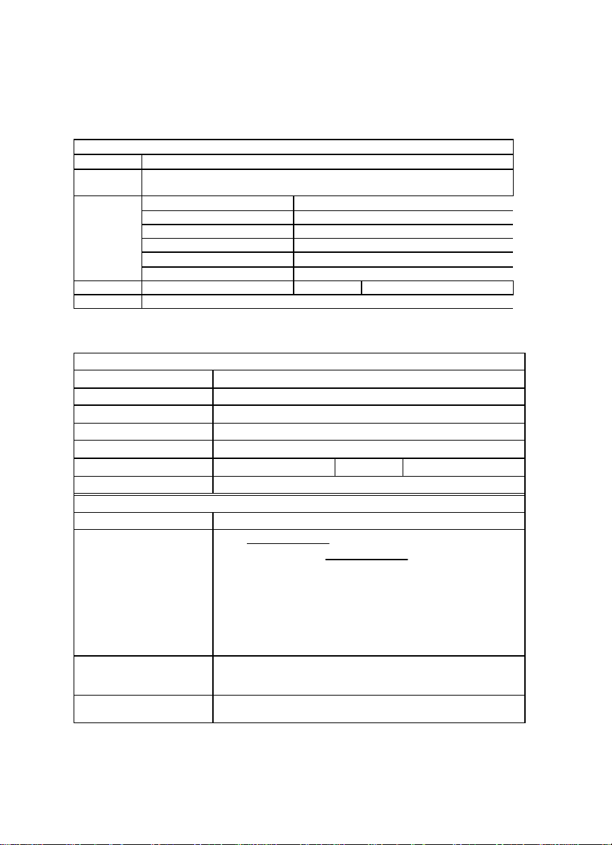
Getting service from ADLink
♦ Customer Satisfaction is always the most important thing for ADLink Tech Inc.
If you need any help or service, please contact us and get it.
Web Site http://www.adlink.com.tw
Sales and
Service
Technical NuDAQ nudaq@adlink.com.tw
Support NuDAM nudam@adlink.com.tw
TEL +886-2-82265877 FAX +886-2-82265717
Address 9F, No. 166, Jian Yi Road, Chungho City, Taipei 235, Taiwan, R.O.C.
service@adlink.com.tw
NuIPC nuipc@adlink.com.tw
NuPRO nupro@adlink.com.tw
Software sw@adlink.com.tw
AMB amb@adlink.com.tw
♦ Please inform us of your detailed information for a prompt, satisfactory
and constant service.
Company/Organization
Contact Person
E -mail Address
Address
Country
TEL
Web Sit
Product Model
Environment to Use OS
Challenge Description
Suggestions for ADLink
ADLink Technology Inc.
Detailed Company Information
FAX
Questions
Computer Brand
M/B : CPU :
Chipset : Bios :
Video Card :
Network Interface Card :
Other :
Page 5

ADLink cPCI Multiport Card Comparison Chart
Port D: Isolated RS422 or
3534 3538
Serial port 4~8 8~16
CPU
Serial communication
controller
MAX System throughput 115.2K*4 115.2K*8
Hardware compatibility cPCI bus cPCI bus
Software compatibility
External connector
Rear IO Connector R3534 R3538
Surge protection Y Y
Isolation protection
(500VDC)
(RS232,RS422, RS485)
Dimension
- -
16C554 16C554
DOS Windows
(3.1/95/98/NT) LINUX
SCO Open Server
Four DB25 male cable
connector
RS 485
160mm (length)
100mm (width)
DOS Windows
(3.1/95/98/NT) LINUX
SCO Open Server
Eight DB25 male cable
connector
Y (C888XB) option
160mm (length)
100mm (width)
Page 6

Page 7

CONTENTS
CONTENTS ................................................................I
CHAPTER 1 INTRODUCTION………………………….1
1.1 ABOUT THE SERIAL COMMUNICATION MODULES………..………….1
1.2 OVERVIEW OF CPCI-3534 ....................................................... 2
1.2.1 What is cPCI -3534?…………………..……….……………………..2
1.2.2 Feature of cPCI -3534..........................................................................2
1.2.3 Specification of cPCI -3534................................................................2
1.2.4 Connector Pin Assignment of cPCI-3534......................................3
1.3 OVERVIEW OF CPCI-3538 ....................................................... 6
1.3.1 What is cPCI -3538?.............................................................................6
1.3.2 Feature of cPCI -3538..........................................................................6
1.3.3 Specification of cPCI -3538................................................................7
1.3.4 Connector Pin Assignment of cPCI-3538......................................8
CHAPTER 2 INSTALLATION ................................11
2.1 WHAT YOU HAVE................................................................... 11
2.2 UNPACKING..........................................................................12
2.3 INSTALLATION PROCEDURE.....................................................12
2.4 HARDWARE CONFIGURATION...................................................13
2.5 SOFTWARE I NSTALLATION.......................................................13
2.5.1 Windows NT Installation.................................................................13
2.5.2 Windows 95/98 Installation............................................................14
PRODUCT WARRANTY/SER VICE..........................17
Contents • i
Page 8

Page 9

1
Introduction
1.1 About the Serial Communication Modules
The serial communication modules are intelligent serial input/output
multi-port controller cards, which go with the new generation of PC
platform CompactPCI. The modules can reduce the frequency for serial
communication controller to interrupt main CPU on the mainboard to
improve the whole system performance.
Traditionally, the serial communication controller will interrupt the MPU
character by character. This action will waste MPU processing time and
drop the system computing power. If the MPU is processing some
non-interrupted task, then the serial controller will overrun and data lost.
The serial communication interface series can support buffer capability or
local processor and dual port RAM in each port’s transmit and receive
channel simultaneously. This capability will reduce the frequency of
interrupt and increase the non-interrupt task’s interval.
The serial communication interface series use ASIC PCI controller to
interface the module to cPCI bus. The ASIC fully implement the PCI local
bus specification Rev. 2.1. All related bus configurations, such as base
memory address and interrupt assignment, are automatically controlled
by BIOS software. It does not need any user interaction and pre-study for
the configurations. This removes the burden of searching for a
conflict-free configuration.
Introduction • 1
Page 10

1.2 Overview of cPCI-3534
1.2.1 What is cPCI-3534?
The cPCI -3534 is an enhanced four ports serial communication module
used for cPCI platform. It includes a PGA to support the serial
communication controller and a 37-pin connector to connect external I/O
port from the front panel or using the rear IO.
The expansion cable has four standard DB25 connectors and one DB37
connector to connect with cPCI -3534 interface card.
The R-3534 transition board can support rear IO connection by using one
DB37 connector.
1.2.2 Feature of cPCI-3534
§ 32-bit CompactPCI form factor
§ PCI Rev.2.1 Plug and Play
§ IRQ and IO address automatically assigned by PCI plug-n-play
§ 4 communication ports intelligent buf fer
§ One isolated industry communication port
§ High Speed Communication (max. 115200 bps)
§ Suitable for modems, data display, data collection,
telecommunication
§ Supports up to 2 cards/8 ports per system
§ Supports DOS, Windows 3.1, Windows 95/98, and Windows NT
operation system
1.2.3 Specification of cPCI-3534
§ Compliant with PCI Spec.2.1
§ Serial communication controller:
16C550A compatible
1.8432 ~ 7.3728 MHz
§ System IO mapping:
Assigned by PCI BIOS
Shared IRQ
§ Flow control
Xon/Xoff control
RTS/CTS control
2 • Introduction
Page 11

§ Port Capability:
3 independent RS-232C compatible ports
1 isolated RS-422/485 port (DIP switch select)
Max. port per system: 8 (2 card)
§ Isolation voltage: 2500VDC
§ Baud rate: Each port can be configured to 50~115,200 bps
§ Operation System Compat ibility: DOS, Windows 3.1, and Windows
95/98/NT
§ Connector: DB37 female connector
§ Cable: External cable with 4 standard DB25 male connector
§ Operating temperature: 0 ~ 55 °C
§ Storage temperature: -20 ~ 65 °C
§ Humidity: 10% ~ 95%, non-condensing
§ Dimension: 160 x 100 mm
§ Power consumption: +5V @ 1400mA typical
2
(6.3 x 3.9 in.2) 3U
1.2.4 Connector Pin Assignment of cPCI-3534
DB37 female connector pin assignment for cPCI -3534.
DB37 Pin No. Signal Name DB37 Pin No. Signal Name
1 RXD1(IN) 20 TXD1(OUT)
2 CTS1(IN) 21 RTS1(OUT)
3 DSR1(IN) 22 DTR1(OUT)
4 DCD1(IN) 23 RI1(IN)
5 GND 24 RXD2(IN)
6 TXD2(OUT) 25 CTS2(IN)
7 RTS2(OUT) 26 DSR2(IN)
8 DTR2(OUT) 27 DCD2(IN)
9 GND 28 RI2(IN)
10 GND 29 RI3(IN)
11 GND 30 DCD3(IN)
12 DTR3(OUT) 31 DSR3(IN)
13 RTS3(OUT) 32 CTS3(IN)
14 TXD3(OUT) 33 RXD3(IN)
15 GND4 34 -16 -- 35 422TXD4-(I/O)
17 422RXD4-(IN) 36 485TRXD4+(I/O)
18 485TRXD4-(I/O) 37 422TXD4+(OUT)
19 422RXD4+(IN) -- --
Introduction • 3
Page 12

DB25 male connector pin assignment in cPCI-3534 module for RS-232
interface (port A, B and C).
DB25 Pin No. Signal Name
2 TXD(OUT)
3 RXD(IN)
4 RTS(OUT)
5 CTS(IN)
6 DSR(IN)
7 GND
8 DCD(IN)
20 DTR(OUT)
DB25 male connector pin assignment in cPCI-3534 module for
RS-422/485 interface (port D).
DB25 Pin No. Signal Name
2 422TXD+(OUT)
3 422RXD+(IN)
4 485TRXD+(I/O)
5 485TRXD-(I/O)
6 422RXD-(IN)
7 GND
20 422TXD-(OUT)
4 • Introduction
Page 13

J2 connector pin assignment in cPCI-3534 module for RS-232/422/485
interface.
22 GND GA4 GA3 GA2 GA1 GA0 GND
21 GND GND
20 GND GND
19 GND FG N+ N- SG GND
18 GND GND
17 GND GND
16 GND TXD+ TXD- SG GND
15 GND FG RXD+ RXD- GND
14 GND GND
13 GND GND
12 GND DSRŽ SGŽ DCDŽ DTRŽ GND
11 GND FGŽ TXŽ RXŽ RTSŽ CTSŽ GND
10 GND GND
9 GND GND
8 GND DSR• SG• DCD• DTR• GND
7 GND FG• TX• RX• RTS• CTS• GND
6 GND GND
5 GND GND
4 GND DSRΠSGΠDCDΠDTRΠGND
3 GND FGΠTXΠRXΠRTSΠCTSΠGND
2 GND GND
1 GND GND
Pin Z A B C D E F
ŒPort A •Port B ŽPort C
RS -232
FG: Frame Ground TX: Transmit Data
RX: Receive Data
RTS: Request to Send CTS: Clear to Send
DSR: Data Set Ready
SG: Signal Ground DCD: Data Carrier Detect
DTR: Data Terminal Ready
RS -422
TXD+: Transmit Data Positive
TXD-: Transmit Data Negative
RXD+: Receive Data Positive
RXD-: Receive Data Negative
P2
/
J2
C
O
N
N
E
C
T
O
R
Introduction • 5
Page 14

RS -485
N+: Data Signal Positive
N-: Data Signal Negative
R-3534 Rear IO Daughter Board
The R-3534 rear I/O daughter board provides a rear I/O connection
transition, the connector and cable used in the rear is the same as the
front.
DIP Switch and Jumper Setting
SW1 ON OFF
SW1-1 Card1 Card2
SW1-4 RS-422 RS-485
The JP1 is for the RS422 terminator and the JP2 is for the RS-485
terminator. The terminator is ON while the jumper is ON
1.3 Overview of cPCI-3538
1.3.1 What is cPCI-3538?
The cPCI-3538 is an enhanced eight ports serial communication card
used for cPCI platform. It includes a PGA, which supports the serial
communication controller, and a 62-pin connector which connects
external I/O port on the front panel or the rear IO.
The expansion cable has eight standard DB25 connectors and one DB62
connector to connect to cPCI-3538 interface card. User may also use
one DB62 to DB62 cable to connect between one cPCI-3538 and
C588XB for providing 8 channel isolated RS-232/422/485 interface.
The R-3538 transition board can support rear IO connection by using one
DB62 connector.
1.3.2 Feature of cPCI-3538
§ 32-bit CompactPCI form factor
§ PCI Rev.2.1 Plug and Play
§ IRQ and IO address automatically assigned by PCI plug-and-play
§ 8 communication ports intelligent buffer
§ High Speed Communication (max. 115200 bps)
§ Suitable for modems, data display, data collection,
6 • Introduction
Page 15

telecommunication
§ Supports up to 2 cards/8 ports per system
§ Supports DOS, Windows 3.1, Windows 95/98, and Window NT
operation system
§ Optional isolated RS-232/422/485 interface for each port
independently by C888XB
1.3.3 Specification of cPCI-3538
§ Compliant with PCI Spec.2.1
§ Serial communication controller:
§ 16C550A compatible
§ 1.8432 ~ 7.3728 MHz
§ System IO mapping:
§ Assigned by PCI BIOS
§ Shared IRQ
§ Flow control
§ Xon/Xoff control
§ RTS/CTS control
§ Port Capability:
§ 8 independent RS-232C compatible ports
§ Optional external C588XB box for extending to 8 isolated
RS-232/422/485 port
§ Max. port per system: 16 (2 card)
§ Baud rate: Each port can be configured to 50~115,200 bps
§ Operation System Compatibility: DOS, Windows 3.1, and Windows
95/98/NT
§ Connector: DB62 female connector
§ Cable: External cable with 8 standard DB25 male connector
§ Operating temperature: 0 ~ 55 °C
§ Storage temperature: -20 ~ 65 °C
§ Humidity: 10% ~ 95%, non-condensing
§ Dimension: 160 x 100 mm
§ Power consumption: +5V @ 1400mA typical
2
(6.3 x 3.9 in.2) 3U
Introduction • 7
Page 16

1.3.4 Connector Pin Assignment of cPCI-3538
DB62 female connector pin assignment for cPCI -3538.
DB62 Pin
No.
1 TXD1(OUT) 22 TXD2(OUT) 43 GND
2 RXD1(IN) 23 RXD2(IN) 44 GND
3 RTS1(OUT) 24 RTS2(OUT) 45 GND
4 CTS1(IN) 25 CTS2(IN) 46 TXD4(OUT)
5 DSR1(IN) 26 DSR2(IN) 47 RXD4(IN)
6 DTR1(OUT)
7 DCD1(IN) 28 DCD2(IN) 49 CTS4(IN)
8 TXD3(OUT) 29 TXD7(OUT) 50 DSR4(IN)
9 RXD3(IN) 30 RXD7(IN) 51 DTR4(OUT)
10 RTS3(OUT) 31 RTS7(OUT) 52 DCD4(IN)
11 CTS3(IN) 32 CTS7(IN) 53 TXD8(OUT)
12 DSR3(IN) 33 DSR7(IN) 54 RXD8(IN)
13 DTR3(OUT)
14 DCD3(IN) 35 DCD7(IN) 56 CTS8(IN)
15 TXD5(OUT) 36 TXD6(OUT) 57 DSR8(IN)
16 RXD5(IN) 37 RXD6(IN) 58 DTR8(OUT)
17 RTS5(OUT) 38 RTS6(OUT) 59 DCD8(IN)
18 CTS(IN) 39 CTS6(IN) 60 GND
19 DSR5(IN) 40 DSR6(IN) 61 GND
20 DTR5(OUT)
21 DCD5(IN) 42 DCD6(IN) -- --
Signal
Name
DB62 Pin
No.
27 DTR2(OUT)
34 DTR7(OUT)
41 DTR6(OUT)
Signal
Name
DB62 Pin
No.
48 RTS4(OUT)
55 RTS8(OUT)
62 GND
Signal
Name
DB25 male connector pin assignment in cPCI-3538 module for RS-232
interface (port A~H).
DB25 Pin No. Signal Name
8 • Introduction
2 TXD(OUT)
3 RXD(IN)
4 RTS(OUT)
5 CTS(IN)
6 DSR(IN)
7 GND
8 DCD(IN)
20 DTR(OUT)
Page 17

J2 connector pin assignment in cPCI-3538 module for RS-232/422/485
interface.
22 GND GA4 GA3 GA2 GA1 GA0 GND
21 GND GND
20 GND DSR“ DCD“ DTR“ RTS“ CTS“ GND
19 GND FG“ TX“ RX“ SG“ GND
18 GND FG’ TX’ RX’ SG’ GND
17 GND DSR’ DCD’ DTR’ RTS’ CTS’ GND
16 GND GND
15 GND DSR‘ DCD‘ DTR‘ RTS‘ CTS‘ GND
14 GND FG‘ TX‘ RX‘ SG‘ GND
13 GND FG• TX• RX• SG• GND
12 GND DSR• DCD• DTR• RTS• CTS• GND
11 GND GND
10 GND DSR• DCD• DTR• RTS• CTS• GND
9 GND FG• TX• RX• SG• GND
8 GND FGŽ TXŽ RXŽ SGŽ GND
7 GND DSRŽ DCDŽ DTRŽ RTSŽ CTSŽ GND
6 GND GND
5 GND DSR• DCD• DTR• RTS• CTS• GND
4 GND FG• TX• RX• SG• GND
3 GND FGΠTXΠRXΠSGΠGND
2 GND DSRΠDCDΠDTRΠRTSΠCTSΠGND
1 GND GND
Pin Z A B C D E F
RS -232
FG: Frame Ground TX: Transmit Data
RX: Receive Data
RTS: Request to Send CTS: Clear to Send
DSR: Data Set Ready
SG: Signal Ground DCD: Data Carrier Detect
DTR: Data Terminal Ready
R-3538 Rear IO Daughter Board
The R-3538 rear I/O daughter board provides a rear I/O connection
transition, the connector and cable used in the rear are the same as the
front.
P2
/
J2
C
O
N
N
E
C
T
O
R
Introduction • 9
Page 18

Page 19

2
Installation
This chapter describes the configurations of the serial communication module. At
first, the contents in the package and unpacking information that you should care
about are described. The serial communication modules are plug-and-play and
very easy to install into cPCI system.
2.1 What You Have
In addition to this User's Manual, the package includes the following
items:
• cPCI-3534/3538 Serial Communication Interface Module
• Expansion Cable
• R-3534/3538 Rear IO Daughter Board (For the rear I/O version)
• “ADLink All-in-One Compact Disc” or Disks
If any of these items is missing or damaged, contact the dealer from whom
you purchased the product. Save the shipping materials and carton in case
you want to ship or store the product in the future.
Installation • 11
Page 20

2.2 Unpacking
Your serial communication module contains sensitive electronic
components that can be easily damaged by static electricity.
The module should be done on a grounded anti -static mat. The operator
should be wearing an anti-static wristband, grounded at the same point as
the anti-static mat.
Inspect the module carton for obvious damage. Shipping and handling
may cause damage to your module. Be sure there are no shipping and
handing damages on the module before processing.
After opening the module carton, extract the system module and place it
only on a grounded anti-static surface component side up.
Again inspect the module for damage. Press down on all the socket IC's to
make sure that they are properly seated. Do this only with the module
place on a firm flat surface.
Note: DO NOT APPLY POWER TO THE MODULE IF IT HAS BEEN
DAMAGED.
You are now ready to install your cPCI Module.
2.3 Installation Procedure
1. Turn off your computer
2. Turn off all accessories (printer, modem, monitor, etc.) connected to
computer.
3. Select a cPCI slot.
4. Before handling the serial communication module, discharge
any static buildup on your body by touching the metal case of
the computer. Hold the edge and do not touch the
components.
5. Position the module into the cPCI slot you selected.
6. Secure the module in place of the system.
12 • Installation
Page 21

2.4 Hardware Configuration
The serial communication module has plug and play component, the card
can requests memory usage (I/O port locations) of the card which is
assigned by system BIOS. The address assignment is done on a
board-by-board basis for all serial communication cards in the system.
The jumper SW1 -1 for cPCI-3534 and the JP1 for cPCI-3538 is used for
the system to recognize the first or second card of the same model in the
system if there are two cards of the same on board.
2.5 Software Installation
2.5.1 Windows NT Installation
Once Windows NT system has been started, login using an account with
administrative right.
1. Start the [Control Panel] applet by double clicking the icon in the
[Program Managers] main group
2. In the [Control Panel] applet, double click [Network] icon to bring up
the Network Control Panel Applet (NCPA).
3. Within the NCPA, select the [Add Adaptor] button, a list of possible
adaptors should be displayed. Go to the end of this list and select
<Other> requires disk from manufacturer.
4. When prompted for the path, specify the drive and directory where
the NCPA can find the new driver for the card you install.
For cPCI -3534, we may specify as follow:
X:\NuCOM\CPCI3534\NT4
For C588, we may specify as follow:
X:\NuCOM\CPCI3538\NT4
( Where X indicates CD-ROM drive )
5. Now, you can follow the configuration dialog boxes to install the
driver.
6. In the default condition, the TTY port is given name from “COM3”.
User can specify the start “COM” port number in installation
procedure.
Installation • 13
Page 22

7. We can install up to two same type serial communication cards in one
NT system.
8. When you need to install two same type serial communication cards
in one NT system, you must confirm to let one card’s SW1 -1 is ON
while the other card’s SW1 -1 is OFF for cPCI-3534 and JP1 is ON
while the other card’s JP1 is OFF for cPCI -3538.
9. The card with switch ON will have low COM port number. The card
with switch OFF will have higher COM port number follow the card
with switch ON.
10. If you install two the same type serial communication modules with
switch ON or OFF simultaneously, we can not confirm that both cards
will active properly.
11. If you install multiple cards in one NT system simultaneously, please
confirm that the COM port number assigned do not overlap for
different card. Or you may have improperly operation in your system.
12. For easy to maintain NT system’s COM port number, we suggest that
you must set the switch ON for the first card to be installed in NT
system.
13. After you install the driver, you need to reboot your PC, then you can
have more COM port available.
14. If you had installed our NT driver in your system before, you might
remove this driver firstly, then you can install our new version driver.
Or you might have some problem in your system.
2.5.2 Windows 95/98 Installation
Once Windows 95/98 system has been started, the plug & play function in
95/98 system will find the new serial communication card. If this is the first
time to install serial communication card in your Windows 95/98 system,
you will be informed to install the driver. Please follow the instruction
message to input the COM port number starting value for the first and
second cards.
Because the resource will be assigned by PCI BIOS, it is not easy to check
which card is first or second from resource. So the switch will play the role
for system to fix the COM port number for each card.
After you had installed the driver, you might be informed to have new
hardware found. You do not have to install the driver again, Windows
95/98 will add the COM port automatically.
14 • Installation
Page 23

1. You can install up to two cPCI -3534/3538 cards in one 95/98 system.
2. When you need to install two same type cards in one 95/98 system,
you must confirm to let one card’s switch is ON, and the other card’s
switch is OFF.
3. The card with switch ON will have COM port number assigned for first
card. The card with switch OFF will have COM port number assigned
for second card.
4. If you install two the same type serial communication cards with
switch ON or OFF simultaneously, we can not confirm that both cards
will active properly.
5. If you install multiple cards in one 95/98 system simultaneously,
please confirm that the COM port number assigned does not overlap
for different card. Or you may have improperly operation in your
system.
6. For easy to maintain 95/98 system’s COM port number, we suggest
that you must set the switch ON for the first card to be installed in
95/98 system.
7. The serial communication card can be used in interrupt shared mode.
PCI BIOS will assign IRQ for each serial communication card. For
multi-card application, we can just share one IRQ in each card, but
you must confirm that one system may have minimum one IRQ left for
P&P function. If there are no IRQ left to be assigned to serial
communication card, you might have wrong operation.
Installation • 15
Page 24

Page 25

Product Warranty/Service
Seller warrants that equipment furnished will be free form defects in
material and workmanship for a period of one year from the confirmed date
of purchase of the original buyer and that upon written notice of any such
defect, Seller will, at its option, repair or replace the defective item under
the terms of this warranty, subject to the provisions and specific exclusions
listed herein.
This warranty shall not apply to equipment that has been previously
repaired or altered outside our plant in any way as to, in the judgment of
the manufacturer, affect its reliability. Nor will it apply if the equipment has
been used in a manner exceeding its spec ifications or if the serial number
has been removed.
Seller does not assume any liability for consequential damages as a result
from our product uses, and in any event our liability shall not exceed the
original selling price of the equipment.
The equipment warranty shall constitute the sole and exclusive remedy of
any Buyer of Seller equipment and the sole and exclusive liability of the
Seller, its successors or assigns, in connection with equipment purchased
and in lieu of all other warranties expressed implied or statutory, including,
but not limited to, any implied warranty of merchant ability or fitness and all
other obligations or liabilities of seller, its successors or assigns.
The equipment must be returned postage-prepaid. Package it securely
and insure it. You will be charged for parts and labor if you lack proof of
date of purchase, or if the warranty period is expired.
Product Warranty/Service • 17
 Loading...