

Page 1

CoreExpress-ECO2
CoreExpress Module
Technical Manual
TME-CEM-ECO2-Rev0V4.doc
Revision 0.4 / January 12
©
LIPPERT Embedded Computers GmbH
Hans-Thoma-Str. 11
D-68163 Mannheim
http://www.lippertembedded.com/
Page 2

Technical Manual CoreExpress-ECO2
LiPPERT Document: TME-CEM-ECO2-Rev0V4.doc Revision 0.4
Copyright ©2012 LiP P ERT Embedded Computers GmbH, All rights reserved
Trademarks
MS-DOS, Windows, Windows 95, Windows 98, Windows NT and Windows XP a re tradem arks of
Microsoft Corpor ation. PS/2 is a tra demark of International Business M a chines, Inc. Intel and Solid
State Drive are trademarks of Intel C orporation. Geode is a trademark of Advan ced Micro Devices.
PC/104 is a registered tradem a r k of PC/104 Consortium. All other trademarks appearing in this
document are the property of th eir r es pec tiv e ow ners.
Disclaimer
Contents and spe c ifications within this technical manual are subject of c hange without notice.
LiPPERT Embedded Computers G m bH pr ovides no warranty with regard to this technical manual or
any other infor mation contained her e in and hereby expressly disclaims any im plie d warranties of
merchantability or fitness for any particular purpos e with regard to any of the foregoing. LiPP ERT
Embedded Computers GmbH assumes no liability for any damages incurred directly or indirectly
from any technical or typographical er r or s or omissions contained herein or for discrepancies
between the product and th e technical manual. In no event shall LiPPERT Embedded Computers
GmbH be liable for any incidental, consequential, special, or exemplary damages, whether ba s ed on
tort, contract or otherwise, arising out of or in conn ection with this user’s guide or any other
information contained herein or th e use thereof.
TME-CEM-ECO2-Rev0V4.doc Rev 0.4
Page 3

Table of Contents
1 Overview 1
1.1 Introduction .......................................................................................... 1
Features ................................................................................................... 1
Block Diagram ........................................................................................... 2
1.2 Orderi ng Information............................................................................. 3
CoreExpress-ECO2 Models .......................................................................... 3
Accessories ............................................................................................... 3
1.3 Specifications ........................................................................................ 3
Electrical Specification s .............................................................................. 3
Envir onmental Specifications ....................................................................... 4
MTBF ....................................................................................................... 4
Mechanical ................................................................................................ 4
2 Getting Started 6
2.1 Connector Locations .............................................................................. 6
2.2 Carrier Board Considerations ................................................................. 7
2.3 Hardware Setup ..................................................................................... 8
3 Module Description 9
3.1 Processor ............................................................................................... 9
3.2 Platform Controller Hub ......................................................................... 9
3.3 Watchdog .............................................................................................. 9
3.4 Graphics-Controller ................................................................................ 10
LVDS ....................................................................................................... 10
SDVO ...................................................................................................... 10
LVDS / SDVO Configuration ....................................................................... 10
3.5 Ethernet Controller ................................................................................ 11
3.6 SATA Ports ............................................................................................. 11
3.7 USB 2.0 Ports ......................................................................................... 11
3.8 Audio Interface ...................................................................................... 11
3.9 SDIO Interface....................................................................................... 11
TME-CEM-ECO2-Rev0V4.doc Rev 0.4 i
Page 4

3.10 CAN-Bus Interface ................................................................................. 11
3.11 On Board Power Supply ......................................................................... 11
3.12 External Power-Button .......................................................................... 11
3.13 Reset-In Signal ...................................................................................... 11
3.14 External Battery ..................................................................................... 12
3.15 On Board LED indicators ........................................................................ 12
3.16 CoreExpress Bus Int erface, V2.1 ............................................................ 13
CoreExpress Connector.............................................................................. 13
4 Using the Module 19
4.1 BIOS ...................................................................................................... 19
Configuring the Phoenix BIOS .................................................................... 19
Trouble Shooting BIOS Settings .................................................................. 20
4.2 Drivers ................................................................................................... 20
4.3 LEMT Functions ...................................................................................... 21
4.4 Troubleshooting ..................................................................................... 22
5 Address Maps 23
5.1 Memory Address Map ............................................................................. 23
5.2 I/O Address Map ................................................................................... 24
5.3 Interrupts .............................................................................................. 25
5.4 DMA Channel s ........................................................................................ 26
6 Timings 27
6.1 StartUp .................................................................................................. 27
6.2 WakeUp ................................................................................................. 28
6.3 Reset ..................................................................................................... 28
Appendix A, Further Resources A
Appendix B, Contact Information B
Appendix C, Getting Help C
Appendix D, Revision History D
TME-CEM-ECO2-Rev0V4.doc Rev 0.4 ii
Page 5

1 Overview
1.1 Introduction
The CoreExpress CPU board CoreExpress-ECO2 is a powerful yet v er satile processor kernel for
custom specific ba s e boards. It provides the functions of a modern standar d PC, with the interfac es
brought out on the board’s plug-in c onnectors. This allow s easy scaling of the processing power to
the application’s p er formance requirem ents.
The board confor m s to the CoreExpress specification 2.1 (by SFF-SIG) for COM (Computer On
Module), which was created to support modern chipsets w ith PCI Express in te r fa c e s .
The CoreExpress-ECO2 features an Intel® Atom™ E6xx Series Processor and an integrated graphics
and display contr oller.
Troubleshootin g is e a sy with supervis ion LEDs for status code signalization on the module.
The CoreExpress-ECO2 can optionally be used in th e extended temperature range of -40°C ...
+85°C. Using the especially designed heat spreader and a suitable c ooling concept, the module can
even be passively cooled without the n eed for a cooling fa n.
Features
CPU
• Intel® Atom™ Pr oc es s or E6xx Series with 0.6 / 1.0 / 1.3 / 1.6 GHz
Main Memory
• 512MB, 1GB, 2GB DDR2 RAM, 667 / 800 MHz
Chipset
• Intel® Platform Controller Hu b (PCH) EG20T
Graphics & Display
• SDVO
• LVDS
Interfaces
• 6 x USB 2.0 host
• 1 x USB 2.0 client
• 1x RGMII (to be connected to E th er net PHY, e.g. Realtek RTL8211CL or Micrel KSZ9021RN)
• 2 x Serial ATA Gen2
• Intel High Def inition Audio via exter nal codec
• PCI Express bus specification Rev. 1.0a , three x1 lanes (option additional PCI e x1 lane
instead of PCH usage)
• SDVO
• 18/24 Bit LVDS single channel
• 1x SDIO (8 Bit)
• CAN protocol version 2.0B
TME-CEM-ECO2-Rev0V4.doc Rev 0.4 Page 1
Page 6

Other configur a tions are possible on request.
Block Diagram
TME-CEM-ECO2-Rev0V4.doc Rev 0.4 Page 2
Page 7
1.2 Ordering Information
CoreExpress-ECO2 Models
Temperature range -20°C … +60°C
813-0012-10 E620T, 0.6 GHz, 512MB
813-0013-10 E640T, 1.0 GHz, 1GB
813-0014-10 E640T, 1.3 GHz, 1GB
813-0018-10 E680T, 1.6 GHz, 2GB
Temperature range -40°C … +85°C
913-0012-10 E620T, 0.6 GHz, 512MB
913-0013-10 E640T, 1.0 GHz, 1GB
913-0014-10 E640T, 1.3 GHz, 1GB
913-0018-10 E660T, 1.6 GHz, 2GB
Accessories
There are some options ava ilable for the CoreExpress-ECO2. Plea se check their availability before
ordering.
Order number Description
765-0042-10 Heat sink, passive, CoreExpress-ECO2, up to 60°C ambient temperature
751-0001-10 Carrier board for CoreExpress-ECO2
708-0012-10 Developer's Kit, CoreExpress-ECO2, 1.3 GHz, 1 GB DDR2, 0° .. 50°C
708-0012-11 Developer's Kit, CoreExpress-ECO2, 1.6 GHz, 2 GB DDR2, 0° .. 50°C
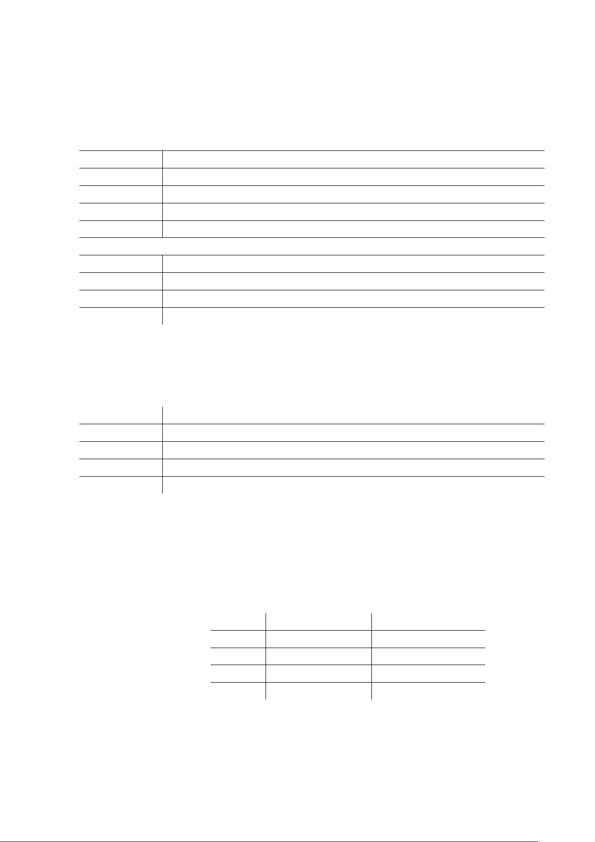
1.3 Specifications
Electrical Specifications
Supply voltage +5 DC
Rise time < 5 ms
Supply voltage r ipple ± 5 %
Supply current
CPU Idle Maximum
E620T
E640T 1.10A / 5.50W 1.55A / 7.75W
Approx. 1.0A / 5.0W
t.b.d.
E660T 1.10A / 5.50W 1.40A / 7.0W
E680T 1.25A / 6.25W 1.65A / 8.25W
TME-CEM-ECO2-Rev0V4.doc Rev 0.4 Page 3
Page 8

Environmental Specificat ions
Operating:
Temperature range 0 … 60 °C (commercial version)
-20 … 60 °C (industrial version)
-40 … 85 °C (extended version)
Temperature change max. 10K / 30 minutes
Humidity (relative) 10 … 90 % (non-condensing)
Pressure 450 … 1100 hPa
Non-Operating/Storage/Transport:
Temperature range -40 … 85 °C
Temperature change max. 10K / 30 minutes
Humidity (relative) 5 … 95 % (non-condensing)
Pressure 450 … 1100 hPa
MTBF
MTBF at 25°C 228.412 hours
Mechanical
Dimensions (LxW) 65 mm x 58 mm
Height 12,4 mm measured from topside of the carrier PCB (with passive
heatsink).
Weight approx. 80 g without h e a ts ink
Mounting 4 mounting holes
TME-CEM-ECO2-Rev0V4.doc Rev 0.4 Page 4
Page 9

Top
Bottom
TME-CEM-ECO2-Rev0V4.doc Rev 0.4 Page 5
Page 10
2 Getting Started
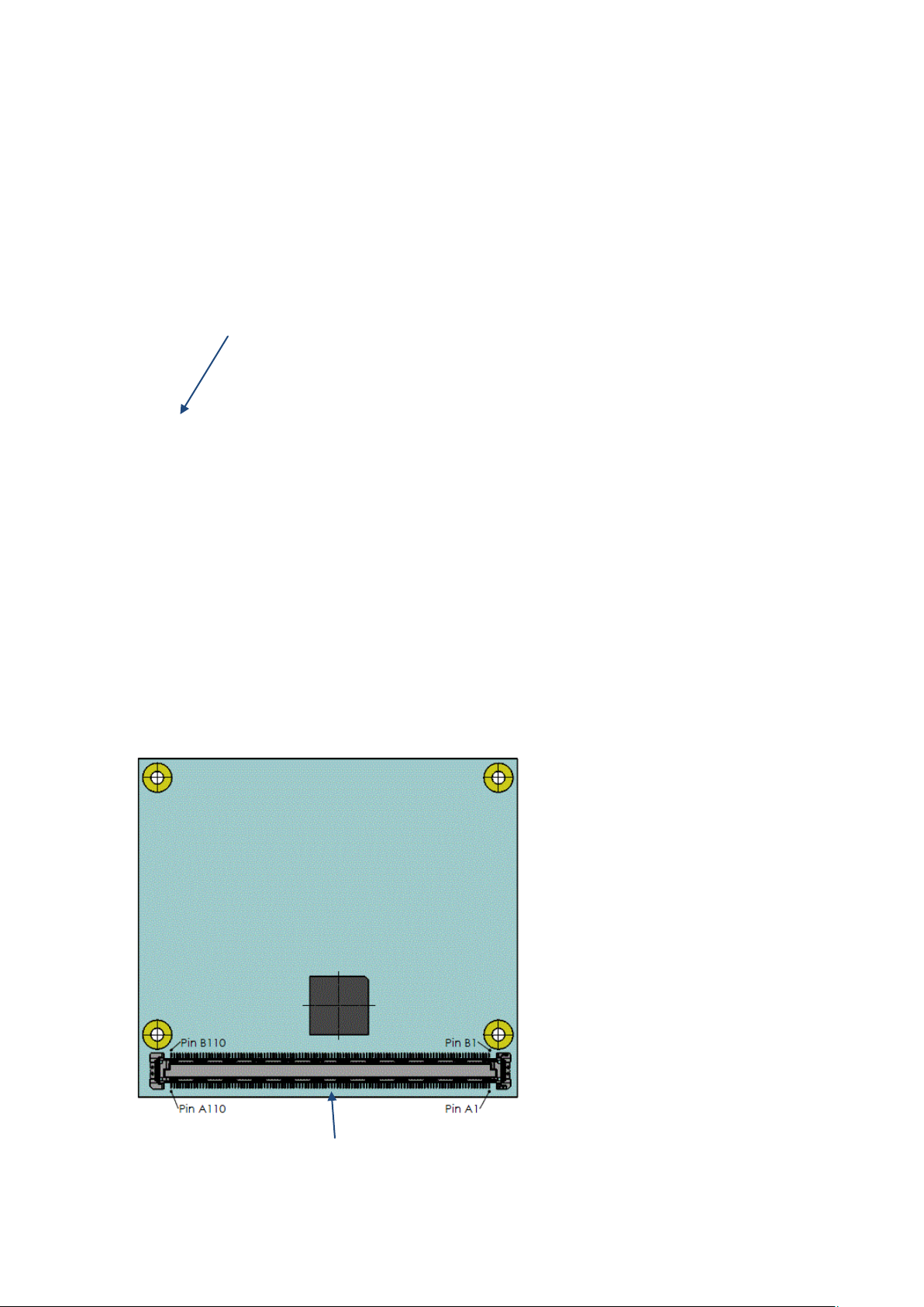
2.1 Connector Loc ations
Except for the CoreExpress connector at the bottom side of the PCB, the CoreExpress-ECO2 has no
connectors.
Top
SPI service connector
Bottom
CoreExpress Connector
TME-CEM-ECO2-Rev0V4.doc Rev 0.4 Page 6
Page 11

2.2 Carrier Board Considerations
The CoreExpress specification de fines two types of connectors for the carrier board, on e with a
height of 5 mm, the other with a height of 8 mm. See the specificat ion for the connector d efinition
and recommended vendor s .
LiPPERT recomm ends using the 8 mm type , since it gives more fr e edom for components on top of
the carrier board and allows for grea ter d is tance between th e two PCB's, which is imp or ta nt for
applications r eq uiring higher vibration tolerance. W hen using the 8 mm connectors, the maxim um
component height on the carrier board (below the CoreExpress-ECO2) can be up to 4 mm. Figure1
shows the details.
Figure 1: Maximum component height with 8 mm connector type
Figure 2: Minimum component height with 5 mm connector type
Note Be carefull with the metal spacers when mounting the board. There is a
possible danger t o c reate a short circ uit with the componen ts located
around the mounting holes. This can damage the board!
TME-CEM-ECO2-Rev0V4.doc Rev 0.4 Page 7
Page 12

2.3 Hardware Setup
Caution B e s ure to follow the EMC sec urity recommendations. Make sure you
are always at th e same potential as th e m od ule.
Unpack the CoreExpress-ECO2 and plug it into your baseboard. Depending on you r final hardware
setup, either mount your cooling solution to the processor and chipset or moun t the complete set of
boards in their enclosure. Connect all necessary peripherals, such as keyboard, mouse, monitor, etc.
to the system.
Switch the power on.
The display shows the BIOS messages. If you want to change th e s ta ndard BIOS settings, press the
<F2> key to enter the BIOS menu. See ch a pter 4.1 for BIOS setup details.
Caution Never operate the CoreExpress-ECO2 without a suitable cooling
solution!
Overheating the processor severely influences th e perfor ma nce and
might even destroy some parts .
Caution Never connect or disconnect peripher a ls like e.g. HDD's or LVDS while
the board's power supply is c on nected and switched on!
If you need to load the BIOS default values, pull the signal BIOS_INIT# (B95) to ground during
startup. This forces the BIOS to load the factory settin gs from FlashPROM .
The CoreExpress-ECO2 boots from CD drive, USB floppy, US B stick, or harddisk . Provided that any of
these is connected a nd contains a valid ope r a ting system image, th e d isplay then shows the boot
screen of your operating sy s tem .
Note Not all USB devices a re suitable to boot the CoreExpress-ECO2 from.
If there are problems, pleas e use another device from different
manufacturer.
TME-CEM-ECO2-Rev0V4.doc Rev 0.4 Page 8
Page 13

3 Module Description
3.1 Processor
There are several ATOM E6xx processor (formerly TunnelCreek) models available with the
CoreExpress-ECO2:
• Intel ATOM processor E620 0.6 GHz
• Intel ATOM processor E640 1.0 GHz
• Intel ATOM processor E660 1.3 GHz
• Intel ATOM processor E680 1.6 GHz
Some of the key features of this processor architecture are:
• The Intel ATOM processor E6xx processor is built using 45-nanometer process techn ology .
• Integrated Graphics E ngine (SDVO, LVDS)
• Memory Controller (32 bit)
• Video Engine (H.264, H.263, MPEG2, MPEG4, VC1, WMV9)
• High Definition Audio Interface
• 4x PCI Express x1 lanes (V 1.1)
• LPC, SPI, SMB, XDP
For further information, please refer to the relev a nt data book.
3.2 Platform Controller Hub
The Platform Controller H ub (PCH) EG20T (for m e r ly TopCliff) provides extensive I/O support.
Functions an d capabilities include i.e.:
• 6x USB 2.0, 1x USB client
• 2x SATA
• 1x Gigabit MAC: RGMII
• 1x SDIO
• 1x CAN
• SPI, I2C
3.3 Watchdog
CoreExpress-ECO2 supports a watchdog function . This function can be configured by the LEMT tool
and let the SMC send a watchdog sign a l ou t w hen the configured time is reached.
The watchdog signal has no access to the m od ule but it could be used on the carrier e.g. to r eset the
module.
Watchdog signal is available on CoreExpress pin B88.
TME-CEM-ECO2-Rev0V4.doc Rev 0.4 Page 9
Page 14

3.4 Graphics-Controller
The CoreExpress-ECO2's graphics controller is integrated in E6xxT CPU. It features a 2D/3D engine
and supports two dedicated display ports.
LVDS
The CoreExpress-ECO2 supports LVDS displays. The specification for LVDS is:
• data format 18/24bits (single channel)
display backlight s upport (Intel´s display power saving technology or optional SMC)
maximum pixel clock rate up to 80 MHz.
maximum resolution up to 1280x768 @ 60 Hz, Minimum pixel clock is 19.75 MHz
SDVO
• Digital Display p or t SDVO for ADD2 car d or SDVO-DVI transmitter on carrier
maximum resolution up to 1280x 1024 @ 85 Hz
maximum pixel clock rate up to 160 MHz
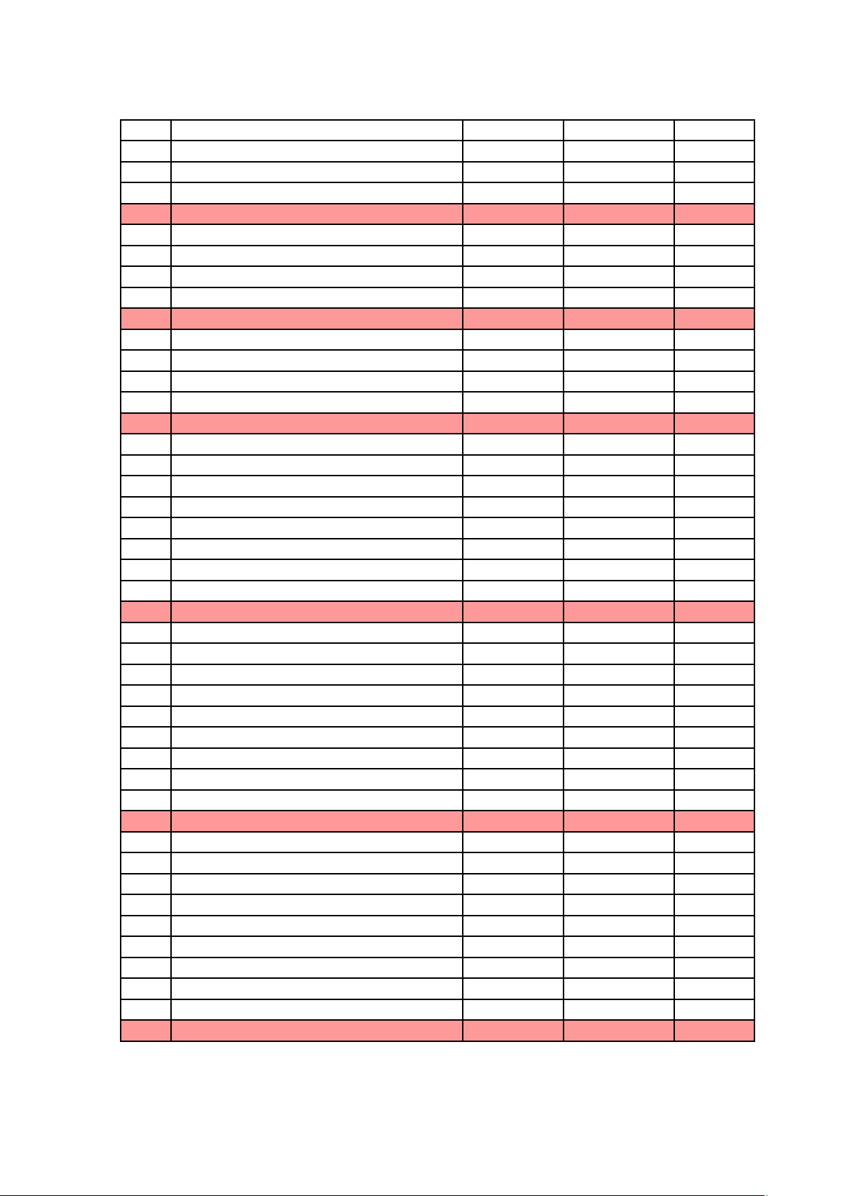
LVDS / SDVO Configuration
The following display mod es a r e s upported:
TME-CEM-ECO2-Rev0V4.doc Rev 0.4 Page 10
Page 15

3.5 Ethernet Controller
MAC Type: PCH internal Gigabit E thernet Media Acces s Controller
Manufacturer: Intel
Connection: RGMII
An Ethernet PHY is needed on the carrier board. A recommended device is the Realtek RTL8211CL
Gigabit Ethernet transc eiv er .
The data transfer between M AC and PHY is via the Reduced Gigabit Media I ndependent Interface
(RGMII) for 1000Base-T, 10Base-T and 100Base-T.
3.6 SATA Ports
There are 2 SATA (Serial Adva nced Technology Attachmen t) G eneration 2 (up to 3.0 Gbps) ports
provided by the PCH EG20T.
3.7 USB 2.0 Ports
The PCH EG20T provides 6 USB 2.0 ports a nd a USB client port.
3.8 Audio Interface
Only the HDA-LINK will be routed to the CoreExpress connector.
3.9 SDIO Interface
The PCH EG20T provides an 8 Bit SDIO interface.
3.10 CAN-Bus Interface
A CAN-bus 2.0B interface with up to 1Mbps is available. A transceiver is still needed to be placed on
the baseboard.
3.11 On Board Power Supply
The on board power supply gen era tes a ll n ec es s a r y voltages from the single supply v ol tage of 5 volts
DC.
3.12 External Power-Button
The board has a power button su pport to initiate tran s ition from S4/S5 to S0.
3.13 Reset-In Signal
The board has a res et button support to restart the system.
TME-CEM-ECO2-Rev0V4.doc Rev 0.4 Page 11
Page 16
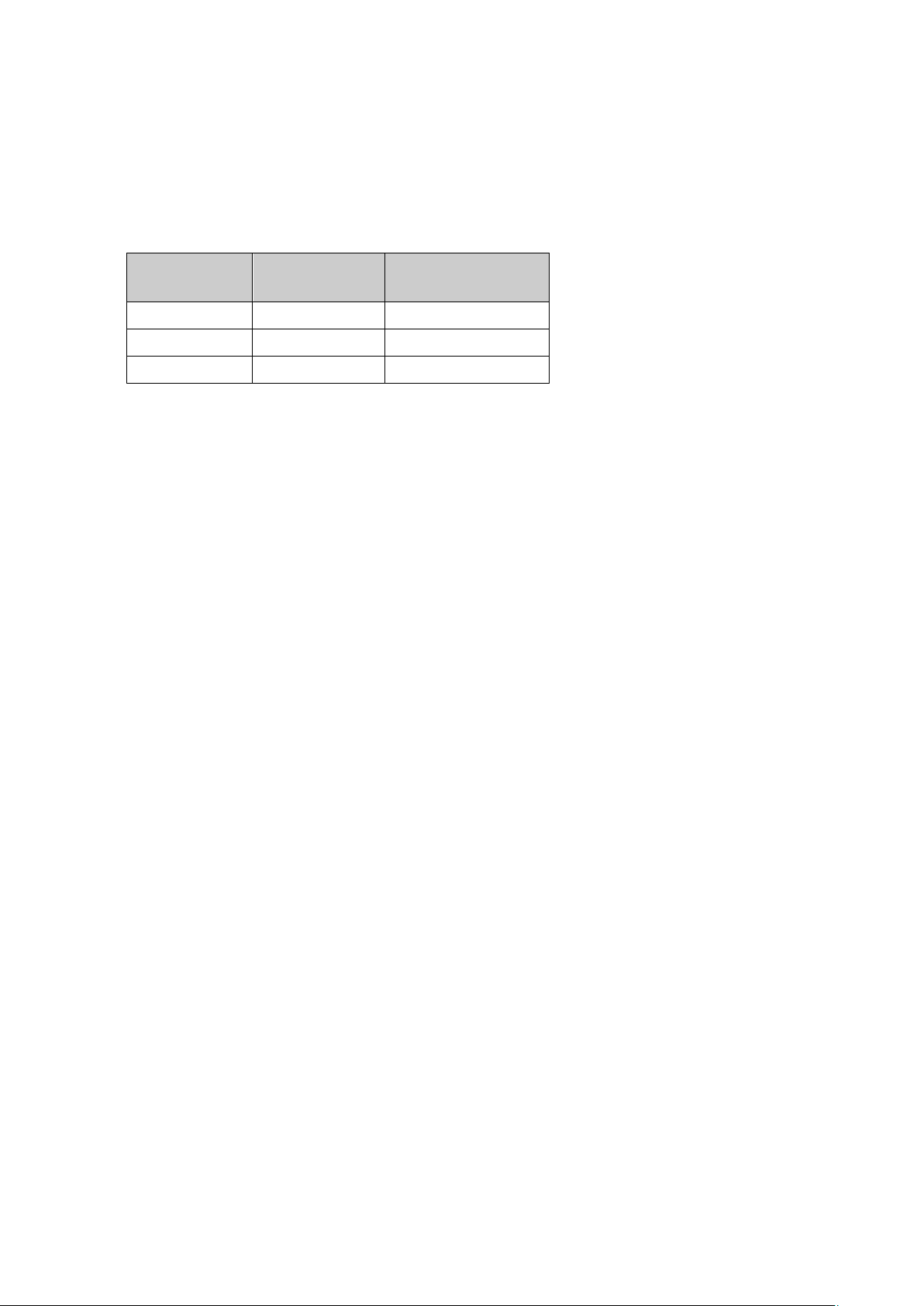
3.14 External Battery
The board supports a RTC that provides a battery of 3.0 V. A typical battery current in suspend
mode is for the late s t ATOM E6xx CPU defined as approx. 24 uA. In S0 m ode th e RTC is powered by
the power supply.
Recommended battery typ es a re:
Battery Type Capacity
(mAh)
CR2032 225 1.1
CR2450 620 2.9
CR2477 1000 4.8
Worst case RTC battery life assuming the processor is always in S5 state.
Worst case life tim e
(years)
3.15 On Board LED indicators
LED1: Status
Color: yellow
Function: blink codes (ON) for diagnostics
LED2: Suspend mode (S3-LED)
Color: yellow
Function: Board is in S3 suspend mode (ON)
TME-CEM-ECO2-Rev0V4.doc Rev 0.4 Page 12
Page 17
A3
PCIE_TXAp
PCIexpress
AC coupled
yes
A6
GND
POWER
0V
no
A7
PCIE_TXBn
PCIexpress
AC coupled
yes
A11
GND (connected to meta l shroud)
POWER
0V
no
A15
PCIE_TXDp (w/o EG20T available)
PCIexpress
AC coupled
yes
A18
CLKREQC#
PCIexpress
3.3V
No
A19
SDVO_CLK#
SDVO
AC coupled
Yes
A23
SDVO_GREEN#
SDVO
AC coupled
Yes
A27
SDVO_RED
SDVO
AC coupled
Yes
A30
LA_DATA0n
LVDS
Low voltage
Yes
A31
GND (connected to meta l shroud)
POWER
0V
No
A35
LA_DATA3n
LVDS
Low voltage
Yes
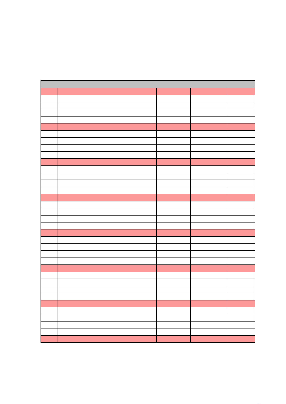
3.16 CoreExpress Bus Interface, V2.1
CoreExpress Connector
Connector Part Number: Tyco 3-6316490-6 or equivalent
Pin# Signal Name Bus Voltage Leve Diff-Sig
A1 GND (connecte d to m e tal shroud) POWER 0V no
A2 PCIE_TXAn PCIexpress AC coupled yes
A4 PCIE_CLKAn PCIexpress 3.3V yes
A5 PCIE_CLKAp PCIexpress 3.3V yes
A8 PCIE_TXBp PCIexpress AC coupled yes
A9 PCIE_TXCn PCIexpress AC coupled yes
A10 PCIE_TXCp PCIexpress AC coupled yes
A12 PCIE_CLKCn PCIexpress AC coupled yes
A13 PCIE_CLKCp PCIexpress AC coupled yes
A14 PCIE_TXDn (w/o EG20T available) PCIexpress AC coupled yes
A16 GND POWER 0V no
A17 CLKREQA# PCIexpress 3.3V no
A20 SDVO_CLK SDVO AC coupled Yes
A21 GND (connected to meta l shroud) POWER 0V No
A22 SDVO_GREEN SDVO AC coupled Yes
A24 SDVO_TVCLKIN# SDVO AC coupled Yes
A25 SDVO_TVCLKIN SDVO AC coupled Yes
A26 GND POWER 0V No
A28 SDVO_RED# SDVO AC coupled Yes
A29 LA_DATA0p LVDS Low voltage Yes
A32 LA_DATA2p LVDS Low voltage Yes
A33 LA_DATA2n LVDS Low voltage Yes
A34 LA_DATA3p LVDS Low voltage Yes
A36 GND POWER 0V No
TME-CEM-ECO2-Rev0V4.doc Rev 0.4 Page 13
Page 18
A39
USB_Ap
USB2.0
Low voltage
Yes
A43
USB_Cn
USB2.0
Low voltage
Yes
A47
USB_Gp (n.c.)
USB2.0
Low voltage
Yes
A48
USB_Gn (n.c.)
USB2.0
Low voltage
Yes
A51
GND (connected to metal shr oud)
POWER
0V
No
A55
RGMII-TD3
RGMII
2.5 V
no
A59
SATA_LED#
SATA2
3.3V
no
A60
GND (connected to meta l shroud)
POWER
0V
no
A63
SATA_RXAp
SATA2
AC coupled
yes
A67
Reserved for future use
yes
A71
RGMII-TXC
RGMII
2.5 V
no
A75
RGMII-MDIO
RGMII
2.5 V
no
A79
LPC_FRAME#
LPC
3.3V
no
A37 L_DDC_DATA LVDS 3.3V No
A38 L_DDC_CLK LVDS 3.3V No
A40 USB_An USB2.0 Low voltage Yes
A41 GND (connected to meta l shroud) POWER 0V No
A42 USB_Cp USB2.0 Low voltage Yes
A44 USB_Ep USB2.0 Low volta ge Yes
A45 USB_En USB2.0 Low v oltage Yes
A46 GND POWER 0V No
A49 USB_A/B_OC# USB2.0 3.3V No
A50 USB_E/F_OC# USB2.0 3.3V No
A52 RGMII-TD0 RGMII 2.5 V No
A53 RGMII-TD1 RGMII 2.5 V No
A54 RGMII-TD2 RGMII 2.5 V no
A56 SMB_CLK SMB 3.3V no
A57 SMB_DATA SMB 3.3V no
A58 SMB_ALERT# SMB 3.3V no
A61 SATA_TXAp SATA2 AC coupled yes
A62 SATA_TXAn SATA2 AC coupled yes
A64 SATA_RXAn SATA2 AC coupled yes
A65 GND POWER 0V no
A66 Reserved for future use yes
A68 Reserved for future use yes
A69 Reserved for future use yes
A70 GND (connected to meta l shroud) POWER 0V no
A72 RGMII-TXCTL RGMII 2.5 V no
A73 NC no
A74 RGMII-MDC RGMII 2.5 V no
A76 LPC_AD3 LPC 3.3V no
A77 LPC_AD1 LPC 3.3V no
A78 LPC_AD0 LPC 3.3V no
A80 GND (connected to meta l shroud) POWER 0V no
TME-CEM-ECO2-Rev0V4.doc Rev 0.4 Page 14
Page 19

A83
SD0_CLK
SDIO 8Bit
3.3V
no
A87
SD0_DATA6
SDIO 8Bit
3.3V
no
A91
HDA_DOCK_EN#
HD Audio
1.8V or 3.3V
no
A95
NC
no
A99
GPIO3
CONTROL
3.3V
no
A103
WAKE#
CONTROL
3.3V
no
A107
+5V0
POWER
5V
no
A81 SD0_WP SDIO 8Bit 3.3V no
A82 SD0_CD# SDIO 8Bit 3.3V no
A84 SD0_DATA1 SDIO 8Bit 3.3V no
A85 SD0_DATA3 SDIO 8Bit 3.3V no
A86 SD0_DATA5 SDIO 8Bit 3.3V no
A88 L_CTLB_DATA LVDS 3.3V no
A89 L_CTLB_CLK LVDS 3.3V no
A90 GND (connected to meta l shroud) POWER 0V no
A92 HDA_SDATAIN1 HD Audio 1.8V or 3.3V no
A93 HDA_SDATAOUT HD Audio 1.8V or 3.3V no
A94 HDA_RST# HD Audio 1.8V or 3.3V no
A96 GPIO0 CONTROL 3.3V no
A97 GPIO1 CONTROL 3.3V no
A98 GPIO2 CONTROL 3.3V no
A100 GND (connected to meta l shroud) POWER 0V no
A101 RESET_OUT# CONTROL 3.3V no
A102 RESET_IN# CONTROL 3.3V no
A104 +5V0 POWER 5V no
A105 +5V0 POWER 5V no
A106 +5V0 POWER 5V no
A108 +5V0 POWER 5V no
A109 +5V0 POWER 5V no
A110 GND (connected to meta l shroud) POWER 0V no
TME-CEM-ECO2-Rev0V4.doc Rev 0.4 Page 15
Page 20

B3
PCIE_RXAp
PCIexpress
AC coupled
yes
B7
PCIE_RXBn
PCIexpress
AC coupled
yes
B11
GND (connected to metal shr oud)
POWER
0V
no
B12
PCIE_CLKDn (w/o EG20T available)
PCIexpress
3.3V
yes
B15
PCIE_RXDp (w/o EG20T available)
PCIexpress
AC coupled
yes
B19
SDVO_INT#
SDVO
AC coupled
yes
B25
SDVO_STALL#
SDVO
AC coupled
yes
B29
LA_DATA1p
LVDS
Low voltage
yes
B33
LA_CLKn
LVDS
Low voltage
yes
B37
L_VDDEN
LVDS
3.3V
no
B41
GND (connected to meta l shroud)
POWER
0V
no
B45
USB_Fn
USB2.0
Low voltage
yes
B1 GND (connecte d to m e tal shroud) POWER 0V no
B2 PCIE_RXAn PCIexpress AC coupled yes
B4 PCIE_CLKBn PCIexpress 3.3V yes
B5 PCIE_CLKBp PCIexpress 3.3V yes
B6 GND POWER 0V no
B8 PCIE_RXBp PCIexpress AC coupled yes
B9 PCIE_RXCn PCIexpress AC coupled yes
B10 PCIE_RXCp PCIexpress AC coupled yes
B13 PCIE_CLKDp (w/o EG20T available) PCIexpress 3.3V yes
B14 PCIE_RXDn (w/o EG20T available) PCIexpress AC coupled yes
B16 GND POWER 0V no
B17 CLKREQB# PCIexpress 3.3V no
B18 CLKREQD# (w/o EG20T available) PCIexpress 3.3V no
B20 SDVO_INT SDVO AC coupled yes
B21 GND (connected to meta l shroud) POWER 0V no
B22 SDVO_BLUE SDVO AC coupled yes
B23 SDVO_BLUE# SDVO AC coupled yes
B24 SDVO_STALL SDVO AC c ou pled yes
B26 GND POWER 0V no
B27 SDVO_CTRL_CLK SDVO AC coupled yes
B28 SDVO_CTRL_DAT SDVO AC coupled yes
B30 LA_DATA1n LVDS Low voltage yes
B31 GND (connected to meta l shroud) POWER 0V no
B32 LA_CLKp LVDS Low voltage yes
B34 L_BKLTCTL LVDS 3.3V no
B35 L_BKLTEN LVDS 3.3V no
B36 L_DETECT LVDS 3.3V no
B38 USB_C_DEVICE USB2.0 3.3V no
B39 USB_Bp USB2.0 Low voltage yes
B40 USB_Bn USB2.0 Low voltage yes
B42 USB_Dp USB2.0 Low voltage yes
B43 USB_Dn USB2.0 Low voltage yes
B44 USB_Fp USB2.0 Low voltag e yes
B46 GND POWER 0V no
TME-CEM-ECO2-Rev0V4.doc Rev 0.4 Page 16
Page 21

B49
USB_C/D_OC#
USB2.0
3.3V
no
B53
RGMII-RD1
RGMII
2.5 V
no
B54
RGMII-RD2
RGMII
2.5 V
no
B57
SPI_MOSI (IOH)
SPI
3.3V
no
B61
SATA_TXBp
SATA2
AC coupled
yes
B65
GND
POWER
0V
no
B66
Reserved for future use
B69
Reserved for future use
B73
NC
NC
NC
no
B77
LPC_CLK_OUT1
LPC
3.3V
no
B81
SD0_DATA7
SDIO 8Bit
3.3V
no
B85
SD0_DATA4
SDIO 8Bit
3.3V
no
B89
HDA_SPKR
HD Audio
3.3V
no
B90
GND (connected to meta l shroud)
POWER
0V
no
B47 USB_Hp (Client) USB2.0 Low volta ge yes
B48 USB_Hn (Client) USB2.0 Low voltage yes
B50 USB_G/H_OC# USB2.0 3.3V no
B51 GND (connected to metal shroud) POWER 0V no
B52 RGMII-RD0 RGMII 2.5 V no
B55 RGMII-RD3 RGMII 2.5 V no
B56 SPI_MISO (IOH) SPI 3.3V no
B58 SPI_CS# (IOH) SPI 3.3V no
B59 SPI_CLK (IOH) SPI 3.3V no
B60 GND (connected to meta l shroud) POWER 0V no
B62 SATA_TXBn SATA2 AC coupled yes
B63 SATA_RXBp SATA2 AC coupled yes
B64 SATA_RXBn SATA2 AC coupled yes
B67 Reserved for future use
B68 Reserved for future use
B70 GND (connected to meta l shroud) POWER 0V no
B71 RGMII-RXC RGMII 2.5 V yes
B72 RGMII-RXCTL RGMII 2.5 V yes
B74 CAN_TX CAN 3.3V yes
B75 CAN_RX CAN 3.3V yes
B76 LPC_CLK_OUT2 LPC 3.3V no
B78 LPC_SERIRQ LPC 3.3V no
B79 LPC_AD2 LPC 3.3V no
B80 GND (connected to meta l shroud) POWER 0V no
B82 SD0_PWR# SDIO 8Bit 3.3V no
B83 SD0_DATA2 SDIO 8Bit 3.3V no
B84 SD0_LED SDIO 8Bit 3.3V no
B86 SD0_DATA0 SDIO 8Bit 3.3V no
B87 SD0_CMD SDIO 8Bit 3.3V no
B88 WD_OUT CONTROL 3.3V no
TME-CEM-ECO2-Rev0V4.doc Rev 0.4 Page 17
Page 22

B93
HDA_SDATAIN0
HD Audio
1.8V or 3.3V
no
B97
PS_ON
CONTROL
3.3 V
no
B101
SUS_S4/5#
CONTROL
3.3 V
no
B105
+5V0
POWER
5V
no
B109
+5V0
POWER
5V
no
B91 HDA_BITCLK HD Audio 1.8V or 3.3V no
B92 HDA_DOCK_RST# HD Audio 1.8V or 3.3V no
B94 HDA_SYNC HD Audio 1.8V or 3.3V no
B95 BIOS_INIT# CONTROL 3.3 V no
B96 PWR_GOOD CONTROL 3.3 V no
B98 PWR_BTN# CONTROL 3.3 V no
B99 SUS_S3# CONTROL 3.3 V no
B100 GND (connected to metal shroud) POWER 0V no
B102 BIOS_DISABLE# CONTROL 3.3 V no
B103 BAT_IN POWER 2.8 – 3.3 V no
B104 +5V0-ALWAYS POWER 5V no
B106 +5V0 POWER 5V no
B107 +5V0 POWER 5V no
B108 +5V0 POWER 5V no
B110 GND (connected to metal shroud) POWER 0V no
(NC): not connected
TME-CEM-ECO2-Rev0V4.doc Rev 0.4 Page 18
Page 23

4 Using the Module
4.1 BIOS
The CoreExpress-ECO2 is delivered with a Phoenix-Technology EFI-BIOS. The default setting
guarantees a “ready to run” s ystem, even without a BIOS setup bac kup battery.
The BIOS is located in a flash prom and can be easily updated on board with sof tware or an SPI programming adapter.
All changes in the setup of the BIOS are stored in the CMOS RAM of the real time clock. A copy of
the CMOS RAM ex c luding date and time data is s tored in the flash ROM. This means that ev e n if the
backup battery r uns out of power, th e CMOS settings are not lost. Only date and time will be set to
their default value.
Configuring the Phoenix BIOS
Pressing the <F2> key on powe r up starts the BIO S setu p utility.
Field Selection
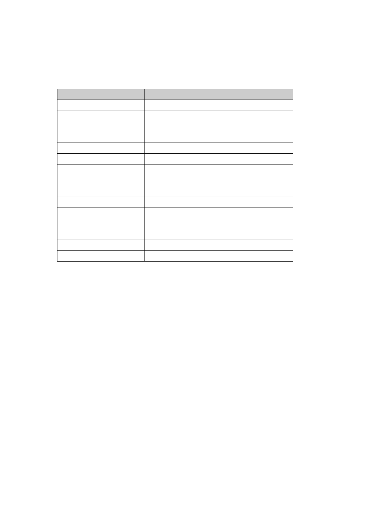
To move between fields in Setup, use the keys listed below:
Key Function
, , ,
+, - Selects next/previous values in fields
Enter Go to the submenu for th e fie ld
Esc To previous field then to exit menu
TME-CEM-ECO2-Rev0V4.doc Rev 0.4 Page 19
Move between fields
Page 24

Trouble Shooting BIOS Settings
It may happen that the BIOS is so badly c onfigured that the CoreExpress-ECO2 does not start at al l.
To repair this, the default values of the BIOS can be automatic ally loaded at boot time. This is
commanded by pulling CoreExpress pin B95 to ground before t he s ystem is turned on. Holding this
level and turning the system on loads the default values.
4.2 Drivers
There are drivers for different operating systems for sound, Ethernet and graphics controller
available.
These drivers can be downloaded from LiPPERT's website http://www.lippertembedded.com.
For installation follow the ins tr uctions that come w ith the drivers.
TME-CEM-ECO2-Rev0V4.doc Rev 0.4 Page 20
Page 25

4.3 LEMT Functions
The onboard Microcontroll er im plements power sequencin g a nd LEMT (LiPPERT Enhanced
Management Technolog y) functionality . The microcontroller communicates via the System
Management Bus with the CPU/Chip s e t. The following functions are implemented:
• Total oper a ting hours counter
Counts the number of hours the module has been run in minutes.
• On-time minutes counter
Counts the seconds since last system start.
• Temperature monitoring of CPU and Board temperature
Min. and max. temperature values of CPU and board are stored in flash.
• Power cycles counter
• Watchdog Timer
Set / Reset / Disable Watchdog T imer .
• System Restart Cause
Power loss / Watchdog / External Reset.
• Fail-Safe-BIOS Support
In case of a Boot failure, hardware signals tells external logic to boot from a Fail-Safe-BIOS.
• Flash area
1kB Flash area for customer data
• Protected Flash area
128 Bytes for Keys, ID's, etc. can stored in a write- and clear-protectable region.
• Manufactur ing information
Part number / Serial number / BIOS version / Test date
• Current Power consumption and average
Please refer to the LEMT documentati on for the usage of th e L EMT functions.
TME-CEM-ECO2-Rev0V4.doc Rev 0.4 Page 21
Page 26

4.4 Troubleshooting
PROBLEM: The system will not com e up at all, the display is b la nk and the computer does not make
any beep sounds from the speaker.
First steps if the B oa r d does not boot:
• Check the pow e r c onnectors to the board, m onitor and additional devices.
• Are all cables plugged on the correc t c onnector and in th e correct orientation? T he board
may not boot if some of the cables are not plugged in correctly!
• Check the power supply. Is th e s upply voltage correct for the board? If you are not sure,
read the manual. Try plugging in a different power supply or multi-meter to check th e
power a wrong supply voltage ca n easily FRY a computer and other electrical devices.
• Is your display ok? Is the monitor power ed on? Is the monitor' s video cable plugged into
the video connector ? Double-check the brightness and con tr ast settings. Plu g the m onitor
into another compu te r if possible to verif y the monitor isn' t the problem.
• Apply power to the board wh ile pulling down the BIOS_INIT# signal at pin B95. This will
load the manufacturer BIOS defaults.
• Remove all additional devices from the system. Only th e p r oc e s s or board, power su p ply,
monitor and the keyboard should remain in the system.
• If all else has fa iled , replace the CPU Board itself.
• If system comes up then load at first the O P TIMIZED DEFAULTS in the BIOS setup and
reboot.
TME-CEM-ECO2-Rev0V4.doc Rev 0.4 Page 22
Page 27

5 Address Maps
This section describes the layout of the CPU memory and I/O address spaces.
Note Depending on enabled or disabled fun c tion s in the BIOS, other or
5.1 Memory Address Map
Address Range (Hex) Description
Legacy Address Ra n ge (0 to 1 MB)
00000000 – 0009FFFF DOS_DRAM
000A0000 – 000DFFFF Legacy V ideo (VGA)
000E0000 – 000EFFFF PAM
more resources may be used
000F0000 – 000FFFFF PAM
000F0000 – 000FFFFF BIOS (LPC)
000E0000 – 000FFFFF LPC (Provided PAM is not enabled)
Main Memory (1MB to TOM)
Variable – Variable TSEG
Variable – Variable Graphics
PCI Configuration Space (2GB to 4G B )
FEC00000 – FEC00040 IOxAPIC
FED00000 – FED003FF HPET (High Performance Ev ent Timer)
FED04000 – FED4BFFF TPM1.2 (LPC)
FFC00000 – FFFFFFFF
High BIOS (The Chipset Microcode (CMC) base
address lives within the LPC space and
consumes 64 kB of space. Make sure to avoid
using the same starting address for other
LPC devices in the system. )
TME-CEM-ECO2-Rev0V4.doc Rev 0.4 Page 23
Page 28
5.2 I/O Address Map
The system chip set implements a number of registers in I/O a ddr es s s pa c e. Th es e r egi sters occupy
the following map in the I/O space.
Address Range (Hex) Description
20h-3Ch 8259 Master
40h-53h 8254
61h-67h NMI Controller
70h-77h NMI and RTC
84h-86h Internal
88h Internal
8Ch-8Eh Internal
A0h-ACh 8259 Slave
B0h 8259 8259 Slave
B2h-B3h Power Management
B4h-BCh 8259 Slave
3B0h-3BBh VGA
3C0h-3DFh VGA
CF8h, CFCh Internal
CF9h Reset Generator
TME-CEM-ECO2-Rev0V4.doc Rev 0.4 Page 24
Page 29

5.3 Interrupts
IRQ System Resource
0 Timer
1 Keyboard
2 Not used
3 Not used
4 Not used
5 Not used
6 Not used
7 Not used
8 System CMOS / Real T im e Cloc k
9 MS-ACPI conform System
10 Not used
11 Not used
12 Not used
13 Math coprocessor
14 Primar y IDE Controller
15 Not used
Note Depending on the BIOS settings, it’s poss ible to reserve
several IRQ’s for other system devices on the carrier board
TME-CEM-ECO2-Rev0V4.doc Rev 0.4 Page 25
Page 30

5.4 DMA Channels
DMA System Resource
0 User available
1 User available
2 User available
3 User available
4 DMA Controller
5 User Available
6 User Available
7 User Available
TME-CEM-ECO2-Rev0V4.doc Rev 0.4 Page 26
Page 31

6 Timings
The following timin gs are for CoreExpress-ECO2 based on PC B rev. 407-0003-10 and SMC firmware
version 1V4.
6.1 StartUp
TME-CEM-ECO2-Rev0V4.doc Rev 0.4 Page 27
Page 32

6.2 WakeUp
6.3 Reset
TME-CEM-ECO2-Rev0V4.doc Rev 0.4 Page 28
Page 33

Appendix A, Further Resources
www.lippertembedded.com
Where the CoreExpress-ECO2 comes from.
www.intel.com
Manufacturer of the used CPU, Chipset and Ethernet-Controller.
www.pcisig.com
Where PCI Express specification was defined.
www.sff-sig.org
Where CoreExpress specification was defined.
www.usb.org
Universal Serial Bus (USB) connects computers, peripherals and more.
www.smbus.org
SMBus is the System Managemen t Bus defined by Intel.
www.sata-io.org
All about Serial AT A.
http://www.phoenix.com
Additional BIOS information.
TME-CEM-ECO2-Rev0V4.doc Rev 0.4 Appendix A
 Loading...