

Page 1
BattMan
Smart Battery Management
Reference System
Manual Revision: 2.00
Revision Date: October 19, 2010
Part Number: 50-1J031-1000
Page 2

Revision History
Release Date Change
2.00 2010/10/19 Initial Release
Page 2
BattMan User’s Guide
Page 3

Preface
Copyright 2010 ADLINK Technology, Inc.
This document contains proprietary information protected by copyright. All rights are
reserved. No part of this manual may be reproduced by any mechanical, electronic, or other
means in any form without prior written permission of the manufacturer.
Disclaimer
The information in this document is subject to change without prior notice in order to improve
reliability, design, and function and does not represent a commitment on the part of the
manufacturer.
In no event will the manufacturer be liable for direct, indirect, special, incidental, or
consequential damages arising out of the use or inability to use the product or documentation,
even if advised of the possibility of such damages.
Trademarks
AMIBIOS®8 is a registered trademark of American Megatrends, Inc. COM Express™, and
PICMG® are registered trademarks of the PCI Industrial Computer Manufacturers Group.
Product names mentioned herein are used for identification purposes only and may be
trademarks and/or registered trademarks of their respective companies.
Quality Standards
ADLINK is certified to be in conformance with ISO 9001 quality management and ISO-14001
environmental management systems, and has addtional TL 9000 certification to meet the
supply chain quality requirements of the global communications industry.
BattMan User’s Guide Page 3
Page 3Express-IA533 User’s Manual Page 3Express-IA533 User’s ManualExpress-CB User’s Manual Page 3
Page 4

Environmental Responsibility (RoHS & WEEE)
ADLINK is committed to fulfill its social responsibility to global environmental preservation
through compliance with the European Union's Restriction of Hazardous Substances (RoHS)
directive and Waste Electrical and Electronic Equipment (WEEE) directive. Environmental
protection is a top priority for ADLINK. We have enforced measures to ensure that our
products, manufacturing processes, components, and raw materials have as little impact on
the environment as possible. When products are at their end of life, our customers are
encouraged to dispose of them in accordance with the product disposal and/or recovery
programs prescribed by their nation or company.
Electrostatic Sensitive Device (ESD)
Always ground yourself to remove any static charge before touching the module or carrier
board. Modern electronic devices are very sensitive to static electric charges. Use a
grounding wrist strap at all times. Place all electronic components on a static-dissipative
surface or in a static-shielded bag when they are not installed in a chassis.
Page 4
BattMan User’s Guide
Page 5

Conventions
Take note of the following conventions used throughout this manual to make sure that users
perform certain tasks and instructions properly.
Additional information, aids, and tips that help users perform tasks.
Information to prevent minor physical injury, component damage, data loss,
and/or program corruption when trying to complete a task.
Information to prevent serious physical injury, component damage, data
loss, and/or program corruption when trying to complete a specific task.
BattMan User’s Guide Page 5
Page 5Express-IA533 User’s Manual Page 5Express-IA533 User’s ManualExpress-CB User’s Manual Page 5
Page 6

Important Safety Instructions
For user safety, please read and follow all instructions, warnings, cautions, and notes
marked in this manual and on the associated equipment before handling/operating the
equipment.
f Read these safety instructions carefully.
f Keep this user’s manual for future reference.
f Read the specifications section of this manual for detailed information on the operating
environment of this equipment.
f When installing/mounting or uninstalling/removing equipment:
- Turn off power and unplug any power cords/cables.
f To avoid electrical shock and/or damage to equipment:
- Keep equipment away from water or liquid sources;
- Keep equipment away from high heat or high humidity;
- Keep equipment properly ventilated (do not block or cover ventilation openings);
- Make sure to use recommended voltage and power source settings;
- Always install and operate equipment near an easily accessible electrical socket-outlet;
- Secure the power cord (do not place any object on/over the power cord);
- Only install/attach and operate equipment on stable surfaces and/or recommended
mountings; and,
- If the equipment will not be used for long periods of time, turn off and unplug the
equipment from its power source.
f Never attempt to fix the equipment. Equipment should only be serviced by qualified
personnel.
Page 6
f A Lithium-type battery may be provided for uninterrupted, backup or emergency power.
Risk of explosion if battery is replaced by an incorrect type. Dispose of used batteries
according to the instructions.
f Equipment must be serviced by authorized technicians when:
- The power cord or plug is damaged;
- Liquid has penetrated the equipment;
- It has been exposed to high humidity/moisture;
- It is not functioning or does not function according to the user’s manual;
- It has been dropped and/or damaged; and/or,
- It has an obvious sign of breakage.
BattMan User’s Guide
Page 7

Technical Support
Contact us should you require any service or assistance.
ADLINK Technology, Inc.
Address: 9F, No.166 Jian Yi Road, Chungho City,
Taipei County 235, Taiwan
קᗼխࡉؑ৬ԫሁ 166 ᇆ 9 ᑔ
Tel: +886-2-8226-5877
Fax: +886-2-8226-5717
Email: service@adlinktech.com
Ampro ADLINK Technology, Inc.
Address: 5215 Hellyer Avenue, #110, San Jose, CA 95138, USA
Tel: +1-408-360-0200
Toll Free: +1-800-966-5200 (USA only)
Fax: +1-408-360-0222
Email: info@adlinktech.com
ADLINK Technology (China) Co., Ltd.
Address: Ϟ⍋Ꮦ⌺ϰᮄᓴ∳催⾥ᡔು㢇䏃 300 ো(201203)
300 Fang Chun Rd., Zhangjiang Hi-Tech Park,
Pudong New Area, Shanghai, 201203 China
Tel: +86-21-5132-8988
Fax: +86-21-5132-3588
Email: market@adlinktech.com
ADLINK Technology Beijing
Address: ࣫ҀᏖ⍋⎔Ϟഄϰ䏃 1 োⲜ߯ࡼ E ᑻ 801 ᅸ(100085)
Rm. 801, Power Creative E, No. 1, B/D
Shang Di East Rd., Beijing, 100085 China
Tel: +86-10-5885-8666
Fax: +86-10-5885-8625
Email: market@adlinktech.com
ADLINK Technology Shenzhen
Address: ⏅ഇᏖቅ⾥ᡔು催ᮄϗ䘧᭄ᄫᡔᴃು
A1 2 ὐ C (518057)
2F, C Block, Bldg. A1, Cyber-Tech Zone, Gao Xin Ave. Sec. 7,
High-Tech Industrial Park S., Shenzhen, 518054 China
Tel: +86-755-2643-4858
Fax: +86-755-2664-6353
Email: market@adlinktech.com
BattMan User’s Guide Page 7
Page 7Express-IA533 User’s Manual Page 7Express-IA533 User’s ManualExpress-CB User’s Manual Page 7
Page 8

ADLINK Technology (Europe) GmbH
Address: Nord Carree 3, 40477 Duesseldorf, Germany
Tel: +49-211-495-5552
Fax: +49-211-495-5557
Email: emea@adlinktech.com
ADLINK Technology, Inc. (French Liaison Office)
Address: 15 rue Emile Baudot, 91300 Massy CEDEX, France
Tel: +33 (0) 1 60 12 35 66
Fax: +33 (0) 1 60 12 35 66
Email: france@adlinktech.com
ADLINK Technology Japan Corporation
Address: 151-0072 ᧲ㇺ⼱ᐈ䊱⼱㩷
1-1-2 ᦺᣣ↢ᐈ䊱⼱䊎䊦 8F
Asahiseimei Hatagaya Bldg. 8F
1-1-2 Hatagaya, Shibuya-ku, Tokyo 151-0072, Japan
Tel: +81-3-4455-3722
Fax: +81-3-5333-6040
Email: japan@adlinktech.com
ADLINK Technology, Inc. (Korean Liaison Office)
Address: 昢殾柢 昢爎割 昢爎壟 1506-25 穢壊 B/D 2 猻
2F, Hando B/D, 1506-25, Seocho-Dong, Seocho-Gu,
Seoul 137-070, Korea
Tel: +82-2-2057-0565
Fax: +82-2-2057-0563
Email: korea@adlinktech.com
ADLINK Technology Singapore Pte. Ltd.
Address: 84 Genting Lane #07-02A, Cityneon Design Centre,
Singapore 349584
Tel: +65-6844-2261
Fax: +65-6844-2263
Email: singapore@adlinktech.com
ADLINK Technology Singapore Pte. Ltd. (Indian Liaison Office)
Address: No. 1357, "Anupama", Sri Aurobindo Marg, 9th Cross,
JP Nagar Phase I, Bangalore - 560078, India
Tel: +91-80-65605817
Fax: +91-80-22443548
Email: india@adlinktech.com
Page 8
BattMan User’s Guide
Page 9

Table of Contents
Preface ............................................................................................................................3
Important Safety Instructions ..........................................................................................................6
Technical Support ............................................................................................................................7
1 Introduction.............................................................................................................11
2 Electrical Specification ...........................................................................................12
2.1 Input Power ........................................................................................................................12
2.2 Output Power .....................................................................................................................12
2.3 Functional Characteristics ................................................................................................. 12
3 Functional Block Diagram ......................................................................................13
4 Mechanical Dimensions..........................................................................................14
5 Component Locations ............................................................................................15
6 Module Configuration .............................................................................................16
6.1 Operating Mode .................................................................................................................16
6.2 Charger Enable/Disable ....................................................................................................16
6.3 Indicator LEDs ....................................................................................................................17
6.4 Battery Settings..................................................................................................................18
7 Connector Pin Assignments ..................................................................................19
7. 1 ATX Output Power to Host System Connector (CNX2) ....................................................19
7. 2 Auxiliary Output Power Connector (CNX1)....................................................................... 1 9
7.3 Host Control/Monitor Connector (CN6).............................................................................19
7. 4 Battery 1 Connector (CNX3)..............................................................................................20
7. 5 Battery 2 Connector (CNX4)..............................................................................................20
8 Getting Started........................................................................................................21
8.1 Unpacking the Contents ....................................................................................................21
8.2 Cable Connections ............................................................................................................22
8.3 Windows OS Interface ....................................................................................................... 24
9 References ..............................................................................................................26
BattMan User’s Guide Page 9
Page 9Express-IA533 User’s Manual Page 9Express-IA533 User’s ManualExpress-CB User’s Manual Page 9
Page 10

This page intentionally left blank.
Page 10
BattMan User’s Guide
Page 11

1 Introduction
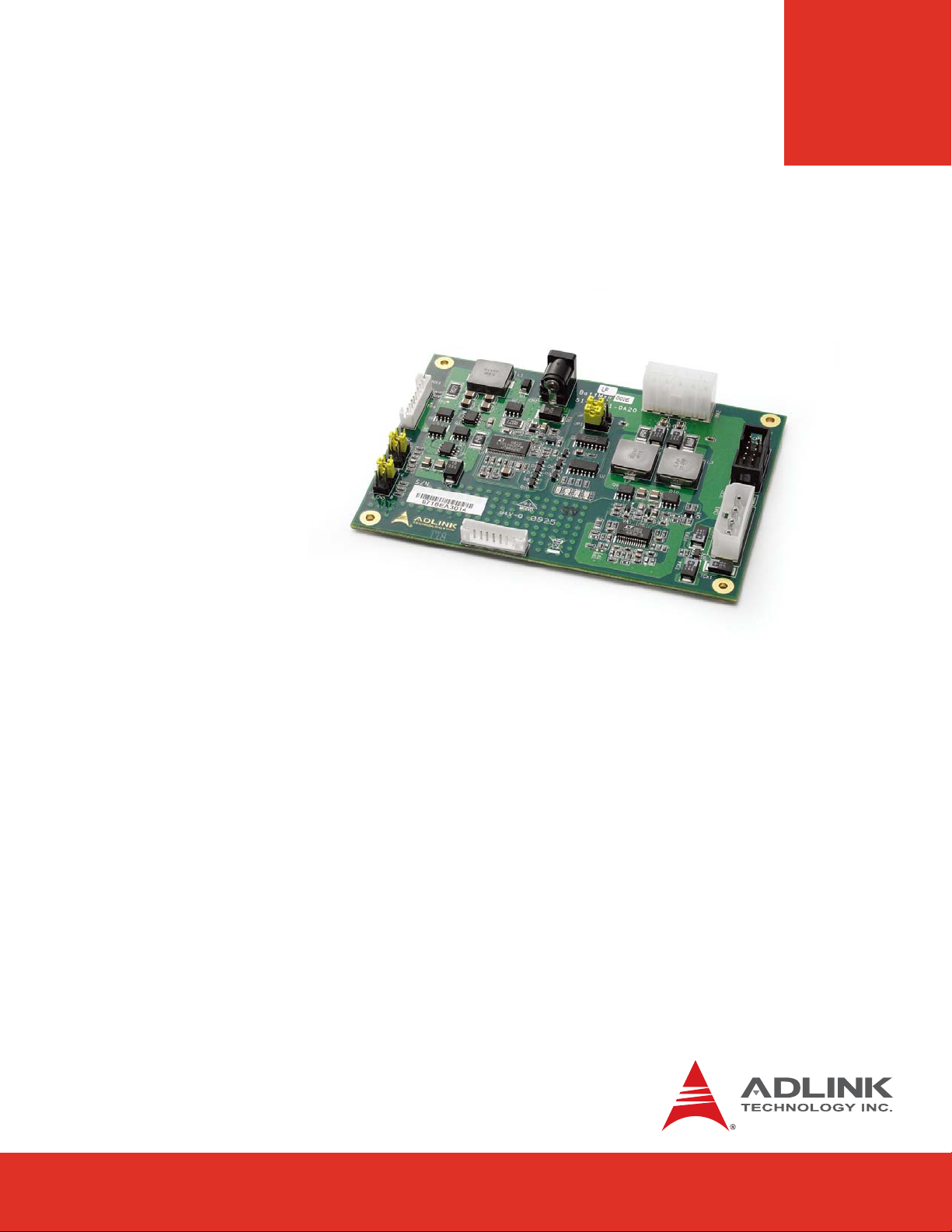
ADLINK’s BattMan (Battery Management) module is a Smart Battery Management System
that supports two Smart Batteries and provides ATX power for a mobile embedded system.
The BattMan Smart Battery Reference System is a proof-of-concept battery power
subsystem that allows for quick development and integration of battery power into a COM
Express system in the following ways:
f To emulate the battery power subsystem functionality of your prototype system during
the design phase
f As a ready-made battery power subsystem for your customized system
f As a reference design to integrate a battery power subsystem into your custom-designed
carrier (schematic provided)
The BattMan Smart Battery Reference System is compliant with the Smart Battery Manager
Specification and uses the System Management Bus (SMBus) for communications between
the battery power subsystem, Smart Batteries and host system (COM module and carrier).
The BattMan module is ACPI compliant and provides complete battery management under a
supporting operating system. ADLINK's COM Express modules feature a BIOS that fully
supports all Smart Battery communications using existing interfaces defined in the COM
Express specification and are fully compatible with the BattMan module.
The BattMan module delivers power output to a standard ATX 20-pin connector and provides
an Auxiliary Power 4-pin Molex connector for storage devices. Power input is from a 19V AC/
DC adapter. When not connected to a host system, the BattMan module can function as a
stand-alone battery charger.
Power to
Carrier Board
SMBus
to Host System
Auxilary Power
Battery 1
19V
DC
Battery 2
BattMan User’s Guide Page 11
Page 11Express-IA533 User’s Manual Page 11Express-IA533 User’s ManualExpress-CB User’s Manual Page 11
Page 12

2 Electrical Specification
The Battman module is a single or dual Smart Battery Manager. The module supports a
standard 2.5 mm DC Input Jack for connection of a standard 19V AC/DC power adapter. The
battery charger output voltage is configurable to adapt it to battery packs consisting of 2, 3,
4 or 5 Li-ion battery cells*. The module can work in either notebook mode (ACPI) or as
stand-alone battery charger.
* Battery packs with 2 or 3 cells cannot provide 12V output and will not support the
requirements of COM Express systems.
2.1 Input Power
AC/DC Adapter Input Battery**
Voltage 19 V 14.8 V nominal
Max. Current 4.74 A 4.2 A (2.5 A nominal)
Power 90 W n.a.
**The battery packs provided with the BattMan module have 4 Li-ion cells in series, 2 cells
in parallel
2.2 Output Power
12 V*** 5 Vsb 5 V (Aux. Power) Charger
Voltage 12.2 5.1 5.1 n.a.
Current (max.) 7.2 A 4.5 A 2 A 4.1 A
Spike current <10 sec 9 A 9 A 4.5 A n.a.
Power 87.8 W 22.9 W 10.2 W 50 W
*** 12V output requires battery packs with 4 or 5 cells.
2.3 Functional Characteristics
f Dual Charging - charges two Smart Batteries simultaneously to reduce charging time
f Simultaneous Discharge - simultaneous dual discharge increases battery operating
time by reducing internal battery losses due to high discharge rates
Page 12
BattMan User’s Guide
Page 13

3 Functional Block Diagram
The BattMan module provides 12V and 5Vsb to the COM Express Carrier Board and 12V and
5V to the Auxiliary Power connector to support a storage device.
The BattMan module communicates with the COM Express host system via the Host SMBus
interface. The BattMan module acts as a slave and the COM Express module sends
commands to the BattMan module to get information. The three SMBus signals SMB_CLK,
SMB_DAT and SMB_ALERT# correspond to pins B13, B14 and B15 on the AB connector of
the COM Express module. A Local SMBus is used for communciations between the BattMan
module and Smart Batteries.
COM Express Carrier
COM
Express
Module
with
Smart Battery
support
in BIOS
B15
B14
B13
Smart
Battery 1
VBAT1 +
VBAT1 -
Thermistor 1
Local SMB_CLK
Local SMB_DAT
Smart
Battery
VBAT1 +
VBAT1 -
Thermistor 1
Local SMB_CLK
Local SMB_DAT
BattMan
Smart Battery
Management
110/220VAC
12V
GND
5Vsb
Module
Adapter
AC
Host SMB_CLK
Host SMB_DAT
Host SMB_Alert
19VDC
HDD
BattMan User’s Guide Page 13
Page 13Express-IA533 User’s Manual Page 13Express-IA533 User’s ManualExpress-CB User’s Manual Page 13
Page 14

4 Mechanical Dimensions
84.71
14.93
121.02
dimensions in mm
Page 14
BattMan User’s Guide
Page 15

5 Component Locations
CNX3
CN2
CN5
CN1
BattMan
51-79201-
JP2
JP1
LED4
CNX4
CNX2
CN6
LED1
LED2
LED3
CNX1
Connector Function
CN1 19V AC/DC Power Adapter Input
CN2 Low Battery Voltage Trip Threshold Jumper
CN5 Maximum Charge Voltage Jumper
CN6 Host Control/Monitor Connector
CNX1 Auxiliary Output Power Connector
CNX2 ATX Output Power to Host System Connector
CNX3 Battery 1 Connector
CNX4 Battery 2 Connector
JP1 Operating Mode Jumper
JP2 Charger Enable/Disable Jumper
BattMan User’s Guide Page 15
Page 15Express-IA533 User’s Manual Page 15Express-IA533 User’s ManualExpress-CB User’s Manual Page 15
Page 16
6 Module Configuration
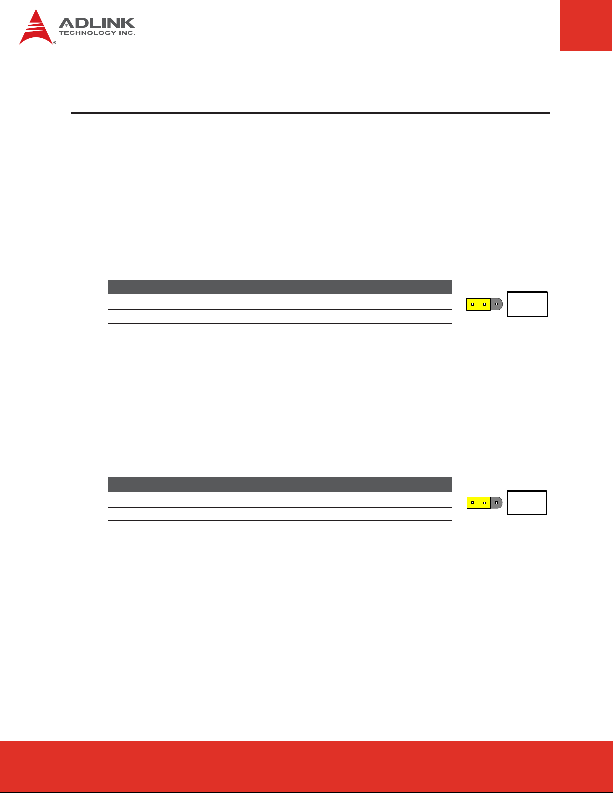
6.1 Operating Mode
The BattMan module supports two operating modes that are configurable by jumper setting:
f Battery Management Mode - connects with the COM Express host system via the Host
SMBus interface to function as a Smart Battery Management System
f Stand-alone Charger Mode - acts as a stand-alone charger for two Smart Batteries
The operating mode is set using jumper JP1.
JP1 Mode
1-2 Battery Management Mode (default)
2-3 Stand-alone Charger Mode
6.2 Charger Enable/Disable
The BattMan module charger function can be enabled or disabled by jumper setting. When
the charger is enabled and the 19V AC/DC power adapter is connected, Smart Batteries
connected to the module will be charged automatically according to the battery status. When
the charger is disabled, Smart Batteries connected to the module will not be charged.
JP1
The charger function is set using jumper JP2.
JP2 Mode
1-2 Enabled (automatic charging) (default)
2-3 Disabled (charger OFF)
JP2
Page 16
BattMan User’s Guide
Page 17
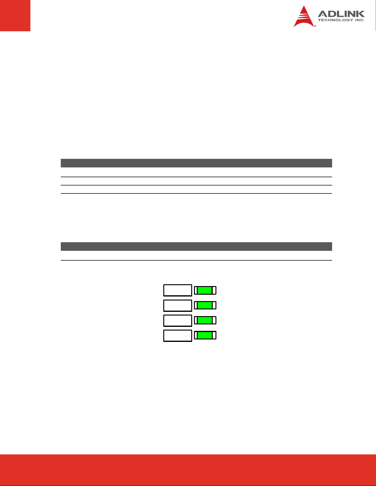
6.3 Indicator LEDs
LED4
LED1
LED2
LED3
There are four LEDs to indicate the Operating Mode and Charger Status of the BattMan
module. The functions of LED1~4 are dependent on the settings of JP1 and JP2.
When in Battery Management Mode (JP1 pins 1-2 shorted), LED1/LED2 are connected to the
Host SMBus clock and data signals and are ON to indicate that the BattMan module is
actively communicating with the Host System. LED3 is connected to the SMB_ALERT signal
and will light briefly during system power up but will remain OFF during normal operation.
When in Stand-alone Charger Mode (JP1 pins 2-3 shorted), LED1 is OFF and LED2/LED3
indicate the charging status of Battery2/Battery1 respectively (ON if charging).
LED JP1 (1-2) Battery Management Mode JP1 (2-3) Stand-alone Charger Mode
1 (ON) SMB_CLK Active OFF
2 (ON) SMB_DA T Active ON if Battery2 charging
3 SMB_ALER T Active ON if Battery1 charging
When the charger is enabled (JP2 pins 1-2 shorted) and the 19V AC/DC power adapter is
connected, LED4 is ON. When the charger is disabled (JP2 pins 2-3 shorted) or the 19V AC/
DC power adapter is not connected, LED4 is OFF.
LED JP2 (1-2) Charger Enabled JP2 (2-3) Charger Disabled
4 ON (charger enabled & 19VDC present) OFF (charger disabled or no 19VDC)
BattMan User’s Guide Page 17
Page 17Express-IA533 User’s Manual Page 17Express-IA533 User’s ManualExpress-CB User’s Manual Page 17
Page 18
6.4 Battery Settings
The BattMan module has been designed to provide power to COM Express systems using
battery packs having 2, 3, 4 or 5 Li-ion cells in series. There are two jumper settings that
must be set according to the number of cells in series in the battery pack:
f Maximum Charge Voltage - protects the Smart Battery from charging with excessive
voltage
f Low Battery Voltage Trip Threshold - protects the battery from excessive power drain
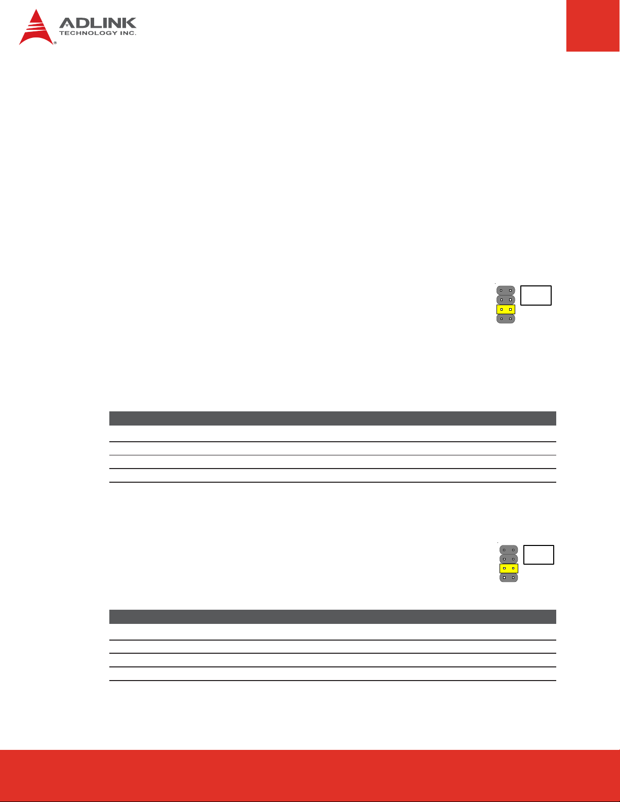
Maximum Charge Voltage (CN5)
The Maximum Charge Voltage setting is a hardware limitation on the
charging voltage supplied to the Smart Battery. The CN5 jumper setting
determines one of four voltage limits that are applied to the charger voltage
output value. These limits provide a measure of safety with a hardware
restriction on charging voltage, which cannot be overridden by software. This voltage sets
the limit that will be applied to the battery as reported by battery. Since the battery internal
voltage monitor point is the actual cell voltage, you may see higher voltages (up to 512mV
higher) at the external charger terminals due to the voltage servo loop action.
CN5 Max Charge Voltage Li-ion Cells per Battery
1-2 8.2 V 2
3-4 12.6 V 3
5-6 16.8 V (default) 4
7-8 21 V 5
Low Battery Voltage Trip Threshold (CN2)
This jumper provides a user selectable voltage trip threshold to protect a
Smart Battery from over discharging and effectively damaging the battery. The
voltage trip threshold setting depends on the Smart Battery output voltage
which in turn depends on the number of cells in series in the battery pack.
CN5
CN2
Page 18
CN2 Max Charge Voltage Li-ion Cells per Battery
1-2 5.3 V 2
3-4 7.9 V 3
5-6 11.4 V (default) 4
7-8 14.5 V 5
BattMan User’s Guide
Page 19

7 Connector Pin Assignments
7.1 ATX Output Power to Host System Connector (CNX2)
12V and 5Vsb supply to COM Express
host system
+5 V
+5 V
+12 V
+12 V
+12 V
SB
SB
6
7
8
9
10
7.2 Auxiliary Output Power Connector (CNX1)
Power supply to peripheral devices
such as harddisks
1
Ground
2
3
4
5
1
2
3
4
Ground
Ground
Ground
Ground
+5 V
Ground
Ground
+12 V
7.3 Host Control/Monitor Connector (CN6)
All signals to and from the host system to
control and monitor the BattMan module
Pin Signal Pin Signal
1 Host SMB_CLK 2 Host SMB_DAT
3 PWRBTN 4 BATLOW
5 PS_ON 6 +3.3V
7 +12V 8 +5V
9 SMB_ALERT 10 NC
BattMan User’s Guide Page 19
1
3
5
7
9
2
4
6
8
10
Page 19Express-IA533 User’s Manual Page 19Express-IA533 User’s ManualExpress-CB User’s Manual Page 19
Page 20
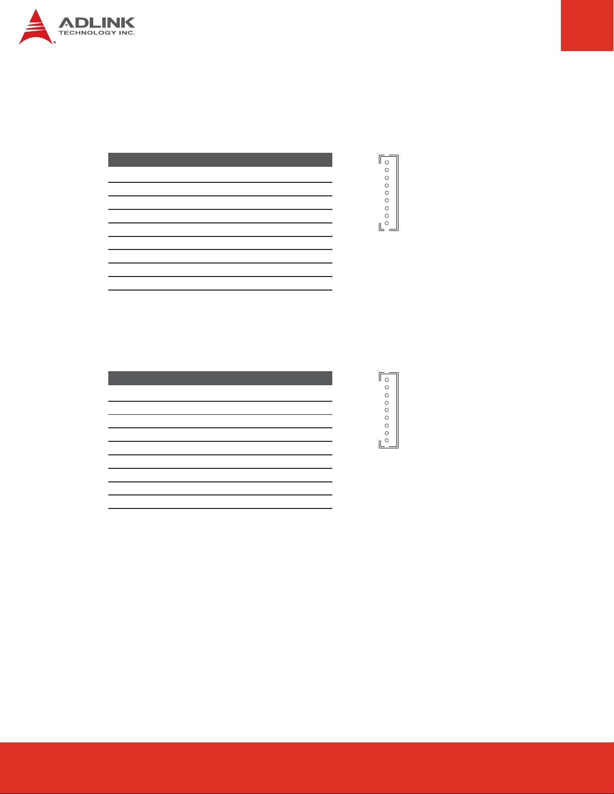
7.4 Battery 1 Connector (CNX3)
Interface between Battman and Smart Battery 1
Pin Description
1 Battery Power I/O
2 Battery Power I/O
3 Battery Power I/O
4 Local SMB_CLK
5 Local SMB_DAT
6 Thermistor Force/Sense Connection
7 Ground
8 Ground
9 Ground
7.5 Battery 2 Connector (CNX4)
Interface between Battman and Smart Battery 2
Pin Description
1 Battery Power I/O
2 Battery Power I/O
3 Battery Power I/O
4 Local SMB_CLK
5 Local SMB_DAT
6 Thermistor Force/Sense Connection
7 Ground
8 Ground
9 Ground
1
2
3
4
5
6
7
8
9
1
2
3
4
5
6
7
8
9
Page 20
BattMan User’s Guide
Page 21
8 Getting Started
This chapter describes how to connect the BattMan Smart Battery Reference System to
power a COM Express system and access the battery power subsystem information under
Windows OS.
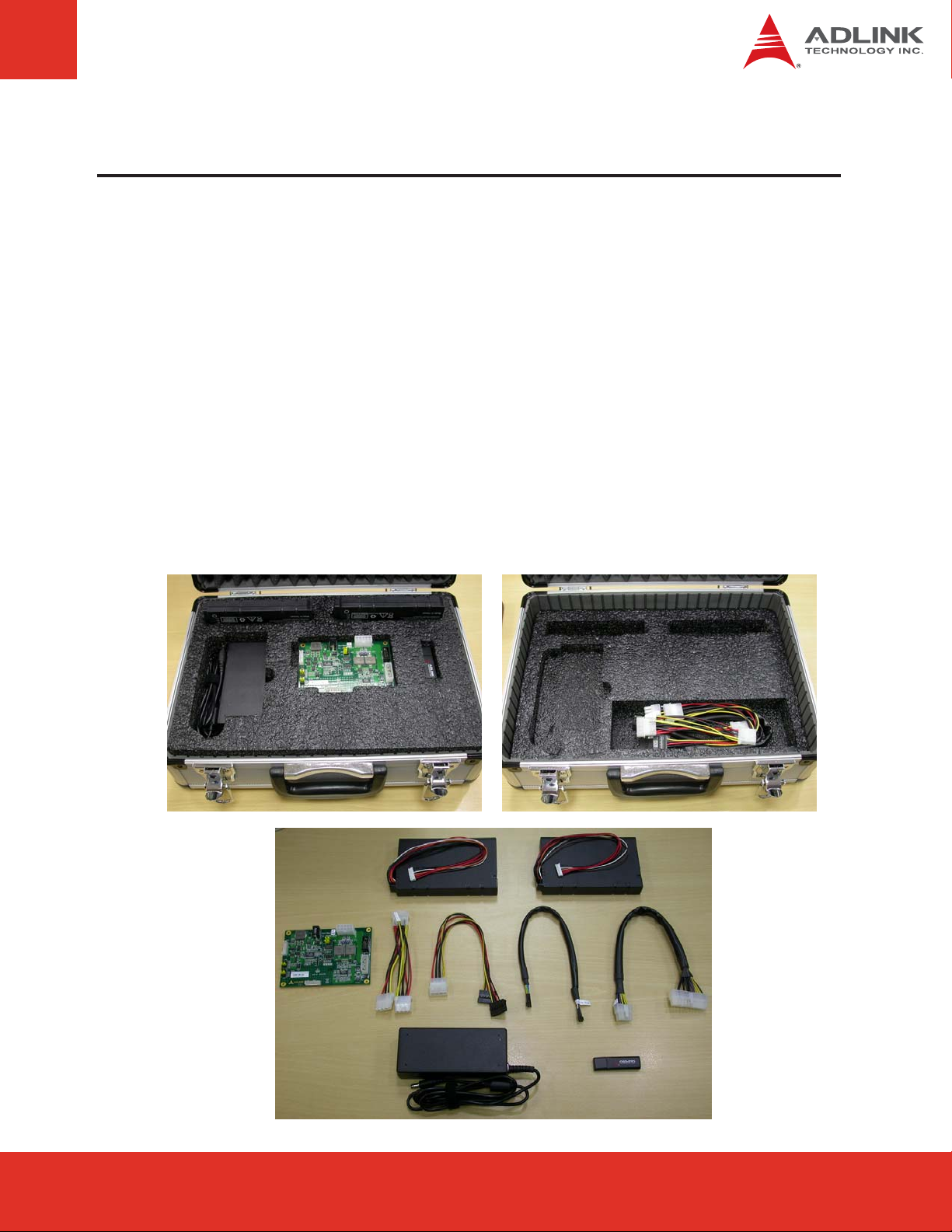
8.1 Unpacking the Contents
The BattMan Smart Battery Reference System contains the following:
f BattMan module
f Two Smart Batteries
f AC adapter
f Cables
f USB drive with manual and schematics
BattMan User’s Guide Page 21
Page 21Express-IA533 User’s Manual Page 21Express-IA533 User’s ManualExpress-CB User’s Manual Page 21
Page 22
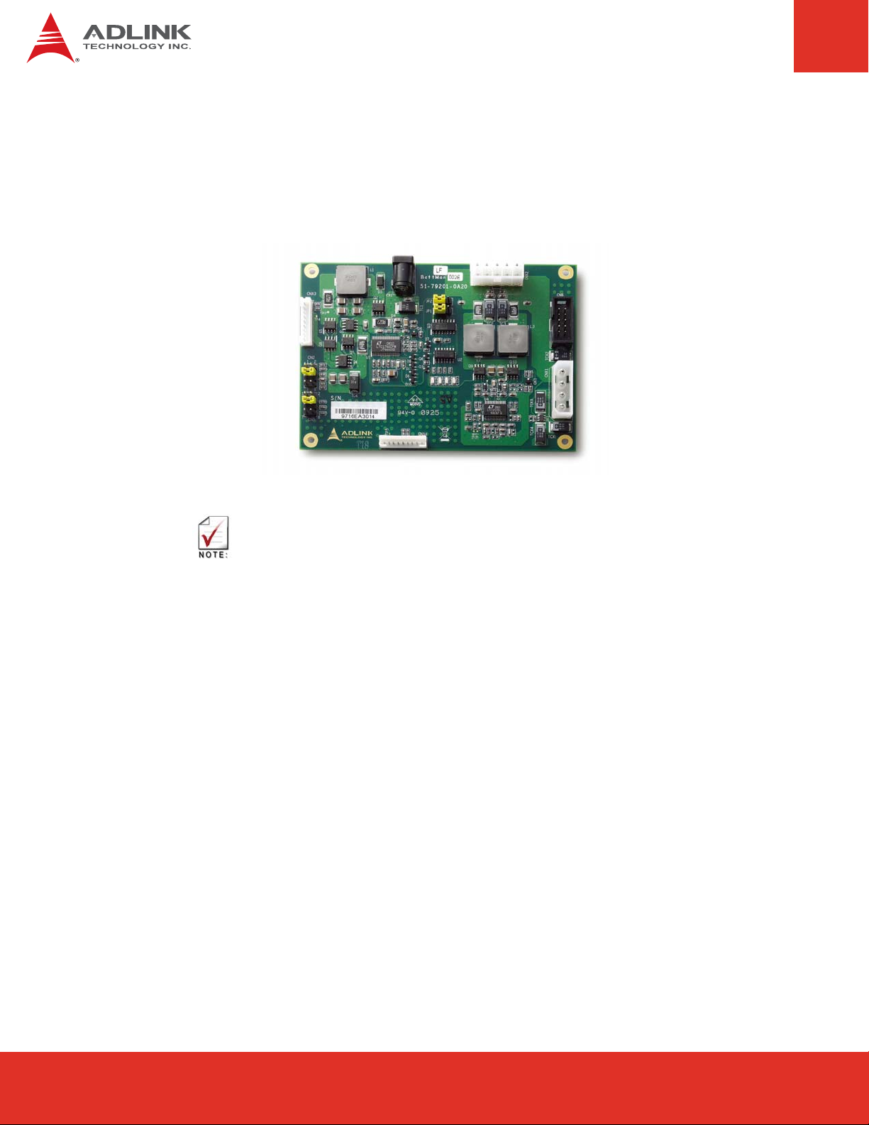
8.2 Cable Connections
The BattMan module connectors are shown in the diagram below.
19V
DC
Battery 1
Battery 2
Be sure to set JP1 and JP2 to the correct settings for your battery packs before connecting
the AC adapter to the BattMan module. See Section 6.4 Battery Settings.
Power to
Carrier Board
SMBus
to Host System
Auxilary Power
1. Connect the ATX Power output of the BattMan module (CNX2) to the ATX power input of
the COM carrier board using the 10-pin to 24-pin ATX cable provided.
2. Connect the SMBus header of the BattMan module (CN6) to the Smart Battery
Management connector on the carrier board.
3. If required, connect the Auxiliary Power output of the BattMan module (CNX1) to the
storage device using the 4-pin Molex and SATA power adapter cables provided.
4. Connect the Smart Batteries to the BattMan module.
5. Connect the DC output of the AC adapter to the BattMan module and the AC input to a
wall power outlet.
Page 22
BattMan User’s Guide
Page 23

The figure below shows a BattMan Smart Battery Reference System connected to an
Express-BASE carrier board with COM Express module and SATA hard drive.
AC
Adapter
ATX
Power
SMBus
Aux. Power
Battery 1 Battery 2
BattMan User’s Guide Page 23
Page 23Express-IA533 User’s Manual Page 23Express-IA533 User’s ManualExpress-CB User’s Manual Page 23
Page 24

8.3 Windows OS Interface
Device Presence
ADLINK's system BIOS fully supports the BattMan Smart Battery Reference System and
reports the presence of a Smart Battery device to the OS. In Windows, the battery power
subsystem information is listed in the Device Manager under the "Batteries" category. The
system BIOS will check the current system configuration and then report back to the OS.
There are three possibilities for the battery report information.
No battery power subsystem present
The system BIOS checks for the presence of a charger, selector or system manager. If there
is no device attached, it will only report the presence of an AC adapter to the OS.
BattMan module present
If the BattMan module is present in the system, the system BIOS will report an AC adapter
and two battery devices to the OS.
Page 24
BattMan User’s Guide
Page 25
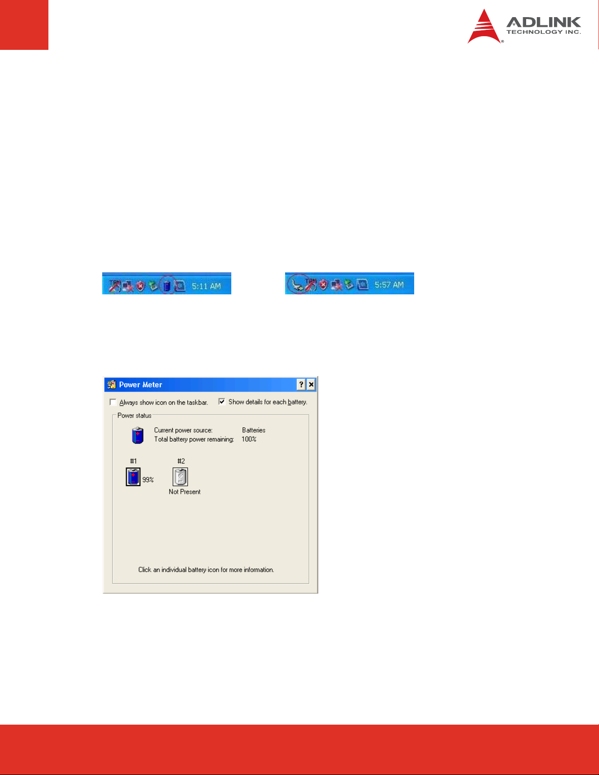
Battery State Notification
The system BIOS is notified of the state of the battery power subsystem (AC power or battery
mode) when it receives an SMBALERT# as a SCI event. An alert may be sent to update the
charging state, remaining battery capacity, or presence of an AC adapter. The OS can also
query the system BIOS to update the battery power information. Placing the cursor over the
battery state icon will cause the OS to update the battery power information.
When an AC adapter is inserted or removed, the battery state icon in the taskbar will change
to indicate the current state. To display the battery state icon in the taskbar, enable the
option "Always show icon on the taskbar" from the "Advanced" tab of "Power Options
Properties".
Battery Information
To view detailed battery status information, double-click on the battery or AC adapter icon.
BattMan User’s Guide Page 25
Page 25Express-IA533 User’s Manual Page 25Express-IA533 User’s ManualExpress-CB User’s Manual Page 25
Page 26

9 References
Following specifications are used for reference to develop the smart battery management
support for ADLINK Computer-on-Module (COM) products.
f Advanced Configuration and Power Interface Specification, Revision 3.0.
f Smart Battery Charger Specification, Revision 1.1.
f Smart Battery Data Specification, Revision 1.1
f Smart Battery Selector Specification, Revision 1.1.
f Smart Battery System Manager Specification, Revision 1.0 Release Candidate b.
f System Management Bus Specification: Revision 1.1, SBS Implementers Forum
f I2C-Bus and How to Use it: V1.0, Philips Semiconductor.
Page 26
BattMan User’s Guide
Page 27

This page intentionally left blank.
BattMan User’s Guide Page 27
Page 27Express-IA533 User’s Manual Page 27Express-IA533 User’s ManualExpress-CB User’s Manual Page 27
Page 28

 Loading...