

Page 1
AMP-204C / AMP-208C
Advanced DSP Pulse Motion Controller
for 4/8 Axis
User Manual
Manual Rev.: 2.00
Revision Date: July 25, 2014
Part No: 50-15089-1000
Advance Technologies; Automate the World.
Page 2

Revision History
Revision Release Date Description of Change (s)
2.00 2014-07-25 Initial release
ii
Page 3

AMP-204C / AMP-208C
Preface
Copyright 2014 ADLINK Technology, Inc.
This document contains proprietary information protected by
copyright. All rights are reserved. No part of this manual may be
reproduced by any mechanical, electronic, or other means in any
form without prior written permission of the manufacturer.
Disclaimer
The information in this document is subject to change without prior
notice in order to improve reliability, design, and function and does
not represent a commitment on the part of the manufacturer.
Under no circumstances will ADLINK be held liable to this
document.
In no event will the manufacturer be liable for direct, indirect,
special, incidental, or consequential damages arising out of the
use or inability to use the product or documentation, even if
advised of the possibility of such damages.
Environmental Responsibility
ADLINK is committed to fulfill its social responsibility to global
environmental preservation through compliance with the
European Union's Restriction of Hazardous Substances (RoHS)
directive and Waste Electrical and Electronic Equipment (WEEE)
directive. Environmental protection is a top priority for ADLINK.
We have enforced measures to ensure that our products,
manufacturing processes, components, and raw materials have as
little impact on the environment as possible. When products are at
their end of life, our customers are encouraged to dispose of them
in accordance with the product disposal and/or recovery programs
prescribed by their nation or company.
Trademarks
Product names mentioned herein are used for identification
purposes only and may be trademarks and/or registered
trademarks of their respective companies.
Preface iii
Page 4

Conventions
Take note of the following conventions used throughout this
reference to make sure that users perform certain tasks and
instructions properly.
Additional information, aids, and tips that help users perform
tasks.
NOTE
NOTE
Information to prevent minor physical injury, component
damage, data loss, and/or program corruption when trying to
CAUTION
WARNING
complete a task.
Information to prevent serious physical injury, component
damage, data loss, and/or program corruption when trying to
complete a specific task.
iv Preface
Page 5

AMP-204C / AMP-208C
Contents
Revision History...................................................................... ii
Preface.................................................................................... iii
List of Figures........................................................................ ix
List of Tables........................................................................ xiii
1 Introduction ........................................................................ 1
1.1 Product Specifications ......................................................... 4
1.2 Software Support ................................................................. 8
Software Support Library ................................................ 8
MotionCreatorPro 2 ........................................................ 8
1.3 Terminal Board .................................................................... 8
2 Getting Start with The Installation.................................... 9
2.1 Package Contents ............................................................... 9
2.2 AMP-204C / AMP-208C Exterior Profile Diagram ............. 10
2.3 Hardware Installation ......................................................... 12
Hardware Configuration ................................................ 12
Installation Procedures ................................................. 12
Troubleshooting ............................................................ 13
2.4 Software Installation Procedure......................................... 14
2.5 Definitions to Key Connector Signal .................................. 16
AMP-204C:P1 Connector ............................................. 16
AMP-208C:P1-A/B Connector ...................................... 18
AMP-204C/208C:P2 Connector .................................... 21
2.6 DIP Switch ......................................................................... 23
SW2: Card ID Switch .................................................... 23
2.7 IDE 44p – DSUB 37p Bus.................................................. 24
2.8 Exclusive Board - DIN-825-GP4 ........................................ 25
Contents v
Page 6

Definitions to Connector ............................................... 26
P1 Connector: For Connecting to PCI-8254 / PCI-8258 /
AMP-204C / AMP-208C ................................................ 28
S1, S2: EDO/ALM_RST Selection Switch .................... 37
3 Signal Connection ............................................................ 39
3.1 Pulse Command ................................................................ 40
3.2 Encoder Input, EA & EB & EZ............................................ 43
3.3 Emergency Stop Input ....................................................... 45
3.4 PEL/MEL Input................................................................... 46
3.5 ORG Input.......................................................................... 48
3.6 INP Input ............................................................................ 49
3.7 ALM Input .......................................................................... 50
3.8 SVON Output ..................................................................... 51
3.9 Comapre & Trigger Output:................................................ 52
3.10 Digital Output/Input ............................................................ 54
4 Motion Control Theory ..................................................... 59
4.1 Motion Control Mode and Interface Overview.................... 60
4.1.1 Motion Control Interface ........................................... 60
4.1.2 Control Cycle ............................................................ 66
4.2 Motion Control Operations ................................................. 68
4.2.1 Coordinated System ................................................. 68
4.2.2 Unit Factor ................................................................ 69
4.2.3 Acc/Deceleration Profile ........................................... 72
4.3 Home Move........................................................................ 78
4.3.1 OGR Signal Homing - Home Mode = 0 .................... 81
4.3.2 EL Signal Homing - Home Mode 1 ........................... 88
4.3.3 Single EZ Signal Homing.......................................... 91
4.4 Velocity Move..................................................................... 94
4.5 Jog Move ........................................................................... 97
4.6 Point-to-Point Move ......................................................... 101
4.6.1 Point-to-Point Move ................................................ 101
vi Contents
Page 7

AMP-204C / AMP-208C
4.6.2 Synchronous Start .................................................. 102
4.6.3 On The Fly Change ................................................ 103
4.6.4 Continuous PTP Move............................................ 103
4.7 Interpolation ..................................................................... 106
4.7.1 Linear Interpolation................................................. 106
4.7.2 Arc Interpolation ..................................................... 108
4.7.3 Continuous Interpolation......................................... 116
4.8 Motion Status Monitoring ................................................. 122
4.8.1 Motion Status.......................................................... 123
4.9 Application Functions....................................................... 132
4.9.1 Electronic Gearing .................................................. 132
4.9.2 High Speed Position Compare Trigger................... 134
4.9.3 PWM Control (Laser Control) (VAO Table Control)140
4.9.4 Motion Control and I/O Sampling Function............. 148
4.9.5 Simultaneous Movement ........................................ 153
4.9.6 Point Table Movement............................................ 156
4.10 Safety Protection ............................................................. 161
4.10.1 Hardware Protection ............................................... 161
4.10.2 Software Protection ................................................ 164
4.11 Host Interrupt ................................................................... 168
Important Safety Instructions............................................ 176
Getting Service.................................................................... 178
Contents vii
Page 8

viii Contents
Page 9

AMP-204C / AMP-208C
List of Figures
Figure 1-1: AMP-204C/208Csystem block diagram...................... 2
Figure 1-2: System installation flow chart ..................................... 3
Figure 2-1: AMP-204C exterior profile diagram .......................... 10
Figure 2-2: AMP-208C exterior profile diagram .......................... 11
Figure 2-3: Exterior of DIN-825-GP4 .......................................... 25
Figure 2-4: Exterior of DIN-825-GP4 .......................................... 26
Figure 3-1: Line Driver type pulse control command signal
connection example41
Figure 3-2: Open-Collector type pulse control command signal
connection example42
Figure 3-3: Line driver type encoder input signal connection example
44
Figure 3-4: Emergency stop signal connection example ............ 45
Figure 3-5: Mechanical limit switch signal connection example.. 47
Figure 3-6: Original position switch signal connection example . 48
Figure 3-7: In-position signal connection example...................... 49
Figure 3-8: Servo alarm signal connection example................... 50
Figure 3-9: Servo-on signal connection example........................ 51
Figure 3-10: Line Driver type compare trigger signal connection
example52
Figure 3-11: Open-Collector type compare trigger signal connection
example53
Figure 3-12: General purpose digital I/O signal connection example
55
Figure 3-13: General purpose digital I/O signal connection example
58
Figure 4-1: Format of pulse signal .............................................. 61
Figure 4-2: Control cycle............................................................. 67
Figure 4-3: Controller coordinates system block......................... 68
Figure 4-4: Relation of trapezoidal speed profile's
speed/acceleration/jerk VS time72
Figure 4-5: Maximum speed by auto-planning............................ 73
Figure 4-6: Relation of S-curve speed profile's
speed/acceleration/jerk VS time74
Figure 4-7: Auto-planning the maximum velocity........................ 76
Figure 4-8: Home mode 0 (Case: ORG) .................................... 82
Figure 4-9: Home mode 0 (Case: ORG) .................................... 84
Figure 4-10: Home mode 0 (Case: ORG+EZ) ............................. 85
List of Figures ix
Page 10

Figure 4-11: Home mode 0 adverse (Case: ORG+EZ)................ 86
Figure 4-12: Home mode 0 decelerate to stop (Case: ORG)....... 87
Figure 4-13: Home mode 1 (Case: EL) ........................................ 88
Figure 4-14: Home mode 1 (Case: EL+EZ) ................................. 90
Figure 4-15: Home mode 2 (Case: EZ)........................................ 92
Figure 4-16: Home mode 2 adverse (Case: EZ) .......................... 93
Figure 4-17: Relation between V-T chart of JOG movement and
JOG-ON signal97
Figure 4-18: Jog step mode .......................................................... 98
Figure 4-19: T-curve V-T chart.................................................... 101
Figure 4-20: Dynamically change position and velocity .............. 103
Figure 4-21: Continuous three position V-T chart ....................... 104
Figure 4-22: Continuous three position V-T chart
(auto speed connection (1)104
Figure 4-23: Continuous three position V-T chart
(auto speed connection (2)104
Figure 4-24: Continuous three position V-T chart
(auto speed connection (3)105
Figure 4-25: Continuous three position V-T chart
(auto speed connection (4)105
Figure 4-26: Two-dimension straight line interpolation ............... 107
Figure 4-27: Three-dimension arc interpolation (method 1)........ 109
Figure 4-28: Defining spatial normal vector ................................ 110
Figure 4-29: Determining arc direction in space ......................... 110
Figure 4-30: Three dimension arc interpolation (method 2)........ 111
Figure 4-31: Three dimension arc interpolation example............ 112
Figure 4-32: Three dimension spiral interpolation (method 1) .... 113
Figure 4-33: Three-dimension spiral interpolation (method 2) .... 114
Figure 4-34: Illustration on continuous interplotation (Buffer)
movement116
Figure 4-35: Velocity blending (method 1) .................................. 117
Figure 4-36: Velocity blending (method 2) .................................. 118
Figure 4-37: Velocity blending (method 3) .................................. 118
Figure 4-38: Velocity blending (method 4) .................................. 119
Figure 4-39: Velocity blending (method 5) .................................. 119
Figure 4-40: Velocity blending (method 6) .................................. 120
Figure 4-41: Velocity blending (method 7) .................................. 120
Figure 4-42: Continuous interpolation examples......................... 121
Figure 4-43: Motion status monitoring process ........................... 122
Figure 4-44: Relation of different motion signals VS motions ..... 125
xList of Figures
Page 11

AMP-204C / AMP-208C
Figure 4-45: Relation of motion done (MDN) signal VS motion .. 126
Figure 4-46: Relation of motion done (MDN), In-homing (HMV) signals
VS motion127
Figure 4-47: Relation of WAIT signals VS motion....................... 128
Figure 4-48: Relation of JOG and motion done(MDN) signals VS
motion129
Figure 4-49: Relation of ASTP VS motion .................................. 129
Figure 4-50: Relation of blending (BLD) signal VS motion ......... 130
Figure 4-51: Relation between pre- and post-distance event signals
and movement131
Figure 4-52: Adjust electronic gear's auto engagement speed... 133
Figure 4-53: Compare trigger block diagram .............................. 135
Figure 4-54: Linear compare trigger example ............................. 137
Figure 4-55: Table compare trigger example .............................. 138
Figure 4-56: Table compare trigger block diagram ..................... 139
Figure 4-57: Signal sampling structure diagram ......................... 148
Figure 4-58: Interruption flow chart ............................................. 168
List of Figures xi
Page 12

xii List of Figures
Page 13

AMP-204C / AMP-208C
List of Tables
Table 1-1: Cross-reference table of exclusive cables for pulse servo
drive8
Table 4-1: Encoder input format ..................................................... 63
Table 4-2: Encoder input format ..................................................... 63
Table 4-3: Board parameter table ................................................. 146
Table 4-4: Motion kernel signal table ............................................ 149
List of Tables xiii
Page 14

xiv List of Tables
Page 15

AMP-204C / AMP-208C
1 Introduction
The AMP-204C / AMP-208C, is a fully in-house developed
DSP-based advanced motion control card from ADLINK. It
supports 4/8 axis pulse type signal commands, provides
open-loop circuit control options, and supports position commands
for several different servo drives.
AMP-204C / AMP-208C exchanges data with operating system
through high speed PCI bus including motion control command,
feedback data, parameter, etc. Used with the ADLINK exclusive
Softmove kernel, it offers scores of move control functions
including T/S speed profile planning, point-to-point movement,
multi-dimension interpolation, and master/slave motion.
The AMP-204C / 208C, see Figure 1 below for its system functions,
uses one digital signal processor (DSP) from Texas Instrument (TI)
as its main computing unit and integrates high speed large volume
Field Programmable Gate Array (FPGA) to provide high speed
encoder output, 2/4 high speed position compare and trigger output,
move & general purposed I/O and logic control. It separates
isolation circuit into exclusive terminal board DIN-825-GP4 to
prevent the burning out of AMP-204C/208C from incorrect wiring.
Thanks to full range of flexing resistant wires from ADLINK, it
connects with market avaialble popular servo dirves easily.
Introduction 1
Page 16

SCSI 100P
PCI Bus
PCI Bus
Isolation
DSUB 37P
DIN-825-GP4
Figure 1-1: AMP-204C/208Csystem block diagram
Graphical motion control interface – MotionCreatorPro 2 is a
Windows-based motion control software development tool for
motion control and I/O status monitoring. It captures motion curves
and data at the same time for analysis. Its Setup Wizard guides
you through the hardware installation and wiring as well as
single-axis manipulation step-by-step. This saves your
development time and cost.
2Introduction
Page 17
AMP-204C / AMP-208C
The Windows Programming Libraries supports Windows coding
environment including: Visual Studio C++ 6.0, Microsoft .NET
framework based VB.NET and C++, and Borland's C++ Builder.
There are sample programs available in the installation folders.
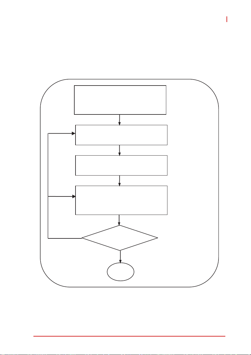
The flow chart below will guide you in using this manual as well as
help you to locate any required information effectively.
Hardware installation
Wiring and jumper setup
Set up card and adjust axis parameters
with MotionCreatorPro 2
Control axis with MotionCreatorPro 2
Develop application with APS library
No
Is the system running
successfully?
Yes
Chapter II and III
MotionCreatorPro 2
User's Manual
Chapter IV
MotionCreatorPro 2
User's Manual
APS and ADCNC
library
End
Figure 1-2: System installation flow chart
Introduction 3
Page 18

1.1 Product Specifications
Item Description
Bus information PCI Rev. 2.2, 33MHz
System
DSP
Board-to-board
interface
Motion control
I/O interface
General
purpose digital
I/O
PCI bus width 32-bit
PCI bus voltage 3.3V, 5V
PCI bus IRQ settings Assigned by PCI controller
Model TI 375MHz floating DSP
Memory (for program and
data)
Connector
Number of axes supported
Track update rate
Position / speed command
range
Acceleration / deceleration
range
Encoder input frequency 20 MHz @ 4x AB
Encoder input mode
Encoder input interface ±12 volts, TTL compatible
Motion control relevant I/O
Drive relevant I/O
General purpose I/O
DDR2 SDRAM: 64Mx16bit
Flash ROM: 16M-bit
1x SCSI-II 100P for
AMP-204C
1x Dual SCSI VHDCI 100P
AMP-208C
for
4/8 axis for AMP-204C /
AMP-208C
500us, 1ms, 2ms
(programmable)
32 bit
32 bit
CW/CCW, 1x/2x/4x AB
Phase
Plus/Minus end limitsignal
Zero-position for each axis
Servo ON
In-position signal /
Zero-Speed detection
Alarm
20/24-CH input & 20/24-CH
TTL output (optical
isolation design for
DIN-825-GP4)
4Introduction
Page 19

Motion control
function
AMP-204C / AMP-208C
Item Description
Speed Profile Planning
Trajectory Planing
Linear interpolation:
2-6 axes
Home Return
Trapezoidal Curve and
S-Curve
Jogging
Point-to-point movement
Online position/speed
change
3 axes arc interpolation
3 axes spiral interpolation
3 axes helix interpolation
User customization (see
zero-position, limit switch,
EZ signals for reference)
Introduction 5
Page 20

Industrial
application
Interrupt
Position
comparison
&
trigger output
Item Description
Each axis supports 50
points buffer memory
(BUFs)
Supports
Point table
Motion Status Monitoring
Synchronous move
Master-client axes control
Data sampling
System error diagnostics Watchdog timer
Motion status event/error
alarm/in position/
emergency stop
Pulse output interface Difference output
Trigger channel
Pulse logic
Trigger output frequency
Minimum pulse width 100ns programmable
Position comparison mode
FIFO capacity
point-to-point/line/arc and
spiral interpolation
Supports dwell function
Supports pause/resume
function
Supports DO function
Motion control relevant I/O
monitoring
Motion status monitoring
4/8 axes corresponding
AMP-204C / AMP-208C
Up to 4/8 axis (including
ganty control)
Motion speed profile/
motion status/motion
control relevant I/O
Planning in accordance
with the manual
2/4 corresponding
AMP-204C / AMP-208C
Programmable active-high
or active-low
Linear compare trigger:
1MHz
FIFO compare trigger:
255K ~ 1MHz
FIFO and linear
comparison
255 points (channel
independent)
6Introduction
Page 21

Item Description
PWM control
Maximum number of
channels
Control modes
Resolution 16 bit
Environment condition
Working
ambient
temperature
Storage
ambient
temperature
Working
ambient
humidity
0~55°C
-20~75°C
10~90%RH, without condensation
AMP-204C / AMP-208C
2/4 CH correspondence
AMP-204C / AMP-208C
● Fixed frequency,
variable duty cycle ratio
● Variable frequency, fixed
duty cycle ratio
● Variable frequency,
variable duty cycle ratio
Item
Storage
ambient
humidity
Noise
impedance
Environment
condition
Cooling
condition
Power
consumption
Introduction 7
10~90%RH, without condensation
Noise voltage 1500VPP noise frequency 25~60Hz using
noise simulator
Minimal corrosive gas, dust
Self-cooling
+3.3V @ 0.8A typical
+5V @ 0.8A typical
+/-12V @ 0.5A typical
Page 22

1.2 Software Support
1.2.1 Software Support Library
AMP-204C / AMP-208C supports Windows XP/7 32/64 bit
operating system and provides a complete function library and
DLL files for easy application development by users.
1.2.2 MotionCreatorPro 2
MotionCreatorPro 2 is a user interface exclusively developed for
ADLINK motion control products in common Windows
environment. You may easily set up card and axis parameters with
the help of MotionCreatorPro 2. Its Setup Wizard guides you
through the hardware installation and wiring as well as single-axis
manipulation in couple of minutes. MotionCreatorPro 2 not only
effectively reduces your development time but also enables you to
concurrently validate the overall mechanism and electric design
with all its single axis and interpolation motion operation pages.
1.3 Terminal Board
ADLINK's exclusive terminal board DIN-825-GP4 for
AMP-204C/208C can connect with market available servo drivers
with special cables, e.g. Mitsubishi's J3A and Yaskawa's Sigma V
series, or with third party's servo or stepper drivers by single
ended open cables. Brands with exclusive cables support are
listed below:
Pulse command:
Cable Supported brands
HSL-4XMO-DM Mitsubishi J2S series
4XMO-DM-J3 Mitsubishi J3A series
HSL-4XMO-DP Panasonic A4 and A5 series
HSL-4XMO-DY Yaskawa Sigma V series
4XMO-DA Delta A2 series
4XMO-OPEN General purpose
Table 1-1: Cross-reference table of exclusive cables for pulse servo drive
8Introduction
Page 23

AMP-204C / AMP-208C
2 Getting Start with The Installation
This chapter teaches you how to install AMP-204C / AMP-208C
hardware and software as well as its I/O wiring.
• Package Contents
• Hardware installation
• Software installation
• I/O wiring
2.1 Package Contents
In addition to this manual you shall find the following item in the
product package box:
• One AMP-204C or AMP-208C card
• IDE 44p – DSUB 37p flat cable x 1
• Product warranty card x 1
Should there be any item missed or damaged, please consult with
your dealer immediately. Please keep the product along with items
included in its package for easy replacement or repair.
Getting Start with The Installation 9
Page 24
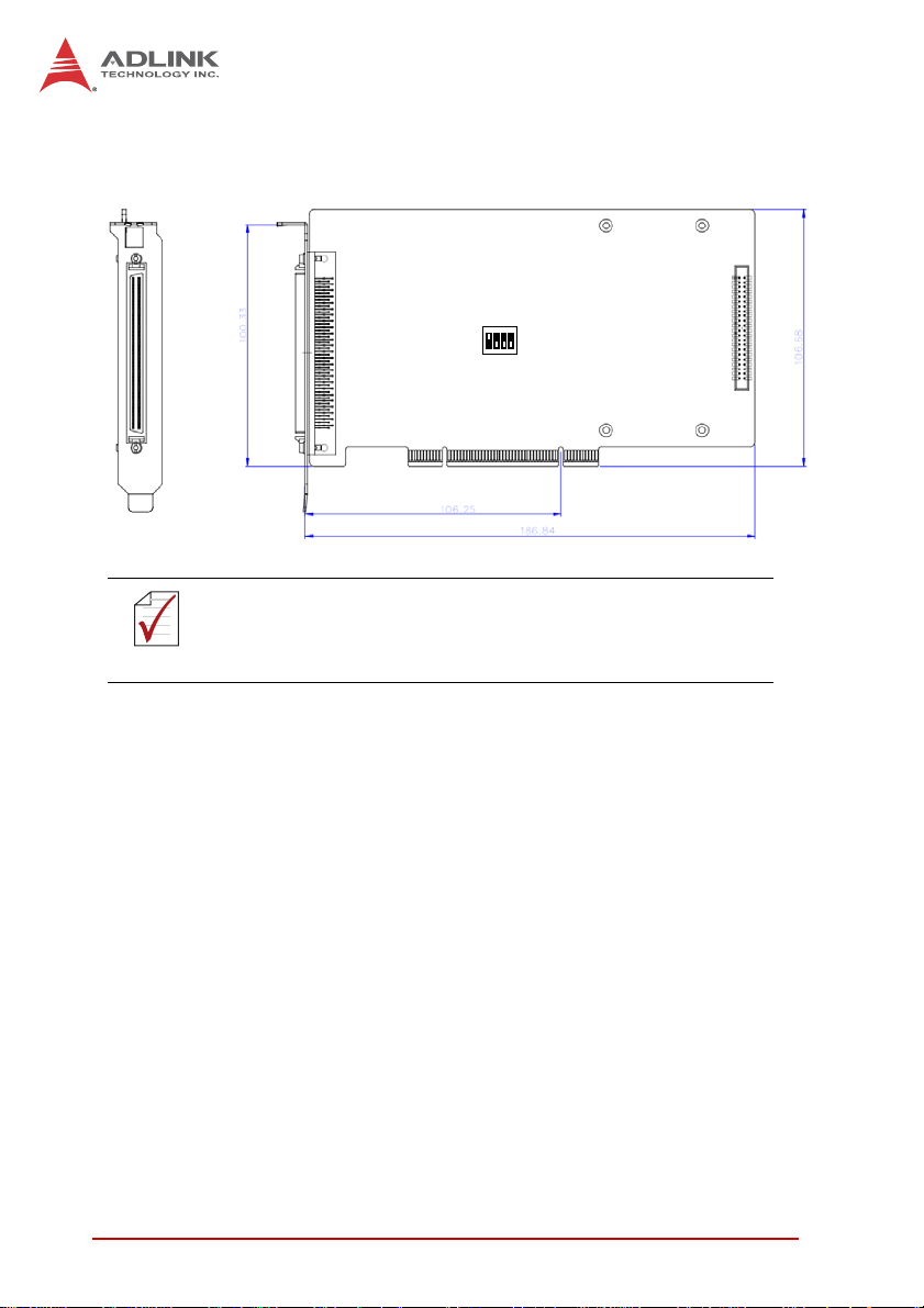
2.2 AMP-204C / AMP-208C Exterior Profile Diagram
SW2
P1
P2
Dimension in unit of millimeter (mm).
NOTE
NOTE
Figure 2-1: AMP-204C exterior profile diagram
P1: for Motion control command, Position feedback, and Servo I/O
feedback. (with SCSI 100-PINS connector)
P2:
for 16 channel digital TTL I/O. (with DSUB 37-PINS connector)
SW2:
Card ID setup (0-15)
10 Getting Start with The Installation
Page 25
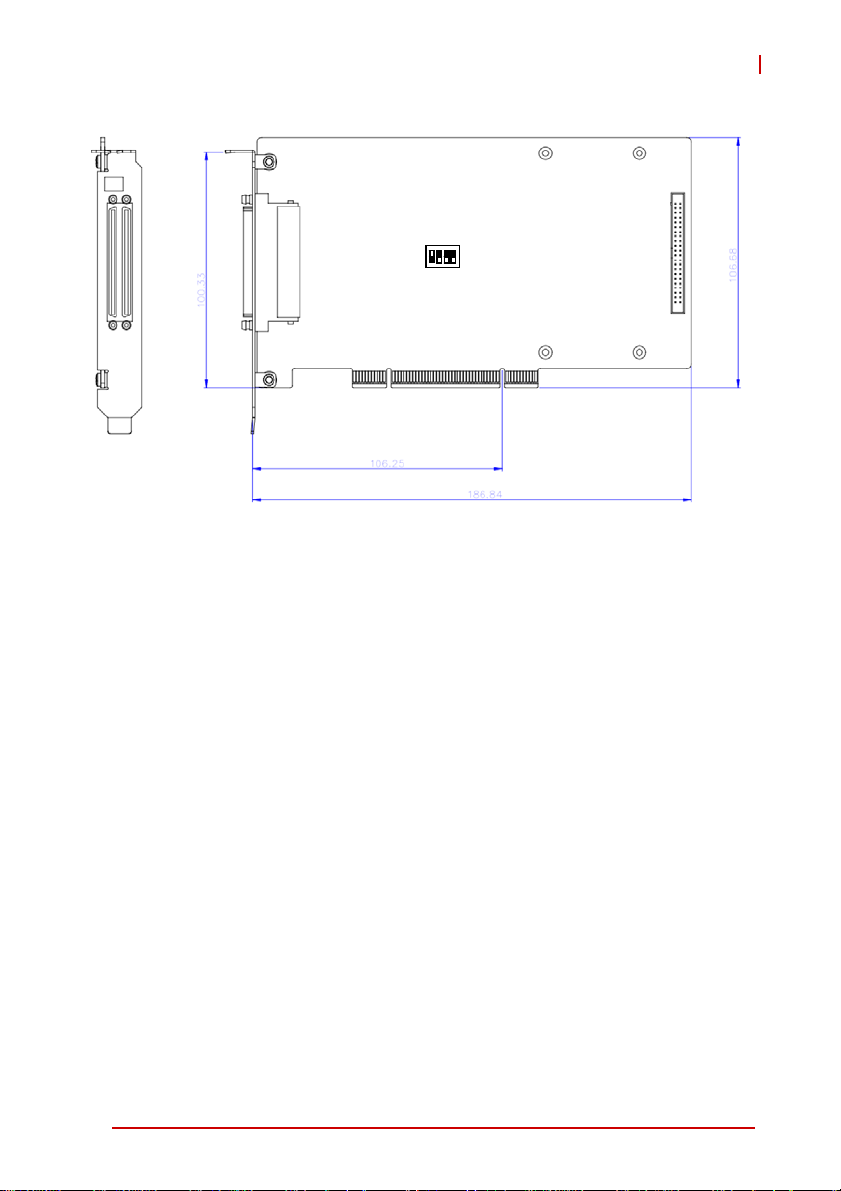
AMP-204C / AMP-208C
P1
SW2
P2
Figure 2-2: AMP-208C exterior profile diagram
P1: for Motion control command, Position feedback, and Servo I/O
feedback. (with SCSI-VHDCI 200-PINS connector)
P2:
for 16 channel digital TTL I/O. (with DSUB 37-PINS connector)
SW2: Card ID setup (0-15)
Getting Start with The Installation 11
Page 26

2.3 Hardware Installation
2.3.1 Hardware Configuration
AMP-204C/208C employs PCI Rev. 2.2 bus. System BIOS can
auto configure memory and IRQ channel.
Exclusive terminal board DIN-825-GP4 provides isolation circuit
and indicator lights for easy connections to varieties of servo drive
and stepper drive.
2.3.2 Installation Procedures
1. Please read this manual carefully and set up signal I/O in
proper mode.
2. Turn off power of your computer and all relevant terminal
boards, insert your AMP-204C/208C to any 32-bit PCI
slot in your computer. (The slot is usually in white color.)
(Please make sure you have proper ESD (Electrostatic
discharge) protection.)
3. Connect AMP-204C/208C and DIN-825-GP4 with SCSI
100p cable
4. Set up motion control relevant limit switch on
DIN-825-GP4 board, servo signal and general purpose
digital signal wiring
5. Set up servo or stepper drive connection
6. Turn on system power including computer power,
terminal board relevant powers, and 24Vdc power
7. Verify all I/O signal and servo operation correctness with
MotionCreatorPro 2
Please ground the shielding end of the power terminal to the
earth to reduce risk of electric shock and ensure product
CAUTION
CAUTION
12 Getting Start with The Installation
operation of your electric appliances.
Please disconnect the motor drive from its load before using
the card for the first time to protect your safety. Do not connect
the motor drive to any mechanical devices before the
completion of the installation and fine tuning of the control
system. Connect the system only after the board is adjusted
and the drive parameters can control the motor. Serious
damage may be resulted in otherwise.
Page 27

AMP-204C / AMP-208C
2.3.3 Troubleshooting
If the computer cannot power on normally or the motion control
system operates abnormally after system installation, please
follow steps described below for troubleshooting. If the problem
persists after you have taken steps described, please consult the
dealer where your product is purchased for technical services.
Abnormalities you
encountered
The card does not show up in
Windows Device Manager
after its driver has been
installed
MotionCreatorPro2 cannot
open after installing driver in
computer.
The without signal indicator on
MotionCreatorPro2 lights up
after the motor is connected
and the motor does not work.
When using the
MotionCreatorPro2 all the
control indicators of the drive
light correctly but the drive
warns
Value of output command
differ from the feedback value
from encoder
If motion control, the motor
moves only in one direction
rather than back and forth two
way movement
Potential causes
Please turn off your computer,
ensure the card is properly in PCI
slot and the driver is properly
installed by cheking its proper
installation in Windows Control
Panel's "Add remove programs"
Ensure .NET framework v3.5 or later
version has been installed in your
system
Please ensure a 24Vdc power is
connected to the terminal board
Please ensure correctness of the
axis parameter setup, alarm logic
(ALM) and the EMG loop
configuration
Please ensure feedback signal
(CW/CCW, 1xAB, 2xAB, 4xAB)
settings comply with that of the drive
Please ensure setting of signal pattern
(CW/CCW, OUT/DIR) comply with that
of the motor
drive
Getting Start with The Installation 13
Page 28
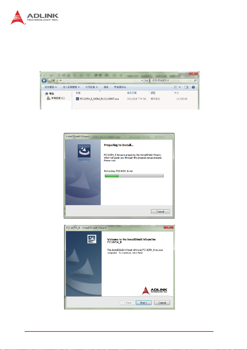
2.4 Software Installation Procedure
Windows driver installation procedure:
Step 1. Execute AMP-204C / AMP-208C WDM file and run
installation procedure automatically.
Step 2. Click "Next" as prompted to complete the installation
process.
14 Getting Start with The Installation
Page 29
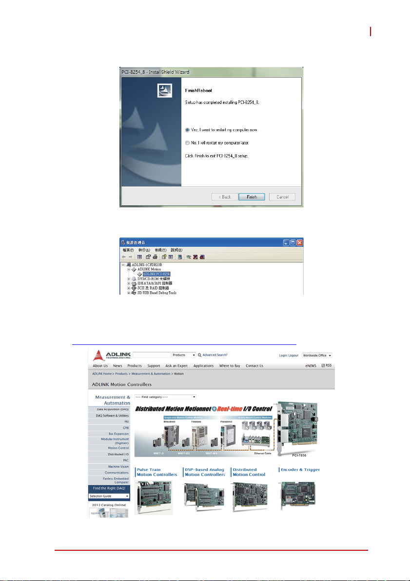
AMP-204C / AMP-208C
Step 3. Restart your computer after installation is completed.
Step 4. Ensure the Windows Device Manager identify your
AMP-204C / AMP-208C correctly.
Recommendations: Please download latest installation software
from ADLINK official website to maintain the optimum operation
environment.
(http://www.adlinktech.com/Motion-Control/index.php
)
Getting Start with The Installation 15
Page 30

2.5 Definitions to Key Connector Signal
2.5.1 AMP-204C:P1 Connector
•P1
No. Name I/O Function of Axis No. Name I/O Function of Axis
1 DGND -- Digital ground 51 IEMG I Emergency stop input
2 DGND -- Digital ground 52 Rsv. -- Reserved
3 Rsv. -- Reserved 53 Rsv. -- Reserved
4 Rsv. -- Reserved 54 Rsv. -- Reserved
5 Rsv. -- Reserved 55 Rsv. -- Reserved
6 Rsv. -- Reserved 56 Rsv. -- Reserved
7 Rsv. -- Reserved 57 Rsv. -- Reserved
8 Rsv. -- Reserved 58 Rsv. -- Reserved
9 Rsv. -- Reserved 59 Rsv. -- Reserved
10 Rsv. -- Reserved 60 Rsv. -- Reserved
11 EA5V -- 5V Power 61 DGND -- Digital ground
12 EA5V -- 5V Power 62 DGND -- Digital ground
13 OUT1+ c Pulse output (+), (1) 63 OUT3+ c Pulse output (+), (3)
14 OUT1- c Pulse output (-), (1) 64 OUT3- c Pulse output (-), (3)
15 DIR1+ c Direction output (+), (1) 65 DIR3+ c Direction output (+), (3)
16 DIR1- c Direction output (-), (1) 66 DIR3- c Direction output (-), (3)
17 OUT2+ c Pulse output (+), (2) 67 OUT4+ c Pulse output (+), (4)
18 OUT2- c Pulse output (-), (2) 68 OUT4- c Pulse output (-), (4)
19 DIR2+ c Direction output (+), (2)
20 DIR2- c Direction output (-), (2) 70 DIR4- c Direction output (-), (4)
21 TG1+ c Trigger output (+), (1) 71 TRG2+ c Trigger output (+), (2)
22 TRG1- c Trigger output (-), (1) 72 TRG2- c Trigger output (-), (2)
23 EA1+ | Encoder A-phase (+),(1) 73 EA3+ | Encoder A-phase (+),(3)
24 EA1- | Encoder A-phase (-),(1) 74 EA3- | Encoder A-phase (-),(3)
25 EB1+ | Encoder B-phase (+),(1) 75 EB3+ | Encoder B-phase (+),(3)
26 EB1- | Encoder B-phase (-),(1) 76 EB3- | Encoder B-phase (-),(3)
69 DIR4+ c Direction output (+), (4)
16 Getting Start with The Installation
Page 31

AMP-204C / AMP-208C
No. Name I/O Function of Axis No. Name I/O Function of Axis
27 EZ1+ | Encoder Z-phase (+),(1) 77 EZ3+ | Encoder Z-phase (+),(3)
28 EZ1- | Encoder Z-phase (-),(1) 78 EZ3- | Encoder Z-phase (-),(3)
29 EA2+ | Encoder A-phase (+),(2) 79 EA4+ | Encoder A-phase (+),(4)
30 EA2- | Encoder A-phase (-),(2) 80 EA4- | Encoder A-phase (-),(4)
31 EB2+ | Encoder B-phase (+),(2) 81 EB4+ | Encoder B-phase (+),(4)
32 EB2- | Encoder B-phase (-),(2) 82 EB4- | Encoder B-phase (-),(4)
33 EZ2+ | Encoder Z-phase (+),(2) 83 EZ4+ | Encoder Z-phase (+),(4)
34 EZ2- | Encoder Z-phase (-),(2) 84 EZ4- | Encoder Z-phase (-),(4)
35 ALM1 | Servo alarm,(1) 85 ALM3 | Servo alarm,(3)
36 ORG1 | Home limit, (1) 86 ORG3 | Home limit, (3)
37 SVON1 c Servo-ON, (1) 87 SVON3 c Servo-ON, (3)
38 PEL1 | Positive limit, (1) 88 PEL3 | Positive limit, (3)
39 INP1 | In-Position (1) 89 INP3 | In-Position (3)
40 MEL1 | Negative limit, (1) 90 MEL3 | Negative limit, (3)
41 ALM2 | Servo alarm,(2) 91 ALM4 | Servo alarm,(4)
42 ORG2 | Home limit, (2) 92 ORG4 | Home limit, (4)
43 SVON2 c Servo-ON, (2) 93 SVON4 c Servo-ON, (4)
44 PEL2 | Positive limit, (2) 94 PEL4 | Positive limit, (4)
45 INP2 | In-Position (2) 95 INP4 | In-Position (4)
46 MEL2 | Negative limit, (2) 96 MEL4 | Negative limit, (4)
47 EDO1 c Digital Output, (1) 97 EDO3 c Digital Output, (3)
48 EDI1 | Digital Input, (1) 98 EDI3 | Digital Input, (3)
EDO2 c Digital Output, (2) 99 EDO4 c Digital Output, (4)
49
50 EDI2 | Digital Input, (2) 100 EDI4 | Digital Input, (4)
Getting Start with The Installation 17
Page 32

2.5.2 AMP-208C:P1-A/B Connector
•P1-A
No. Name I/O Function of Axis No. Name I/O Function of Axis
1 DGND -- Digital ground 51 IEMG | Emergency stop input
2 DGND -- Digital ground 52 Rsv. -- Reserved
3 Rsv. -- Reserved 53 Rsv. -- Reserved
4 Rsv. -- Reserved 54 Rsv. -- Reserved
5 Rsv. -- Reserved 55 Rsv. -- Reserved
6 Rsv. -- Reserved 56 Rsv. -- Reserved
7 Rsv. -- Reserved 57 Rsv. -- Reserved
8 Rsv. -- Reserved 58 Rsv. -- Reserved
9 Rsv. -- Reserved 59 Rsv. -- Reserved
10 Rsv. -- Reserved 60 Rsv. -- Reserved
11 EA5V -- 5V power 61 DGND -- Digital ground
12 EA5V -- 5V power 62 DGND -- Digital ground
13 OUT1+ c Pulse output (+), (1) 63 OUT3+ c Pulse output (+), (3)
14 OUT1- c Pulse output (-), (1) 64 OUT3- c Pulse output (-), (3)
15 DIR1+ c Direction output (+), (1) 65 DIR3+ c Direction output (+), (3)
16 DIR1- c Direction output (-), (1) 66 DIR3- c Direction output (-), (3)
17 OUT2+ c Pulse output (+), (2) 67 OUT4+ c Pulse output (+), (4)
18 OUT2- c Pulse output (-), (2) 68 OUT4- c Pulse output (-), (4)
19 DIR2+ c Direction output (+), (2)
20 DIR2- c Direction output (-), (2) 70 DIR4- c Direction output (-), (4)
21 TG1+ c Trigger output (+), (1) 71 TRG2+ c Trigger output (+), (2)
22 TRG1- c Trigger output (-), (1) 72 TRG2- c Trigger output (-), (2)
23 EA1+ | Encoder A-phase (+),(1) 73 EA3+ | Encoder A-phase (+),(3)
24 EA1- | Encoder A-phase (-),(1) 74 EA3- | Encoder A-phase (-),(3)
25 EB1+ | Encoder B-phase (+),(1) 75 EB3+ | Encoder B-phase (+),(3)
26 EB1- | Encoder B-phase (-),(1) 76 EB3- | Encoder B-phase (-),(3)
27 EZ1+ | Encoder Z-phase (+),(1) 77 EZ3+ | Encoder Z-phase (+),(3)
28 EZ1- | Encoder Z-phase (-),(1) 78 EZ3- | Encoder Z-phase (-),(3)
69 DIR4+ c Direction output (+), (4)
18 Getting Start with The Installation
Page 33

AMP-204C / AMP-208C
No. Name I/O Function of Axis No. Name I/O Function of Axis
29 EA2+ | Encoder A-phase (+),(2) 79 EA4+ | Encoder A-phase (+),(4)
30 EA2- | Encoder A-phase (-),(2) 80 EA4- | Encoder A-phase (-),(4)
31 EB2+ | Encoder B-phase (+),(2) 81 EB4+ | Encoder B-phase (+),(4)
32 EB2- | Encoder B-phase (-),(2) 82 EB4- | Encoder B-phase (-),(4)
33 EZ2+ | Encoder Z-phase (+),(2) 83 EZ4+ | Encoder Z-phase (+),(4)
34 EZ2- | Encoder Z-phase (-),(2) 84 EZ4- | Encoder Z-phase (-),(4)
35 ALM1 | Servo alarm,(1) 85 ALM3 | Servo alarm,(3)
36 ORG1 | Home limit, (1) 86 ORG3 | Home limit, (3)
37 SVON1 c Servo-ON, (1) 87 SVON3 c Servo-ON, (3)
38 PEL1 | Positive limit, (1) 88 PEL3 | Positive limit, (3)
39 INP1 | In-Position (1) 89 INP3 | In-Position (3)
40 MEL1 | Negative limit, (1) 90 MEL3 | Negative limit, (3)
41 ALM2 | Servo alarm,(2) 91 ALM4 | Servo alarm,(4)
42 ORG2 | Home limit, (2) 92 ORG4 | Home limit, (4)
43 SVON2 c Servo-ON, (2) 93 SVON4 c Servo-ON, (4)
44 PEL2 | Positive limit, (2) 94 PEL4 | Positive limit, (4)
45 INP2 | In-Position (2) 95 INP4 | In-Position (4)
46 MEL2 | Negative limit, (2) 96 MEL4 | Negative limit, (4)
47 EDO1 c Digital Output, (1) 97 EDO3 c Digital Output, (3)
48 EDI1 | Digital Input, (1) 98 EDI3 | Digital Input, (3)
49 EDO2 c Digital Output, (2) 99 EDO4 c Digital Output, (4)
EDI2 | Digital Input, (2) 100 EDI4 | Digital Input, (4)
50
•P1-B
No. Name I/O Function of Axis No. Name I/O Function of Axis
1 Rsv. -- Reserved 51 Rsv. -- Reserved
2 Rsv. -- Reserved 52 Rsv. -- Reserved
3 Rsv. -- Reserved 53 Rsv. -- Reserved
4 Rsv. -- Reserved 54 Rsv. -- Reserved
5 Rsv. -- Reserved 55 Rsv. -- Reserved
6 Rsv. -- Reserved 56 Rsv. -- Reserved
Getting Start with The Installation 19
Page 34

No. Name I/O Function of Axis No. Name I/O Function of Axis
7 Rsv. -- Reserved 57 Rsv. -- Reserved
8 Rsv. -- Reserved 58 Rsv. -- Reserved
9 Rsv. -- Reserved 59 Rsv. -- Reserved
10 Rsv. -- Reserved 60 Rsv. -- Reserved
11 EA5V -- 5V power 61 DGND -- Digital ground
12 EA5V -- 5V power 62 DGND -- Digital ground
13 OUT5+ O Pulse output (+), (5) 63 OUT7+ O Pulse output (+), (7)
14 OUT5- O Pulse output (-), (5) 64 OUT7- O Pulse output (-), (7)
15 DIR5+ O Direction output (+), (5) 65 DIR7+ O Direction output (+), (7)
16 DIR5- O Direction output (-), (5) 66 DIR7- O Direction output (-), (7)
17 OUT6+ O Pulse output (+), (6) 67 OUT8+ O Pulse output (+), (8)
18 OUT6- O Pulse output (-), (6) 68 OUT8- O Pulse output (-), (8)
19 DIR6+ O Direction output (+), (6) 69 DIR8+ O Direction output (+), (8)
20 DIR6- O Direction output (-), (6) 70 DIR8- O Direction output (-), (8)
21 TRG3+ O Trigger output (+), (3) 71 TRG4+ O Trigger output (+), (4)
22 TRG3- O Trigger output (-), (3) 72 TRG4- O Trigger output (-), (4)
23 EA5+ I
24 EA5- I
25 EB5+ I
26 EB5- I
27 EZ5+ I
28 EZ5- I
29 EA6+ I
30 EA6- I
31 EB6+ I
32 EB6- I
33 EZ6+ I
34 EZ6- I
35 ALM5 I Servo alarm,(5) 85 ALM7 I Servo alarm,(7)
36 ORG5 I Home limit, (5) 86 ORG7 I Home limit, (7)
37 SVON5 O Servo-ON, (5) 87 SVON7 O Servo-ON, (7)
Encoder A-phase (+),(5)
Encoder A-phase (-),(5)
Encoder B-phase (+),(5)
Encoder B-phase (-),(5)
Encoder Z-phase (+),(5)
Encoder Z-phase (-),(5)
Encoder A-phase (+),(6)
Encoder A-phase (-),(6)
Encoder B-phase (+),(6)
Encoder B-phase (-),(6)
Encoder Z-phase (+),(6)
Encoder Z-phase (-),(6)
73 EA7+ I Encoder A-phase (+),(7)
74 EA7- I Encoder A-phase (-),(7)
75 EB7+ I Encoder B-phase (+),(7)
76 EB7- I Encoder B-phase (-),(7)
77 EZ7+ I Encoder Z-phase (+),(7)
78 EZ7- I Encoder Z-phase (-),(7)
79 EA8+ I Encoder A-phase (+),(8)
80 EA8- I Encoder A-phase (-),(8)
81 EB8+ I Encoder B-phase (+),(8)
82 EB8- I Encoder B-phase (-),(8)
83 EZ8+ I Encoder Z-phase (+),(8)
84 EZ8- I Encoder Z-phase (-),(8)
20 Getting Start with The Installation
Page 35

AMP-204C / AMP-208C
No. Name I/O Function of Axis No. Name I/O Function of Axis
38 PEL5 I Positive limit, (5) 88 PEL7 I Positive limit, (7)
39 INP5 I In-Position (5) 89 INP7 I In-Position (7)
40 MEL5 I Negative limit, (5) 90 MEL7 I Negative limit, (7)
41 ALM6 I Servo alarm,(6) 91 ALM8 I Servo alarm,(8)
42 ORG6 I Home limit, (6) 92 ORG8 I Home limit, (8)
43 SVON6 O Servo-ON, (6) 93 SVON8 O Servo-ON, (8)
44 PEL6 I Positive limit, (6) 94 PEL8 I Positive limit, (8)
45 INP6 I In-Position (6) 95 INP8 I In-Position (8)
46 MEL6 I Negative limit, (6) 96 MEL8 I Negative limit, (8)
47 EDO5 O Digital Output, (5) 97 EDO7 O Digital Output, (7)
48 EDI5 I Digital Input, (5) 98 EDI7 I Digital Input, (7)
49 EDO6 O Digital Output, (6) 99 EDO8 O Digital Output, (8)
50 EDI6 I Digital Input, (6) 100 EDI8 I Digital Input, (8)
2.5.3 AMP-204C/208C:P2 Connector
•P2
No. Name I/O Function of Axis No. Name I/O Function of Axis
1 Rsv. - - Reserved 20 VDD | +5V power supply input
2 TDI1 | TTL input, (1) 21 TDO1 c TTL output, (1)
3 TDI2 | TTL input, (2) 22 TDO2 c TTL output, (2)
4 TDI3 | TTL input, (3) 23 TDO3 c TTL output, (3)
5 TDI4 | TTL input, (4) 24 TDO4 c TTL output, (4)
6 TDI5 | TTL input, (5) 25 TDO5 c TTL output, (5)
7 TDI6 | TTL input, (6) 26 TDO6 c TTL output, (6)
8 TDI7 | TTL input, (7) 27 TDO7 c TTL output, (7)
9 TDI8 | TTL input, (8) 28 TDO8 c TTL output, (8)
10 TDI9 | TTL input, (9) 29 TDO9 c TTL output, (9)
11 TDI10 | TTL input, (10) 30 TDO10 c TTL output, (10)
12 TDI11 | TTL input, (11) 31 TDO11 c TTL output, (11)
13 TDI12 | TTL input, (12) 32 TDO12 c TTL output, (12)
Getting Start with The Installation 21
Page 36

No. Name I/O Function of Axis No. Name I/O Function of Axis
14 TDI13 | TTL input, (13) 33 TDO13 c TTL output, (13)
15 TDI14 | TTL input, (14) 34 TDO14 c TTL output, (14)
16 TDI15 | TTL input, (15) 35 TDO15 c TTL output, (15)
17 TDI16 | TTL input, (16) 36 TDO16 c TTL output, (16)
18 DGND - Digital ground 37 DGND - Digital ground
19 VDD | +5V power supply input -- -- -- --
22 Getting Start with The Installation
Page 37

AMP-204C / AMP-208C
2.6 DIP Switch
2.6.1 SW2: Card ID Switch
This switch is used for adjusting card ID for easy identification in
user application programs. Take example. If you set card ID to
“0-0-0-1” (OFF-OFF-OFF-ON) then
the card ID is “1” and the ID table
should be set up as described below:
Card ID Switch Setting (ON=1)
0 0000
1 0001
2 0010
3 0011
4 0100
5 0101
6 0110
7 0 111
8 1000
9 1001
10 1010
11 1011
12 1100
13 1101
14 111 0
15 1111 ( d efa u lt)
Getting Start with The Installation 23
Page 38

2.7 IDE 44p – DSUB 37p Bus
This card include one IDE cable from IDE 44 pin to DSUB 37 pin.
It is used for AMP-204C / AMP-208C P2 extension 16 channel
digital input and 16 channel digital output.
24 Getting Start with The Installation
Page 39

AMP-204C / AMP-208C
2.8 Exclusive Board - DIN-825-GP4
The "DIN-825-GP4" terminal board is designed for PCI-8254 /
PCI-8258 and AMP-204C / AMP-208C exclusively. It connects
with market available servo drives with special cables, e.g.
Mitsubishi's J3A and Yaskawa's Sigma V series, or third party's
servo or stepper drives with single end open cables.
The DIN-825-GP4 board supports both PCI-8254 / PCI-8258
and AMP-204C / AMP-208C. DO NOT connect it to other
CAUTION
ADLINK's motion controllers as it may be damaged.
Main connector
(to PCI board)
Brake signal
Motion I/O signals
Analog commands
(Torque Control)
Analog input signals
Power &
EMG signal
Pulse commands
(Position Control)
Additional 16 Digital
output signals
Additional 16 Digital
Laser control signals
Figure 2-3: Exterior of DIN-825-GP4
I/O connector
(to PCI board)
input signals
Getting Start with The Installation 25
Page 40

2.8.1 Definitions to Connector
1. P1: This is one SCSI
100-PINS connector for
motion control signals.
2. CMA1–4: These are four
26-PINS connector for
connecting to servo
drive to do S/T mode
control and analog
CMA1
J4
CMA2
CMA3
CMA4
P1
control commands
output.
3. CMP1–4: These are four
26-PINS connectors for
connecting to servo
drive to do P mode
control or stepper drive
CMP1
CMP2
J3
CMP3
CMP4
S1
S2
J6
to output pulse control
commands. It may be
CN1
connected to Mitsubishi
J3A series, Yaskawa
Sigma II, III & V series,
IOIF2
IOIF3
and Panasonic MINAS
A4&A5 with exclusive
cables.
4. J1–J3: These are three
IOIF1
IOIF4
sets of 10-pins screw
lock connectors
(screwed series, Delta
P2
A2 series, or connection
to other servo or stepper
drivers with single end
open cables). It may be
connected to any analog
Figure 2-4: Exterior of DIN-825-GP4
input signal, comparing
trigger signal, plus/minus limit switch and homing signal.
5. J4: This is one 8-PINS connector for connecting to Brake
Signal.
6. J5: This is one 5-PINS connector for connecting to
tenminal board main power and emergency stop signals.
J2 J1
J5
26 Getting Start with The Installation
Page 41

AMP-204C / AMP-208C
7. J6: This is one 5-PINS connector for connecting to four
isolation digital output channel.
8. P2: This is one DSUB 37-PINS connector for connecting
to 16 channel digital input signal and 16 channel digital
output signal in the controller (TTL).
9. IOIF1-IOIF4: These are four 9-PINS connectors for
connecting to 16 channel digital input signal and 16
channel digital output signal for common uses.
10.CN1: This is one 9-pin connector for laser control.
Getting Start with The Installation 27
Page 42

2.8.2 P1 Connector: For Connecting to PCI-8254 / PCI-8258 / AMP-204C / AMP-208C
•P1:
No. Name I/O Function of Axis No. Name I/O Function of Axis
1 DGND -- Digital ground 51 IEMG | Emergency stop input
2 DGND -- Digital ground 52 Rsv. -- Reserved
3 Rsv. -- Reserved 53 Rsv. -- Reserved
4 Rsv. -- Reserved 54 Rsv. -- Reserved
5 Rsv. -- Reserved 55 Rsv. -- Reserved
6 Rsv. -- Reserved 56 Rsv. -- Reserved
7 Rsv. -- Reserved 57 Rsv. -- Reserved
8 Rsv. -- Reserved 58 Rsv. -- Reserved
9 Rsv. -- Reserved 59 Rsv. -- Reserved
10 Rsv. -- Reserved 60 Rsv. -- Reserved
11 EA5V -- 5V power 61 DGND -- Digital ground
12 EA5V -- 5V power 62 DGND -- Digital ground
13 OUT1+ c Pulse output (+), (1) 63 OUT3+ c Pulse output (+), (3)
14 OUT1- c Pulse output (-), (1) 64 OUT3- c Pulse output (-), (3)
15 DIR1+ c Direction output (+), (1) 65 DIR3+ c Direction output (+), (3)
16 DIR1- c Direction output (-), (1) 66 DIR3- c Direction output (-), (3)
17 OUT2+ c Pulse output (+), (2) 67 OUT4+ c Pulse output (+), (4)
18 OUT2- c Pulse output (-), (2) 68 OUT4- c Pulse output (-), (4)
19 DIR2+ c Direction output (+), (2)
20 DIR2- c Direction output (-), (2) 70 DIR4- c Direction output (-), (4)
21 TG1+ c Trigger output (+), (1) 71 TRG2+ c Trigger output (+), (2)
22 TRG1- c Trigger output (-), (1) 72 TRG2- c Trigger output (-), (2)
23 EA1+ | Encoder A-phase (+),(1) 73 EA3+ | Encoder A-phase (+),(3)
24 EA1- | Encoder A-phase (-),(1) 74 EA3- | Encoder A-phase (-),(3)
25 EB1+ | Encoder B-phase (+),(1) 75 EB3+ | Encoder B-phase (+),(3)
26 EB1- | Encoder B-phase (-),(1) 76 EB3- | Encoder B-phase (-),(3)
69 DIR4+ c Direction output (+), (4)
28 Getting Start with The Installation
Page 43

AMP-204C / AMP-208C
No. Name I/O Function of Axis No. Name I/O Function of Axis
27 EZ1+ | Encoder Z-phase (+),(1) 77 EZ3+ | Encoder Z-phase (+),(3)
28 EZ1- | Encoder Z-phase (-),(1) 78 EZ3- | Encoder Z-phase (-),(3)
29 EA2+ | Encoder A-phase (+),(2) 79 EA4+ | Encoder A-phase (+),(4)
30 EA2- | Encoder A-phase (-),(2) 80 EA4- | Encoder A-phase (-),(4)
31 EB2+ | Encoder B-phase (+),(2) 81 EB4+ | Encoder B-phase (+),(4)
32 EB2- | Encoder B-phase (-),(2) 82 EB4- | Encoder B-phase (-),(4)
33 EZ2+ | Encoder Z-phase (+),(2) 83 EZ4+ | Encoder Z-phase (+),(4)
34 EZ2- | Encoder Z-phase (-),(2) 84 EZ4- | Encoder Z-phase (-),(4)
35 ALM1 | Servo alarm,(1) 85 ALM3 | Servo alarm,(3)
36 ORG1 | Home limit, (1) 86 ORG3 | Home limit, (3)
37 SVON1 c Servo-ON, (1) 87 SVON3 c Servo-ON, (3)
38 PEL1 | Positive limit, (1) 88 PEL3 | Positive limit, (3)
39 INP1 | In-Position (1) 89 INP3 | In-Position (3)
40 MEL1 | Negative limit, (1) 90 MEL3 | Negative limit, (3)
41 ALM2 | Servo alarm,(2) 91 ALM4 | Servo alarm,(4)
42 ORG2 | Home limit, (2) 92 ORG4 | Home limit, (4)
43 SVON2 c Servo-ON, (2) 93 SVON4 c Servo-ON, (4)
44 PEL2 | Positive limit, (2) 94 PEL4 | Positive limit, (4)
45 INP2 | In-Position (2) 95 INP4 | In-Position (4)
46 MEL2 | Negative limit, (2) 96 MEL4 | Negative limit, (4)
47 EDO1 c Digital Output, (1) 97 EDO3 c Digital Output, (3)
48 EDI1 | Digital Input, (1) 98 EDI3 | Digital Input, (3)
EDO2 c Digital Output, (2) 99 EDO4 c Digital Output, (4)
49
50 EDI2 | Digital Input, (2) 100 EDI4 | Digital Input, (4)
•P2:
No. Name I/O Function of Axis No. Name I/O Function of Axis
1 Rsv. - - Reserved 20 VDD c +5V power supply output
2 TDI1 | TTL input, (1) 21 TDO1 c TTL output, (1)
Getting Start with The Installation 29
Page 44

No. Name I/O Function of Axis No. Name I/O Function of Axis
3 TDI2 | TTL input, (2) 22 TDO2 c TTL output, (2)
4 TDI3 | TTL input, (3) 23 TDO3 c TTL output, (3)
5 TDI4 | TTL input, (4) 24 TDO4 c TTL output, (4)
6 TDI5 | TTL input, (5) 25 TDO5 c TTL output, (5)
7 TDI6 | TTL input, (6) 26 TDO6 c TTL output, (6)
8 TDI7 | TTL input, (7) 27 TDO7 c TTL output, (7)
9 TDI8 | TTL input, (8) 28 TDO8 c TTL output, (8)
10 TDI9 | TTL input, (9) 29 TDO9 c TTL output, (9)
11 TDI10 | TTL input, (10) 30 TDO10 c TTL output, (10)
12 TDI11 | TTL input, (11) 31 TDO11 c TTL output, (11)
13 TDI12 | TTL input, (12) 32 TDO12 c TTL output, (12)
14 TDI13 | TTL input, (13) 33 TDO13 c TTL output, (13)
15 TDI14 | TTL input, (14) 34 TDO14 c TTL output, (14)
16 TDI15 | TTL input, (15) 35 TDO15 c TTL output, (15)
17 TDI16 | TTL input, (16) 36 TDO16 c TTL output, (16)
18 EGND - External power ground 37 EGND - External power ground
19 VDD | +5V power supply input -- -- -- --
•J1:
No. Name I/O Function of Axis No. Name I/O Function of Axis
1 DICOM -- Digital input common 6 EDI4 | Isolated digital input, (4)
2 EDI3 | Isolated digital input, (3) 7 PEL4 | Positive limit, (4)
3 PEL3 | Positive limit, (3) 8 ORG4 | Origin Signal, (4)
4 ORG3 | Origin Signal, (3) 9 MEL4 | Negative limit, (4)
5 MEL3 | Negative limit, (3) 10 DOCOM -- Digital output common
30 Getting Start with The Installation
Page 45

AMP-204C / AMP-208C
•J2:
No. Name I/O Function of Axis No. Name I/O Function of Axis
1 DICOM -- Digital input common 6 EDI2 | Isolated digital input, (2)
2 EDI1 | Isolated digital input, (1) 7 PEL2 | Positive limit, (2)
3 PEL1 | Positive limit, (1) 8 ORG2 | Origin Signal, (2)
4 ORG1 | Origin Signal, (1) 9 MEL2 | Negative limit, (2)
5 MEL1 | Negative limit, (1) 10 DOCOM -- Digital output common
1. Please connect DICOM to external power supply
(24VDC in general) if possible.
NOTE
NOTE
2. Please connect DOCOM to ground (GND) of
external power supply if possible.
•J3:
No. Name I/O Function of Axis No. Name I/O Function of Axis
1 DGND -- Isolated digital ground 6 AGND -- Analog ground
2 TRG2- c Trigger output (-), (2) 7 AI4 | Analog input, (4)
3 TRG2+ c Trigger output (+), (2) 8 AI3 | Analog input, (3)
4 TRG1- c Trigger output (-), (1) 9 AI2 | Analog input, (2)
5 TG1+ c Trigger output (+), (1) 10 AI1 | Analog input, (1)
• J4: Brake Connector
No. Name I/O Function of Axis No. Name I/O Function of Axis
BRAKE 1+
1
BRAKE 1-
2
BRAKE 2+
3
BRAKE 2-
4
Getting Start with The Installation 31
-- Brake signal (+), (1) 6
| Brake signal (-), (1) 7
| Brake signal (+), (2) 8
| Brake signal (-), (2) 9
BRAKE 3+
BRAKE 3-
BRAKE 4+
BRAKE 4-
| Brake signal (+), (3)
| Brake signal (-), (3)
| Brake signal (+), (4)
| Brake signal (-), (4)
Page 46

•J5
No. Name I/O Function of Axis No. Name I/O Function of Axis
1 I24V -- Ext. power supply, +24V 4 DOCOM -- Digital output common
2 IGND -- Ext. power ground 5
3 DICOM -- Digital input common 6 -- -- --
EEMG
| Ext. Emergency signal
1. Please connect DICOM to external power supply
(24VDC in general) if possible.
NOTE
NOTE
2. Please connect DOCOM to ground (GND) of
external power supply if possible.
•J6
No. Name I/O Function of Axis No. Name I/O Function of Axis
1 EDO1 c Digital output, (1) 4 EDO4 c Digital output, (4)
2 EDO2 c Digital output, (2) 5 DOCOM c Digital output common
3 EDO3 c Digital output, (3) 6 -- c --
•IOIF1:
No. Name I/O Function of Axis No. Name I/O Function of Axis
1 DI1 I
2 DI2 I
3 DI3 I
4 DI4 I
5 DI5 I
Additional isolated digital
input, (1)
Additional isolated digital
input, (2)
Additional isolated digital
input, (3)
Additional isolated digital
input, (4)
Additional isolated digital
input, (5)
6 DI6 I
7 DI7 I
8 DI8 I
9 DICOM -- Digital input common
-- -- -- --
32 Getting Start with The Installation
Additional isolated digital
input, (6)
Additional isolated digital
input, (7)
Additional isolated digital
input, (8)
Page 47

AMP-204C / AMP-208C
•IOIF2:
No. Name I/O Function of Axis No. Name I/O Function of Axis
1 DI9 I
2 DI10 I
3 DI11 I
4 DI12 I
5 DI13 I
Additional isolated digital
input, (9)
Additional isolated digital
input, (10)
Additional isolated digital
input, (11)
Additional isolated digital
input, (12)
Additional isolated digital
input, (13)
6 DI14 I
7 DI15 I
8 DI16 I
9 DICOM -- Digital input common
-- -- -- --
Additional isolated digital
input, (14)
Additional isolated digital
input, (15)
Additional isolated digital
input, (16)
•IOIF3:
No. Name I/O Function of Axis No. Name I/O Function of Axis
※DO1
1
※DO2
2
3 ※DO3 O
※DO4
4
5 ※DO5 O
Additional isolated digital
O
output, (1)
Additional isolated digital
O
output, (2)
Additional isolated digital
output, (3)
Additional isolated digital
O
output, (4)
Additional isolated digital
output, (5)
6 DO6 O
7 DO7 O
8 DO8 O
9 DOCOM -- Digital output common
-- -- -- --
Additional isolated digital
output, (6)
Additional isolated digital
output, (7)
Additional isolated digital
output, (8)
※The digital output current may reach 250mA
NOTE
NOTE
Getting Start with The Installation 33
Page 48

•IOIF4:
No. Name I/O Function of Axis No. Name I/O Function of Axis
1 DO9 O
2 DO10 O
3 DO11 O
4 DO12 O
5 DO13 O
Additional isolated digital
output, (9)
Additional isolated digital
output, (10)
Additional isolated digital
output, (11)
Additional isolated digital
output, (12)
Additional isolated digital
output, (13)
6 DO14 O
7 DO15 O
8 DO16 O
9 DOCOM --
-- -- --
Additional isolated digital
output, (14)
Additional isolated digital
output, (15)
Additional isolated digital
output, (16)
Digital output common
--
1. Please connect DICOM to external power supply
(24VDC in general) if possible.
NOTE
NOTE
2. Please connect DOCOM to ground (GND) of
external power supply if possible.
• CN1:
No. Name I/O Function of Axis No. Name I/O Function of Axis
1 EDO4+ O
2 TG1+ O
3 TRG2+ O
4 Rsv. --
5 Rsv. --
Digital output (+), (4)
Trigger output (+), (1)
Trigger output (+), (2)
Reserved
Reserved
6 EDO4- O
7 TRG1- O
8 TRG2- O
9 DGND --
Digital output (-), (4)
Trigger output (-), (1)
Trigger output (-), (2)
Digital ground
34 Getting Start with The Installation
Page 49

AMP-204C / AMP-208C
• CMA1-CMA4 (compatible with PCI-8254/8258
only):
outputsignal
Resetdriversignal/Digital
O
DO
ALM_RST/
10
11 ALM I Servoalarmsignal
12 I24VͲͲExt.powersupply,+24V
13 IGNDͲͲ Ext.powerground
14 BRAKEͲ OBrakesignal(Ͳ)
15 AGNDͲͲ Analogground
16 EBͲ I EncoderBͲphase(Ͳ)
1 SVON O ServoOnsignal19 EMG I Emergencysignal
2 ZSP I Zerospeedsignal20 IGND ͲͲ Ext.powerground
3 Rsv. ͲͲ Reserved21 IGND ͲͲ Ext.powerground
4 Rsv. ͲͲ Reser ved.22 IGND ͲͲ Ext.powerground
5 AOUTͲ O Analogcommandoutput(Ͳ)23 Rsv. ͲͲ Reserved
6 AOUT+ O Analogcommandoutput(+)24 Rsv. ͲͲ Reserved
No. Name I/O Function No. Name I/O Function No. Name I/O Function
7 EAͲ I EncoderAͲphase(Ͳ)25 EZͲ I EncoderZͲphase(Ͳ)
17 EB+ I EncoderBͲphase(+)
18 AGNDͲͲ Analogground
8 EA+ I EncoderAͲphase(+)26 EZ+ I EncoderZͲphase(+)
9 BRAKE+ O Brakesignal(+)
ALM_RST / DO: You may set this signal to general purpose
digital output signal (EDO) or alarm clearance function
NOTE
NOTE
(ALM_RST) by switch S1 or S2.
Getting Start with The Installation 35
Page 50

•CMP1~CMP4:
outputsignal
Resetdriversignal/Digital
O
DO
ALM_RST/
10
11 ALM I Servoalarmsignal
12 I24VͲͲExt.powersupply,+24V
13 IGNDͲͲ Ext.powerground
14 BRAKEͲ OBrakesignal(Ͳ)
15 IGNDͲͲ Ext.powerground
1 SVON O ServoOnsignal19 EMG I Emergencysignal
2 INP I InͲpositionsignal20 IGND ͲͲ Ext.powerground
3 ERC O Dev.ctr,clr.signal21 IGND ͲͲ Ext.powerground
4 RDY I Servoreadysignal22 IGND ͲͲ Ext.powerground
No. Name I/O Function No. Name I/O Function No. Name I/O Function
5 OUTͲ O Pulsesignal(Ͳ)23 DIRͲ O Dir.Signal(Ͳ)
16 EBͲ I EncoderBͲphase(Ͳ)
17 EB+ I EncoderBͲphase(+)
18 IGNDͲͲ Ext.powerground
6 OUT+ O Pulsesignal(+)24 DIR+ O Dir.Signal(+)
7 EAͲ I EncoderAͲphase(Ͳ)25 EZͲ I EncoderZͲphase(Ͳ)
8 EA+ I EncoderAͲphase(+)26 EZ+ I EncoderZͲphase(+)
9 BRAKE+ O Brakesignal(+)
ALM_RST / DO: You may set this signal to general purpose
digital output signal (EDO) or alarm clearance function
NOTE
NOTE
(ALM_RST) by switch S1 or S2.
36 Getting Start with The Installation
Page 51

AMP-204C / AMP-208C
2.8.3 S1, S2: EDO/ALM_RST Selection Switch
Reset servo drive
Reset servo drive
Reset servo drive
Reset servo drive
DIN-825-GP4 is equipped with 4 servo drive reset signals. You
may set up CMA1~CMA4 PIN 10 and CMP1~CMP4 PIN 10 for
servo drive rest or J6 connector DO.1~DO.4 by switch S1 and S2.
Getting Start with The Installation 37
Page 52

38 Getting Start with The Installation
Page 53

AMP-204C/AMP-208C
3 Signal Connection
AMP-204C / AMP-208C must connect to servo or stepper motor
drive with exclusive terminal board DIN-825-GP4. All optical
isolation circuit of mechanical relevant I/O and servo relevant I/O
are set to DIN-825-GP4 to prevent damages to primary controller
AMP-204C / AMP-208C from any invalid signal connection to it.
This may effectively reduce difficulites and times required in
replacing controller relevant products when doing customer
service maintenance tasks. See sections below for detailed
descriptions on precautions required to connect to various
mechanical I/O and servo I/O signals. Contents:
Section 3.1: Pulse Command Signal
Section 3.2: Encoder Input Signal
Section 3.3: Emergency Stop Signal
Section 3.4: Mechanical Limit Switch Signal
Section 3.5: Original Position Switch Signal
Section 3.6: In-position/Zero Speed Signal
Section 3.7: Servo Alarm Signal
Section 3.8: Servo On Signal
Section 3.9: Comparing Trigger Signal
Section 3.10: General Purpose Digital Input and Output Signal
Signal Connection 39
Page 54

3.1 Pulse Command
AMP-204C / AMP-208C can provide 4/8 pulse control command
channel with each of them supports up to 6.5MHz output
frequency.
In general, you may set the servo driver to P (position) mode for
open-loop control with AMP-204C / AMP-208C pulse control
commands.
In addition to servo drive, the Stepper drive also employs pulse
command interface as the primay control input commands. See
below for corresponding pins of pulse command output against
differential pulse signals to DIN-825-GP4:
CMPx Pin No
(x=1~4)
6OUT+ Pulse signal, (+) (n) 1~8
5OUT- Pulse signal, (-) (n) 1~8
24 DIR+ Dir. Signal, (+) (n) 1~8
23 DIR- Dir. Signal, (-) (n) 1~8
Signal Name
Description
(n=1~8)
AMP-208C requires two DIN-825-GP4 for eight axes motion
control functions
NOTE
NOTE
# 1 controls axes 1 ~ 4 and #2 controls axes 5 ~ 8
Axis #
40 Signal Connection
Page 55

AMP-204C/AMP-208C
Either servo motor drive or stepper motor drive employs one of the
two input interfaces described below:
1. Line Driver input interface provides better anti noise-resistant
and longer wiring length.
• Signal connection diagram:
Figure 3-1: Line Driver type pulse control command signal connection
example
2. Open-Collector input interface can increase passing
current capacity of signal by adjusting pull-up resistance
value at the shorter wiring length.
Signal Connection 41
Page 56

• Signal connection diagram:
Figure 3-2: Open-Collector type pu lse cont rol c ommand sign al conn ecti on
example
To avoid damages to Line Driver components on controller
casued by invalid wiring please connect the OUT-, DIR- pins of
CAUTION
controller to OUT, DIR pins of motor drive.
The controller employs Line Driver component -26LS31 with
maximum Sink Current at 20mA. Do not use it at current above
CAUTION
this value, the component may be damaged otherwise.
42 Signal Connection
Page 57

AMP-204C/AMP-208C
3.2 Encoder Input, EA & EB & EZ
AMP-204C / AMP-208C provides 4/8 encoder input channels
respectively which accept single end input frequency up to 5MHz
with each channel containing EA, EB, and EZ signal. Each group
of EA, EB, and EZ signal contains a pair of differential signal, e.g.
the EA signal contains EA+ and EA-. See Section 4.1.1.4 for how
to use the encoder. See below for corresponding pins of encoder
input on DIN-825-GP4:
CMAx / CMPx
Pin No
(x=1~4)
8EA+Encoder A-phase (+),(n) 1~8
7EA-Encoder A-phase (-),(n) 1~8
17 EB+ Encoder B-phase (+),(n) 1~8
16 EB- Encoder B-phase (-),(n) 1~8
26 EZ+ Encoder Z-phase (+),(n) 1~8
25 EZ- Encoder Z-phase (-),(n) 1~8
Signal Name
Description
(n=1~8)
AMP-208C requires two DIN-825-GP4 for eight axes motion
control Function
NOTE
NOTE
# 1 controls axes 1 ~ 4 and #2 controls axes 5 ~ 8
The controller employs Line Receiver component -26LS32 with
maximum Sink Current at 20mA@5V. Do not use it at current
CAUTION
above this value, the component may be damaged otherwise.
Axis #
Signal Connection 43
Page 58

• Signal connection diagram:
Figure 3-3: Line driver type encoder input signal connection example
44 Signal Connection
Page 59

AMP-204C/AMP-208C
3.3 Emergency Stop Input
AMP-204C/ AMP-208C provides one hardware input emergency stop
signal (EMG). If the external emergency stop signal is triggered, all
motion control commands will be stopped immediatly. In addition, the
DIN-825-GP4 is designed to transmit external emergency stop signal
to servo/stepper motor drive to stop operation of every motor
immediately. See below for corresponding pins of emergency stop
signal input on DIN-825-GP4:
J5 Pin No Signal Name Description Axis #
5 EEMG
External emergency stop input (external input)
-
CMPx / CMAx
Pin No (x=1~4)
19 EMG(n) Emergency stop (output to drive) 1~8
Signal Name
(n=1~8)
Description Axis #
AMP-208C requires two DIN-825-GP4 for eight axes motion
control functions
NOTE
NOTE
# 1 controls axes 1 ~ 4 and #2 controls axes 5 ~ 8
• Signal connection diagram:
Figure 3-4: Emergency stop signal connection example
Signal Connection 45
Page 60

3.4 PEL/MEL Input
AMP-204C / AMP-208C provides 4/8 End-limited switch input
channels. The Plus Limited Switch (PEL) is used as the
mechanical protection switch for movement in the positive
direction. When this switch is triggered the AMP-204C /
AMP-208C stops its positive direction movement immediately. The
Minus Limited Switch (MEL) is used as the mechanical protection
switch for movement in the negative direction. When this switch is
triggered, the AMP-204C / AMP-208C stops its negative direction
movement immediately. See below for corresponding pins of
mechanical limit switch signal input on DIN-825-GP4:
J1/J2 Pin No Signal Name Description Axis #
3 PEL(3) / PEL(1) Plus limit switch input (3) / (1) 3 / 1
7 PEL(4) / PEL(2) Plus limit switch input (4) / (2) 4 / 2
5 MEL(3) / MEL(1) Minus limit switch input (3) / (1) 3 / 1
9 MEL(4) / MEL(2) Minus limit switch input (4) / (2) 4 / 2
AMP-208C requires two DIN-825-GP4 for eight axes motion
control Function
NOTE
NOTE
# 1 controls axes 1 ~ 4 and #2 controls axes 5 ~ 8
46 Signal Connection
Page 61

• Signal connection diagram:
AMP-204C/AMP-208C
Figure 3-5: Mechanical limit switch signal connection example
Signal Connection 47
Page 62

3.5 ORG Input
AMP-204C / AMP-208C provides 4/8 original position switch input
channels. Working together with the home movement described in
Section 4.3, this function returns the body to its original position
(also known as the zero position). See below for corresponding
pins of original position switch signal input on DIN-825-GP4:
J1/J2 Pin No Signal Name Description Axis #
4 ORG(3) / ORG(1) Original position switch input (3) / (1) 3 / 1
8 ORG(4) / ORG(2) Original position switch input (4) / (2) 4 / 2
AMP-208C requires two DIN-825-GP4 for eight axes motion
control Function
NOTE
NOTE
• Signal connection diagram:
# 1 controls axes 1 ~ 4 and #2 controls axes 5 ~ 8
Figure 3-6: Original position switch signal connection example
48 Signal Connection
Page 63

AMP-204C/AMP-208C
3.6 INP Input
AMP-204C / AMP-208C provides 4/8 In-position (INP) input
channels. Working with function described in Section 4.8, it can be
used as the trigger source for in-position events of individual
motion. In general, when servo drive is set to position mode (P
mode), the servo issues a (INP) pulse signal to controller when
movement get into position. See below for corresponding pins of
in-position or zero speed detection signal input on DIN-825-GP4:
CMPx
Pin No (x=1~4)
2INP(n)
Signal Name
(n=1~4)
In-position Input (for pulse output mode only)
AMP-208C requires two DIN-825-GP4 for eight axes motion
control functions
NOTE
NOTE
# 1 controls axes 1 ~ 4 and #2 controls axes 5 ~ 8
• Signal connection diagram:
Description Axis #
1~4
Figure 3-7: In-position signal connection example
Signal Connection 49
Page 64

3.7 ALM Input
AMP-204C / AMP-208C provides 4/8 servo alarm input channels.
Working with function described in Section 4.11 it can be used as
the trigger source for motion interrupt event. In general, when
abnormality is encountered during servo drive movement, it issues
an (ALM) pulse signal to controller for abnormality occurrence.
See below for corresponding pins of servo alarm input on
DIN-825-GP4:
CMAx / CMPx
Pin No (x=1~4)
11 ALM(n) Servo alarm input 1~4
Signal Name
(n=1~4)
Description Axis #
AMP-208C requires two DIN-825-GP4 for eight axes motion
control functions
NOTE
NOTE
# 1 controls axes 1 ~ 4 and #2 controls axes 5 ~ 8
• Signal connection diagram:
Figure 3-8: Servo alarm signal connection example
50 Signal Connection
Page 65

AMP-204C/AMP-208C
3.8 SVON Output
AMP-204C / AMP-208C provides 4/8 servo-on output channels
and utilize the servo-on signal to enable servo drive for pulse or
analog commands input. If there is abnormality is encountered
during movement, the AMP-204C / AMP-208C turns off this signal
automatically and stops all motion control commands. See below
for corresponding pins of servo-on signal output on DIN-825-GP4:
CMAx / CMPx
Pin No (x=1~4)
1SVON(n) Servo-on output 1~4
Signal Name
(n=1~4)
Description Axis #
AMP-208C requires two DIN-825-GP4 for eight axes motion
control functions
NOTE
NOTE
# 1 controls axes 1 ~ 4 and #2 controls axes 5 ~ 8
• Signal connection diagram:
Figure 3-9: Servo-on signal connection example
Signal Connection 51
Page 66

3.9 Comapre & Trigger Output:
AMP-204C / AMP-208C provides 2/4 comparing trigger pulse
output channels. Each comparing trigger channel can output pulse
commands up to 1 MHZ. See Section 4.9.2 for its detail and how
to use it. See below for corresponding pins of pulse command
output against differential pulse signals to DIN-825-GP4:
J3 Pin No Signal Name Description
2 TRG2-/TRG4- Trigger output (-), (2)/(4)
3TRG2+ / TGR4+Trigger output (+), (2)/(4)
4 TRG1-/TRG3- Trigger output (-), (1)/(3)
5 TRG1+/TRG3+ Trigger output (+), (1)/(3)
The compare trigger pulse output channel of AMP-204C /
AMP-208C employs line driver output interface for better noise
NOTE
NOTE
• Signal connection diagram:
signal resistance and wiring length where trigger output (3) &
(4) require #2 DIN-825-GP4 for wiring.
1. Line Driver interface:
Figure 3-10: Line Driver type compare trigger signal connection example
52 Signal Connection
Page 67

AMP-204C/AMP-208C
2. Open-Collector interface:
Figure 3-11: Open-Collector type compare trigger signal connection
example
Signal Connection 53
Page 68

3.10 Digital Output/Input
AMP-204C / AMP-208C provides 20/24 digital output/input
channels. See below for corresponding pins of general purpose
digital input and output signals on DIN-825-GP4:
J1/J2 Pin No. Signal Name Description
2 EDI(3) / EDI (1) General purpose digital input signal (3), (1)
6 EDI(4) / EDI (2) General purpose digital input signal (4), (2)
J6 Pin No. Signal Name Description
1EDO(1)General purpose digital output signal (1)
2EDO(2)General purpose digital output signal (2)
3EDO(3)General purpose digital output signal (3)
4EDO(4)General purpose digital output signal (4)
AMP-208C requires two DIN-825-GP4 for eight axes motion
control Function
NOTE
NOTE
NOTE
NOTE
# 1 controls axes 1 ~ 4 and #2 controls axes 5~ 8
1. Please connect DICOM to external power
supply (24VDC in general) if possible.
2. Please connect DOCOM to ground (GND) of
external power supply if possible.
54 Signal Connection
Page 69

• Signal connection diagram:
AMP-204C/AMP-208C
Figure 3-12: General purpose digital I/O signal connection example
Signal Connection 55
Page 70

IOIF1 Pin No. Signal Name Description
1~8 DI(1)~(8) General purpose IOIF2 digital input signal (1)~(8)
IOIF2 Pin No. Signal Name Description
1~8 DI(9)~(16) General purpose digital input signal (9)~(16)
IOIF3 Pin No. Signal Name Description Axis #
※1~5
DO(1)~(5)
General purpose digital output signal
(1)~(5)
※The digital output current may reach 250mA
NOTE
NOTE
IOIF3 Pin No. Signal Name Description Axis #
6~8 DO(6)~(8)
General purpose digital output signal
(6)~(8)
-
-
IOIF4 Pin No. Signal Name Description Axis #
1~8 DO(9)~(16)
General purpose digital output signal
(9)~(16)
-
1. Please connect DICOM to external power supply
(24VDC in general) if possible.
NOTE
NOTE
2. Please connect DOCOM to ground (GND) of
external power supply if possible.
56 Signal Connection
Page 71

• Signal connection diagram:
AMP-204C/AMP-208C
Signal Connection 57
Page 72

Figure 3-13: General purpose digi tal I/O signal connection example
58 Signal Connection
Page 73

AMP-204C / AMP-208C
4 Motion Control Theory
This chapter introduces you the motion control function of
AMP-204C / AMP-208C as well as relevant precautions in using
them. Contents:
Section 4.1: Motion Control Mode and Interface Overview
Section 4.2: Motion Control Operations
Section 4.3: Home Move
Section 4.4: Velocity Move
Section 4.5: Jog Move
Section 4.6: Point-to-Point Move
Section 4.7: Interpolation
Section 4.8: Motion Status Monitoring
Section 4.9: Application Functions
Section 4.10: Safety Protection
Section 4.11: Host Interrupt
Motion Control Theory 59
Page 74

AMP-204C / AMP-208C
4.1 Motion Control Mode and Interface Overview
This section describes basic setups of AMP-204C and AMP-208C
before doing motion control and fundamental concepts of its core
operations.
4.1.1 Motion Control Interface
4.1.1.1 Control Mode and Output Interface
You may use the MotionCreatorPro2 application program to set
up these two output interface and save your desired setting in
non-volatile memory, the so-called ROM, of the controller for
automatic loading when the controller power on. You may use API
listed below to retrieve current settings to ensure their correctness.
APS_get_eep_curr_drv_ctrl_mode ()
4.1.1.2 Pulse Type
You can use this control mode to control stepper motor or set it to
P control mode to control servo motor with pulse format signal
input. The output interface of controller is OUT / DIR [1..8] pins.
(Please refer Chapter 3 for detail.)
This is the so called open-loop or semi closed-loop control model
where the upper controller output position command in digital
pulse format signal to lower stepper motor or servo motor to form
a close-loop control in servo drive. In this mode, number of pulses
indicates actual distance traveled by the machine (vary with the
relation between mechanical shift and pulse) while the pulse
output frequency indicates speed of the machine traveling at (in
unit of pulse per second, PPS).
Motion Control Theory 60
Page 75

AMP-204C / AMP-208C
In this mode users must pay special attention to pulse signal
format acceptable to the motor to be drived. The motor works
normally only when being drived by correct pulse format signal,
otherwise the motor may fail to work in erroneous direction or with
abnormal shaking. Users must correctly set up the controller
before any motion control after the software is initialized. This
controller provides two pulse signal output format:
• OUT / DIR signal format: At this mode, the OUT signal indicates
frequency and amount of output pulses where DIR indicates
direction of machine movement.
• CW / CCW signal format: At this mode the CW/CCW signal
indicates both machine movement direction and pulse output
frequency and amount
Counter:
Figure 4-1: Format of pulse signal
The signal format can be set up in axis parameters:
Param. No. Define symbol Description
81h (129) PRA_PULSE_OUT_MODE Pulse output format setup
Motion Control Theory 61
Page 76

AMP-204C / AMP-208C
4.1.1.3 Encoder
The positon encoder of this controller supports 9 kinds of digital
signal input formats as described below.
Please set up the position encoder before doing motion control. This is especially true for analog output type closed-loop
CAUTION
NOTE
NOTE
control as invalid setup may lead to motor burst.
You may set up and test your controller with MotionCreatoPro
2 software. You can check this by manually spinning the motor
(or move the workbench) and verify the encoder signal from
motor or linear scale to the controller.
No Decode Mode
0OUT/DIR (1)
1 CW/CCW (1)
21X AB
32x AB
44x AB
5OUT/DIR (2)
6OUT/DIR (3)
7OUT/DIR (4)
Positive direction Negative direction
EA EB EA EB
High
Low
High
Low
Low
Low
Low
Low
High
High
Motion Control Theory 62
Page 77

AMP-204C / AMP-208C
No Decode Mode
8 CW/CCW (2)
Positive direction Negative direction
EA EB EA EB
High High
Table 4-1: Encoder input format
• Axis parameter setup:
Param. No. Define symbol Description
80h (128) PRA_ENCODER_MODE Encoder input signal format
85h (133) PRA_ENCODER_DIR Encoder counting direction setup
Table 4-2: Encoder input format
• Axis parameter setup API:
APS_set_axis_param (); // write in axis parameter
APS_set_axis_param (); // read out axis parameter
Motion Control Theory 63
Page 78

AMP-204C / AMP-208C
4.1.1.4 Motion Control I/O
Some motion control I/O signal of this controller definition are
summarized in table below:
Param.
0 ALM Input Servo alarm
1 PEL Input Plus end limit
2 MEL Input Minus end limit
3 ORG Input Home input
4 EMG Input Emergency stop input
5 EZ Input Servo index input
6 INP Input In-Position input
7 SVON Output Servo ON output status
Defined
Symbol
Type Description
Here ALM, EZ and INP are signals sent by servo drive and SVON
(Servo on) signal is the receiving signal of servo drive for driving
the servo motor.
And PEL, MEL, ORG and EMG are mechanical I/O signals. Safety
relevant signals, e.g. EMG, PEL and MEL are used to work
together with motion control. Take example, the home movement
will use ORG, PEL, MEL, EZ and other signals.
You may use following API functions to get I/O status with each bit
of the parameter representing status of the axis motion control I/O.
I32 APS_set_servo_on (I32 Axis_ID, I32 Servo_on);
I32 APS_motion_status (I32 Axis_ID);
Motion Control Theory 64
Page 79

AMP-204C / AMP-208C
• Signal direction
These signal logic may be inversed by software. Relevant axis
parameters are listed below:
• Board parameter
Param. No. Define symbol Description
00h (0) PRA_EL_LOGIC PEL/MEL input logic
01h (1) PRA_ORG_LOGIC ORG input logic
04h (4) PRA_ALM_LOGIC Set ALM logic
05h (5)
06h (6) PRA_EZ_LOGIC Set EZ logic
PRA_ZSP_LOGIC /
PRA_INP_LOGIC
Set INP logic
• Board parameter
Param. No. Define symbol Description Value Default
00h (0) PRS_EMG_LOGIC EMG input logic 0: Not inverse
1: Inverse
0
•Filter
This controller features filters to screening out High-frequency
noise against motion control I/O to prevent abnormal motion
control action caused by external noise. The filter is defaulted
at ON status.
Motion Control Theory 65
Page 80

AMP-204C / AMP-208C
4.1.2 Control Cycle
In general, a motion controller features three control cycles for
different works. They are:
1. Servo control cycle
2. Motion control cycle
3. Host control cycle
4.1.2.1 Servo Control Cycle
The servo control cycle is the time required to complete one close
loop control. Servo control cycle of this controller can be up to
20KHz, that is 50 microsecond for each cycle. In each control
cycle, the controller finish various servo control relevant jobs
including PID compensation and filter compensation.
4.1.2.2 Motion Control Cycle
Default motion control cycle is set at 1KHz, i.e. 1 millisecond for
each cycle. Varieties of peripheral hardware components controls,
including host communication, trajectory calculation and data
sampling, are finished in it.
4.1.2.3 Host Control Cycle
Default host control cycle is 0.5 KHz. That is, it takes 2 millisecond
to finish jobs in one control cycle including communications
between hosts, watch dog, kernel update, parameter management
and other non-realtime jobs.
The servo control cycle runs independetnly while the motion
control and host control cycle are done in the same processor. The
controller completes scheduled jobs automatically with the motion
control ones has higher priority than the host control one.
Motion Control Theory 66
Page 81

AMP-204C / AMP-208C
Movement control
Elapsed time
System work
Elapsed time
Movement control
duration
Time
System work duration
Figure 4-2: Control cycle
The motion program is executed in motion control cycle to control
jobs to be executed in each motion control cycle directly for more
precise completion of realtime jobs. Please pay attention to DSP
loading when doing this.
Loading of CPU in controller is hard to predict as the controller is
affected by many factors, e.g. external signals, user operations, and
algorithm process during its operations. In most cases, please try to
keep CPU utilization rate to below 70% and reserve 30% of CPU
capacity to the processing of system jobs and momentary work loads.
Overloading (work loads exceed control cycle) may lead to
unpredictable results. This controller provides you with some
functions and tools to monitor processor utilization rate and adjust
control procedures. In case of any processor overloading, the
controller logs and warns (interrupt, plase refer to section of interrupt)
that you may take for proper responses in your program.
How to use API:
get_motion_control_timing () // get usage amount of current motion
control cycle
get_max_ motion_control_timing ()// get maximum usage amount
of motion control cycle
get_motion_control_timing () // get usage amount of current host
control cycle
get_motion_control_timing () // get maximum usage amount of host
control cycle
reset_max_motion_control_timing()
reset_max_host_control_timing()
get_over_cycle_event()
get_over_cycle_count()
reset_over_cycle_count ()
Motion Control Theory 67
Page 82

AMP-204C / AMP-208C
4.2 Motion Control Operations
This section describes motion control modes provided by the
controller and their operation principle. The objective is to help
users make most of the motion control capacity of your controller
to accomplish desired applications.
4.2.1 Coordinated System
This controller employs Cartesian coordinate system where one or
more axes motion can be executed by one-to-one mapping each
axis to a motor. There exists a conversion relation between axis of
the Cartesian coordinate system and the motor being controlled.
This conversion relation enables users to set up their own
coordinate system without restricitons. Figure below indicates a
coordinate system relation. The unit conversion factor will be
reviewed in next section.
Coordinated
system
Command
Position(F64)
Feedback
Position(F64)
Unit
factor
Motor
coordinate
Command
counter (I32)
Encoder
counter (I32)
Servo loop
control
/
Pulse
generator
Motor
Figure 4-3: Controller coordinates system block
You may read out or set up coordinate command location or actual
coordinate location
I32 APS_get_command_f (I32 Axis_ID, F64 *Command);
//command location reading
I32 APS_get_command_f (I32 Axis_ID, F64 *Command);
//command location setup
I32 APS_get_command_f (I32 Axis_ID, F64 *Command);
//actual location reading
I32 APS_get_command_f (I32 Axis_ID, F64 *Command);
//actual location setup
Motion Control Theory 68
Page 83

AMP-204C / AMP-208C
I32 coordinate format compliant API functions the same as API
described above
I32 APS_get_command( I32 Axis_ID, I32 *Command );
I32 APS_set_command(I32 Axis_ID, I32 Command);
I32 APS_get_position( I32 Axis_ID, I32 *Position );
I32 APS_set_position (I32 Axis_ID, I32 Position);
API listed below can read motor coordinates
I32 APS_get_encoder( I32 Axis_ID, I32 *Encoder );
I32 APS_get_command_counter (I32 Axis_ID, I32 *Counter);
In close loop control procedure you cannot set up command
counter and encoder counter and so relevant setup API are not
NOTE
NOTE
provided.
4.2.2 Unit Factor
Location unit (or motion mechanism) of motor can have actual mapping
against physical distance unit of coordinate system by setting up proper
unit factor. The calculation formula is described below
(Deductor gear)
(Drive gear)
We use three examples to explain the way how unit factor is
calculated
Example 1: Ball screw carrier
Assume encoder counts (resolution) generated by one spin of the
motor is 10000 and the screw pitch is 10mm and the user desired
distance unit of measure is micrometer,
Gear Ratio
M:N = 1:2
Pitch = 10 mm
Motion Control Theory 69
Page 84

Unit factor can be calculated as described below:
AMP-204C / AMP-208C
tinUrotcaf
Example 2: Conveyor system
Assume number of pulses generated by one spin of the motor is
8192, the conveyor belt shift 5cm by one spin of the belt pulley, the
gear ratio is 1:2, and the user desired distance unit of measure is
milimeter then the unit factor can be calculated as :
Motor
==
10000
100010
×
Picth= 5 cm
μ
2
2×
1
mmm
Unit factor can be calculated as described below:
2
×
mmcm
23867
.
1
0100
.
mmm
tinrotcaf =
U
Example 3: Linear Motor system with Linear Scale
Take optical resolution at 1 micrometer and distance at millimeter
then the unit factor should be:
U
Motion Control Theory 70
=
tinrotcaf =
5001
=
10001
μ
8192
×
1
×
Page 85

AMP-204C / AMP-208C
Unit factor can be set up in axis parameter:
Param. No. Define symbol Description Value Default
86h (134) Unit factor F64 value 1
In general, you should define unit of measure at first and set up
other position relevant parameter before designing any motion
control application.
If unit factor setting are changed during operation, other
parameters related with distance unit of measure (e.g. position,
NOTE
NOTE
velocity, and acceleration unit of measure) will be affected and
you are required to change and adjust relevant setting on your
own.
Relevant axis parameters can be found in table below:
Param. No. Define symbol
07h (7) PRA_SD_DEC
0Ah (10) PRA_SPEL_POS0
0Bh (11) PRA_SMEL_POS1
13h (19) PRA_HOME_ACC
15h (21) PRA_HOME_VM
17h (26) PRA_HOME_SHIFT
19h (25) PRA_HOME_VO
1Bh (27) PRA_HOME_POS
21h (33) PRA_ACC
22h (34) PRA_DEC
23h (35) PRA_VS
24h (36) PRA_VM
25h (37) PRA_VE
2Ah (42) PRA_PRE_EVENT_DIST
2Bh (43) PRA_POST_EVENT_DIST
43h (67) PRA_JG_ACC
44h (68) PRA_JG_DEC
45h (69) PRA_JG_VM
46h (70) PRA_JG_OFFSET
Some API may have encoder signal of position related input
parameter.
NOTE
NOTE
Motion Control Theory 71
Page 86

AMP-204C / AMP-208C
4.2.3 Acc/Deceleration Profile
Basic motion command usually contains distance, velocity, and
acceleration data. This controller plans and calculates Acceleration &
Deceleration profile based on these motion command parameters to
make motion operation completed as desired by users. This
controller provides following acceleration profiles:
1. Trapezoidal speed profile, T-curve
2. S-curve
4.2.3.1 Trapezoidal Speed Profile, T-curve
Trapezoidal speed profile (the so called T-curve) is a curve
where the acceleration zone and deceleration zone matches
first-order linear speed profile (equivalent acceleration). As shown
in the velocity-time chart (V-T):
Velocity
Max. velocity
Acc.
Distance
Dec.
Start velocity
Acceleration
Max. acceleration
Max. acceleration
Jerk
Time
Time
Time
Figure 4-4: Relation of trapezoidal speed profile's speed/acceleration/jerk
VS time
Motion Control Theory 72
Page 87

AMP-204C / AMP-208C
In a V-T chart the area under the trapezoidal curve equals motion
distance. If the user does not set up sufficient motion distance the
controller shall increase (decrease) the maximum speed while
maintian the acceleration, as shown in figure below:
Velocity
MaxVel
MaxVel’
Time
Figure 4-5: Maximum speed by auto-planning
MaxVel is the maximum velocity set up by user, dotted line
indicate speed profile with sufficient distance. As the movement
distance is insufficient, the controller adjust the maximum velocity
to MaxVel’ automatically. The acceleration and deceleration rate
remain intact to maintain the best (shortest) motion time.
Motion Control Theory 73
Page 88

AMP-204C / AMP-208C
4.2.3.2 S-curve
An S-curve is a curve where the speed profile in the jerk area can
be represented by second-order profile. This helps to reduce
motor vibration at start up and stop time as indicated by points (t1,
t3, t5, t7) in figure below.
To shorten acceleration and deceleration time the linear section
(t2, t6) is inserted in these area to maintain the maximum
accleration and so get an accleration-time (A-T) chart in
trapezoidal.
Velocity
Max. velocity
End velocity
Start velocity
Acceleration
Max. acceleration
Max. acceleration
Jerk
Acc.
Dec.
Distance
Time
Time
Tacc Tdec
Time
Figure 4-6: Relation of S-curve speed profile's speed/acceleration/jerk VS
time
Motion Control Theory 74
Page 89

AMP-204C / AMP-208C
This controller employs S-factor (S) to control jerk ratio. Its
equation is described below
Value of S is between 0 and 1, when
S = 0, the speed profile becomes a T-curve
S >0 and S<=1: S - curve
When S = 1, the profile comes to a Pure S– curve
with its A-T
chart become a triangle.
The equation above indicate that the greater the value of S is the
more smooth the speed profile and the smaller jerk value will
become. This helps in reducing motor vibration. However, the
motion process takes more time to complete. On the contrary, the
smaller the S value is the greater the jerk value become and the
motion time reduces to the shortest.
As with a T-curve, when motion distance is insufficient, the
controller adjust the maximum velocity automatically to maintain
smooth movement. Acceleration ACC and DEC and S-factor
remain consistent to maintain acceleration rate and the jerk rate
will be changed, as shown in figure below
Motion Control Theory 75
Page 90

Velocity
A
MaxVel
MaxVel
Start velocity
Acce.
cceleration
AMP-204C / AMP-208C
Time
Time
Jerk
Time
Figure 4-7: Auto-planning the maximum velocity
Acceleration profile and its rule described above applies with single axis
point-to-point movement (PTP), velocity movement, home movement,
and interpolation among multiple axis.
Motion Control Theory 76
Page 91

• Relevant axis parameters
Param. No. Define symbol Description
12h (18) PRA_HOME_CURVE Home move S-factor
20h (32) PRA_SF Move S-factor
42h (66) PRA_JG_SF Jog S-factor
You may set up S-factor directly in some API, please refer to
Function library manual for detail.
NOTE
NOTE
AMP-204C / AMP-208C
Motion Control Theory 77
Page 92

AMP-204C / AMP-208C
4.3 Home Move
After power on and before executing any motion control, a motion
control system executes home movement to set up the zero
position of the coordinate system.
Commonly available stepper motor, servo drive or linear motor
mechanism accompanied by optical scale employs incremental
type encoder which requires some mechanical signal to set up the
original position during home operation. These mechanical signals
are ORG, EZ, PEL, and MEL. Some servo drives are featured with
absolute type encoder, e.g. J3-B type (SSCNET 3) of Mitsubishi,
that require at least one home movement after system
initialization. No more homing operation is required after the
absolute coordinate system is established.
After the homing command is received, the controller starts
searching for original position / zero position with the help of some
external signals. After the home movement is completed the
controller axis stops at the original postion while command
position and feedback position reset to zero. All the home
movement related operations are executed by the controller
automatically. No user interaction is required. Just wait it to
complete automatically.
You can finish home movement operation by steps described
below:
• Set up home mode and relevant parameters
• Start up home move
• Wait for home move to complete. (You may check the status by
polling or interrupt.)
• If home move does not complete successfully you may
troubleshooting by steps described below
Relevant APS API described below:
I32 APS_motion_status (I32 Axis_ID);
Relevant axis parameters:
Param. No. Define symbol Description
10h (16) PRA_HOME_MODE Home mode settings
11h (17) PRA_HOME_DIR Homing direction settings
12h (18) PRA_HOME_CURVE Home move S-factor
13h (19) PRA_HOME_ACC Homing acceleration/deceleration settings
15h (21) PRA_HOME_VM Homing maximum velocity
17h (23) PRA_HOME_SHIFT
Motion Control Theory 78
Home position and shift distance of positioning
signal
Page 93

AMP-204C / AMP-208C
Param. No. Define symbol Description
18h (24) PRA_HOME_EZA EZ alignment enable
19h (25) PRA_HOME_VO Homing velocity away from ORG signal
1Bh (27) PRA_HOME_POS Position command setup after homing completion
•Example:
#include "APS168.h"
#include "APS_define.h"
#include "ErrorCodeDef.h"
void home_move_example()
{
//This example shows how home move operates
I32 axis_id = 0;
I32 return_code;
I32 msts;
// 1. Select home mode and config home parameters
APS_set_axis_param( axis_id, PRA_HOME_MODE, 0 ); //Set home mode
APS_set_axis_param( axis_id, PRA_HOME_DIR, 1 ); //Set home direction
APS_set_axis_param( axis_id, PRA_HOME_CURVE, 0 );
APS_set_axis_param( axis_id, PRA_HOME_ACC, 1000000 ); // Set homing acceleration rate
APS_set_axis_param( axis_id, PRA_HOME_VM, 100000 ); // Set homing maximum velocity.
APS_set_axis_param( axis_id, PRA_HOME_VO, 50000 ); // Set homing
APS_set_axis_param( axis_id, PRA_HOME_EZA, 0 ); // Set homing
APS_set_axis_param( axis_id, PRA_HOME_SHIFT, 0 ); // Set homing
APS_set_axis_param( axis_id, PRA_HOME_POS, 0 ); // Set homing
//
Set acceleration pattern (T-curve)
Motion Control Theory 79
Page 94

// 2. Start home move
return_code = APS_home_move( axis_id ); //Start homing
if( return_code != ERR_NoError )
{ /* Error handling */ }
// 3. Wait for home move done,
do{
Sleep( 100 );
msts = APS_motion_status( axis_id );// Get motion status
msts = ( msts >> MTS_NSTP ) & 1; // Get motion done bit
}while( msts == 1 );
// 4. Check home move success or not
msts = APS_motion_status( axis_id ); // Get motion status
msts = ( msts >> MTS_ASTP ) & 1; // Get abnormal stop bit
if( msts == 1 )
{ // Error handling ...
I32 stop_code;
APS_get_stop_code( axis_id, &stop_code );
}else
{ // Homing success.
}
}
AMP-204C / AMP-208C
Motion Control Theory 80
Page 95

AMP-204C / AMP-208C
This controller provides multiple auto-home searching process for
different hardware platform which may refer to three mechanical
signals: ORG, EL, and EZ. You may define three homing mode
with these reference signal. User may design required homing
process by any combination of these three signals. Each mode
can have multiple parameters to meet various positioning
requirements. These three homing mode are desinged in
accordance with relevant system configurations and have included
commonly available hardware configurations. These three modes
are:
1. ORG signal homing (Home mode = 0) (Home return by ORG
signal)
2. EL signal homing (Home m ode = 1)
3. Single EZ signal homing (Home mode = 2)
Homing process and relavant parameters of these three modes
are described below.
4.3.1 OGR Signal Homing - Home Mode = 0
There are three cases for this mode according to its initial position:
Condition A:The initial position is located between MEL and
ORG signals or at MEL signal.
Condition B: Ths initial position is located at ORG signal
Condition C: The initial position is located between PEL and
ORG signals or at PEL signal.
Table and figure below represent homing steps of these three
situations with their speed and position. The three gray area in
figure below represent the ON region of MEL, ORG, and PEL from
left to right respectively. Move forward at the highest speed VM to
search for ORG, decelerate to fully stop when ORG signal is
detected. Then move away from ORG signal in VM speed. Search
ORG again with low speed VO to complete the Home procedure.
Motion Control Theory 81
Page 96

• Relevant axis parameters setup
AMP-204C / AMP-208C
Axis parameters
PRA_HOME_MODE 0 Employing home mode 0 (homing by ORG signal)
PRA_HOME_DIR 0 Homing by moving forward in positive direction
PRA_HOME_EZA 0 Further align with signal EZ, 0: No, 1: Yes
PRA_HOME_S 0 S-curve factor
PRA_HOME_ACC ACC
PRA_HOME_VS VS Initial speed in unit of (distance unit of measure/sec.)
PRA_HOME_VM VM
PRA_HOME_VO VO Homing speed in unit of (distance unit of measure/sec.)
PRA_HOME_SHIFT 0
Axis
parameter
values
Description to axis parameter value
Acceleration and deceleration in unit of (distance unit of
measure/sec.
Speed of original postion searching in unit of (distance
unit of measure/sec.)
Shift amount of final homing position against alignment
signal (disantace unit of measure / pulse)
2
)
Condition A
Initial position
Condition B
Home
position
Condition C
Initial
Home position
position
VM: Home searching speed VO: Home approaching speed
Figure 4-8: Home mode 0 (Case: ORG)
Motion Control Theory 82
Page 97

AMP-204C / AMP-208C
ORG signal of most mechanical device has two directional edges
(the two ends of signal fender). Figure above indicates that when
the homing direction parameter in axis parameters is set to
positive direction (PRA_HOME_DIR), the control axis starts
searching from positive direction (the ascending direction of
position command). And stops at the left edge of ORG signal
(close to MEL mechanical signal).
On the contrary, if the homing direction parameter in axis parameters
is set to negative direction (PRA_HOME_DIR), the control axis starts
seraching from negative direction (the descending direction of
position command). And stops at the right edge of ORG signal (close
to PEL mechanical signal). Figure below indicates home movement
when “PRA_DIR” is set to negative direction:
• Relevant axis parameters setup
Axis
Axis parameters
PRA_HOME_MODE 0 Employing home mode 0 (homing by ORG signal)
PRA_HOME_DIR 1 By negative direction forward homing
PRA_HOME_EZA 0 Further align with signal EZ, 0: No, 1: Yes
PRA_HOME_S 0 S-curve factor
PRA_HOME_ACC ACC
PRA_HOME_VS VS Initial speed in unit of (distance unit of measure/sec.)
PRA_HOME_VM VM
PRA_HOME_VO VO
PRA_HOME_SHIFT 0
parameter
values
Description to axis parameter value
Acceleration and deceleration in unit of (distance unit
of measure/sec.
Speed of original postion searching in unit of (distance
unit of measure/sec.)
Homing speed in unit of (distance unit of
measure/sec.)
Shift amount of homing position (distance unit onf
measure / pulse)
2
)
Motion Control Theory 83
Page 98

Condition A
AMP-204C / AMP-208C
Home
Position
Condition B
Condition C
Initial position
Initial position
Home
position
VM: Home searching speed VO: Home approaching speed
Figure 4-9: Home mode 0 (Case: ORG)
When axis parameter PRA_HOME_EZA is set to 1 it means to
align with EZ, move forward to homing direction, until the first EZ
is detected and place control axis at the edge of EZ, then the
home movement is completed.
The motions are described below:
• Relevant axis parameters setup
Axis parameters
PRA_HOME_MODE 0 Home mode 0
PRA_HOME_DIR 0 Homing by moving forward in positive direction
PRA_HOME_EZA 1 Further align with signal EZ, 0: No, 1: Yes
PRA_HOME_S 0 S-curve factor
PRA_HOME_ACC ACC
PRA_HOME_VS VS Initial speed in unit of (distance unit of measure/sec.)
Axis
parameter
values
Description to axis parameter value
Acceleration and deceleration in unit of (distance unit
of measure/sec.
2
)
Motion Control Theory 84
Page 99

AMP-204C / AMP-208C
Axis parameters
PRA_HOME_VM VM
PRA_HOME_VO VO
PRA_HOME_SHIFT 0
Axis
parameter
values
Condition A
Initial position
Condition B
and C
Description to axis parameter value
Speed of original postion searching in unit of (distance
unit of measure/sec.)
Homing speed in unit of (distance unit of
measure/sec.)
Shift amount of homing position (distance unit onf
measure)
Home position
Initial position
Home position
VM: Home searching speed VO: Home approaching speed
Figure 4-10: Home mode 0 (Case: ORG+EZ)
Figure below indicates a negative direction example:
• Relevant axis parameters setup
Axis parameters
PRA_HOME_MODE 0 Employing home mode 0 (homing by ORG signal)
PRA_HOME_DIR 1 By negative direction forward homing
PRA_HOME_EZA 1 Further align with signal EZ, 0: No, 1: Yes
PRA_HOME_S 0 S-curve factor
Motion Control Theory 85
Axis
parameter
values
Description to axis parameter value
Page 100

AMP-204C / AMP-208C
Axis parameters
PRA_HOME_ACC ACC
PRA_HOME_VS VS Initial speed in unit of (distance unit of measure/sec.)
PRA_HOME_VM VM
PRA_HOME_VO VO
PRA_HOME_SHIFT 0
Axis
parameter
values
Description to axis parameter value
Acceleration and deceleration in unit of (distance unit
of measure/sec.
Speed of original postion searching in unit of (distance
unit of measure/sec.)
Homing speed in unit of (distance unit of
measure/sec.)
Shift amount of homing position (distance unit onf
measure)
2
)
Condition A
Home
position
Condition B and
C
Initial position
Initial position
VM: Home searching speed VO: Home approaching speed
Figure 4-11: Home mode 0 adverse (Case: ORG+EZ)
You may set up homing position shift amount to fine tune the final
position. Figure and table below indicate an example of setup and
motion diagram.
Motion Control Theory 86
 Loading...