

Page 1

AmITX-IB-I
Mini-ITX Embedded Motherboard with Intel® Xeon®
E3-1275/1225, Core™ i7/i5/i3, Pentium®/Celeron®
User’s Manual
Manual Rev.: 1.00
Revision Date: January 6, 2014
Part No: 50-1X00
8-1000
Advance Technologies; Automate the World.
Page 2

Revision History
Revision Release Date Description of Change(s)
1.00 2014/1/6 Initial release
ii Revision History
Page 3

AmITX-IB-I
Preface
Copyright 2014 ADLINK Technology Inc.
This document contains proprietary information protected by copyright. All rights are reserved. No part of this manual may be reproduced by any mechanical, electronic, or other means in any form
without prior written permission of the manufacturer.
Disclaimer
The information in this document is subject to change without prior
notice in order to improve reliability, design, and function and does
not represent a commitment on the part of the manufacturer.
In no event will the manufacturer be liable for direct, indirect, special, incidental, or consequential damages arising out of the use or
inability to use the product or documentation, even if advised of
the possibility of such damages.
Environmental Responsibility
ADLINK is committed to fulfill its social responsibility to global
environmental preservation through compliance with the European Union's Restriction of Hazardous Substances (RoHS) directive and Waste Electrical and Electronic Equipment (WEEE)
directive. Environmental protection is a top priority for ADLINK.
We have enforced measures to ensure that our products, manufacturing processes, components, and raw materials have as little
impact on the environment as possible. When products are at their
end of life, our customers are encouraged to dispose of them in
accordance with the product disposal and/or recovery programs
prescribed by their nation or company.
Trademarks
Product names mentioned herein are used for identification purposes only and may be trademarks and/or registered trademarks
of their respective companies.
Preface iii
Page 4

Using this Manual
Audience and Scope
The AmITX-IB-I User’s Manual is intended for hardware
technicians and systems operators with knowledge of installing,
configuring and operating industrial grade computers.
Manual Organization
This manual is organized as follows:
Preface: Presents copyright notifications, disclaimers, trade-
marks, and associated information on the proper usage of this
document and its associated product(s).
Chapter 1, Introduction: Introduces the AmITX-IB-I, its features,
applications, and specifications, including functional descriptions
and board layout.
Chapter 2, Connectors & Jumpers: Provides technical informa-
tion on connectors, jumpers and pin assignments for configuring
the AmITX-IB-I.
Chapter 3, Getting Started: Describes how to install components
and drivers on the AmITX-IB-I.
Chapter 4, BIOS Setup: Presents information and illustrations to
help understand and configure the system BIOS.
Appendix A, Super IO Programming Guide: Presents informa-
tion on understanding and configuring the watchdog timer.
Appendix B, System Resources: Presents information on I/O
mapping, IRQ routing, and resource allocation.
Important Safety Instructions: Presents safety instructions all
users must follow for the proper setup, installation and usage of
equipment and/or software.
Getting Service: Contact information for ADLINK’s worldwide
offices.
iv Preface
Page 5

AmITX-IB-I
Conventions
Take note of the following conventions used throughout this
manual to make sure that users perform certain tasks and
instructions properly.
Additional information, aids, and tips that help users perform
tasks.
NOTE:
NOTE:
Information to prevent minor physical injury, component dam-
age, data loss, and/or program corruption when trying to com-
CAUTION:
WARNING:
plete a task.
Information to prevent serious physical injury, component
damage, data loss, and/or program corruption when trying to
complete a specific task.
Preface v
Page 6

This page intentionally left blank.
vi Preface
Page 7

AmITX-IB-I
Table of Contents
Revision History...................................................................... ii
Preface.................................................................................... iii
List of Figures........................................................................ ix
List of Tables.......................................................................... xi
1 Introduction ........................................................................ 1
1.1 Package Contents ............................................................... 1
1.2 Overview.............................................................................. 2
1.3 Features............................................................................... 2
1.4 Specifications....................................................................... 3
1.5 Block Diagram ..................................................................... 5
1.6 Mechanical Dimensions....................................................... 6
2 Connectors & Jumpers...................................................... 7
2.1 Board Layout ....................................................................... 7
2.2 Rear I/O Connectors............................................................ 9
2.3 Onboard Connectors ......................................................... 13
2.4 Jumpers ............................................................................. 17
3 Getting Started ................................................................. 19
3.1 Installing the CPU .............................................................. 19
3.2 Installing the CPU Fan and Heatsink................................. 23
3.3 System Memory................................................................. 24
3.4 Driver Installation ............................................................... 26
4 BIOS Setup........................................................................ 29
4.1 Introduction ........................................................................ 29
4.1.1 UEFI Menu Bar.............................................................. 29
4.1.2 Navigation...................................................................... 30
Table of Contents vii
Page 8

4.2 Main Setup......................................................................... 31
4.3 Advanced Setup ................................................................ 32
4.3.1 ACPI Configuration ........................................................ 33
4.3.2 CPU Configuration......................................................... 34
4.3.3 SATA Configuration ....................................................... 35
4.3.4 PCH-FW Configuration .................................................. 36
4.3.5 USB Configuration ......................................................... 37
4.3.6 Second Super IO Configuration..................................... 38
4.3.7 Super IO Configuration .................................................. 39
4.3.8 H/W Monitor................................................................... 40
4.3.9 Option ROM Policy ........................................................ 41
4.3.10CPU PPM Configuration ................................................ 42
4.4 Chipset Setup .................................................................... 43
4.4.1 PCH-IO Configuration.................................................... 44
4.4.2 System Agent (SA) Configuration.................................. 47
4.5 Boot Setup ......................................................................... 52
4.6 Security Setup.................................................................... 53
4.7 Save & Exit Menu .............................................................. 54
A Appendix: Super IO Programming Guide........................55
A.1 Program GPIO Function to Output..................................... 56
A.2 Program GPIO Function to Input ....................................... 57
A.3 Watchdog Sample Code .................................................... 58
B Appendix: System Resources..........................................61
B.1 System Memory Map ......................................................... 61
B.2 Direct Memory Access Channels....................................... 61
B.3 I/O Map .............................................................................. 62
B.4 Interrupt Request (IRQ) Lines............................................ 64
B.5 PCI Configuration Space Map ........................................... 65
Important Safety Instructions............................................... 67
Getting Service...................................................................... 69
viii Table of Contents
Page 9

AmITX-IB-I
List of Figures
Figure 1-1: AmITX-IB-I Block Diagram............................................... 5
Figure 1-2: AmITX-IB-I Board Dimensions......................................... 6
Figure 2-1: AmITX-IB-I Board Layout................................................. 7
List of Figures ix
Page 10

This page intentionally left blank.
xList of Figures
Page 11

AmITX-IB-I
List of Tables
Table 1-1: AmITX-IB-I General Specifications .................................. 3
Table 2-1: AmITX-IB-I Onboard Connector Labels Legend.............. 8
Table B-1: System Memory Map..................................................... 61
Table B-2: Direct Memory Access Channels................................... 61
Table B-3: I/O Map.......................................................................... 63
Table B-4: IRQ Lines APIC Mode ................................................... 64
Table B-5: PCI Configuration Space Map ....................................... 65
List of Tables xi
Page 12

This page intentionally left blank.
xii List of Tables
Page 13

AD-mITX-T40H
1 Introduction
This chapter will introduce the AmITX-IB-I, its features, specifications, functional description, and mechanical layout.
1.1 Package Contents
Please check that your package contains the items below. If
you discover damaged or missing items, please contact your
vendor.
X AmITX-IB-I Mini-ITX Embedded Motherboard
X I/O shield
X 2x SATA cable
X Driver CD
X Quick Reference Guide
DO NOT install or apply power to equipment that is damaged
or if there is missing/incomplete equipment. Retain the ship-
WARNING:
ping carton and packing materials for inspection. Please contact your ADLINK dealer/vendor immediately for assistance.
Obtain authorization from your dealer before returning any
product to ADLINK.
Introduction 1
Page 14

1.2 Overview
The ADLINK AmITX-IB-I is a Mini-ITX embedded motherboard
based on the Intel® Xeon® E3-1275/1225, Core™ i7/i5/i3, Pentium®/Celeron®, built on 22/32-nm process technology, using the
LGA1155 socket. Combined with the Intel® H61 Express Chipset,
the AmITX-IB-I, supports Dual Channel DDR3 1333/ 1066
SDRAM up to 16GB, integrated Intel® HD Graphics (VGA, DVI-D,
HDMI outputs), dual Gigabit Ethernet, 2x SATA 3 Gb/s ports, 2x
USB 3.0 ports, and one USB 2.0 internal vertical type connector.
The AmITX-IB-I supports a PCIe x4 slot for expansion card and a
PCI Express Mini Card slot for mSATA or Wi-Fi module. With
these features, the AmITX-IB-I is ideal for customers who need a
compact motherboard with scalable computing power, expandability, rich I/O, and multiple display capability.
1.3 Features
X Mini-ITX form factor (170 mm x 170 mm)
X Supports 22/32-nm process Intel® Xeon® E3-1275/1225,
Core™ i7/i5/i3, Pentium®/Celeron®, on LGA1155 socket
X Dual Channel DDR3 1333/ 1066 SDRAM up to 16GB
(2x SODIMM)
X Intel® H61 Express Chipset
X Integrated Intel® HD Graphics
Z VGA up to 2048 x 1536@75 Hz
Z DVI-D up to 1920x1200@60 Hz
Z HDMI V1.3a up to 1920x1200@60 Hz
Z Dual display: VGA+DVI-D, VGA+HDMI, DVI+HDMI
X 2x SATA 3 Gb/s
X 2x USB 3.0 + 4x USB 2.0 on rear I/O
X 1x USB 2.0 onboard (vertical type), 2x USB 2.0 pin header
by onboard pin headers
X 2x 10/100/1000BASE-T Ethernet ports (Realtek RTL8111E)
X PCIe x4 and Mini PCIe expansion slots
X Watchdog Timer
2Introduction
Page 15

AD-mITX-T40H
1.4 Specifications
System
CPU • Intel® Xeon® E3-1275v2, 3.5 GHz, 8M Cache, 22nm,
77W TDP, LGA1155 (4C)
• Intel® Xeon® E3-1225v2 , 3.2 GHz, 8M Cache, 22nm,
77W TDP, LGA1155 (4C)
• Intel® Core™ i7-3770, 3.40 GHz, 8M Cache, 22nm,
77W TDP, LGA1155 (4C)
• Intel® Core™ i5-3550S, 3.0 GHz, 6M Cache, 22nm,
65W TDP, LGA1155 (4C)
• Intel® Core™ i3-3220, 3.30 GHz, 3M Cache, 22nm,
55W TDP, LGA1155 (2C)
• Intel® Pentium® G2120, 3.10 GHz, 3M Cache, 22nm,
55W TDP, LGA1155 (2C)
• Intel® Celeron® G1620, 2.7 GHz, 2M Cache, 22nm,
55W TDP, LGA1155 (2C)
Chipset • Intel® H61 Express Chipset
Memory • Dual Channel DDR3 1333/ 1066 SDRAM, up to 16GB,
non-ECC (2x SODIMM)
BIOS • AMI 32 Mb SPI BIOS
Audio • Realtek ALC892 HD Audio
• Line-out and Mic-in
Watchdog Timer • 1-255 second/minute programmable
Hardware Monitor • CPU/System temperature, fan speed and onboard DC
voltages
Operating System • Windows® XP/7 32/64-bit, Fedora™ 17, Red Hat™
Enterprise Linux 6
Graphics
Processor • Intel® HD Graphics (dependent on CPU specification)
VGA • VGA up to 2048 x 1536@75 Hz
DVI • DVI-D up to 1920x1200@60 Hz
HDMI • HDMI V1.3a up to 1920x1200@60 Hz
Dual Display • VGA+DVI-D, VGA+HDMI, DVI+HDMI
Ethernet
Controller • Realtek RTL8111E GbE controller
Ports • 2x RJ-45 Ethernet port
Table 1-1: AmITX-IB-I General Specifications
Introduction 3
Page 16

I/O Interfaces
Serial ATA • 2x Serial ATA ports with 3 Gb/s data transfer
Onboard I/O • 1x USB 2.0 onboard (vertical type)
• 2x USB 2.0 pin header by onboard pin headers
• 5x RS-232 serial ports by pin header
• GPIO pin header: 8-in/8-out, one +5V, one ground pin,
one SMB_CLK and one SMB_DATA pin
Rear I/O • One PS/2 port for mouse/KB
• 2x USB 3.0 ports
• 4x USB 2.0 Ports
• One RS-232/422/485
• One VGA port
• One DVI-D port
• One HDMI port
• 2x RJ-45 ports
• One audio port (Line-out, Mic-in)
Expansion Slots • 1x PCI Express x4 slot (PCI Express Base 2.0)
• 1x Mini-PCIe full card support
Mechanical and Environment
Form Factor • Mini-ITX Embedded Motherboard
Dimensions • 170 mm x 170 mm (L x W)
Operating Temp. • 0°C to 60°C
Storage Temp. • -20ºC to 80ºC
Rel. Humidity • 10 - 90% RH
Safety • CE, FCC Class A
Table 1-1: AmITX-IB-I General Specifications
4Introduction
Page 17

1.5 Block Diagram
AD-mITX-T40H
DVI-D
L-Out, Mic-In
FP Audio
PCIe x4 Gen2 #1
VGA
HDMI
ASM1442
SATA x 2
USB x 4
USB x 2
ALC892
R.G.B
DDPD
DDPC
Platform Con troll er Hub
PCH FCBGA-942
3Gb/S
USB 1.1 /2. 0
USB 1.1 /2. 0
HDA
SPI
SPI BIOS
32Mb
CPU
LGA1155
USB 1.1/2.0
PS/2+USBx2
Channel A
DDR3 SO-DIM M_A1 1066/1333
Channel B
DDR3 SO-DIM M_B1 1066/1333
DMIFDI
PCIeX1
PCIeX1
SATA 3Gb/s
PCIe G en2 S WITCH IC
NXP_ CBT L020 42A BQ
PCIeX1
USB 1.1/2.0
PCIeX1
LPC
LPC pin header
for debug
PS/2
LAN1 GbE PHY
Realtek8111E
LAN2 GbE PHY
Realtek8111E
Renesas
uPD720202
Fintek
F81216AD
Super I/O
NCT6776F
RJ45
RJ45
Mini Card (Full)
Support mSATA
USB3.0 x2
RS-232 x4
RS-232 x1
RS-232/422/485 x1
H/W Monitor
16 bit GPIO
FAN - CPU / SYS1
Voltage - 12V / 5V / 5V SB / 3.3V
TEMP. - CPU / MB
Figure 1-1: AmITX-IB-I Block Diagram
Introduction 5
Page 18

1.6 Mechanical Dimensions
Dimensions in mm
Figure 1-2: AmITX-IB-I Board Dimensions
6Introduction
Page 19

2 Connectors & Jumpers
2.1 Board Layout
LAN
2x USB 3.0
LAN
2x USB 2.0
Line-Out/Mic-In
Audio pin header
Clear CMOS jumper
LAN LED pin header
SPI pin header
PCIe x4 connector
2x SATA 3GB/s
ATX 12V connector
CPU socket
VGA/DVI-D
COM (RS-232/422/485)
Mini-PCIe
HDMI
AD-mITX-T40H
2x USB 2.0
PS/2
COM pin header
System Panel pin header
LPC pin header
ATX/AT mode jumper
1x USB 2.0 vert. conn.
2x USB 2.0 pin header
ATX Power connector
CPU Fan
System Fan
GPIO pin header
DDR3 SODIMMs
Figure 2-1: AmITX-IB-I Board Layout
Connectors & Jumpers 7
Page 20

ATX12V1 ATX 12V Power connector
CLCMOS Clear CMOS jumper
COM2~6 COM pin header
CPU_FAN1 CPU Fan connector
EATXPWR1 ATX Power connector
F_PANEL System Panel header
FPAUD1 Audio Mic.-In, Line-Out header
JDIO GPIO pin header
JPSON1 AT/ATX power mode select jumper
MINI-PCIE Mini-PCIe slot
PCIEX4 PCIe x4 slot
SATA1 ~ 2 SATA connectors
SODIMM 1 204-pin DDR3 SO-DIMM Slot A1
SODIMM 2 204-pin DDR3 SO-DIMM Slot B1
SPI1 SPI pin header
SYS_FAN1 System Fan connector
USB78 USB pin header
USB9 USB Vertical-type connector
Table 2-1: AmITX-IB-I Onboard Connector Labels Legend
8 Connectors & Jumpers
Page 21

2.2 Rear I/O Connectors
Serial Port Connectors (COM1)
Pin # RS-232 RS-422 RS-485
1 DCD, Data Carrier Detect TX- RTX-
2 RXD, Receive Data TX+ RTX+
3 TXD, Transmit Data RX+ —
4 DTR, Data Terminal Ready RX- —
5 GND, ground — —
6 DSR, Data Set Ready — —
7 RTS, Request to Send — —
8 CTS, Clear to Send — —
9 RI, Ring Indicator — —
RS-232/422/485 mode is set in BIOS.
NOTE:
NOTE:
VGA Connector.
AD-mITX-T40H
Signal Name Pin # Pin # Signal Name
Red 1 2 Green
Blue 3 4 VCC pull-up
GND 5 6 GND
GND 7 8 GND
VCC 9 10 GND
VCC pull-up 11 12 DDC2B DATA
HSYNC 13 14 VSYNC
DDC2B CLK 15
Connectors & Jumpers 9
Page 22

DVI-D Connector (CN1-L)
Pin # Signal Pin # Signal
1 DVI_TDC2-N 16 DVI_HTPLG
2 DVI_TDC2-P 17 DVI_TDC0-N
3 GND 18 DVI_TDC0-P
4NC19GND
5NC20NC
6 DDCCLK_5V 21 NC
7 DDCDAT_5V 22 GND
8 NC 23 DVI_TLC-P
9 DVI_TDC1-N 24 DVI_TLC-N
10 DVI_TDC1-P C1 NC
11 GND C 2 NC
12 NC C3 NC
13 NC C4 NC
14 P5V C5 GND
15 GND
HDMI Connector
Pin # Signal Pin # Signal
1 TMDS Data2+ 2 TMDS Data2 Shield
3 TMDS Data2– 4 TMDS Data1+
5 TMDS Data1 Shield 6 TMDS Data1–
7 TMDS Data0+ 8 TMDS Data0 Shield
9 TMDS Data0– 10 TMDS Clock+
11 TMDS Clock Shield 12 TMDS Clock–
13 CEC 14 Reserved
15 SCL 16 SDA
17 DDC/CEC Ground 18 +5 V Power
19 Hot Plug Detect
10 Connectors & Jumpers
Page 23

USB 2.0 Connectors
Pin # Signal Name
1Vcc
2 USB-
3 USB+
4GND
USB 3.0 Connectors
Pin # Signal Name
1 USB3.0_P5VA
2 USB2_CMAN
3 USB2_CMAP
4GND
5 USB3A_CMRXN
6 USB3A_CMRXP
7GND
8 USB3A_CMTXN
9 USB3A_CMTXP
AD-mITX-T40H
PS/2 Keyboard/Mouse
Pin # Signal Function
1 KBDAT Keyboard Data
2 MSDAT Mouse Data
3 GND Ground
45V Power
5 KBCLK Keyboard Clock
6 MSCLK Mouse Clock
Connectors & Jumpers 11
Page 24

LAN Port (RJ-45)
This port allows gigabit connection to a Local Area Network (LAN)
using a network hub. The LAN port comes with two LEDs to indicate link, activity and speed. Refer to the tables below for the LAN
port pin and LED definitions ..
Pin #
1 TX+ BI_DA+
2 TX- BI_DA-
3 RX+ BI_DB+
4-- BI_DC+
5 -- BI_DC-
6 RX- BI_DB-
7-- BI_DD+
8 -- BI_DD-
Status Description Status Description
Orange 100 Mb connection Orange Linked
Green 1 Gb connection Blinking Data Activity
10BASE-
T/100BASE-TX
LED2 LED1
Off 10 Mb connection Off No Link
1000BASE-T
LED1
LED2
18
Audio I/O port
The two-jack audio I/O supports Line-Out, and Mic-In functions.
The green Line-Out port connects to a speaker or headphone,
while the pink Mic-In jack connects to a microphone.
12 Connectors & Jumpers
Page 25

2.3 Onboard Connectors
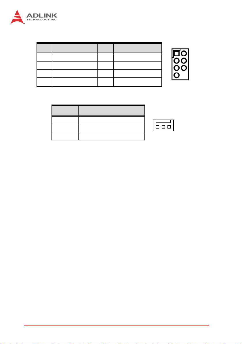
ATX 12V Power Connector (ATX12V1)
Pin # Signal
1 GND
2 GND
3 +12V DC
4 +12V DC
Serial Port Connectors - RS-232 (COM2~6)
Pin # Signal Function
1 DCD Data Carrier Detect
2 DSR Data Set Ready
3 RXD Receive Data
4 RTS Request to Send
5 TXD Transmit Data
6 CTS Clear to Send
7 DTR Data Terminal Ready
8 RI Ring Indicate
9 GND Ground
10 NC Key
2
4
AD-mITX-T40H
1
3
21
CPU Fan Connector (CPU_FAN1)
Pin # Signal
1GND
2+12V
3Tach
4PWM
Connectors & Jumpers 13
14
Page 26

ATX Power Connector (EATXPWR1)
Pin # Signal Pin # Signal
1 +3.3V 13 +3.3V
2 +3.3V 14 -12V
3 GND 15 GND
4 +5V 16 PS-ON#
5 GND 17 GND
6 +5V 18 GND
7 GND 19 GND
8 PWRGD 20 NC
9 +5VSB 21 +5V
10 +12V 22 +5V
11 +12V 23 +5V
12 +3.3V 24 GND
System Panel Header (F_PANEL)
Pin # Signal Function
1 HDDLED+ HDD Activity
2 POWERLED+ Power LED
3 HDDLED- HDD Activity
4 POWERLED- Power LED
5 GND Reset Button
6 PWSWITCH ATX Power/Soft-off Button
7 RESET Reset Button
8 GND ATX Power/Soft-off Button
9 NC Not Connected
10 NC Key
12
24
1
13
21
14 Connectors & Jumpers
Page 27
Front Panel Audio Pin Header (FPAUD1)
Pin # Signal Pin # Signal
1 MIC2_L 2 GND
3 MIC2_R 4 PRESENSE
5 LIN2_R 6 MIC2_JD
7 FIO_SENSE A 8 NC
9 LIN2_L 10 LINE_JD
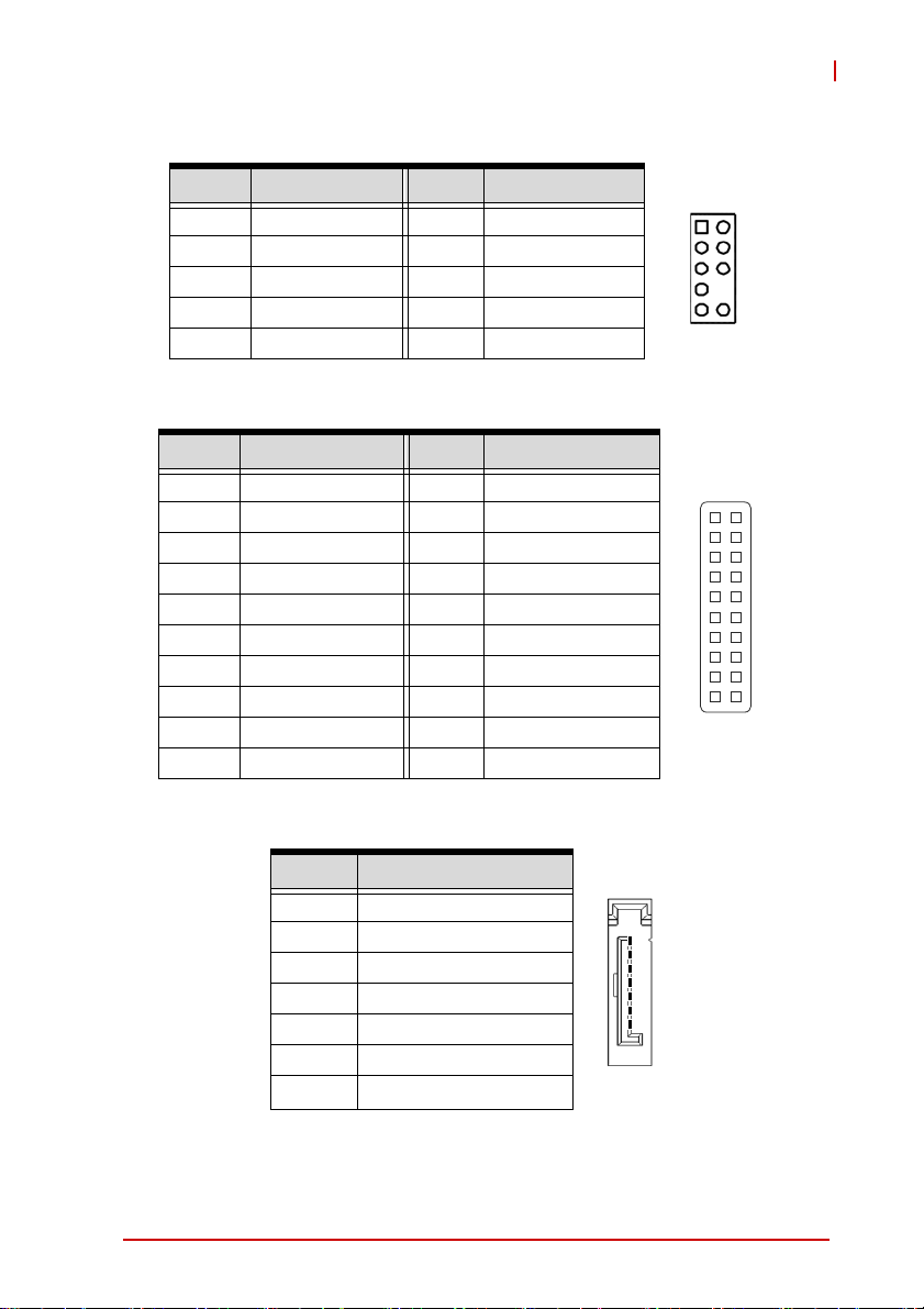
GPIO Connector (JDIO)
Pin # Signal Pin # Signal
1 SIO_GPIO0 2 SIO_GPIO8
3 SIO_GPIO1 4 SIO_GPIO9
5 SIO_GPIO2 6 SIO_GPIO10
7 SIO_GPIO3 8 SIO_GPIO11
9 SIO_GPIO4 10 SIO_GPIO12
11 SIO_GPIO5 12 SIO_GPIO13
13 SIO_GPIO6 14 SIO_GPIO14
15 SIO_GPIO8 16 SIO_GPIO15
17 SMB_CLK_MAIN 18 SMB_DAT_MAIN
19 GND 20 +5V_SB
AD-mITX-T40H
21
1
19 20
2
SATA Connectors (SATA1~2)
Pin # Signal
1 GND
2 TXP
3 TXN
4 GND
5 RXN
6 RXP
7 GND
Connectors & Jumpers 15
1
7
Page 28
SPI Header (SPI1)
Pin # Signal Pin # Signal
1 +3V ROM 2 GND
3 SPI_CS# 4 SPI_CLK
5 SPI_MISO 6 SPI_MOSI
7 SPI_HOLD# 8 Key
System Fan Connector (SYS_FAN)
Pin # Signal
1 GND
2 VCC (PWM)
3 IO
1
13
16 Connectors & Jumpers
Page 29
AD-mITX-T40H
2.4 Jumpers
Clear CMOS (JCMOS1)
This jumper allows you to clear the Real Time Clock (RTC) RAM in
CMOS (date, time, and system setup parameters). The onboard
button cell battery powers the RAM data in CMOS, which includes
system setup information such as system passwords.
To erase the RTC RAM:
1. Turn OFF the computer and unplug the power cord.
2. Remove the onboard battery.
3. Move the jumper cap from pins 1-2 (default) to pins 2-3.
Keep the cap on pins 2-3 for about 5~10 seconds, then
move the cap back to pins 1-2.
4. Re-install the battery.
5. Plug the power cord and turn ON the computer.
6. Hold down the <Del> key during the boot process and
enter BIOS setup to re-enter data.
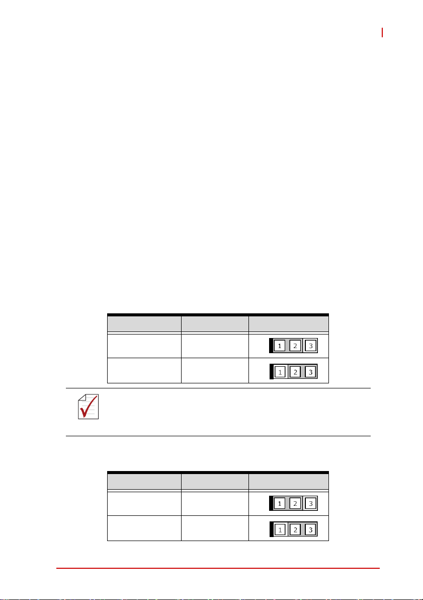
Mode Connection PWR_JP1
+5 1 – 2
RI# 2 – 3
Except when clearing the RTC RAM, never remove the cap on
Clear CMOS jumper from its default position. Removing the
NOTE:
NOTE:
cap will cause a system boot failure.
AT/ATX Power Mode Select (JPSON)
Mode Connection PWR_JP1
ATX Mode 1 – 2
AT Mode 2 – 3
Connectors & Jumpers 17
Page 30

This page intentionally left blank.
18 Connectors & Jumpers
Page 31

AD-mITX-T40H
3 Getting Started
This chapter provides information on how to install components on
the AD-mITX-T40H motherboard.
3.1 Installing the CPU
The AD-mITX-T40H supports a 22/32nm Intel® Xeon®
E3-1275/1225, Core™ i7/i5/ i3, Pentium/Celeron® processor in an
LGA1155 socket.
Disconnect all power to the board before installing a CPU to
prevent damaging the board and CPU.
WARNING:
To install the CPU:
Do not touch socket contacts. Damaging the contacts voids the
product warranty. Follow the installation instructions carefully to
avoid damaging the board components.
1. Press down on the locking arm (A), then push it away from
the socket to disengage it from the retention tab (B).
A
B
Getting Started 19
Page 32

2. Raise the locking arm to unlock the load plate.
3. Lift the load plate to uncover the socket.
4. Remove the plastic protective cover from the socket. Note the
locations of the alignment keys (A) and Pin 1 indicator (B).
B
A
Do NOT touch socket contacts.
WARNING:
20 Getting Started
Page 33

AD-mITX-T40H
5. Hold the CPU using thumb and forefinger as shown. Position the
CPU over the socket, matching the notches on the sides of the
CPU with the alignment keys on the socket (A). The golden triangle on the CPU must be positioned at the corner of the socket
with the Pin 1 indicator as shown (B).
AB
The CPU fits into the socket in only one orientation. DO NOT
force it into the socket to avoid causing damage.
WARNING:
6. Carefully place the CPU into the socket vertically. The socket has
cutouts for your fingers to fit into.
Cutouts
Getting Started 21
Page 34

7. Gently lower the load plate. Make sure the front edge of the
plate is under the screw as indicated.
8. Lower the locking arm and fasten it to the retention tab (A).
The load plate should be locked underneath the screw as
shown (B).
B
A
22 Getting Started
Page 35

AD-mITX-T40H
3.2 Installing the CPU Fan and Heatsink
The CPU requires a chassis with an airflow inlet. A specially-designed CPU fan and heatsink must be installed before
CAUTION:
When the CPU fan installation procedures presented here are
inconsistent with the installation procedures you obtained from the
CPU fan and heatsink package, follow the latter.
To install the CPU fan:
using the motherboard. Failure to install a CPU fan and heatsink may damage the system host board and/or the CPU.
1. Apply thermal grease evenly on top of the installed CPU.
2. Lower the CPU fan to the CPU, then secure it using the provided
attachments or screws.
3. Connect the CPU fan cable to the CPU fan connector on the
motherboard labeled FAN1 (see CPU Fan Connector
(CPU_FAN1) on page 13).
Getting Started 23
Page 36

3.3 System Memory
The AmITX-IB-I supports up to 16 GB of DDR3-1066/1333
SDRAM in two 204-pin SO-DIMM sockets. See Figure 2-1 on
page 7 for SO-DIMM socket locations.
Memory Module Installation
The DDR3 memory modules are notched to facilitate correct
installation in the DIMM sockets.
Disconnect all power supply to the board before installing a
memory module to prevent damaging the board and mem-
WARNING:
To install a memory module:
1. Unlock the SO-DIMM socket by pressing the retaining
ory module .
clips outward.
2. Align the memory module on the socket, making sure that the
notch matches the break on the socket.
DDR3 SO -DI MM Not ch
Unlocked retaining clip
24 Getting Started
Page 37

AD-mITX-T40H
3. Insert the module firmly into the slot until the retaining clips
snap back inwards and the module is securely seated.
Unlocked retaining clip
Getting Started 25
Page 38

3.4 Driver Installation
The AmITX-IB-I drivers for Windows 7 32-bit are located in the
following directories on the Driver CD, or can be downloaded from
the ADLINK website (http://www.adlinktech.com):
Chipset X:\AmITX-IB-I_Driver\CHIP\
Display X:\AmITX-IB-I_Driver\VGA\Ivy Bridge\
VGA_driver_intel_Integrated_Graphics
_Windows7_64bit\
LAN X:\AmITX-IB-I_Driver\LAN\Win7\Network_driver_Realtek
_Network_Adapter for Windows 7\
Audio X:\AmITX-IB-I_Driver\Audio_driver_Realtek_Windows 7\
USB 3.0 X:\AmITX-IB-I_Driver\USB 30_driver_Renesas
_All_WinOS\
Follow the instructions below to install the required AmITX-IB-I
drivers. Install the Windows operating system before installing any
driver. Most standard I/O device drivers are installed during Windows installation.
1. Install the Chipset driver by running the program
X:\AmITX-IB-I_Driver\CHIP\Chipset driver_Intel_INF_
Update_Utility_All_WinOS\infinst_autol_9.2.0.1030.exe.
Follow the instructions given and reboot when instructed.
2. Install the Display driver and utilities by running the program
X:\AmITX-IB-I_ Driver\VGA\Ivy Bridge\ VGA_driver_intel_
Integrated_Graphics_Windows7_64bit\Setup.exe. Follow the
instructions given and reboot when instructed.
3. Install the LAN driver by running the program
X:\AmITX-IB-I_ Driver\LAN\ Network_driver_Realtek_
Network_Adapter for Windows 7\Setup.exe. Follow the
instructions given and reboot if required.
4. Install the Audio driver by running the program
X:\AmITX-IB-I_ Driver\Audio_driver_Realtek_Windows 7\
64Bit\64bit_Vista_Win7_Win8_R270.exe. Follow the instruc-
tions given and reboot if required.
26 Getting Started
Page 39

AD-mITX-T40H
5. Install the USB 3.0 driver by running the program X:\AmITX-IB-I_
Driver\USB 30_driver_Renesas_All_WinOS\ Setup.exe. Fol-
low the instructions given and reboot if required.
Getting Started 27
Page 40

This page intentionally left blank.
28 Getting Started
Page 41

AD-mITX-T40H
4 BIOS Setup
4.1 Introduction
This section explains how to use the UEFI Setup Utility to
configure your system. The UEFI chip on the motherboard stores
the UEFI Setup Utility. You may run the UEFI Setup Utility when
you start the computer. Please press <F2> or <Del> during the
Power-On-Self-Test (POST) to enter the UEFI Setup Utility,
otherwise POST will continue with its test routines.
If you wish to enter the UEFI Setup Utility after POST, restart the
system by pressing <Ctl> + <Alt> + <Delete>, or by pressing the
reset button on the system chassis. You may also restart by
turning the system off and then back on.
Because the UEFI software is constantly being updated, the
following UEFI setup screens and descriptions are for refer-
NOTE:
NOTE:
4.1.1 UEFI Menu Bar
ence purposes only, and they may not exactly match what you
see on your screen.
The top of the screen has a menu bar with the following selections:
X Main: To set up the system time/date information
X Advanced: To set up the advanced UEFI features
X Chipset: To set up advanced chipset features
X Boot: To set up the default system device to locate and load
the Operating System
X Security: To set up the security features
X Exit: To exit the current screen or the UEFI Setup Utility
Use the < ← > key or < → > key to choose between the selections
on the menu bar, and then press <Enter> to get into the sub
screen. You can also use the mouse to choose your required item
by clicking.
BIOS Setup 29
Page 42

4.1.2 Navigation
The following table describes the functions of each navigation key.
Key(s) Function Description
← / → Moves cursor left or right to select Screens
↑ / ↓ Moves cursor up or down to select items
+ / - Choose between options of the selected item
<Enter> Bring up the selected screen
<F1> Display the General Help Screen
<F7> Discard changes
<F9> Load optimal default values for all settings
<F10> Save changes and exit the UEFI Setup Utility
<F12> Print screen
<Esc> Jump to the Exit Screen or exit the current screen
30 BIOS Setup
Page 43
AD-mITX-T40H
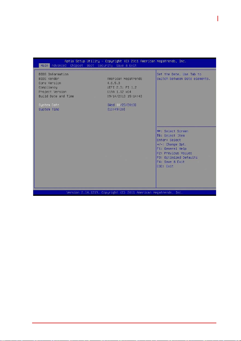
4.2 Main Setup
When you enter the UEFI Setup Utility, the Main screen will
appear and display the system overview.
BIOS Setup 31
Page 44
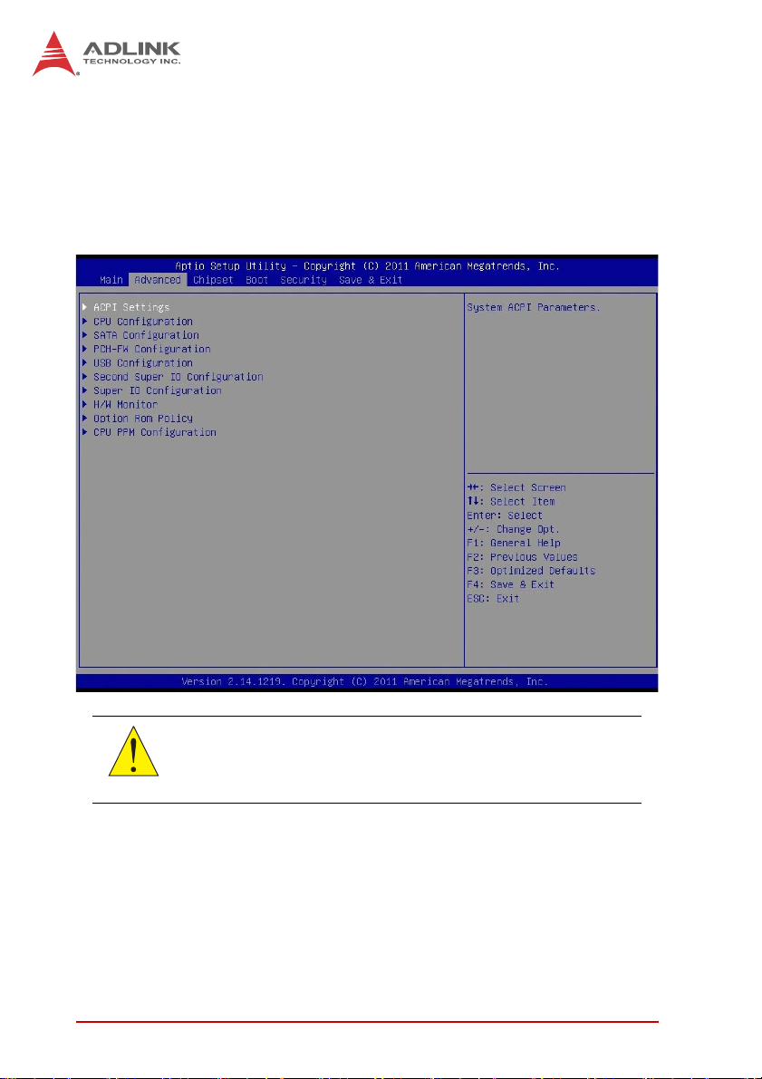
4.3 Advanced Setup
In this section, you may set the configurations for the following
items: ACPI Configuration, CPU Configuration, SATA Configuration, PCH-FW Configuration, USB Configuration, Second Super
IO Configuration, Super IO Configuration, H/W Monitor Option
Rom Policy and CPU PPM Configuration.
Setting incorrect values in this section may cause the system
to malfunction.
CAUTION:
32 BIOS Setup
Page 45

4.3.1 ACPI Configuration
AD-mITX-T40H
ACPI sleep State
Use this option to select whether to auto-detect or disable the Suspend-to- RAM feature. Selecting [Auto] will enable this feature if
the OS supports it.
S3 Video Repost
Use this to enable/disable S3 Video Repost. The default value is
[Enabled].
RTC Alarm Power On
Use this option to enable/disable RTC (Real Time Clock) alarm to
power on the system.
BIOS Setup 33
Page 46

Wake on PCIE
Use this option to enable or disable PCIE wake event to power on
the system.
4.3.2 CPU Configuration
Intel Hyper-Threading Technology
Enabling this feature requires a computer system with an Intel processor that supports Hyper-Threading Technology and an operating system that includes optimization for this technology, such as
Microsoft Windows 7. Set to [Enabled] if using Microsoft® Windows® 7.
Intel Virtualization Technology
When enabled, a Virtual Machine Monitor (VMM) can utilize the
additional hardware capabilities provided by Vanderpool Technology.
34 BIOS Setup
Page 47

4.3.3 SATA Configuration
AD-mITX-T40H
SATA Controller(s)
Enables or disables SATA devices.
SATA Mode
Use this to select the SATA mode. Configuration options: [IDE
Mode], [AHCI Mode]. The default value is [IDE Mode].
AHCI (Advanced Host Controller Interface) supports NCQ and
other new features that improves SATA disk performance. IDE
NOTE:
NOTE:
BIOS Setup 35
mode does not support these features.
Page 48

4.3.4 PCH-FW Configuration
36 BIOS Setup
Page 49

4.3.5 USB Configuration
AD-mITX-T40H
Legacy USB Support
Use this option to select legacy support for USB devices. There
are three configuration options: [Enabled], [Disabled] and [Auto].
The default value is [Enabled]. Please refer to the following
descriptions for details of these three options:
X [Enabled]: Enables support for legacy USB.
X [Auto]: Enables legacy support if USB devices are con-
nected.
X [Disabled]: USB devices are disabled under legacy OS
setup.
BIOS Setup 37
Page 50

4.3.6 Second Super IO Configuration
Serial Port 3~6 Configuration
Use this option to set parameters of COM3~6.
38 BIOS Setup
Page 51

4.3.7 Super IO Configuration
AD-mITX-T40H
Serial Port 1~2 Configuration
Use this option to set parameters of COM1~2.
Watch D og Timer
This allows users to enable/disable the Watchdog Timer timeout to
reset system. The default value is [Disabled].
RS232/422/485 Selection
Select COM Port type for RS-232, RS-422 or RS-485.
BIOS Setup 39
Page 52

4.3.8 H/W Monitor
Smart Fan Mode Configuration
Smart Fan Mode Select.
40 BIOS Setup
Page 53

4.3.9 Option ROM Policy
AD-mITX-T40H
Boot Option Filter
This option controls what devices the system can boot from.
Launch PXE OpROM policy
Controls the execution of UEFI and Legacy PXE Option ROM.
Launch Storage OpROM policy
Controls the execution of UEFI and Legacy Storage Option ROM.
BIOS Setup 41
Page 54

4.3.10 CPU PPM Configuration
EIST
Enable/Disable Intel SpeedStep.
Turbo Mode
Turbo Mode.
42 BIOS Setup
Page 55

4.4 Chipset Setup
AD-mITX-T40H
BIOS Setup 43
Page 56

4.4.1 PCH-IO Configuration
44 BIOS Setup
Page 57
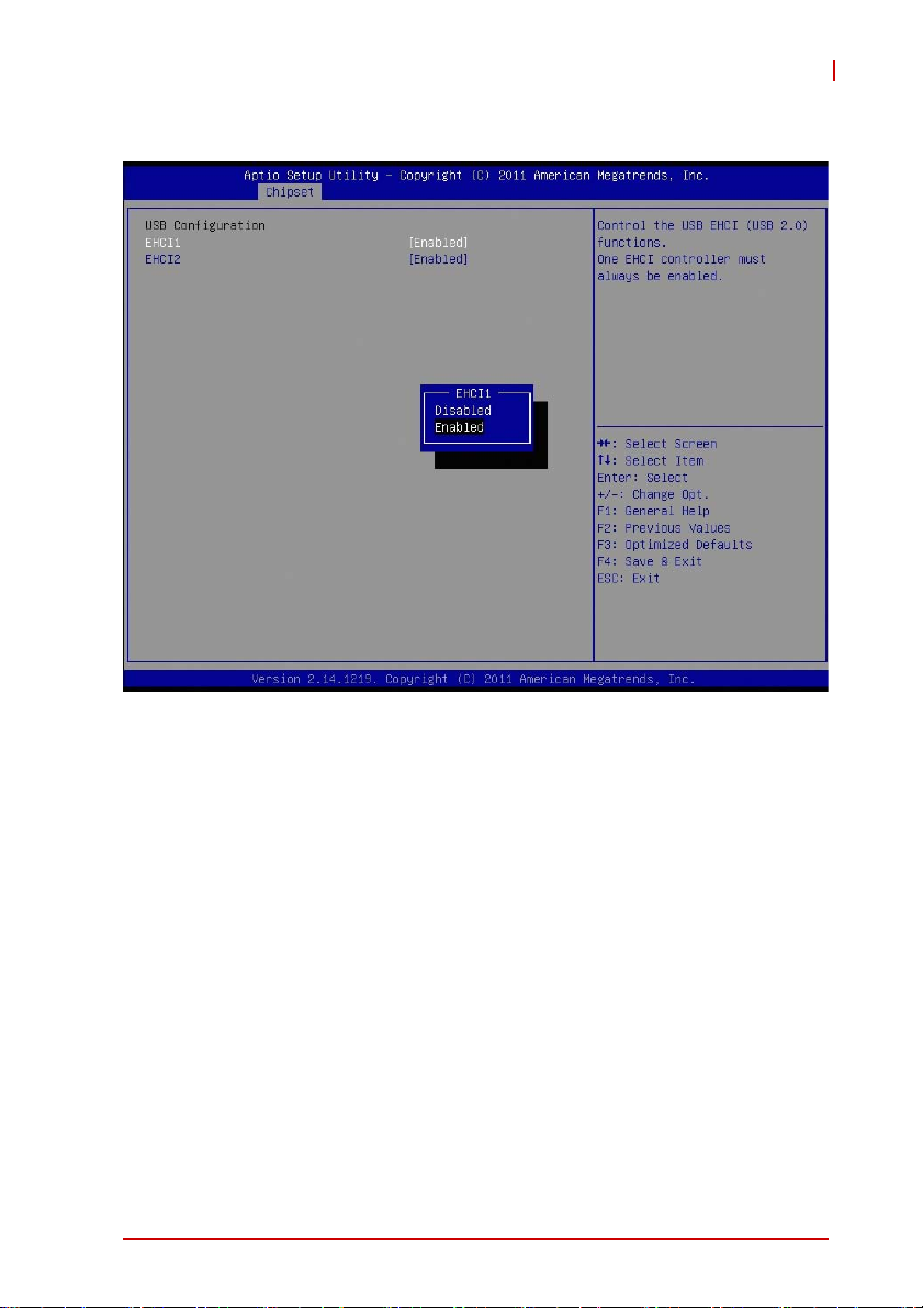
USB Configuration
AD-mITX-T40H
EHCI1/2
Controls the USB EHCI (USB 2.0) functions. One EHCI controller must always be enabled.
BIOS Setup 45
Page 58
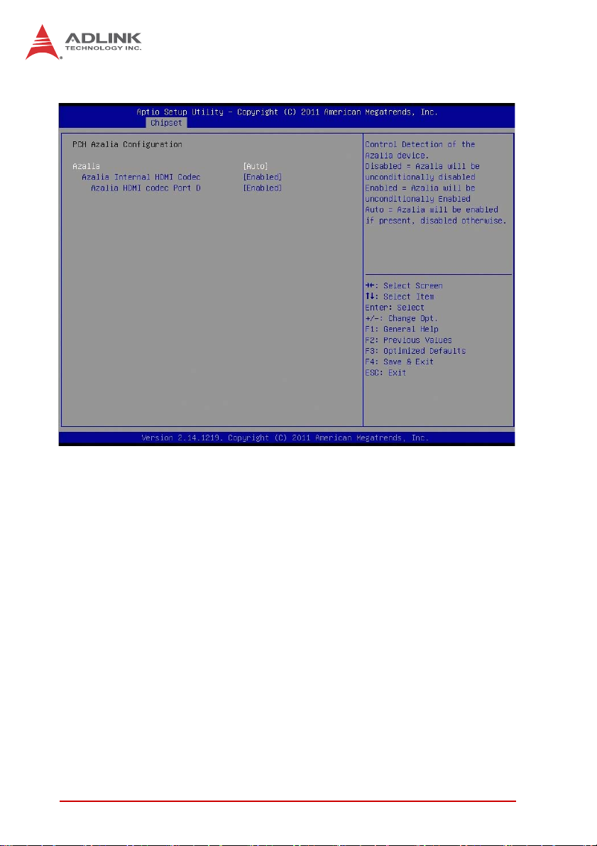
PCH Azalia Configuration
Azalia
Controls detection of the Azalia device.
X [Disabled]: Azalia will be unconditionally disabled.
X [Enabled]: Azalia will be unconditionally enabled.
X [Auto]: Azalia will be enabled if present, disabled otherwise.
46 BIOS Setup
Page 59

4.4.2 System Agent (SA) Configuration
AD-mITX-T40H
BIOS Setup 47
Page 60

Graphics Configuration
Primary Display
Select which graphics device should be Primary Display
(IGFX/PEG/PCI), or select SG for switchable graphics.
Internal Graphics
Keep IGD enabled based on the setup options.
DVMT Pre-Allocated
Select DVMT 5.0 Pre-Allocated (Fixed) Graphics Memory size
used by the Internal Graphics Device.
DVMT Total Gfx Mem
Select DVMT5.0 Total Graphic Memory size used by the Internal
Graphics Device.
48 BIOS Setup
Page 61

LCD Control
AD-mITX-T40H
Primary IGFX Boot Display
Select the Video Device which will be activated during POST.
This has no effect if external graphics is present. Secondary
boot display will appear based on your selection. VGA modes
will be supported only on the primary display
BIOS Setup 49
Page 62
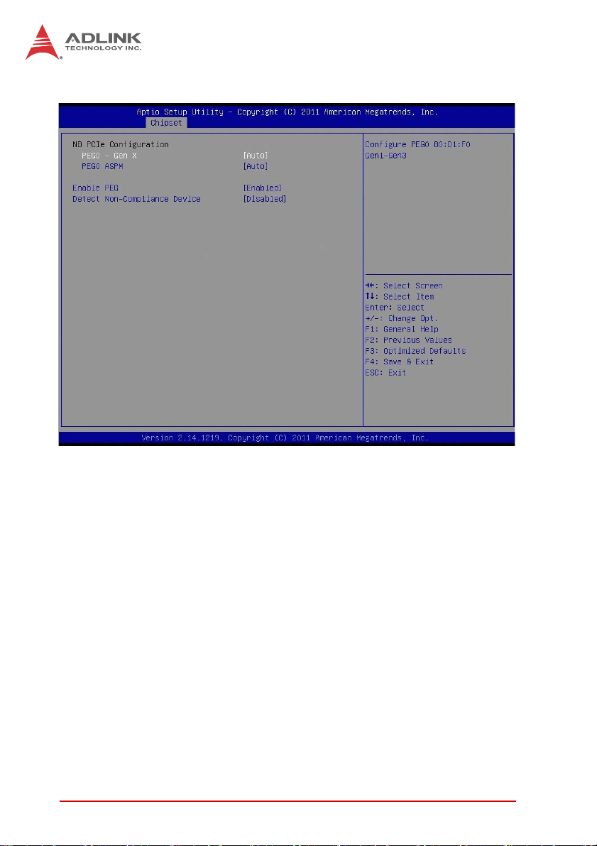
NB PCIe Configuration
PEG0 - Gen X
Configure PEG0 B0:D1:F0 Gen1-Gen3
PEG0 ASPM
Control ASPM support for the PEG: Device1 Function 0.This
has no effect if PEG is not the currently active device.
Enable PEG
Enable or disable the PEG.
Detect Non-Compliance Device
Detect non-compliant PCI Express device in PEG.
50 BIOS Setup
Page 63
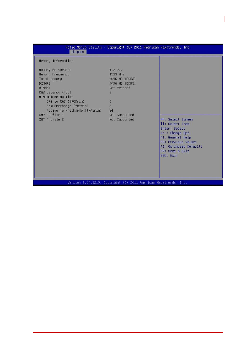
Memory Configuration
AD-mITX-T40H
BIOS Setup 51
Page 64

4.5 Boot Setup
This section of the BIOS settings displays the available devices on
your system for configuring the boot settings and boot priority.
Setup Prompt Timeout
This shows the number of seconds to wait for the setup activation
key; 65535(0XFFFF) means wait indefinitely.
Bootup Num-Lock State
If this item is set to [On], it will automatically activate the Numeric
Lock function after boot-up.
Quiet Boot
Enable or disable the Quiet Boot option.
52 BIOS Setup
Page 65

AD-mITX-T40H
4.6 Security Setup
This section of the BIOS settings enables you to set, change or
clear the supervisor/user password for the system.
Administrator Password
Set Administrator Password
User Password
Set User Password
BIOS Setup 53
Page 66

4.7 Save & Exit Menu
Save Changes and Exit
Selecting this option will display the message "Save configuration
changes and exit setup?" Select [OK] to save changes and exit
the UEFI Setup Utility.
Discard Changes and Exit
Selecting this option will display the message "Discard changes
and exit setup?" Select [OK] to exit the UEFI Setup Utility without
saving any changes.
Save changes and Reset
Reset the system after saving changes.
Restore Defaults
Restore/Load Default values for all setup options.
54 BIOS Setup
Page 67

AmITX-IB-I
Appendix A -
Super IO Programming Guide
The programming instructions for the AmITX-IB-I’s Super IO are
as follows.
void SIOEnterConfig(void)
{
outportb(bSIO_CONFIG_INDEX_PORT,
bSIO_CONFIG_ENTER_KEY);
outportb(bSIO_CONFIG_INDEX_PORT,
bSIO_CONFIG_ENTER_KEY);
return;
}
void SIOExitConfig(void)
{
outportb(bSIO_CONFIG_INDEX_PORT,
bSIO_CONFIG_EXIT_KEY);
return;
}
void SIOWrite(char bIndex, char bValue)
{
outportb(bSIO_CONFIG_INDEX_PORT,
bSIO_CONFIG_EXIT_KEY);
return;
}
void SIORead(char bIndex, char bValue)
{
outportb(bSIO_CONFIG_INDEX_PORT,
bSIO_CONFIG_EXIT_KEY);
return;
}
Programming steps: Use QM67 as example.
SIO_CONFIG_INDEX_PORT = 2Eh (QM67 uses 2Eh)
SIO_CONFIG_DATA_PORT = 2Fh
SIO_CONFIG_ENTER_KEY = 87h (Please check SIO datasheet)
SIO_CONFIG_EXIT_KEY = AAh (Please check SIO datasheet)
Super IO Programming Guide 55
Page 68

A.1 Program GPIO Function to Output
// before SIO programming, must enter config mode. //
SIOEnterConfig(); Enter SIO configure mode.
// bIndex = 07h as logical device selection register.
// bValue = 07h as logical device number (QM67 uses
GPIO 6)
SIOWrite(0x07, 0x07); Select to Logical Device 7
// bIndex = F4h as control register
// bValue = 00h as output enabled.
SIOWrite(0xF4, 0x00); Set all GPI/O to output.
GPIO Function to AllOutput High
// bIndex = F5h as output register
// bValue = FFh as output level high
SIOWrite(0xF4, 0x00); set all GPI/O to output.
GPIO function to All Output Low
// bIndex = F5h as output register
// bValue = 00h as output level high
SIOWrite(0xF5, 0x00); set all GPI/O to output.
GPIO function to Output High (GPIOx)
// bIndex = F5h as output register
bValue = SIORead(0xF5); read back output register
bValue |= 1 << x; x means GPIO number.
SIOWrite(0xF5, bValue); set GPI/Ox to output high.
GPIO function to Output Low (GPIOx)
// bIndex = F5h as output register
bValue = SIORead(0xF5); read back output register
bValue &= ~(1 << x); x means GPIO number
SIOWrite(0xF5, bValue); set GPI/Ox to output low.
// after SIO programming, must exit config mode. //
SIOExitConfig(); Exit SIO configure mode.
56 Super IO Programming Guide
Page 69

AmITX-IB-I
A.2 Program GPIO Function to Input
// before SIO programming, must enter config mode. //
SIOEnterConfig(); Enter SIO configure mode.
// bIndex = 07h as logical device selection register.
// bValue = 07h as logical device number (QM67 uses
GPIO 6)
SIOWrite(0x07, 0x07); Select to Logical Device 7
// bIndex = F4h as control register
// bValue = FFh as input enabled.
SIOWrite(0xF4, 0xFF); set all GPI/O to input
Read back GPIO Input Status
// bIndex = F5h as input register.
bValue = SIORead(0xF5); read back input register
// bValue = GPI/O input status.
// after SIO programming, must exit config mode. //
SIOExitConfig(); Exit SIO configure mode.
Super IO Programming Guide 57
Page 70

A.3 Watchdog Sample Code
TOKEN
Name = "NCT6776F_CONFIG_INDEX"
Value = "0x2E"
TokenType = Integer
TargetEQU = Yes
TargetH = Yes
End
TOKEN
Name = "NCT6776F_CONFIG_MODE_ENTER_VALUE"
Value = "0x87"
Help = "Value to enter Configuration Mode.Please
check your hardware"
TokenType = Integer
TargetH = Yes
End
TOKEN
Name = "NCT6776F_CONFIG_MODE_EXIT_VALUE"
Value = "0xAA"
Help = "Value to EXIT Configuration Mode.Please
check your hardware"
TokenType = Integer
TargetH = Yes
End
void Oem_WDT_Init (
IN SETUP_DATA *SetupData
)
{
IoWrite8 (NCT6776F_CONFIG_INDEX ,
NCT6776F_CONFIG_MODE_ENTER_VALUE);
IoWrite8 (NCT6776F_CONFIG_INDEX ,
NCT6776F_CONFIG_MODE_ENTER_VALUE);
IoWrite8 (NCT6776F_CONFIG_INDEX , 0x2B);
// Pin80 function selection to GP34
Data8 = IoRead8(NCT6776F_CONFIG_DATA) | 0x10;
IoWrite8 (NCT6776F_CONFIG_DATA , Data8);
58 Super IO Programming Guide
Page 71

AmITX-IB-I
IoWrite8 (NCT6776F_CONFIG_INDEX ,
NCT6776F_LDN_SEL_REGISTER); //LDN 0x09
IoWrite8 (NCT6776F_CONFIG_DATA , NCT6776F_LDN_GPIO3);
IoWrite8 (NCT6776F_CONFIG_INDEX ,
NCT6776F_ACTIVATE_REGISTER); //CR 30h
Data8 = IoRead8(NCT6776F_CONFIG_DATA) | 0x08;
IoWrite8 (NCT6776F_CONFIG_DATA , Data8);
IoWrite8 (NCT6776F_CONFIG_INDEX , 0xE4);
//Set GP34 to output mode
Data8 = IoRead8(NCT6776F_CONFIG_DATA) & 0xEF;
IoWrite8 (NCT6776F_CONFIG_DATA , Data8);
IoWrite8 (NCT6776F_CONFIG_INDEX , 0xE5);
//Set GP34 to output High
Data8 = IoRead8(NCT6776F_CONFIG_DATA) | 0x10;
IoWrite8 (NCT6776F_CONFIG_DATA , Data8);
IoWrite8 (NCT6776F_CONFIG_INDEX , 0xEA);
// selection Pin 34 to WDTO
Data8 = IoRead8(NCT6776F_CONFIG_DATA) | 0x10;
IoWrite8 (NCT6776F_CONFIG_DATA , Data8);
IoWrite8 (NCT6776F_CONFIG_INDEX ,
NCT6776F_LDN_SEL_REGISTER); //LDN 0x08
IoWrite8 (NCT6776F_CONFIG_DATA , NCT6776F_LDN_GPIO2);
IoWrite8 (NCT6776F_CONFIG_INDEX ,
NCT6776F_ACTIVATE_REGISTER); //CR 30h
Data8 = IoRead8(NCT6776F_CONFIG_DATA) |
gSetup.WDT_Control; //VC312D+
IoWrite8 (NCT6776F_CONFIG_DATA , Data8);
//VC312D+
IoWrite8(NCT6776F_CONFIG_INDEX, 0xF5);
//Watchdog Timer: CR F5h Bit3
Data8 = IoRead8(NCT6776F_CONFIG_DATA) |
gSetup.WDT_CountMode;
IoWrite8 (NCT6776F_CONFIG_DATA , Data8);
Super IO Programming Guide 59
Page 72

IoWrite8(NCT6776F_CONFIG_INDEX, 0xF6);
//Watchdog Timer Counter Register
IoWrite8(NCT6776F_CONFIG_DATA, gSetup.WDT_TimeOut);
IoWrite8 (NCT6776F_CONFIG_INDEX ,
NCT6776F_CONFIG_MODE_EXIT_VALUE);
}
60 Super IO Programming Guide
Page 73

Appendix B - System Resources
B.1 System Memory Map
AmITX-IB-I
Address Range
(decimal)
(4GB-2MB)
(4GB-18MB) –
(4GB-17MB-1)
(4GB-20MB) –
(4GB-19MB-1)
960 K – 1024 K F0000 – FFFFF 64 KB System BIOS Area
896 K – 960 K E0000 – EFFFF 64 KB Extended System BIOS Area
768 K – 896 K C0000 – DFFFF 128 KB PCI expansion ROM area
640 K – 768 K A0000 – BFFFF 128 KB Video Buffer & SMM space
0 K – 640 K 00000 – 9FFFF 640 KB DOS Area
0 K – 640 K 00000 – 9FFFF 640 KB DOS Area
Address Range
(hex)
FFE00000 –
FFFFFFFF
FEE00000 –
FEEFFFFF
FEC00000 –
FECFFFFF
Table B-1: System Memory Map
Size Description
2 MB High BIOS Area
1 MB FSB Interrupt Memory Space
1 MB APIC Configuration Space
B.2 Direct Memory Access Channels
Channel Number Data Width System Resource
0– Open
1– Open
2– Open
3 – Open
4 – DMA Controller
5– Open
6– Open
7– Open
Table B-2: Direct Memory Access Channels
System Resources 61
Page 74

B.3 I/O Map
Hex Range Device
000-00F DMA controller 1
020-021 Programmable interrupt controller
024-025 Programmable interrupt controller
028-029 Programmable interrupt controller
02C-02D Programmable interrupt controller
030-031 Programmable interrupt controller
034-035 Programmable interrupt controller
038-039 Programmable interrupt controller
03C-03D Programmable interrupt controller
040-043 System timer
050-053 System timer
060, 064 8742 equivalent (keyboard)
061 System speaker
070-077 System CMOS/Real time clock
081-091 DMA page register
093-09F DMA page registers continued
0A0-0B1 and 0B4-0BD Interrupt controller 2, 8259 equivalent
0C0-0DF DMA controller 2, 8237A-5 equivalent
0F0-0FF Math Processor
2E0 – 2E7 Serial Port 5
2E8 – 2EF Serial Port 4
2F0– 2F7 Serial Port 6
2F8 – 2FF Serial Port 2
170-177 and 1F0-1F7
376 and 3F6
3B0 – 3BB Mono/VGA mode video
3C0- 3DF VGA registers
3E8 – 3EF Serial Port 3
3F8 – 3FF Serial Port 1
4D0 and 4D1 Interrupt controller
D00-0FFFF PCI bus
D000-D0FF Realtek GBE Controller #2
ATA Channel 0
62 System Resources
Page 75

Hex Range Device
D000-DFFF PCI-to-PCI Bridge
E000-E0FF Realtek GBE Controller #1
E000-EFFF PCI-to-PCI Bridge
F000-F03F Intel(R) HD Graphics
F040-F05F Smbus Controller
F060-F07F
F080-F083
F090-F097
F0A0-F0A3
F0B0-F0B7
Table B-3: I/O Map
SATA AHCI Controller
AmITX-IB-I
System Resources 63
Page 76

B.4 Interrupt Request (IRQ) Lines
IRQ# Typical Interrupt Resource Connected to Pin
0 System Timer N/A
1 Keyboard controller N/A
2N/A N/A
3
4
5
6N/A N/A
7N/A N/A
8 Real-time clock N/A
9N/A N/A
10
11 N/A N/A
12 N/A N/A
13 Math Processor N/A
14 N/A N/A
15 N/A N/A
16
17 PCI-to-PCI bridge N/A
18 N/A N/A
19 N/A N/A
20 N/A N/A
21 N/A N/A
22 High Definition Audio Contoller N/A
23 AHCI SATA Contoller N/A
Serial Port 2 (COM2) / PCI /
ISA
Serial Port 1 (COM1) / PCI /
ISA
Serial Port 3, 4 (COM3,4) / PCI
/ ISA
Serial Port 5 (COM5,6) / PCI /
ISA
PCI-to-PCI bridge, PCI-to-USB
Host Controller
IRQ3 via SERIRQ, IRQ3 at
ISA bus
IRQ4 via SERIRQ, IRQ4 at
ISA bus
IRQ5 via SERIRQ, IRQ5 at
ISA bus
IRQ10 via SERIRQ, IRQ10 at
ISA bus
N/A
T ab le B-4: IRQ Lines APIC Mode
64 System Resources
Page 77

B.5 PCI Configuration Space Map
AmITX-IB-I
Bus
Number
00h 00h 00h N/A Intel Host Bridge
00h 01h 00h Internal PCI Express Root Port
00h 02h 00h Internal Intel Integrated Graphics Device
00h 16h 00h Internal Intel Management Engine Interface
00h 1Ah 00h Internal Intel USB EHCI Controller #2
00h 1Bh 00h Internal High Definition Audio controller
00h 1Ch 00h Internal PCI Express Root port 1
00h 1Ch 01h Internal PCI Express Root port 2
00h 1Ch 04h Internal PCI Express Root port 5
00h 1Ch 05h Internal PCI Express Root port 6
00h 1Dh 00h Internal Intel USB EHCI Controller #1
00h 1Fh 00h N/A Intel ISA Interface Bridge
00h 1Fh 02h Internal Intel AHCI controller
00h 1Fh 03h Internal Intel SMBus Controller
00h 1Fh 05h Internal Intel SATA controller #2
03h 00h 00h Internal USB Controller(PCI Express)
04h 00h 00h Internal Realtek Ethernet (PCI Express)
05h 00h 00h Internal Realtek Ethernet (PCI Express)
Device
Number
Function
Number
Table B-5: PCI Configuration Space Map
Routing Description
System Resources 65
Page 78

This page intentionally left blank.
66 System Resources
Page 79

AmITX-IB-I
Important Safety Instructions
For user safety, please read and follow all instructions,
WARNINGS, CAUTIONS, and NOTES marked in this manual
and on the associated equipment before handling/operating the
equipment.
X Read these safety instructions carefully.
X Keep this user’s manual for future reference.
X Read the specifications section of this manual for detailed
information on the operating environment of this equipment.
X When installing/mounting or uninstalling/removing
equipment:
Z Turn off power and unplug any power cords/cables.
X To avoid electrical shock and/or damage to equipment:
Z Keep equipment away from water or liquid sources;
Z Keep equipment away from high heat or high humidity;
Z Keep equipment properly ventilated (do not block or
cover ventilation openings);
Z Make sure to use recommended voltage and power
source settings;
Z Always install and operate equipment near an easily
accessible electrical socket-outlet;
Z Secure the power cord (do not place any object on/over
the power cord);
Z Only install/attach and operate equipment on stable
surfaces and/or recommended mountings; and,
Z If the equipment will not be used for long periods of time,
turn off and unplug the equipment from its power source.
Important Safety Instructions 67
Page 80

X Never attempt to fix the equipment. Equipment should only
be serviced by qualified personnel.
A Lithium-type battery may be provided for uninterrupted, backup
or emergency power.
Risk of explosion if battery is replaced with one of an incorrect
WARNING:
type. Dispose of used batteries appropriately.
X Equipment must be serviced by authorized technicians
when:
Z The power cord or plug is damaged;
Z Liquid has penetrated the equipment;
Z It has been exposed to high humidity/moisture;
Z It is not functioning or does not function according to the
user’s manual;
Z It has been dropped and/or damaged; and/or,
Z It has an obvious sign of breakage.
68 Important Safety Instructions
Page 81

Getting Service
Contact us should you require any service or assistance.
ADLINK Technology, Inc.
Address: 9F, No.166 Jian Yi Road, Zhonghe District
New Taipei City 235, Taiwan
ᄅקؑխࡉ৬ԫሁ 166 ᇆ 9 ᑔ
Tel: +886-2-8226-5877
Fax: +886-2-8226-5717
Email: service@adlinktech.com
Ampro ADLINK Technology, Inc.
Address: 5215 Hellyer Avenue, #110, San Jose, CA 95138, USA
Tel: +1-408-360-0200
Toll Free: +1-800-966-5200 (USA only)
Fax: +1-408-360-0222
Email: info@adlinktech.com
ADLINK Technology (China) Co., Ltd.
Address: Ϟ⍋Ꮦ⌺ϰᮄᓴ∳催⾥ᡔು㢇䏃 300 ো(201203)
300 Fang Chun Rd., Zhangjiang Hi-Tech Park,
Pudong New Area, Shanghai, 201203 China
Tel: +86-21-5132-8988
Fax: +86-21-5132-3588
Email: market@adlinktech.com
AmITX-IB-I
ADLINK Technology Beijing
Address: ࣫ҀᏖ⍋⎔Ϟഄϰ䏃 1 োⲜ߯ࡼ E ᑻ 801 ᅸ(100085)
Tel: +86-10-5885-8666
Fax: +86-10-5885-8626
Email: market@adlinktech.com
ADLINK Technology Shenzhen
Address: ⏅ഇᏖቅ⾥ᡔು催ᮄϗ䘧᭄ᄫᡔᴃು
Tel: +86-755-2643-4858
Fax: +86-755-2664-6353
Email: market@adlinktech.com
LiPPERT ADLINK Technology GmbH
Address: Hans-Thoma-Strasse 11, D-68163, Mannheim, Germany
Tel: +49-621-43214-0
Fax: +49-621 43214-30
Email: emea@adlinktech.com
Rm. 801, Power Creative E, No. 1, B/D
Shang Di East Rd., Beijing, 100085 China
A1 2 ὐ C (518057)
2F, C Block, Bldg. A1, Cyber-Tech Zone, Gao Xin Ave. Sec. 7,
High-Tech Industrial Park S., Shenzhen, 518054 China
Getting Service 69
Page 82

ADLINK Technology, Inc. (French Liaison Office)
Address: 15 rue Emile Baudot, 91300 Massy CEDEX, France
Tel: +33 (0) 1 60 12 35 66
Fax: +33 (0) 1 60 12 35 66
Email: france@adlinktech.com
ADLINK Technology Japan Corporation
Address: ͱ101-0045 ᵅҀ䛑ҷ⬄⼲⬄䤯ފ⬎ 3-7-4
Tel: +81-3-4455-3722
Fax: +81-3-5209-6013
Email: japan@adlinktech.com
ADLINK Technology, Inc. (Korean Liaison Office)
Address: 昢殾柢 昢爎割 昢爎壟 1675-12 微汾瘶捒娯 8猻
Tel: +82-2-2057-0565
Fax: +82-2-2057-0563
Email: korea@adlinktech.com
ADLINK Technology Singapore Pte. Ltd.
Address: 84 Genting Lane #07-02A, Cityneon Design Centre,
Tel: +65-6844-2261
Fax: +65-6844-2263
Email: singapore@adlinktech.com
ADLINK Technology Singapore Pte. Ltd. (Indian Liaison Office)
Address: 1st Floor, #50-56 (Between 16th/17th Cross) Margosa Plaza,
Tel: +91-80-65605817, +91-80-42246107
Fax: +91-80-23464606
Email: india@adlinktech.com
⼲⬄ 374 ɛɳ 4F
KANDA374 Bldg. 4F, 3-7-4 Kanda Kajicho,
Chiyoda-ku, Tokyo 101-0045, Japan
8F Mointer B/D,1675-12, Seocho-Dong, Seocho-Gu,
Seoul 137-070, Korea
Singapore 349584
Margosa Main Road, Malleswaram, Bangalore-560055, India
ADLINK Technology, Inc. (Israeli Liaison Office)
Address: 6 Hasadna St., Kfar Saba 44424, Israel
Tel: +972-9-7446541
Fax: +972-9-7446542
Email: israel@adlinktech.com
70 Getting Service
 Loading...