

Page 1
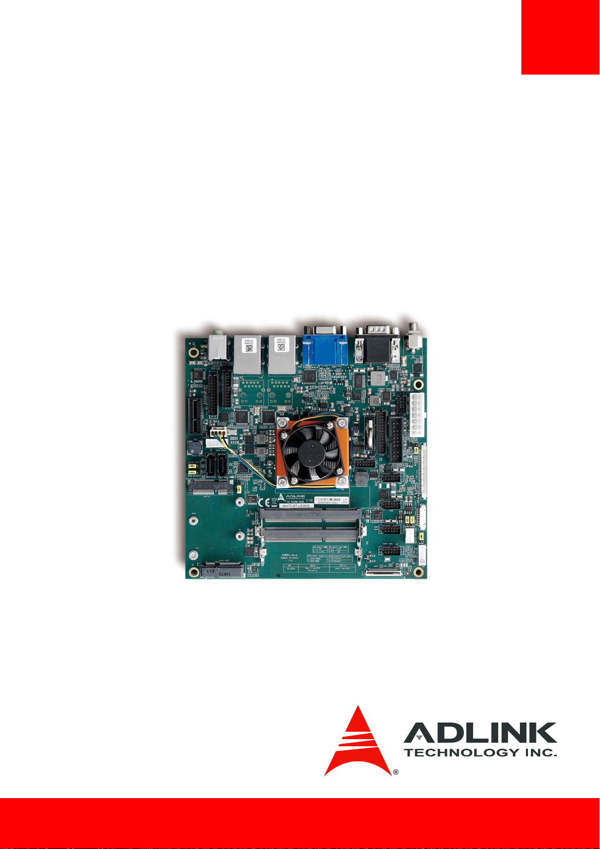
AmITX-BT-I
User’s Manual
Mini-ITX Embedded Motherboard with
4th Gen Intel® Atom™ Processor E3800
Manual Revision: 0.10
Revision Date: April 15, 2015
Part Number: 50-1X011-1000
Page 2

Revision History
Revision Description Date By
0.10 Preliminary release 2015-04-15 JC
Page 2 AmITX-BT-I
Page 3

Preface
Copyright 2015 ADLINK Technology, Inc.
This document contains proprietary information protected by copyright. All rights are reserved. No part of this manual may be reproduced by
any mechanical, electronic, or other means in any form without prior written permission of the manufacturer.
Disclaimer
The information in this document is subject to change without prior notice in order to improve reliability, design, and function and does not
represent a commitment on the part of the manufacturer. In no event will the manufacturer be liable for direct, indirect, special, incidental, or
consequential damages arising out of the use or inability to use the product or documentation, even if advised of the possibility of such
damages.
Environmental Responsibility
ADLINK is committed to fulfill its social responsibility to global environmental preservation through compliance with the European Union's
Restriction of Hazardous Substances (RoHS) directive and Waste Electrical and Electronic Equipment (WEEE) directive. Environmental
protection is a top priority for ADLINK. We have enforced measures to ensure that our products, manufacturing processes, components, and
raw materials have as little impact on the environment as possible. When products are at their end of life, our customers are encouraged to
dispose of them in accordance with the product disposal and/or recovery programs prescribed by their nation or company.
AmITX-BT-I is a RoHS compliant and leadfree product
Trademarks
Product names mentioned herein are used for identification purposes only and may be trademarks and/or registered trademarks of their
respective companies.
AmITX-BT-I Page 3
Page 4

Table of Contents
Revision History ............................................................................................................ 2
Preface............................................................................................................................ 3
1. Introduction .......................................................................................................... 7
1.1. Packing List ............................................................................................................................7
1.2. Optional Accessories .............................................................................................................7
2. Specifications........................................................................................................ 8
2.1. Core System...........................................................................................................................8
2.2. Rear I/O Connectors ..............................................................................................................8
2.3. Internal Headers and Connectors..........................................................................................8
2.4. Form Factor ...........................................................................................................................9
2.5. SEMA Board Controller..........................................................................................................9
2.6. Debug Header........................................................................................................................9
2.7. Video......................................................................................................................................9
2.8. Audio......................................................................................................................................9
2.9. LAN.........................................................................................................................................9
2.10. Power Specificatio .................................................................................................................9
2.11. Operating Temperatures .................................................................................................... 10
2.12. Environmental .................................................................................................................... 10
2.13. Operating Systems.............................................................................................................. 10
2.14. Power Consumption ........................................................................................................... 10
2.15. Functional Diagram............................................................................................................. 12
3. Mechanical Layout .............................................................................................
3.1. Connector Locations ........................................................................................................... 13
3.2. Mechanical Dimensions...................................................................................................... 14
3.3. Thermal Solutions............................................................................................................... 16
13
4. Connectors and Jumpers ................................................................................... 17
4.1. Rear IO Connectors............................................................................................................. 17
4.1.1. DC Power Inlet...................................................................................................................................17
4.1.2. Serial COM Ports (COM1, COM2) ......................................................................................................18
4.1.3. VGA Connector (VGA)........................................................................................................................19
4.1.4. HDMI Connector................................................................................................................. ...............19
4.1.5. Ethernet Connectors (LAN1, LAN2) ...................................................................................................20
4.1.6. USB 3.0 Connectors (USB1-4) ............................................................................................................20
4.1.7. Audio Connectors (Line-out, Mic-in) .................................................................................................21
Page 4 AmITX-BT-I
Page 5

4.2. Internal Connectors ............................................................................................................ 21
4.2.1. ATX Power Connector (ATX_PWR, proprietary) ................................................................................21
4.2.2. SATA Connectors (SATA1, SATA2) .....................................................................................................22
4.2.3. SATA Power Connector (ST_PWR).....................................................................................................22
4.2.4. USB Header........................................................................................................................................23
4.2.5. PS/2 Keyboard and Mouse Connector ..............................................................................................24
4.2.6. Internal Audio Connector ..................................................................................................................24
4.2.7. CPU Fan and System Fan Connectors................................................................................................25
4.2.8. Serial COM Port Connectors..............................................................................................................25
4.2.9. LVDS Connector.................................................................................................................................27
4.2.10. LVDS Auxiliary Connector ................................................................................................................28
4.2.11. Front Panel Connector.....................................................................................................................29
4.2.12. Feature Connector...........................................................................................................................30
4.2.13. SPI Header .......................................................................................................................................31
4.2.14. DB40 Debug Board Connector.........................................................................................................32
4.3. Jumper and Switch Settings................................................................................................ 33
4.3.1. ATX/AT Mode Jumper Selection (JPY1) .............................................................................................33
4.3.2. Clear CMOS and BIOS Default (JP5)...................................................................................................33
4.3.3. Reset BIOS Defaults (JP6) ..................................................................................................................33
4.3.4. SATA2/mSATA Select (JP1) ................................................................................................................33
4.3.5. LVDS Backlight Power Jumper Selection (JP2)...................................................................................34
4.3.6. LVDS Panel Power Jumper Selection (JP3) ........................................................................................34
4.3.7. LVDS Backlight Enable Jumper Selection (JP4) ..................................................................................34
4.3.8. Serial Port Mode Switch Setting (SW14, SW10, SW11).....................................................................35
4.3.9. BIOS Switch Setting (SW1).................................................................................................................35
4.4. Onboard Connector Information........................................................................................ 36
5. Driver Installation............................................................................................... 37
6. Smart Embedded Management Agent (SEMA) .............................................. 38
6.1. Board Specific SEMA Functions .......................................................................................... 38
6.1.1. Voltages.............................................................................................................................................38
6.1.2. Main Current .....................................................................................................................................39
6.1.3. BMC Status ........................................................................................................................................39
6.1.4. Exception Codes ................................................................................................................................39
6.1.5. BMC Flags ..........................................................................................................................................40
7. System Resources...............................................................................................
41
7.1. System Memory Map ......................................................................................................... 41
7.2. I/O Map............................................................................................................................... 41
7.2.1. I/O Map .............................................................................................................................................41
AmITX-BT-I Page 5
Page 6

7.2.2. IRQ Lines PIC mode............................................................................................................................42
7.2.3. IRQ Lines APIC mode .........................................................................................................................43
7.3. PCI Configuration Space Map ............................................................................................. 44
7.4. PCI Interrupt Routing Map.................................................................................................. 45
7.5. SMBus Slave Address.......................................................................................................... 45
Safety Instructions ...................................................................................................... 46
Getting Service ............................................................................................................ 47
Page 6 AmITX-BT-I
Page 7
1. Introduction
The AmITX-BT-I is a Mini-ITX motherboard supporting the Intel® Atom™ processor E3800 Series and Intel® Celeron® processor system-onchip (SoC). The AmITX-BT-I is specifically designed for customers who need high-level processing and graphics performance with low
power consumption in a long product life solution.
®
The Intel
to provide excellent overall performance. Integrated Intel® Gen7 HD Graphics includes features such as OpenGL 3.1, DirectX 11, OpenCL
1.1 and support for H.264, MPEG2, VC1, VP8 hardware decode. Graphics outputs include VGA, DDI ports supporting HDMI and optional
dual-channel 18/24-bit LVDS. The AmITX-BT-I has dual stacked SODIMM sockets for up to 8 GB non-ECC type DDR3L memory.
Atom™ processor E3800 and Intel® Celeron® processor support non-ECC type DDR3L dual-channel memory at 1066/1333 MHz
The AmITX-BT-I features dual Gigabit Ethernet port, USB 3.0 ports and USB 2.0 ports, and SATA 3 Gb/s ports. Support is provided for
2
SMBus and I
C. The module is equipped with SPI AMI EFI BIOS, supporting embedded features such as hardware monitor and watchdog
timer.
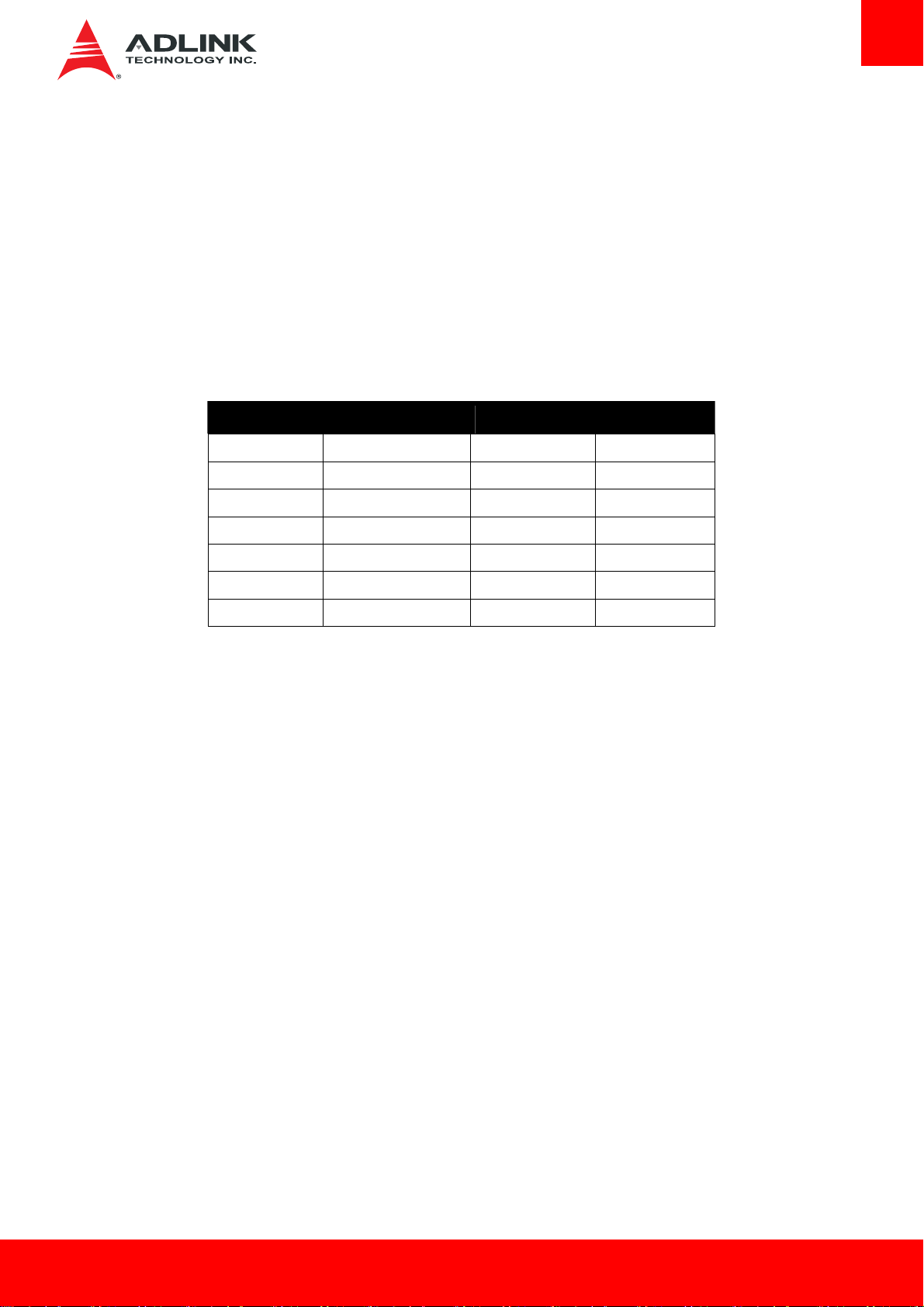
CPU Intel Bay Trail SoC Core Speed Total Design Power
AmITX-BT-I-E3845 Atom™ E3845 (4 cores) 1.91 GHz 10W
AmITX-BT-I-E3827 Atom™ E3827 (2 cores) 1.75 GHz 8W
AmITX-BT-I-E3826 Atom™ E3826 (2 cores) 1.46 GHz 7W
AmITX-BT-I-E3825 Atom™ E3825 (2 cores) 1.33 GHz 6W
AmITX-BT-I-E3815 Atom™ E3815 (1 core) 1.46 GHz 5W
AmITX-BT-I- N2930 Celeron® N2930 (4 cores) 1.83/2.16 (Burst) GHz 7.5W
AmITX-BT-I-J1900 Celeron® J1900 (4 cores) 2.0/2.42 (Burst) GHz 10W
Latest revision of the datasheet, user’s manual, BIOS, drivers, and board support packages, can be downloaded from the product webpage:
www.adlinktech.com/PD/web/PD_detail.php?cKind=&pid=1444.
1.1. Packing List
• AmITX-BT-I motherboard
• ATX/AT power cable (P/N: 30-20872-1000)
• SATA dual power cable (P/N: 30-20875-0000)
• SATA cable (P/N: 30-10057-0600)
• Rear I/O shield (P/N: 34-25313-0000)
• Standard packing box
1.2. Optional Accessories
• COM port cable, 1 Port (P/N: 34-25313-0000)
• PS/2 KB/MS cable (P/N: 30-20873-0000)
• USB 2.0 cable, 2 Ports (P/N: 30-20874-1000)
AmITX-BT-I Page 7
Page 8

2. Specifications
2.1. Core System
¾ CPU: Single, dual or quad-core Intel® Atom™ or Celeron® Processor
• Atom™ E3845 1.91 GHz 542/792 (Turbo) 10W (4C/1333)
• Atom™ E3827 1.75 GHz 542/792 (Turbo) 8W (2C/1333)
• Atom™ E3826 1.46 GHz 533/667 (Turbo) 7W (2C/1066)
• Atom™ E3825 1.33 GHz 533 (No Turbo) 6W (2C/1066)
• Atom™ E3815 1.46 GHz 400 (No Turbo) 5W (1C/1066)
• Celeron® N2930 1.83/2.16 (Burst) GHz, 313/854 (Turbo) 7.5W (4C/1333)
• Celeron® J1900 2.0/2.42 (Burst) GHz, 688/854 (Turbo) 10W (4C/1333)
Supports: Single, dual or quad Out-of-Order Execution (OOE) processor cores, Intel® VT-x, Intel® SSE4.1 and SSE4.2, Intel® 64
architecture, IA 32-bit, PCLMULQDQ Instruction, DRNG, Intel® Thermal Monitor (TM1 & TM2)
Note: Availability of features dependent on processor SKU.
¾ Cache: Primary 32 kB, 8-way L1 instruction cache and 24 kB, 6-way L1 write-back data cache
¾ Memory: Dual channel non-ECC 1066/1333 MHz DDR3L memory up to 8GB in dual stacked SODIMM sockets
¾ Embedded BIOS: AMI EFI in 8MB SPI BIOS
2.2. Rear I/O Connectors
¾ Display: VGA and HDMI
¾ LAN: Dual GbE RJ-45
¾ USB: 4x USB 3.0
¾ Serial: 1x RS-232 (COM1 supports console redirection), 1x RS-232/422/485
¾ Aduio: Line-Out, Mic-In
¾ Power: Screw Jack for 12V DC-in
2.3. Internal Headers and Connectors
¾ PCIe x1
¾ 2x Mini-PCIe: one PCIe+USB & one mSATA+USB
¾ USB: 2x USB 2.0 via onboard header, 2x USB 2.0 via front panel connector
¾ SATA: 2x SATA 3Gb/s (SATA0, SATA1)
¾ SATA Power Connector
¾ eMMC: Soldered on Module Bootable eMMC Flash Storage 8 to 64 GB (optional)
¾ Serial: 2x RS-232 headers, 2x RS-232/422/485 headers with 5V power (12V by BOM option)
¾ LVDS: Supports non-EDID type LCD panels only
¾ SIM Card Holder:
¾ Front Panel Header
¾ Audio Header
¾ Feature Connector Header
¾ PS/2 KB/MS Connector
¾ TPM Header
¾ SPI Header
¾ ATX Power Connector
Page 8 AmITX-BT-I
Page 9

2.4. Form Factor
¾ Mini-ITX: 170mm x 170mm
2.5. SEMA Board Controller
¾ ADLINK Smart Embedded Management Agent (SEMA)
• Voltage/Current monitoring
• Power sequence debug support
• AT/ATX mode control
• Logistics and Forensic information
• Flat Panel Control
• General Purpose I2C
• Failsafe BIOS (dual BIOS )
• Watchdog Timer and Fan Control
2.6. Debug Header
¾ 40-pin Multipurpose Flat Cable Connector:, used in combination with DB-40 debug module providing BIOS POST code LED, BMC
access, SPI BIOS flashing, Power Testpoints, Debug LEDs
2.7. Video
¾ GPU Feature Support: 7th generation graphics Intel core architecture with four execution units supporting two independent displays
• 3D graphics hardware acceleration
• Support for DirectX11, OCL 1.1, OGL ES Halt/2.0/1.1, OGL 3.2
• Video decode hardware acceleration including support for H.264, MPEG2, VC-1, WMV and VP8 formats
• Video encode hardware acceleration including support for H.264, MPEG2 and MVC formatsPlayback of Blu-ray disc S3D content
using HDMI (1.4a spec compliant with 3D)
Note: Availability of features may vary between operating systems.
¾ Display Interface support
• VGA: Analog VGA supporting resolutions up to 2560x1600 x24bpp at 60 Hz
• HDMI: HDMI 1.3a
• LVDS: Supports non-EDID type LCD panels only, Single/Dual Channel 18 and 24-bit, supports 1920 x 1200 at 60 Hz resolution in
dual LVDS bus mode
2.8. Audio
¾ Integrated: Intel® HD Audio integrated in SOC
¾ Audio Codec: ALC886
2.9. LAN
¾ Intel MAC/PHY: Intel® i211AT (MAC/PHY) Ethernet controller
¾ Interface: 10/100/1000 GbE connection
2.10. Power Specifica tio
¾ Power Modes: AT and ATX mode (AT mode start controlled by BMC)
¾ Standard Voltage Input: ATX = 12V ±5%, 5Vsb ±5% or AT = 12V ±5%
¾ Power Management: ACPI 4.0 compliant
¾ Power States: Supports C1-C6, S0, S1, S4, S3, S5, (Wake-on-USB S3/S4, WoL S3/S4/S5)
AmITX-BT-I Page 9
Page 10
2.11. Operating Temperatures
¾ Standard: 0°C to 60°C
¾ Extreme Rugged™: -40°C to 85°C* (optional)
*Note: Intel® Atom™ E3800 Series processors only
2.12. Environmental
¾ Humidity: 10-90% RH operating, non-condensing
5-95% RH storage (and operating with conformal coating)
¾ Shock and Vibration: IEC 60068-2-64 and IEC-60068-2-27
MIL-STD-202F, Method 213B, Table 213-I, Condition A and Method 214A, Table 214-I, Condition D
¾ HALT: Thermal Stress, Vibration Stress, Thermal Shock and Combined Test
2.13. Operating Systems
¾ Standard Support: Windows 7/8 32/64-bit, Linux 32/64-bit
¾ Extended Support (BSP): WES7, WE8S, WEC7, Linux, VxWorks
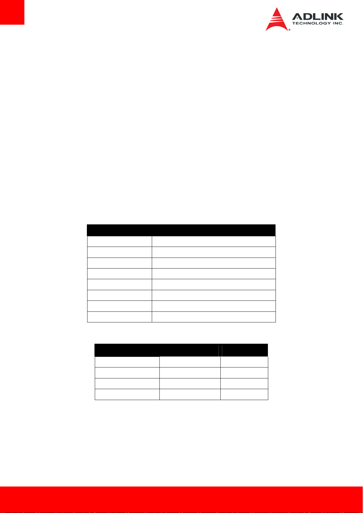
2.14. Power Consumption
Processor Intel® Atom™ Processor E3845 (2M Cache, 1.91 GHz)
Memory Slot1 Transcend 8G 2Rx8 DDR3L 1600 SODIMM
Memory Slot2 Transcend 8G 2Rx8 DDR3L 1600 SODIMM
Graphics Intel® HD Graphics
Storage WD WD3200BUDT 320GB, 2.5" SATA 3Gb/s HDD
Monitor BenQ GW2255
Power Supply FSP FSP350-60PFG 350W ATX
Video Resolution 1920 x 1080 @32-bit
¾ Intel® Atom™ processor E3845 @ 1.91 GHz
Power State Current(A) / Voltage (V) Power (W)
Windows 7 (Idle) 0.61/11.82 7.2102
Windows 7 (Typical) 0.92/11.78 10.8376
System Configuration
Windows 7 (Max loading) 1.08/11.77 12.7116
S3 0.3/5.02 1.506
Page 10 AmITX-BT-I
Page 11
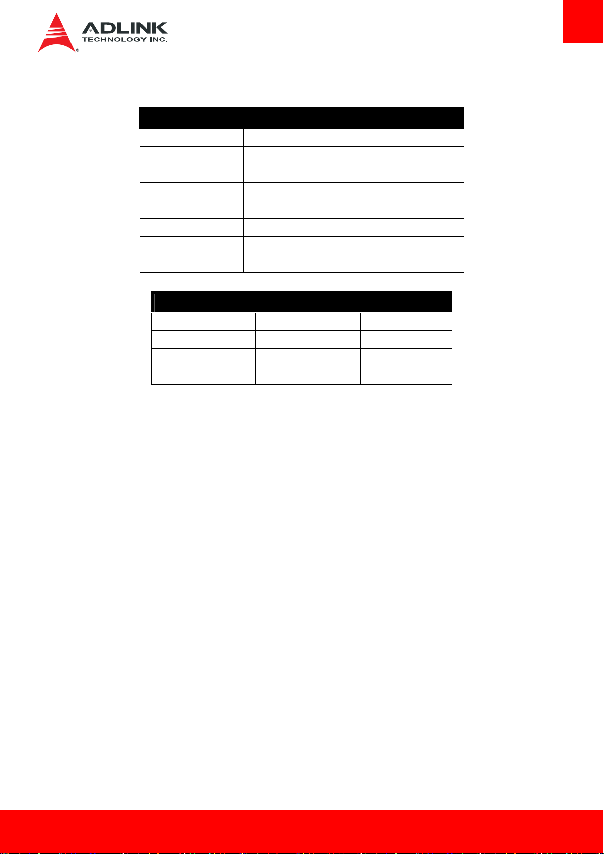
¾ Intel Celeron CPU N2930 @ 1.83GHz
Processor Intel® Celeron® Processor N2930 (2M Cache, 1.83 GHz)
Memory Slot1 Transcend 8G 2Rx8 DDR3L 1600 SODIMM
Memory Slot2 Transcend 8G 2Rx8 DDR3L 1600 SODIMM
Graphics Intel® HD Graphics
HDD WD WD3200BUDT 320GB, 2.5" SATA II HD
Monitor Hanns.G HZ222
Power Supply FSP FSP600-80PSA 600W ATX
Video Resolution 1680 x 1050 @32-bit
Power State Current(A) / Voltage (V) Power (W)
System Configurations
Windows 7 (Idle) 0.58/12.03 6.9774
Windows 7 (Typical) 0.89/12.03 10.7067
Windows 7 (Max loading) 1.02/12.03 12.2706
S3 0.25/5.00 1.25
AmITX-BT-I Page 11
Page 12
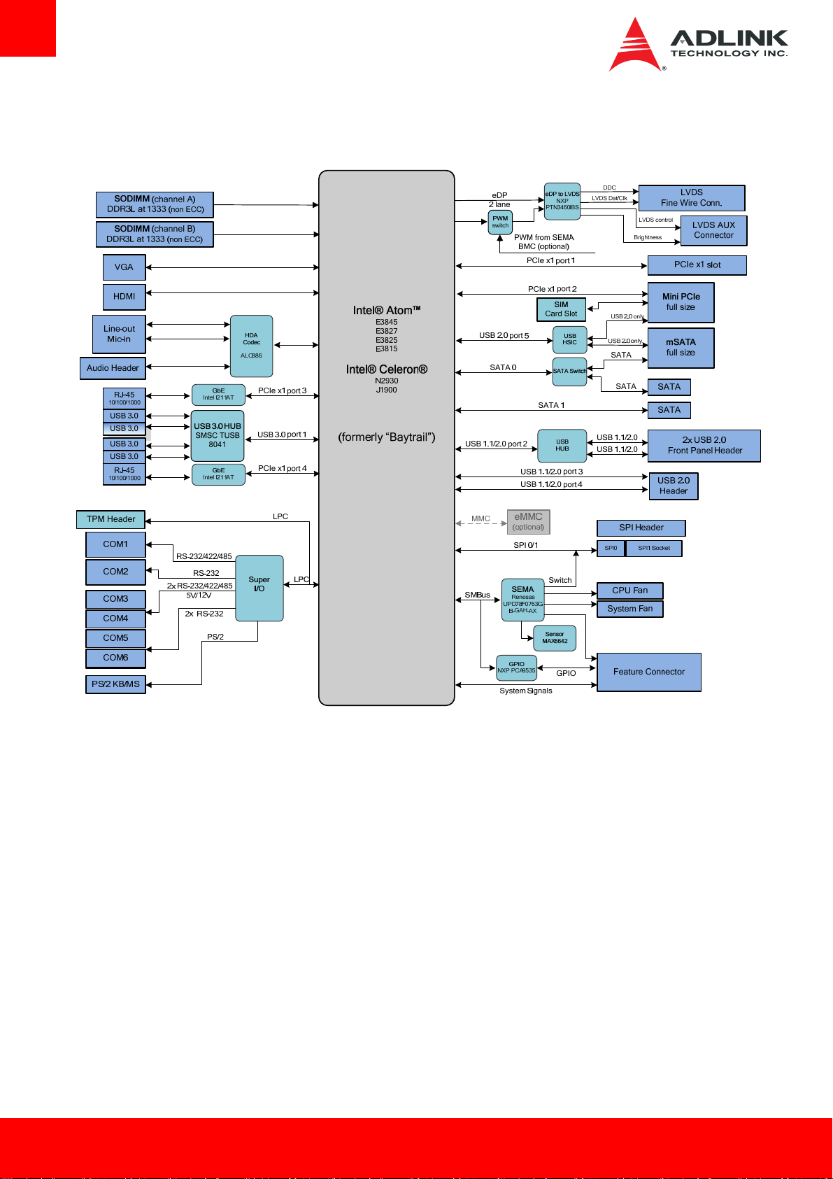
2.15. Functional Diagram
Page 12 AmITX-BT-I
Page 13

3. Mechanical Layout
3.1. Connector Locations
Front Panel
Connector
Audio Connector
PCIe x1
SATA Power
2x SATA 3Gb/s
mSATA Slot
12V DC-in
COM1
COM2
VGA
HDMI
LAN
USB 3.0
LAN
USB 3.0
Line-out
Mic-in
12V DC-in
USB Header
ATX Power
Feature
Connector
TPM Header
SPI Header
LVDS
Stacked SODIMMs
Mini PCIe
4x COM Ports
PS/2 KB/MS
DB40 Connector
SIM Card Slot
AmITX-BT-I Page 13
Page 14
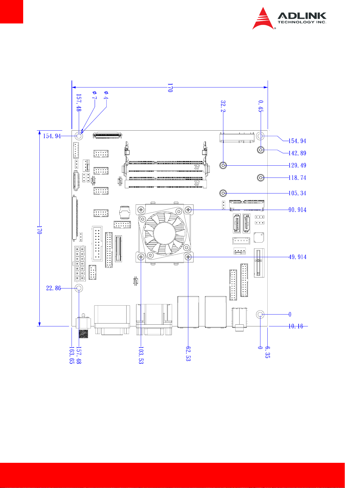
3.2. Mechanical Dimensions
Top View
Dimensions: mm
All Φ tolerances ±0.05mm
Other tolerances ±0.2mm
Page 14 AmITX-BT-I
Page 15
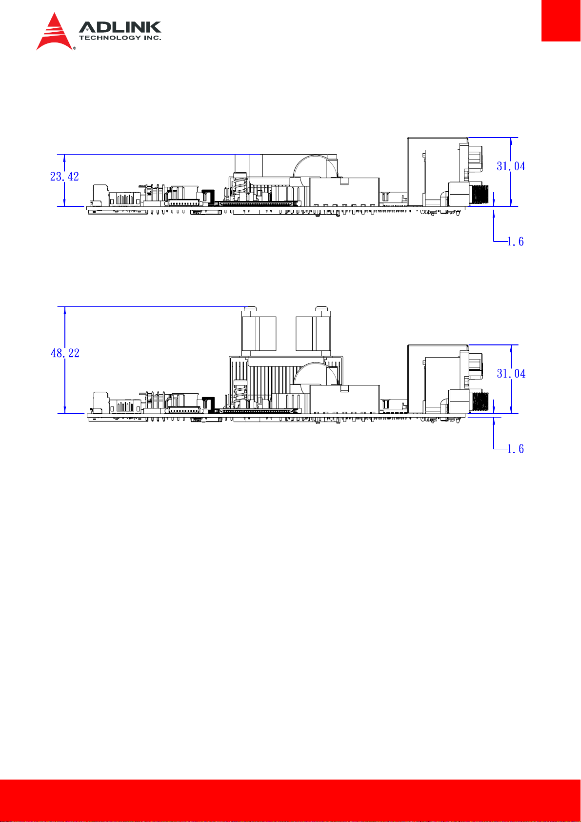
Side View
With AmITX-BT_4010- CJ Cooler (Standard Temp.: 0°C to +60°C)
With AmITX-BT_4020-CJ Cooler (Extreme Rugged™: -40°C to +85°C, Intel® Atom™ E38xx only)
Dimensions: mm
All tolerances ±0.2mm
AmITX-BT-I Page 15
Page 16

3.3. Thermal Solutions
AmITX-BT_4010-RG Cooler-with Fan
Standard Temp.: 0°C to 60°C
P/N: 32-20493-1000
AmITX-BT_4010- CJ Cooler-with Fan
Standard Temp.: 0°C to 60°C
P/N: 32-20493-0000
AmITX-BT_CU-CJ Passive Heatsink
Standard Temp.: 0°C to 60°C
P/N: 32-20510-0000
AmITX-BT_4020-CJ Cooler with Fan
Extreme Rugged™: -40°C to +85°C (Atom™ E38xx only)
P/N: 32-20494-0000
Page 16 AmITX-BT-I
Page 17

y
g
4. Connectors and Jumpers
See 3.1 Connector Locations on page 13 for connector locations.
4.1. Rear IO Connectors
4.1.1. DC Power Inlet
The AmITX-BT-I supports a screw-type external 12V DC-in power connector. Maximum current draw is 10A.
Note: Either the DC Power Inlet or
JACK1
PWR-JACK_P1
the internal ATX Power Connector (ATX_PWR) must be used to supply the motherboard with +12V ±5%.
1
VCC
3
GND2
2
GND1
Caution:
Hot-plugging the power supply is not supported. Doing so may damage the board.
Only connect ONE power supply to the board. Connecting power to both the 12V
dama
DC-inlet and the internal ATX Power Connector ma
e the board.
AmITX-BT-I Page 17
Page 18

4.1.2. Serial COM Ports (COM1, COM2)
COM1: Supports RS-232/422/485
COM2: Supports RS-232 only
Pin # RS-232 RS-422 RS-485
1 DCD, Data Carrier Detect TX- RTX-
2 RXD, Receive Data TX+ RTX+
3 TXD, Transmit Data RX+ N/A
4 DTR, Data Terminal Ready RX- N/A
5 GND N/A N/A
6 DSR, Data Set Ready N/A N/A
7 RTS, Request To Send N/A N/A
8 CTS, Clear To Send N/A N/A
9 RI, Ring Indicator N/A N/A
SW14: Switch for mode selection of COM1 (default RS-232).
SW14
Page 18 AmITX-BT-I
Page 19

4.1.3. VGA Connector (VGA)
Signal Pin # Pin # Signal
Red 1 2 Green
Blue 3 4 VCC pull-up
GND 5 6 GND
GND 7 8 GND
VCC 9 10 GND
VCC pull-up 11 12 DDC2B DATA
HSYNC 13 14 VSYNC
DDC2B CLK 15
4.1.4. HDMI Connector
Pin # Signal Pin # Signal
1 TMDS Data2+ 2 TMDS Data2 Shield
3 TMDS Data2– 4 TMDS Data1+
5 TMDS Data1 Shield 6 TMDS Data1–
7 TMDS Data0+ 8 TMDS Data0 Shield
9 TMDS Data0– 10 TMDS Clock+
11 TMDS Clock Shield 12 TMDS Clock–
13 CEC 14 Reserved
15 SCL 16 SDA
17 DDC/CEC Ground 18 +5 V Power
19 Hot Plug Detect
AmITX-BT-I Page 19
Page 20

4.1.5. Ethernet Connectors (LAN1, LAN2)
Pin # 10BASE-T/100BASE-TX 1000BASE-T
1 TX+ LAN_MDI0+
2 TX- LAN_MDI0-
3 RX+ LAN_MDI1+
4 -- LAN_MDI2+
5 -- LAN_MDI2-
6 RX- LAN_MDI1-
7 -- LAN_MDI3+
8 -- LAN_MDI3-
LED1 (Speed) LED2 (Link/Activity)
Status Description Status Description
Off 10 Mb connection Off No Link
Green 100 Mb connection Orange Linked
Orange 1 Gb connection Blinking Data Activity
4.1.6. USB 3.0 Connectors (USB1-4)
Pin # Signal
1 USB3.0_P5VA
2 USB2_CMAN
3 USB2_CMAP
4 GND
5 USB3A_CMRXN
6 USB3A_CMRXP
7 GND
8 USB3A_CMTXN
9 USB3A_CMTXP
Page 20 AmITX-BT-I
Page 21

4.1.7. Audio Connectors (Line-out, Mic-in)
Jack Contact Signal
Tip FRONT-OUT-L
Line-out
Mic-in
Ring FRONT-OUT-R
Sleeve GND
Tip MIC1-L
Ring MIC1-R
Sleeve GND
Note: Shared with onboard Audio Header; un-amplified codec output.
4.2. Internal Connectors
4.2.1. ATX Power Connector (ATX_PWR, proprietary)
AmITX-BT-I supports a proprietary internal ATX Power Connector (ATX_PWR). An adapter cable is provided for connection to a standard
ATX power supply.
Note: Either the DC Power Inlet or
the internal ATX Power Connector (ATX_PWR) must be used to supply the motherboard with +12V ±5%.
Pin # Signal Pin # Signal
1 SB5V 8 P_OK
2 GND 9 PS_ON#
3 GND 10 +12V
4 GND 11 +12V
5 GND 12 +12V
6 GND 13 +12V
7 3.3V 14 +5V
14
1
Only connect ONE power supply to the board. Connecting power to both the 12V DC-inlet and the internal ATX Power
CAUTION
Connector may damage the board.
AmITX-BT-I Page 21
Page 22

ATX Adapter Cable: ADLINK Part. No. 30-20872-1000 (length 250 mm)
Motherboard
ATX Power
Connector
(ATX_PWR)
4.2.2. SATA Connectors (S ATA1, SATA2)
ATX Power
Supply
Two SATA ports are available on the AmITX-BT-I and support SATA Gen2 (3.0/1.5Gb/s).
Note: If mSATA is installed, SATA2 is disabled. See
4.3.4 SATA2/mSATA Select (JP1).
Pin # Signal
1 GND
2 TXP
3 TXN
4 GND
5 RXN
6 RXP
7 GND
4.2.3. SATA Power Connector (ST_PWR)
Pin # Signal
1 12V
5 4 3 2 1
SATA Power
SATA2 SATA1
2 GND
3 5V
4 GND
5 3.3V
Page 22 AmITX-BT-I
Page 23

ower
SATA Power Cable: ADLINK Part. No.: 30-20875-0000 (length 200 mm)
HDD/SSD
P
4.2.4. USB Header
HDD/SSD
Power
Motherboard
SATA Power
Connector
5V/SB5V: 5V supplies for external devices. SB5V is supplied during power down to allow wakeup on USB device activity during S3~S4 state.
P5V_USB2
2
4
85USB2_P3_DN_R
6
85USB2_P3_DP_R
8
10
85USB2_P2_DN_R
85USB2_P2_DP_R
P5V_USB2
1
3
5
7
CN35
BH_10_S2mm_N9
Pin # Signal Pin # Signal
P5V_USB
1
P2_DN_R-
3
P2_DP_R
5
GND
7
KEY
9
2
4
6
8
10
P5V_USB
P3_DN_R
P3_DP_R
GND
GND
1
10
USB Cable (optional):
USB 2.0 Header to 2x Female Type-A Cable (length 200mm), P/N: 30-20874-1000
AmITX-BT-I Page 23
Page 24

4.2.5. PS/2 Keyboard and Mouse Connector
6 pin 2.0 pitch standard wafer connector. No support for PS/2 KB/MS wake function
KB/MS Cable (optional):
PS/2 KB/MS Cable (length 400mm), P/N: 30-20873-0000
Pin # Signal
1 MSCLK
2 V5S_S3
3 MSDATA
4 GND
5 KBDATA
6 KBCLK
1
2
3
4
5
6
4.2.6. Internal Audio Connector
2x13-pin 2.0 pitch standard wafer connector.
Note: Signals shared with Audio Connector on Rear I/O.
Signal Pin # Pin # Signal
LFE-OUT 1 2 CEN-OUT
AAGND 3 4 AAGND
FRONT-OUT-L 5 6 FRONT-OUT-R
AAGND 7 8 AAGND
REAR-OUT-L 9 10 REAR-OUT-R
SIDE-OUT-L 11 12 SIDE-OUT-R
AAGND 13 14 AAGND
MIC1-L 15 16 MIC1-R
AAGND 17 18 AAGND
LINE1-L 19 20 LINE1-R
1 2
MUTE 21 22 AAGND
GND 23 24 NC
SPDIF-OUT 25 26 GND
Page 24 AmITX-BT-I
Page 25

4.2.7. CPU Fan and System Fan Connectors
Pin 3 and 4 are connected (monitored and managed) by SEMA controller.
Pin # Signal
1 GND
2 Fan Power (+12V)
3 Fan Sense
4 Fan Speed Control
4.2.8. Serial COM Port Connectors
Four internal Serial Ports (COM3-6)
Serial Port Functions
COM3 Supports RS-232 / RS-422 / RS-485,
5V/12V power support by BOM option
(default 5V).
SW10: Switch for mode selection of COM3
(default RS-232).
COM4 Supports RS-232 / RS-422 / RS-485,
5V/12V power support by BOM option
(default 5V).
SW11: Switch for mode selection of COM4
(default RS-232).
COM5 Supports RS-232 only, 5V/12V power
support by BOM option (default 5V).
CPU
Fan
COM3
SW10 SW11
COM4
COM5
COM6
System
Fan
COM6 Supports RS-232 only, 5V/12V power
support by BOM option (default 5V).
RS-232
Pin # Signal Pin # Signal
1 DCD 2 DSR
3 RxD 4 RTS
5 TxD 6 CTS
7 DTR 8 RI
9 GND 10 5V / 12V
AmITX-BT-I Page 25
Page 26

RS-422 (COM3-4 only)
RS-485 (COM3-4 only)
Pin # Signal Pin # Signal
1 Tx- 2 Tx+
3 Rx+ 4 Rx-
5 6
7 8
9 GND 10 5V / 12V
Pin # Signal Pin # Signal
1 Tx/Rx- 2 Tx/Rx+
3 4
5 6
7 8
9 GND 10 5V / 12V
SW10/SW11 (RS-422/485 Mode Select)
RS-232 (default) RS-422 RS-485
1 ON* ON OFF
2 OFF* ON ON
See Section 4.3.8 Serial Port Mode Switch Setting (SW14, SW10, SW11)
COM Cable (optional):
COM Port Cable (length 250mm), P/N: 30-20876-0000
Page 26 AmITX-BT-I
Page 27

4.2.9. LVDS Connector
FFC Connector : Female, 30pin, 1mm pitch. (JAE, FI-X30SSLA-HF)
Supports non-EDID type LCD panels.
Signal Description
LVDS A0..A3 LVDS A Channel data
LVDS ACLK LVDS A Channel clock
LVDS B0..B3 LVDS B Channel data
LVDS BCLK LVDS B Channel clock
VDD ENABLE Output Display Enable.
LCDVCC VCC supply to the display. Power-on/off
sequencing depending on selected display type
in the BIOS Setup.
Switchable by jumper either 3.3V (default) or 5V.
Maximum load is 1A total for both voltages.
DDC CLK DDC Channel Clock
DDC DAT DDC Channel Data
Note Type Signal Pin # Pin # Signal Type Note
LVDS LVDS A0- 1 16 LVDS B1+ LVDS
LVDS LVDS A0+ 2 17 POWER GND PWR Max. 0.5A
LVDS LVDS A1- 3 18 LVDS B2- LVDS
LVDS LVDS A1+ 4 19 LVDS B2+ LVDS
LVDS LVDS A2- 5 20 LVDS BCLK- LVDS
LVDS LVDS A2+ 6 21 LVDS BCLK+ LVDS
Max. 0.5A PWR POWER GND 7 22 LVDS B3- LVDS
LVDS LVDS ACLK- 8 23 LVDS B3+ LVDS
LVDS LVDS ACLK+ 9 24 POWER GND PWR Max. 0.5A
LVDS LVDS A3- 10 25 DDC DATA OT PU 2K2Ω, 3.3V
LVDS LVDS A3+ 11 26 VDD ENABLE OT 3.3V level
LVDS LVDS B0- 12 27 DDC CLK OT PU 2K2Ω, 3.3V
LVDS LVDS B0+ 13 28 LCDVCC PWR Max 0.5A
Max. 0.5A PWR POWER GND 14 29 LCDVCC PWR Max 0.5A
LVDS LVDS B1- 15 30 LCDVCC PWR Max 0.5A
AmITX-BT-I Page 27
Page 28

4.2.10. LVDS Auxiliary Connector
Wafer 1x10 pin: 1.25 mm pitch (MOLEX, 53261-1071)
Pin Type Signal Note
1 OT BKLT_EN# 3.3V level
2 PWR GND Max. 0.5A
3 PWR GND Max. 0.5A
4 PWR BKLT_PWR Max. 0.5A
5 PWR BKLT_PWR Max. 0.5A
6 PWR BKLT_PWR Max. 0.5A
7 PWR BKLT_PWR Max. 0.5A
8 PWR GND Max. 0.5A
9 PWR GND Max. 0.5A
10 OT BKLT_CTL 3.3V level
Signal Description
BKLT_EN# Backlight Enable signal (active low)
BKLT_PWR Backlight Power switchable by jumper either 5V (default) or 12V. Maximum 1A per pin for both voltages
BKLT_CTL Backlight control, PWM signal to implement voltage in the range 0-3.3V
See Chapter
(JP3) settings.
Optional to invert this signal to active high BKLT_EN (by jumper)
4.3 Jumper and Switch Settings for Backlight Power Selection (JP2), Panel Power Selection (JP3), and Panel Power Selection
Page 28 AmITX-BT-I
Page 29

4.2.11. Front Panel Connector
2x12-pin 2.0 pitch standard wafer connector
The front panel connector of AmITX-BT-I provides two USB2.0 header, Audio MIC-In / Line-Out, ATX power switch, Reset, HDD LED, and
SUS LED (System Power LED).
Pin # Signal Ioh/ Iol Type Note Pin # Signal Type Ioh/ Iol Note
1 USB6/7_5V - PWR 1 2 USB6/7_5V PWR - 1
3 USB6- - 4 USB7- -
5 USB6+ - 6 USB7+ -
7 GND - PWR 8 GND PWR -
9 Mute - Mute 10 LINE2-L -
11 +5V - PWR 2 12 +5V PWR - 2
13 SATA_LED# 25/25mA O 14 SUS_LED O 7mA 3
15 GND - PWR 16 PWRBTN_IN# I
1 2
17 RSTIN# - I 18 GND PWR -
19 SB3V3 - PWR 20 LINE2-R -
21 AGND - PWR 22 AGND PWR -
23 MIC2-L - AI 24 MIC2-R AI -
Note 1: 5V/SB5V: 5V supplies for external devices. SB5V is supplied during power down to allow wakeup on USB device activity during
S3~S4 state.
Note 2: Maximum load is 1A.
Note 3: SUS_LED (System Power LED): Connect to the power status indicator on the chassis front panel. The LED is on when the
system is operating. The LED keeps blinking when the system is in S1/S3 sleep state. The LED is off when the system is in S4 sleep state
or powered off (S5).
AmITX-BT-I Page 29
Page 30

4.2.12. Feature Connector
2x13-pin 2.0 pitch standard wafer connector
2
The feature connector of AmITX-BT-I provides Case Open, I
Signal Description
TEMPS Analogue temp sensor, connect to analog input of BMC
EXT_BAT Connect to RTC power
CASE_OPEN# Any time case open occurred, system will notice/show case open alert in
POST when the next booting.
I2CC / I2CD Connect to BMC (I2C Master)
I2C SEMA
Pin # Signal Pull U/D Ioh/ Iol Type Note Pin # Signal Type Ioh/ Iol Pull U/D Note
C, SMBus, and GPIO(10pin).
1 CASE_OPEN# PU 2M - I 2 SMBC OT /4mA PU 10K 1
3 GND - - PWR 4 SMBD OT /4mA PU 10K 1
5 TEMPS - I 2 6 I2CC OT - PU 10K 1
7 EXT_BAT - PWR 8 I2CD OT - PU 10K 1
9 SB3V3 - - PWR 10 SB5V PWR - -
11 GND - - PWR 12 GND PWR - -
13 GPIO0 - PU10K3V3 IOT 14 GPIO1 IOT PU10K3V3
15 GPIO2 - PU10K3V3 IOT 16 GPIO3 IOT PU10K3V3
17 GPIO4 - PU10K3V3 IOT 18 GPIO5 IOT PU10K3V3
19 GPIO6 - PU10K3V3 IOT 20 GPIO7 IOT PU10K3V3
21 GPIO8 PU10K3V3 IOT 22 GPIO9 IOT PU10K3V3
23 GND - PWR 24 SUS_S3# O 25/25mA -
25 12V - - PWR 26 SUS_S4# O 25/25mA -
27 PWR_OK - 25/25mA O 28 SUS_S5# O 25/25mA -
Note 1: Pull-up to +3V3Dual (+3V3 or SB3V3).
Note 2: Input to SEMA.
1 2
Page 30 AmITX-BT-I
Page 31

4.2.13. SPI Header
2x6-pin 2.0 pitch standard wafer connector
Type Signal Pin # Pin # Signal Type
CLK 1 2 SB3V3 PWR
I CS0# 3 4 ADDIN IO
I CS1# 5 6 NC -
I MOSI 7 8 ISOLATE IO
O MISO 9 10 GND PWR
IO SPI_IO2_#WP 11 12 SPI_IO3_#HOLD IO
1 2
Signal Description
CLK Serial Clock
SB3V3 3.3V Standby Voltage power line. Normally output power, but when Motherboard is turned off then the on-board
SPI Flash can be 3.3V power sourced via this pin.
CS0# CS0# Chip Select 0, active low.
ADDIN ADDIN input signal must be NC.
MOSI Master Output, Slave Input
ISOLATE# The ISOLATE# input, active low, is normally NC, but must be connected to GND when loading SPI flash. Power
Supply to the Motherboard must be turned off when loading SPI flash. The pull up resistor is connected via diode
to 5VSB.
MISO Master Input, Slave Output
SPI_IO2_#WP SPI Data I/O: A bidirectional signal used to support the new Dual
IO Fast Read, Quad IO Fast Read and Quad Output Fast Read modes. This signal is not used in Dual Output
Fast Read mode.
SPI_IO3_#HOLD SPI Data I/O: A bidirectional signal used to support the new Dual
IO Fast Read, Quad IO Fast Read and Quad Output Fast Read modes. This signal is not used in Dual Output
Fast Read mode.
AmITX-BT-I Page 31
Page 32

4.2.14. DB40 Debug Board Connector
FPC Connector Type: FCI 59GF Flex 10042867
1 40
Pin Interface Signal Remark Pin Interface Signal Remark
1 VCC_SPI_IN SPI Power Input from flash tool to
SPI
Program
interface
2 GND 22 RXD6
3 SPI_BIOS_CS0# 23 FUMD0
4 SPI_BIOS_CS1# 24 RESET_IN#
5 SPI_BIOS_MISO 25 DATA
6 SPI_BIOS_MOSI 26 CLK
7
8 3V3_LPC System power 3.3V provide from
LPC Bus
9 GND 29 PWRBTN#
10 CB_RESET# Platform Reset 30 SYS_RESET#
11 RST# 31 CB_RESET#
12 CLK33_LPC 32 CB_PWROK
13 LPC_FRAME# 33 SUS_S3#
14 LPC_AD3 34 SUS_S4#
15 LPC_AD2 35
16 LPC_AD1 always power 3.3V provide from
17
18
BMC
Program
interface
19 3.3V_BMC always power 3.3V provide from
20
SPI_BIOS_CLK 27 OCD0A Include a jumper to
LPC_AD0 37 SEL_BIOS Connect to Jumper for
3.3V_BMC always power 3.3V provide from
GND 40 Reserved
module. HW need add MOS FET
to switch SPI power for SPI ROM
COM module
COM module
COM module
COM module
BMC Program
21 TXD6
interface
(continued)
connect OCD0A via 1K0
pull-up to 3.3V_BMC
28
Test points
36 POSTWDT_DIS# Connect to Jumper for
BMC Debug
signals
38 BIOS_MODE Connect to Jumper for
39
OCD0B Include a jumper to
connect OCD0A via 1K0
pull-up to 3.3V_BMC
SUS_S5#
Debug
Debug
Debug
BMC_STATUS
Note: the pin description on the Debug Module is the inverse of that on the motherboard.
Page 32 AmITX-BT-I
Page 33

4.3. Jumper and Switch Settings
4.3.1. ATX/AT Mode Jumper Selection (JPY1)
JPY1 ATX/AT Mode
1-2 ATX (default)
2-3 AT
4.3.2. Clear CMOS and BIOS Default (JP5)
JPY1 ATX/AT Mode
1-2
2-3
4.3.3. Reset BIOS Default s (JP6)
JPY1 ATX/AT Mode
1-2
2-3
4.3.4. SATA2/mSATA Select (JP1)
JP1 SATA2/mSATA Select
1-2 SATA2 (default)
Normal (default)
Clear CMOS
Normal (default)
Reset BIOS Defaults
2-3 mSATA
AmITX-BT-I Page 33
Page 34

4.3.5. LVDS Backlight Power Jumper Selection (JP2)
JP1 Backlight Power
1-2 12V
2-3 5V (default)
4.3.6. LVDS Panel Power Jumper Selection (JP3)
JP2 Panel Power
1-2 5V
2-3* 3.3V (default)
4.3.7. LVDS Backlight Enable Jumper Selection (JP4)
JP4 Backlight Power
1-2 Active High /Convert
2-3* Active LowNormal (default)
Page 34 AmITX-BT-I
Page 35

4.3.8. Serial Port Mode Switch Setting (SW14, SW10, SW11)
SW14 (SER1 MODE SEL)
RS-232 (default)* RS-422 RS-485
1 ON* ON OFF
2 OFF* ON ON
SW14
SW10 (SER3 MODE SEL)
RS-232 (default) RS-422 RS-485
1 ON* ON OFF
2 OFF* ON ON
SW11 (SER4 MODE SEL)
RS-232 (default) RS-422 RS-485
1 ON* ON OFF
2 OFF* ON ON
4.3.9. BIOS Switch Setting (SW1)
SW1
ON (default) Boot from SPI0*
OFF Boot from SPI1
SW10
SW11
SW1
AmITX-BT-I Page 35
Page 36

4.4. Onboard Connector Information
Connector Manufacturer Part No.
COM Port JVE 23N6850-10S10B-01G-B-01
ATX power Molex 9359-12P
PS2 KB / MS JVE 24W1140-06S10-01T-3.4-CS01
USB JVE 23N6850-10S10B-01G-B-V9-01
SATA Power JVE 24W1170-05S10-01T-3.4-CS01
SATA WIN WIN WATM-07DBN4B2B8UW
DB-40 Molex 502790-4091
LVDS JVE FI-X30SSLA-HF
LVDS Auxiliary Molex 53261-1071
Feature JVE 23N6850-28S10B-01G-C-01
Audio JVE 23N6850-26S10B-01G-C-01
Front Panel JVE 23N6850-24S10B-01G-C-01
Page 36 AmITX-BT-I
Page 37

5. Driver Installation
The AmITX-BT-I drivers for Windows 7 (32-bit/64-bit) and Windows 8 (32-bit/64-bit) can be downloaded from the ADLINK website
www.adlinktech.com/PD/web/PD_detail.php?cKind=&pid=1444).
(
Windows 7 32/64-bit
Chipset \1.Chipset\Intel_Chipset_Device_Software_WinAllOS_v10.0.20\
\2.Graphic\Intel_HD_Graphics_Win7_32_v36.15.0.1091\ Display
\3.Graphic\Intel_HD_Graphics_Win7_64_v37.15.0.1091\
Audio \4.Audio\Realtek_High_Definition_Audio_Win7_32_64_6.0.1.6410\
\5.LAN\WIN7\Intel_Gigabit_Network_Connection_Win7_32_v12.11.97.1\ LAN
\6.LAN\WIN7\Intel_Gigabit_Network_Connection_Win7_64_v12.7.28.0\
\7.IO\Intel_Processor_IO_Drivers_Win7_32_v2.0.msi\ IO
\8.IO\Intel_Processor_IO_Drivers_Win7_64_v2.0.msi\
USB 3.0 \9.USB3.0\Intel_USB 3.0_Host_Controller_Win7_32_64_v3.0.0.34
Windows 8 32/64-bit
Chipset \1.Chipset\Intel_Chipset_Device_Software_WinAllOS_v10.0.20\
\2.Graphic\Intel_HD_Graphics_Win8_8.1_32_v15.33.19.3540\ Display
\3.Graphic\Intel_HD_Graphics_Win8_8.1_64_v15.33.19.64.3540\
MBI \4.MBI\Intel_MBI_Device_Win8_8.1_32_64_v1.70.305.16316\
TXE \5.TXE\Intel_TXE_Driver_Win8_32_64_v1.0.4.1089\
The driver installation procedure for Windows 7 32-bit is outlined below. Install the Windows operating system before installing any driver.
Most standard I/O device drivers are installed during Windows installation.
1. Install the Chipset driver by running the program \1.Chipset\Intel_Chipset_Device_Software_WinAllOS_
v10.0.20\\SetupChipset.exe. Follow the instructions given and reboot when instructed.
2. Install the Display driver and utilities by running the program \2. Graphic\Intel_HD_Graphics_Win7_32_
v36.15.0.1091\setup.exe. Follow the instructions given and reboot when instructed.
3. Install the Audio driver by running the program \4.Audio\Realtek_High_Definition_Audio_Win7_32_64_6.0.1.6410\setup.exe.
Follow the instructions given and reboot if required.
4. Install the LAN driver by running the program \5.LAN\WIN7\Intel_Gigabit_Network_Connection_Win7_32_v12.11.97.1\
Intel_Gigabit_Network_Connection_Win7_32_v12.11.97.1.exe. Follow the instructions given and reboot if required.
5. Install the IO driver by running the program \7.IO\ Intel_Processor_IO_Drivers_Win7_32_v2.0.msi\Intel_Processor_IO_
Drivers_Win7_32_v2.0.msi. Follow the instructions given and reboot if required.
6. Install the USB 3.0 driver by running the program \9.USB3.0\Intel_USB 3.0_Host_Controller_Win7_32_64_v3.0.0.34\
setup.exe. Follow the instructions given and reboot if required.
AmITX-BT-I Page 37
Page 38

6. Smart Embedded Management Agent (SEMA)
The onboard microcontroller (BMC) implements power sequencing and Smart Embedded Management Agent (SEMA) functionality.
The microcontroller communicates via the System Management Bus with the CPU/chipset. The following functions are implemented.
• Total operating hours counter. Counts the number of hours the module has been run in minutes.
• On-time minutes counter. Counts the seconds since last system start.
• Temperature monitoring of CPU and board temperature. Minimum and maximum temperature values of CPU and board are stored
in flash.
• Power cycles counter
• Boot counter. Counts the number of boot attempts.
• Watchdog Timer (Type-II). Set / Reset / Disable Watchdog Timer. Features auto-reload at power-up.
• System Restart Cause. Power loss / BIOS Fail / Watchdog / Internal Reset / External Reset
• Fail-safe BIOS support. In case of a boot failure, hardware signals tells external logic to boot from fail-safe BIOS.
• Flash area. 1kB Flash area for customer data
• 128 Bytes Protected Flash area. Keys, IDs, etc. can be stored in a write- and clear-protectable region.
• Board Identify. Vendor / Board / Serial number / Production Date
• Main-current & voltage. Monitors drawn current and main voltages
For a detailed description of SEMA features and functionality, please refer to the SEMA Technical Manual and SEMA Software Manual,
downloadable at:
http://www.adlinktech.com/PD/web/PD_detail.php?cKind=&pid=1274
6.1. Board Specific SEMA Functions
6.1.1. Voltages
The BMC of the cExpress-BT implements a voltage monitor and samples several onboard voltages. The voltages can be read by calling the
SEMA function “Get Voltages”. The function returns a 16-bit value divided into high-byte (MSB) and low-byte (LSB).
ADC Channel Voltage Name Voltage Formula [V]
0 CPU-Vcore (MSB<<8 + LSB) x 3.3 / 1024
1 GFX-Vcore (MSB<<8 + LSB) x 3.3 / 1024
2 +V1.05S (MSB<<8 + LSB) x 3.3 / 1024
3 Vmem (MSB<<8 + LSB) x 3.3 / 1024
4 +V1.0V (MSB<<8 + LSB) x 3.3 / 1024
5 +V3.3V (MSB<<8 + LSB) x 1.1 x 3.3 / 1024
6 +VIN (MSB<<8 + LSB) x 6.000 x 3.3 / 1024
7 (MAIN CURRENT) Use Main Current Function
Page 38 AmITX-BT-I
Page 39

6.1.2. Main Current
The BMC of the cExpress-BT implements a current monitor. The current can be read by calling the SEMA function “Get Main Current”. The
function returns four 16-bit values divided in high-byte (MSB) and low-byte (LSB). These 4 values represent the last 4 currents drawn by the
board. The values are sampled every 250ms. The order of the 4 values is NOT in chronological order. Access by the BMC may increase the
drawn current of the whole system. In this case, there are still 3 samples not influenced by the read access.
Main Current = (MSB_n<<8 + LSB_n) x 8.06mA
6.1.3. BMC Status
This register shows the status of BMC controlled signals on the cExpress-BT.
Status Bit Signal
0 WDT_OUT
1 LVDS_VDDEN
2 LVDS_BKLTEN
3 BIOS_MODE
4 POSTWDT_DISn
5 SEL_BIOS
6 BIOS_DIS0n
7 BIOS_DIS1n
6.1.4. Exception Codes
In case of an error, the BMC drives a blinking code on the blue Status LED (LED1). The same error code is also reported by the BMC Flags
register. The Exception Code is not stored in the Flash Storage and is cleared when the power is removed. Therefore, a “Clear Exception
Code” command is not needed or supported.
Exception Code Error Message
0 NOERROR
2 NO_SUSCLK
3 NO_SLP_S5
4 NO_SLP_S4
5 NO_SLP_S3
6 BIOS_FAIL
7 RESET_FAIL
8 POWER_FAIL
9 LOW_VIN
10 VCORE
11 VGFX
12 V1P05S
13 VMEM
AmITX-BT-I Page 39
Page 40

Exception Code Error Message
14 V1P0A
15 V3P3A
16 +P12V_5V
18 CRITICAL_TEMP
19 NO_CB_PWROK
20 NO_HW_PWORK
21 NO_V1P24A_PG
6.1.5. BMC Flags
The BMC Flags register returns the last detected Exception Code since power-up and shows the BIOS in use and the power mode.
Bit Description
[ 0 ~ 4 ] Exception Code
[ 6 ] 0 = AT mode
1 = ATX mode
[ 7 ] 0 = Standard BIOS
1 = Fail-safe BIOS.
Page 40 AmITX-BT-I
Page 41

7. System Resources
7.1. System Memory Map
Address Range (decimal) Address Range (hex) Size Description
Start 128KB below 1MB 000E0000h-000FFFFFh Low Bios
Starts 20MB below 4GB FEC00000h-FEC0040h IO APIC
Start 19MB below 4GB FED00000h-FED003FFh HPET
Start 64 KB below 4GB FFFF0000h-FFFFFFFFh High Bios
0K –1MB 1MB DOS DRAM
7.2. I/O Map
7.2.1. I/O Map
Hex Range Device
20h-21h, 24h-25h, 28h-29h, 2Ch-2Dh,
30h-31h, 34h-5h, 38h-39h, 3Ch-3Dh
40h-43h, 50h-53h 8254s
60h, 64h PS2 Control
61h, 63h, 65h, 67h NMI Controller
70h-77h RTC
80h-83h Port 80h
92h Init Register
A0h-A1h, A4h-A5h, A8h-A9h, ACh-ADh,
B0h-B1h,B4h-B5h, B8h-B9h, BCh-BDh,
4D0h-4D1h
2E8h-2FFh COM2
3F8h-3FFh COM1
B2h-B3h Active Power Management
8259 Master
8259 Slave
E000 Smbus base address for SB.
500 GPIO Base Address for SB
400 PM (ACPI) Base Address for SB
AmITX-BT-I Page 41
Page 42

7.2.2. IRQ Lines PIC mode
IRQ# Typical Intterupt Resource Connected to Pin Available
0 Counter 0 N/A No
1 Keyboard controller IRQ1 via SERIRQ / PIRQ No
2 Cascade interrupt from slave PIC N/A No
3 Serial Port 2 (COM2) IRQ3 via SERIRQ / PIRQ Note (1)
4 Serial Port 1 (COM1) IRQ4 via SERIRQ / PIRQ Note (1)
5 Parallel Port (LPT) IRQ5 via SERIRQ / PIRQ Note (1)
6 Generic IRQ6 via SERIRQ / PIRQ Note (1)
7 Generic IRQ7 via SERIRQ / PIRQ Note (1)
8 Real-time clock N/A No
9 Generic IRQ9 via SERIRQ / PIRQ Note (1)
10 Generic IRQ10 via SERIRQ / PIRQ Note (1)
11 Generic IRQ11 via SERIRQ / PIRQ Note (1)
12 PS/2 Mouse IRQ12 via SERIRQ / PIRQ Note (1)
13 Math Processor N/A No
14 Primary IDE controller IRQ14 via SERIRQ / PIRQ Note (1)
15 Secondary IDE controller IRQ15 via SERIRQ / PIRQ Note (1)
Notes(1): These IRQs can be used for PCI devices when onboard device is disabled.
Page 42 AmITX-BT-I
Page 43

7.2.3. IRQ Lines APIC mode
IRQ# Typical Intterupt Resource Connected to Pin Available
0 System timer N/A No
1 Standard PS/2 Keyboard N/A No
2 N/A N/A
3 Communication Port(COM2) IRQ3 via SERIRQ / PIRQ Note (1)
4 Communication Port(COM1) IRQ4 via SERIRQ / PIRQ Note (1)
6 N/A N/A Note (1)
7 N/A N/A Note (1)
8 High precision event timer N/A No
9 N/A N/A Note (1)
10 N/A N/A Note (1)
11 N/A N/A Note (1)
12 PS/2 Mouse IRQ12 via SERIRQ / PIRQ Note (1)
13 N/A N/A Note (1)
14 N/A N/A Note (1)
15 N/A N/A Note (1)
16 N/A PCIE Port 1/2/3/4, eMMC, IGD, PCI Slot 1/2/3/4 Note (1)
17 N/A PCIE Port 1/2/3/4, SDIO Device, PCI Slot 1/2/3/4 Note (1)
18 N/A PCIE Port 1/2/3/4, SD Device, PCI Slot 1/2/3/4 Note (1)
19 N/A PCIE Port 1/2/3/4, AHCI controller, PCI Slot 1/2/3/4 Note (1)
20 N/A Gbe controller, xHCI controller Note (1)
21 N/A Low Power Audio Engine,TXE Note (1)
22 N/A Intel HDA Note (1)
23 N/A N/A Note (1)
Notes(1): These IRQs can be used for PCI devices when onboard device is disabled.
AmITX-BT-I Page 43
Page 44

7.3. PCI Configuration Space Map
Bus Number Device
Number
00h 00h 00h N/A Soc Transaction Router
00h 02h 00h Internal Graphics & Display
00h 10h 00h Internal Storage Control Cluster(MMC Port)
00h 11h 00h Internal Storage Control Cluster(SDIO Port)
00h 12h 00h Internal Storage Control Cluster(SD Port)
00h 13h 00h Internal SATA
00h 14h 00h Internal xHCI USB
00h 18h 00h Internal Serial IO(SIO:DMA)
00h 18h 01h Internal Serial IO(SIO:I2C Port 1)
00h 18h 02h Internal Serial IO(SIO:I2C Port 2)
00h 1Ah 00h Internal Trusted Execution Engine
00h 1Bh 00h Internal HD Audio
00h 1Ch 00h Internal PCI Express Root port 1
00h 1Ch 01h Internal PCI Express Root port 2
Function
Number
Routing Description
00h 1Ch 02h Internal PCI Express Root port 3
00h 1Ch 03h Internal PCI Express Root port 4
00h 1Dh 00h Internal EHCI USB
00h 1Fh 00h N/A Platform Controller Unit(LPC)
00h 1Fh 03h Internal SMBus Controller
03h 00h 00h Internal Texas Instruments PCI-to-PCI Bridge
05h 00h 00h Internal Intel Corporation Ethernet Controller
Page 44 AmITX-BT-I
Page 45

7.4. PCI Interrupt Routing Map
INT
Line
Int0 INTA:16 INTA:16 INTA:16
Int1 INTB:17
Int2 INTC:18
Int3 INTD:19
Intel IGD PCIe Root
Port #1
PCIe Root
Port #2
PCIe Root
Port #3
PCIe Root
Port #4
SD Host #0
eMMC
INT
Line
Int0 INTE:20 INTF:21 INTF:21 INTG:22
Int1 INTB:17
Int2 INTC:18 INTC:18
Int3 INTD:19
SD Host#1
SDIO
SD Host#2
SD Card
SATA
Controller
PCI-to-PCI
Bridge
xHCI Host Low Power
Audio Engine
TXE HDA
INT
Line
Int0 INTH:23 INTE:20 INTB:17
EHCI Controller SMBus
Controller
GbE Controller LPSS2 DMA LPSS2 I2C#1 LPSS2 I2C#2
Int1 INTC:18
Int2 INTD:19
Int3 INTC:18
7.5. SMBus Slave Address
Device Address
DIMM A A0h
DIMM B A4h
BMC 50h
Extend GPIO 40h
AmITX-BT-I Page 45
Page 46

Safety Instructions
Read and follow all instructions marked on the product and in the documentation before you operate your system. Retain all safety and
operating instructions for future use.
• Please read these safety instructions carefully.
• Please keep this User‘s Manual for later reference.
• Read the specifications section of this manual for detailed information on the operating environment of this equipment.
• When installing/mounting or uninstalling/removing equipment, turn off the power and unplug any power cords/cables.
• To avoid electrical shock and/or damage to equipment:
à Keep equipment away from water or liquid sources.
à Keep equipment away from high heat or high humidity.
à Keep equipment properly ventilated (do not block or cover ventilation openings).
à Make sure to use recommended voltage and power source settings.
à Always install and operate equipment near an easily accessible electrical socket-outlet.
à Secure the power cord (do not place any object on/over the power cord).
à Only install/attach and operate equipment on stable surfaces and/or recommended mountings.
à If the equipment will not be used for long periods of time, turn off and unplug the equipment from its power source.
• Never attempt to fix the equipment. Equipment should only be serviced by qualified personnel.
A Lithium-type battery may be provided for uninterrupted, backup or emergency power.
Risk of explosion if battery is replaced with one of an incorrect type. Dispose of used batteries according to their instructions.
CAUTION
• Equipment must be serviced by authorized technicians when:
à The power cord or plug is damaged;
à Liquid has penetrated the equipment;
à It has been exposed to high humidity/moisture;
à It is not functioning or does not function according to the user’s manual;
à It has been dropped and/or damaged; and/or,
à It has an obvious sign of breakage.
Page 46 AmITX-BT-I
Page 47

Getting Service
ADLINK Technology, Inc.
Address: 9F, No.166 Jian Yi Road, Zhonghe District
New Taipei City 235, Taiwan
Tel: +886-2-8226-5877
Fax: +886-2-8226-5717
Email: service@adlinktech.com
Ampro ADLINK Technology, Inc.
Address: 5215 Hellyer Avenue, #110, San Jose, CA 95138, USA
Tel: +1-408-360-0200
Toll Free: +1-800-966-5200 (USA only)
Fax: +1-408-360-0222
Email: info@adlinktech.com
ADLINK Technology (China) Co., Ltd.
Address: 300 Fang Chun Rd., Zhangjiang Hi-Tech Park,Pudong New Area
Shanghai, 201203 China
Tel: +86-21-5132-8988
Fax: +86-21-5132-3588
Email: market@adlinktech.com
ADLINK Technology Beijing
Address: Rm. 801, Power Creative E, No. 1, B/D, Shang Di East Rd.
Beijing, 100085 China
Tel: +86-10-5885-8666
Fax: +86-10-5885-8625
Email: market@adlinktech.com
ADLINK Technology Shenzhen
Address: 2F, C Block, Bldg. A1, Cyber-Tech Zone, Gao Xin Ave. Sec. 7, High-Tech Industrial Park S.
Shenzhen, 518054 China
Tel: +86-755-2643-4858
Fax: +86-755-2664-6353
Email: market@adlinktech.com
LiPPERT ADLINK Technology GmbH
Address: Hans-Thoma-Strasse 11, D-68163, Mannheim, Germany
Tel: +49-621-43214-0
Fax: +49-621 43214-30
Email: emea@adlinktech.com
AmITX-BT-I Page 47
Page 48

ADLINK Technology, Inc. (French Liaison Office)
Address: 6 allée de Londres, Immeuble Ceylan
91940 Les Ulis, France
Tel: +33 (0) 1 60 12 35 66
Fax: +33 (0) 1 60 12 35 66
Email: france@adlinktech.com
ADLINK Technology Japan Corporation
Address: KANDA374 Bldg. 4F, 3-7-4 Kanda Kajicho, Chiyoda-ku
Tokyo 101-0045, Japan
Tel: +81-3-4455-3722
Fax: +81-3-5209-6013
Email: japan@adlinktech.com
ADLINK Technology, Inc. (Korean Liaison Office)
Address: 802, Mointer B/D, 326 Seocho-daero, Seocho-Gu,
Seoul 137-881, Korea
Tel: +82-2-2057-0565
Fax: +82-2-2057-0563
Email: korea@adlinktech.com
ADLINK Technology Singapore Pte. Ltd.
Address: 84 Genting Lane #07-02A, Cityneon Design Centre
Singapore 349584
Tel: +65-6844-2261
Fax: +65-6844-2263
Email: singapore@adlinktech.com
ADLINK Technology Singapore Pte. Ltd. (Indian Liaison Office)
Address: #50-56, First Floor, Spearhead Towers
Margosa Main Road (between 16th/17th Cross), Malleswaram
Bangalore - 560 055, India
Tel: +91-80-65605817, +91-80-42246107
Fax: +91-80-23464606
Email: india@adlinktech.com
ADLINK Technology, Inc. (Israeli Liaison Office)
Address: 27 Maskit St., Corex Building
PO Box 12777
Herzliya 4673300, Israel
Tel: +972-77-208-0230
Fax: +972-77-208-0230
Email: israel@adlinktech.com
ADLINK Technology, Inc. (UK Liaison Office)
Tel: +44 774 010 59 65
Email: UK@adlinktech.com
Page 48 AmITX-BT-I
 Loading...