

Adler 580 Installation Manual
Manual, complete
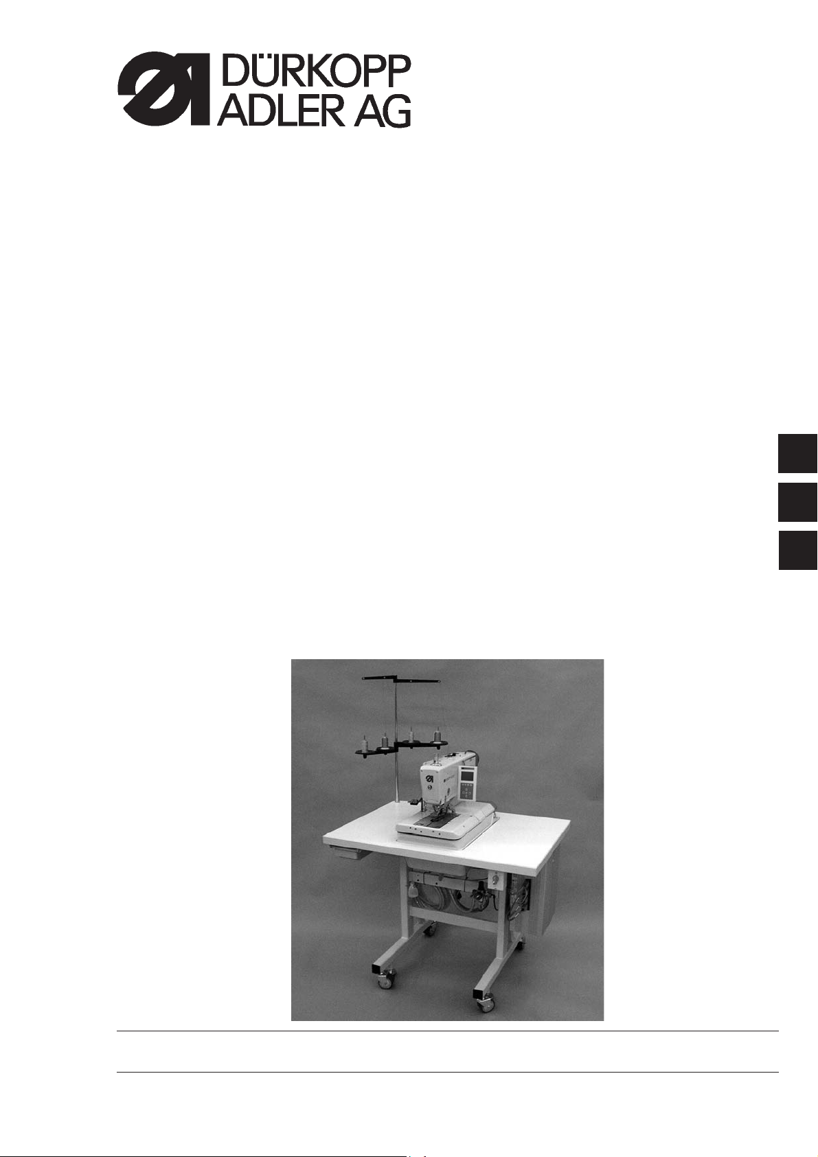
580
Double-chainstitch buttonhole automat
Single-chainstitch automat for stitched eyelets
Operating Instructions
Installation Instructions
Service Instructions
1
2
3
Postfach 17 03 51, D-33703 Bielefeld • Potsdamer Straße 190, D-33719 Bielefeld
Telefon + 49 (0) 5 21 / 9 25-00 • Telefax + 49 (0) 5 21 / 9 25 24 35 • www.duerkopp-adler.com
Ausgabe / Edition: 10/2005 Printed in Federal Republic of Germany Teile-Nr./Part.-No.: 0791 580001

580
Manual, complete
Contents
Operating Instructions
Installation Instructions
Service Instructions
Interconnection-diagram
9890 580001 B

Index Page:
Part 2: Installation Instructions cl. 580
1. Scope of delivery .................................................3
2. General notes and securing devices .....................................3
3. Table plate with dimensioning ........................................4
4. Ring bolt ......................................................5
5. Assembly of the main sw itch .........................................5
6. Assembly of the control ............................................6
7. Potential equalization ..............................................7
8. Assembly of the waste container .......................................8
9. Installation of the automatic buttonholer
9.1 Adjustingtheworkingheight...........................................9
9.2 Attachingthethreadstand............................................9
9.3 Connecting the pedal ..............................................10
9.4 Securingthestand................................................10
9.5 Connecting the maintenance unit .......................................11
9.6 Adjusting the operating pressure ........................................11
10. Lubrication
10.1 Filling the oil reservoirs .............................................13
11. Installing the sew ing s oftware
11.1 General .......................................................14
11.2 Loading the program ...............................................14
11.3 Setting the sewing equipment .........................................15
11.4 Dongle-Update via the Internet ........................................15
2
12. Sewing test ....................................................16
4
1
3
6
2
5
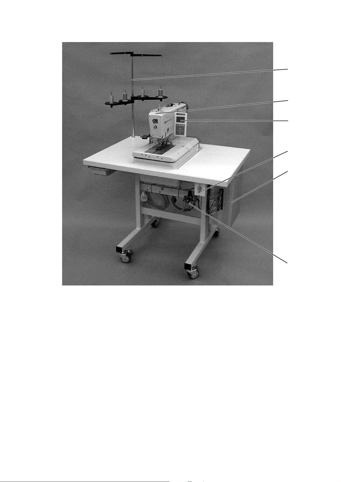
1. Scope of delivery
The scope of delivery is dependent on your order. Please check before
the assembly whether all required parts are available.
–
1 Machine head
–
2 Control
–
3 Control panel
–
4 Thread stand
–
5 Maintenance unit
–
6 Main switch
–
–
–
–
Integral sewing lamp
Spacer (right + left) for the distance between buttonhole
and fabric edge
Tools and small parts in the accessories
Optional equipment (depending on the order) e.g.:
- Stand
- Pneumatic connection package
- Foot switch
2. General notes and securing devices
2
ATTENTION !
The sewing automat must only be assembled by trained specialist
staff.
All work on the electric equipment of the automat must only be
carried out by electricians or correspondingly instructed persons.
The mains plug has to be pulled out.
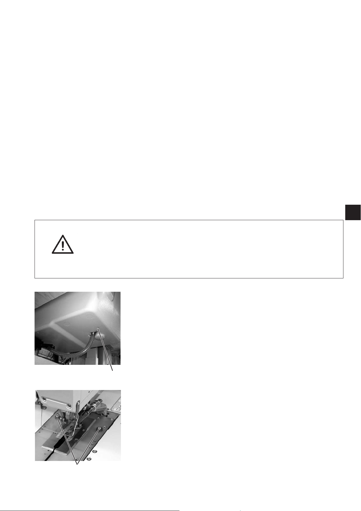
Securing devices
Before the installation of the sewing automat all securing devices have
to be removed.
–
Remove tapes and battens from the machine head, the machine
table and the stand.
–
Remove screw 1. This screw avoids that the machine head swivels
up during transportation.
–
Remove screws 2.
They will prevent the clamping plates from falling.
1
2
3
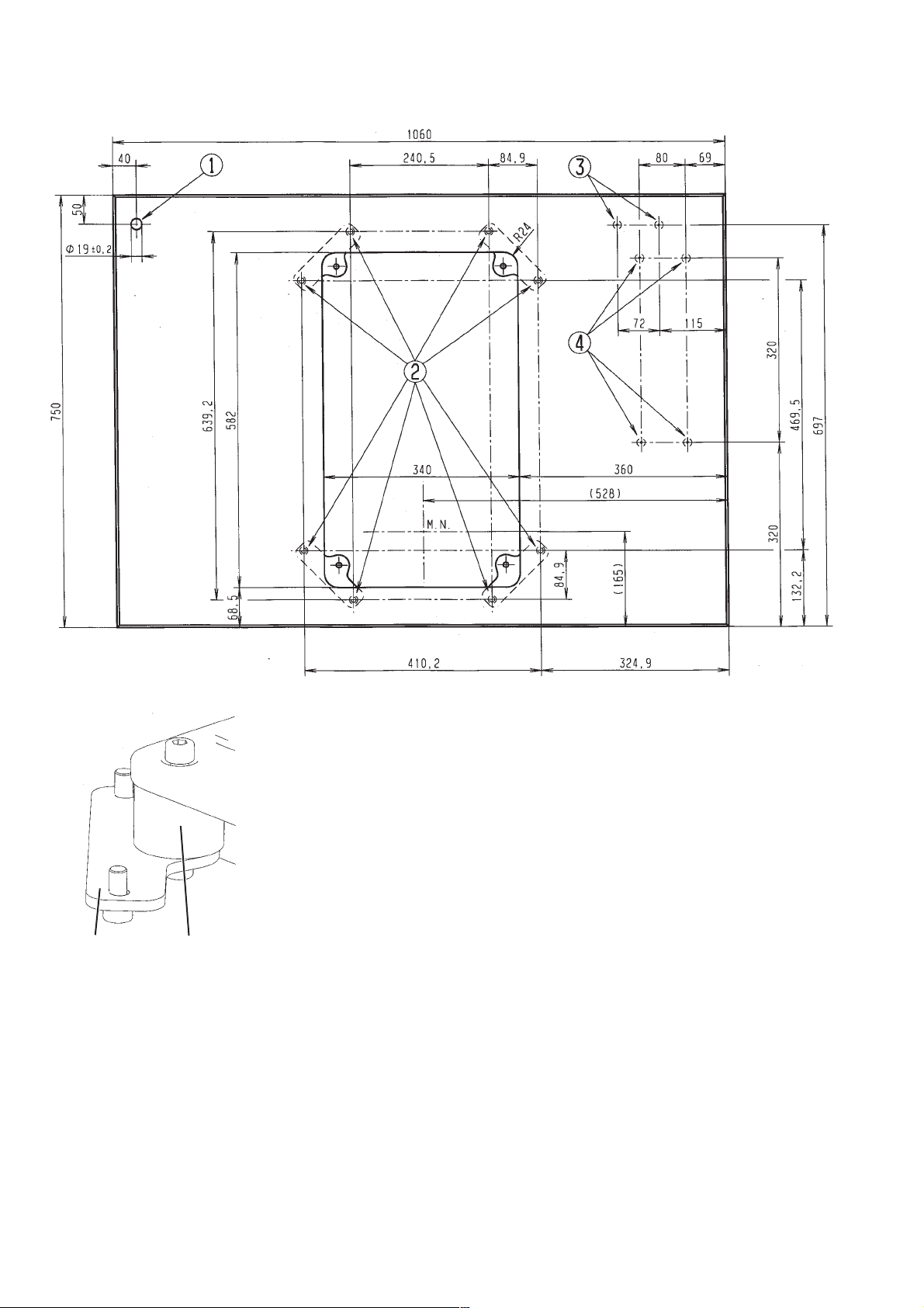
3. Table top with dimensioning
75
If you manufacture the table top yourself, take the above sketch as an
example for the dimensioning. The table top should be approx. 40 mm
thick.
Hole for the thread stand
Positions for screwing on the fish plate.
To fix the machine properly, the screws for
the fish plate should only be screwed into the screwed
inserts M8 x 25 DIN 7965 (the screwed inserts
are not included in the accessories).
Positions for screwing on the protective bracket of the control.
Positions for screwing on the control
The rubber-bonded metal buffers 5 have to be screwed between the
connectors and the machine pedestal, because otherwise vibrations
are transmitted from the automat to the stand.
(all required parts are included in the accessories)
4
 Loading...