

Adler 580 Service Manual
Manual, complete
580
Double-chainstitch buttonhole automat
Single-chainstitch automat for stitched eyelets
Operating Instructions
Installation Instructions
Service Instructions
1
2
3
Postfach 17 03 51, D-33703 Bielefeld • Potsdamer Straße 190, D-33719 Bielefeld
Telefon + 49 (0) 5 21 / 9 25-00 • Telefax + 49 (0) 5 21 / 9 25 24 35 • www.duerkopp-adler.com
Ausgabe / Edition: 09/2005 Printed in Federal Republic of Germany Teile-Nr./Part.-No.: 0791 580001

580
Manual, complete
Contents
Operating Instructions
Installation Instructions
Service Instructions
Interconnection-diagram
9890 580001 B

Index Page:
Part 3: Service Instructions Class 580
1. General notes
1.1 Necessaryprogramsetting......................................... 5
2. Adjusting the locking positions
2.1 General notes ................................................. 6
2.2 Looper and spreader eccentric....................................... 7
2.3 Threadtake-updisc............................................. 8
2.4 Throweccentric................................................ 9
3. Needle bar positioning........................................... 10
4. Aligning the looper turret ......................................... 12
5. Aligning the needle bar parallel to the looper turret ........................ 15
6. Transversal motion of the fabric support plate ........................... 17
7. Longitudinal motion of the fabric support plate ........................... 19
8. Clamping plates
8.1 Insertedclampingplates .......................................... 21
8.2 Aligningtheclampingplates........................................ 22
8.3 Adjusting the spreading ........................................... 23
8.4 Heightofthefabricclamps......................................... 25
8.5 Adjustingthelockingplate......................................... 26
8.6 Lockingoftheclampingplates....................................... 27
8.7 Adjustingthefabricclampingpressure.................................. 28
9. Adjusting the seam width
9.1 Presettingtheseamwidth ......................................... 29
9.2 Needle zero position ............................................. 32
10. Cutting knife ( eyelet knife)
10.1 Positionofthecuttingknife......................................... 33
10.2 Settingdimensions.............................................. 35
10.3 Adjustingtheknifeparalleltothecuttingblock............................. 36
10.4 Adjustingtheknifeparalleltothecuttingblockwith“Multiflex”machines ............. 37
10.5 Cuttingblockadjustment .......................................... 38
10.5.1Adjustingthecuttingblockposition(Multiflexsystem)......................... 39
10.6 Settingtheswitchforthe“Multiflex”cuttingsystem .......................... 43
10.7 Cuttingpressure ............................................... 44
10.8 Cuttingduration................................................ 44
3

Index Page:
11. Looper height ................................................ 45
12. Adjusting the loop stroke ......................................... 46
13. Needle bar height .............................................. 48
14. Distance between looper and needle .................................. 49
15. Needle protection .............................................. 50
16. Spreader.................................................... 51
17. Spreader plate ................................................ 52
18. Throat plate .................................................. 53
19. Adjusting the needle thread knife .................................... 54
20. Adjusting the fabric clamps ....................................... 56
21. Thread take-up spring ........................................... 58
22. Short trimmer for lower thread (580-112000, 580-312000)
22.1 Function sequence .............................................. 59
22.2 Initialposition................................................. 61
22.3 Adjustingthecuttingpressure/clampingpressure .......................... 63
22.4 Knife change ................................................. 64
23. Long trimmer for looper thread and gimp (580-121000 und -321000)
23.1 Cuttingpressureandcuttingmotion ................................... 65
23.2 Adjustingtheknifeoverlap......................................... 66
23.3 Position of the looper thread and gimp clamp .............................. 69
23.4 Threaddeflector ............................................... 70
24. Short trimmer for looper thread and gimp (580-141000)
24.1 Optional equipment for subclass 580-141000 .............................. 74
25. Gimp pulling device for subclass 580-141000 ............................ 75
26. Thread catcher
26.1 General notes ................................................. 76
26.2 Adjustment................................................... 77
26.3 Subsequent fitting of the thread catcher ................................. 79
27. Maintenance ................................................. 80
28. Annex
28.1 Adjusting operations without head cover ................................. 81

Index Page:
28.2 Fusesinthecontrolbox........................................... 82
28.3 Exchange of the control ........................................... 82
28.4 Adjusting the contrast of the control panel................................ 82
29. Service menu (technician level)
29.1 Activatingtheservicemenu ........................................ 83
29.2 Quittingtheservicemenu.......................................... 83
29.3 Menustructure ................................................ 84
29.3.1Menustructurewithnumbers........................................ 86
24.4 Menu items configuration automatic buttonholer ............................ 88
29.4.1 Loading position ............................................... 88
29.4.2Menuitemthrowwidth............................................ 88
29.4.3Menuitemthreadmonitor.......................................... 89
29.4.4Menuitemdutycycleofcuttingblock................................... 89
29.4.5 Menu item sewing equipment ....................................... 90
29.4.6 Menu item threading mode ......................................... 91
29.4.7 Menu item operation mode ......................................... 91
29.4.8Menuitemtensiondata........................................... 92
29.4.9MenuitemMultiflex.............................................. 93
29.5 Menu items operating configuration .................................... 94
29.5.1 Menu item language ............................................. 94
29.5.2Menuitempush-buttons........................................... 94
29.5.3Menuitembrightnessofthesewinglamp................................ 95
29.5.4 Menu item key tones ............................................. 95
29.6 Menuitemstestfunctionsmultitest.................................... 96
29.6.1Menuitemoutputtest............................................ 97
29.6.2 Menu item manual input test ........................................ 98
29.6.3 Menu item automatic input test....................................... 99
29.6.4Menuitemsewingmotortest........................................ 100
29.6.5Menuitemstepmotortest ......................................... 101
29.6.6Menuitemflashtest............................................. 102
29.6.7MenuitemRAM-test............................................. 102
29.7 Menu items test functions / Test program sewing sequence ..................... 103
29.7.1Menuitemstop................................................ 103
29.7.2Menuitemreferencestart.......................................... 103
29.7.3 Menu item continuous operation...................................... 104
29.8 Menuitemevents............................................... 105
29.8.1Menuitemallevents............................................. 105
29.8.2Menuitemlatestevents........................................... 105
3
30. Error messages ............................................... 106
31. Troubleshooting............................................... 112


1. General notes
The service manual on hand describes the adjustment of the automatic
buttonholer 580 in an appropriate sequence.
ATTENTION !
Various setting positions are interdependent.
Therefore it is absolutely necessary to make the individual
adjustments following the described order.
The operations described in this service manual must only be
executed by qualified staff or correspondingly instructed persons
respectively!
Attention: Danger of breakage !
Before recommissioning of the automatic buttonholer after
disassembly operations first carry out the necessary adjustments
according to these service instructions.
Before all setting operations of parts involved in the stitch
formation:
–
Insert a new needle without any damage.
Caution: Danger of injury !
In case of repair, alteration and maintenance work:
–
Adjusting operations and function tests when the machine is
running
–
Adjusting operations in the needle zone
–
1.1 Necessary program setting
For adjusting the automatic buttonholer the following buttonhole shape
has to be set at the control panel:
–
–
–
–
Turnthemainswitchoff.
Exception:
Adjustments carried out with the help of test or adjusting programs.
Carry out adjusting operations and function tests of the running
machine only under observation of all safety measures and with
utmost caution.
In order to avoid injuries remove the corresponding parts before
carrying out adjusting operations.
Exception:
The parts are absolutely necessary for the adjusting operations.
Buttonhole without bartack
Connecting stitch = 0
No cutting space
Set the connecting stitch to “wide” (see chapter 9 “Setting the seam
width”)
3
Note!
The set seam width has to be checked not only mechanically but
also at the control panel!
5
2. Adjusting the locking positions
2.1 General notes
3
With the help of the locking positions an easy adjustment of the needle
motion to the looper and spreader motions is possible.
When the arm shaft is in locking position, the rotary thread take-up
disc and the eccentrics for the spreaders, the loopers and the
connecting stitch have to be in locking position, too.
The positions have been set by the manufacturer in such a way that
standard material can be sewn with the 580.
If you want to use other needle sizes, thread sizes or materials, you
may have to set positions slightly differing from the staking-out
position.
The locking pins are included in the accessories of the machine and
have a diameter of 5 mm.
6
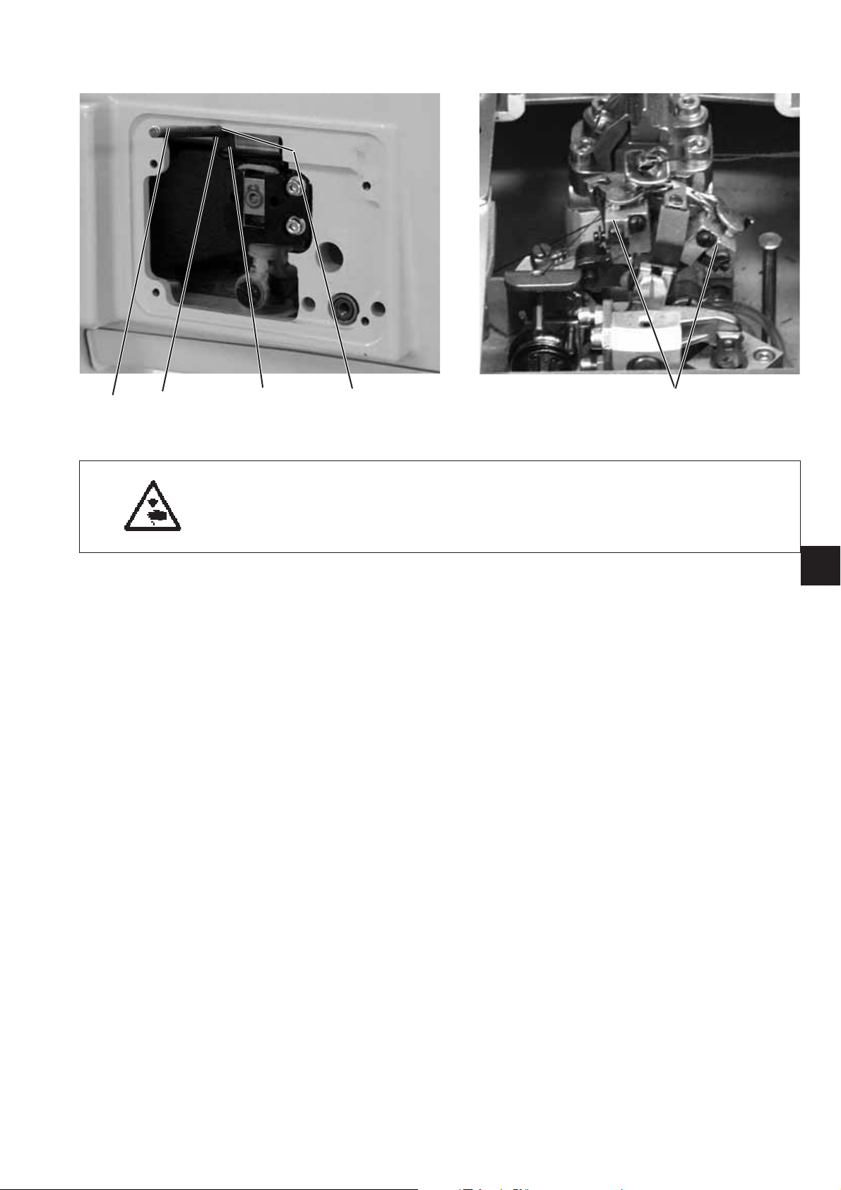
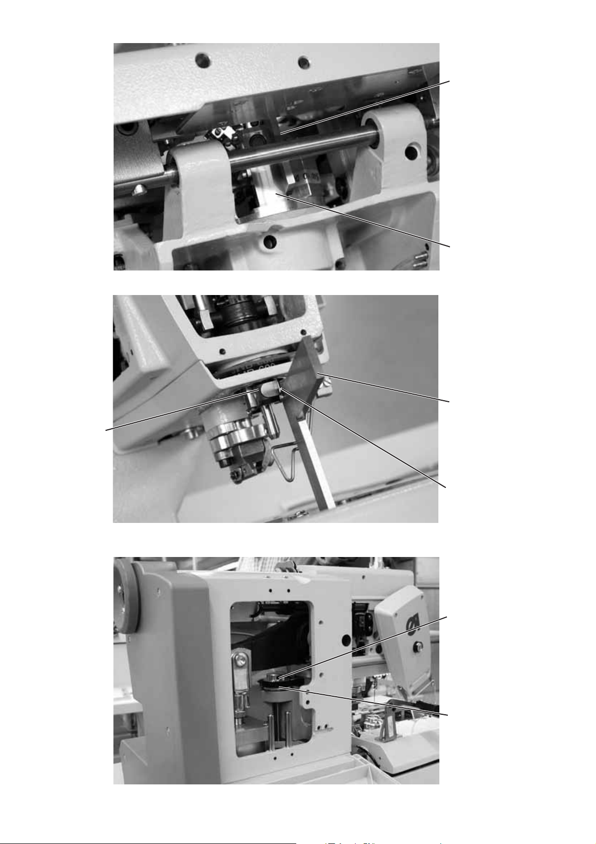
2.2 Looper and spreader eccentric
1
Caution: Danger of injury!
Turnthemainswitchoff.
Adjust the eccentrics only with the sewing machine switched off.
Standard checking
When the arm shaft is locked with locking pin 1, it should
be possible to lock the looper eccentric 3 and the spreader
eccentric 4, too.
–
Lock the arm shaft with locking pin 1.
Important !
In this position the needle bar must be in the upper dead center in
front of the left stitch.
–
Check with locking pin 2 whether the looper eccentric 5 and the
spreader eccentric 6 can be staked out.
64 3 25
3
Correction
–
Lock the arm shaft with locking pin 1.
–
Loosen the screws at the looper eccentric 3.
–
Turn and lock the eccentric.
–
Tighten the screws.
–
Loosen the screws at the spreader eccentric 4.
–
Turn and lock the eccentric.
–
Tighten the screws.
7
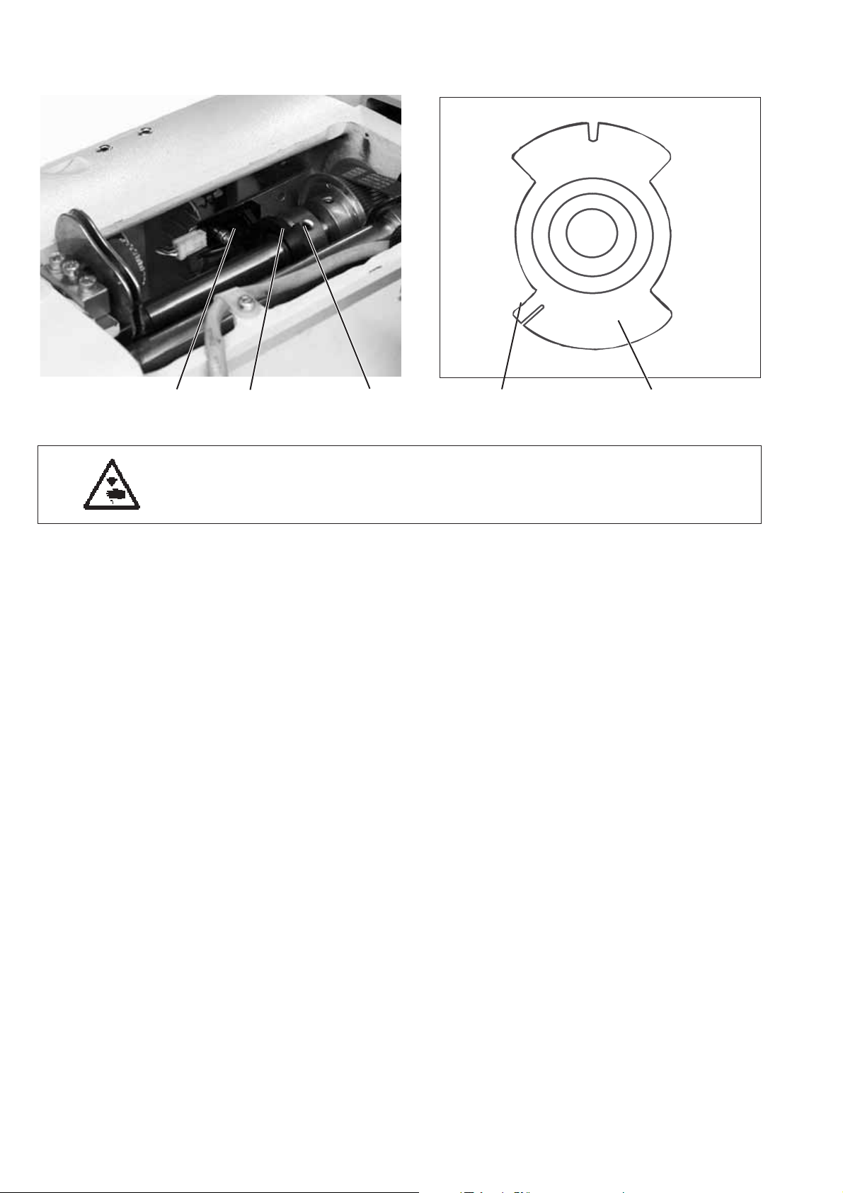
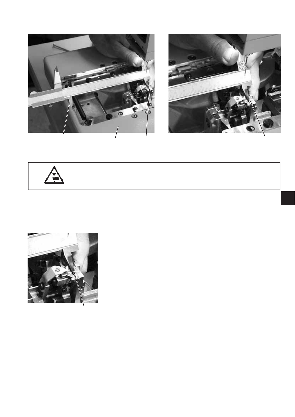
2.3 Thread take-up disc
21
Caution: Danger of injury!
Turnthemainswitchoff.
Adjust the thread take-up disc only with the machine
switched off.
654 3
Standard checking
When the arm shaft has been locked with the locking pin 2
in such a way that the looper turret is in its left end position (left stitch),
the rotary thread take-up disc 6 should be positioned so that
a drill 4 (2 mm diameter) pushed through the drill-hole of the thread
take-up disc rests on the right surface 3.
Correction
–
Unscrew the tension plate 1.
–
Loosen the screws at the (timing) gear 5.
–
Insert the drill 4 through the drill-hole in the thread take-up disc 6.
–
Turn the thread take-up disc until the drill 4 abuts on the surface 3.
–
Tighten the screws at the (timing) gear 5.
8
2.4 Throw eccentric
43 2 1
Caution: Danger of injury!
Turnthemainswitchoff.
Adjust the throw eccentric only with the machine switched off.
Standard checking
When the looper support 5 is in its right end position (right stitch),
the locking pin 4 inserted in the eccentric 2 should abut in the
indentation 1 at the arm.
–
Turn the arm shaft in such a way that the looper support is on the
right side (right stitch).
–
Put the locking pin 4 in the drill-hole 3 of the eccentric 2.
–
Check whether the locking pin 4 abuts in the indentation 1 of the
arm.
Correction
–
Loosen the screws at the eccentric 2.
–
Position the eccentric with the locking pin right on top against the
arm.
–
Tighten the screws at the eccentric 2.
5
3
9
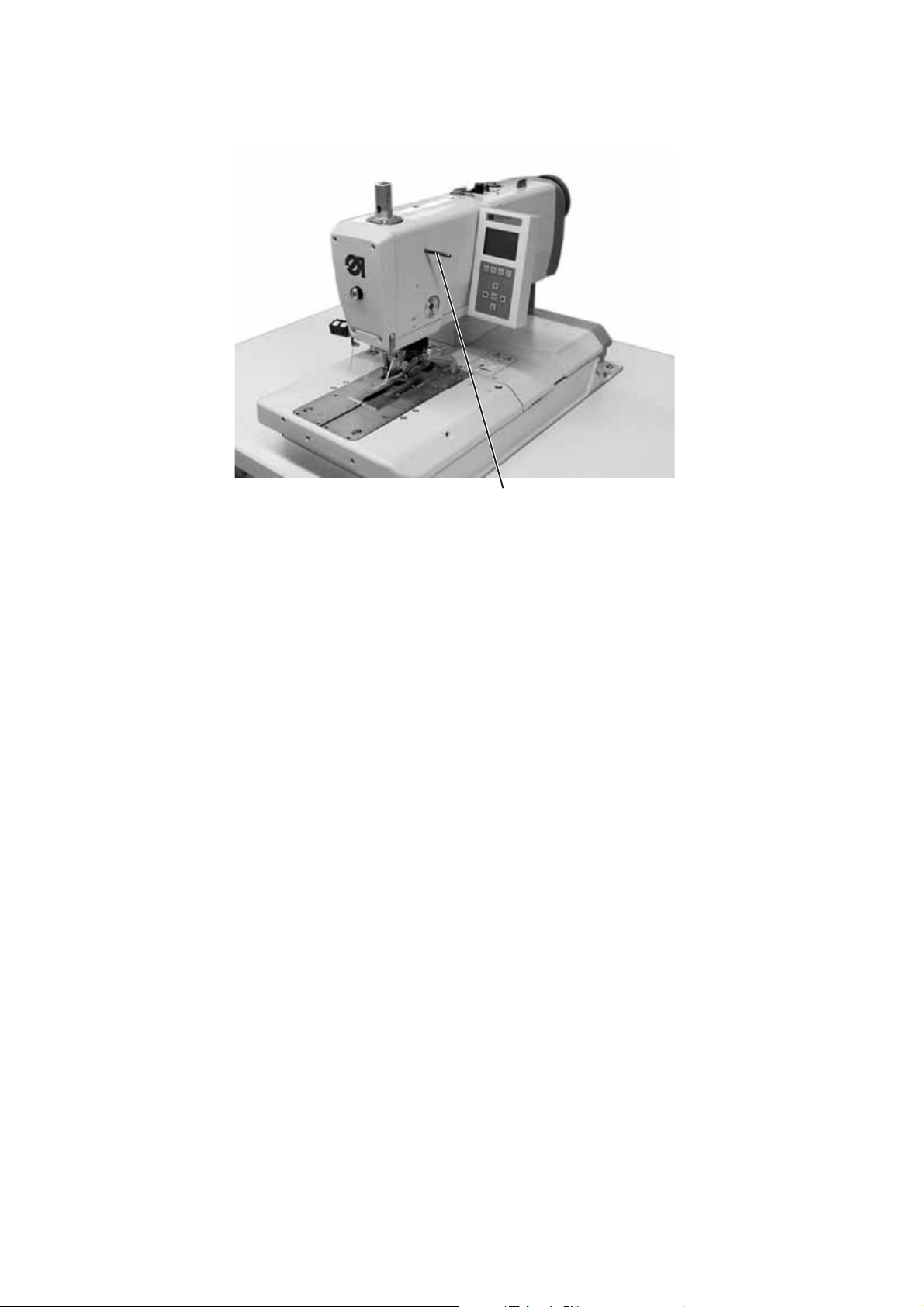
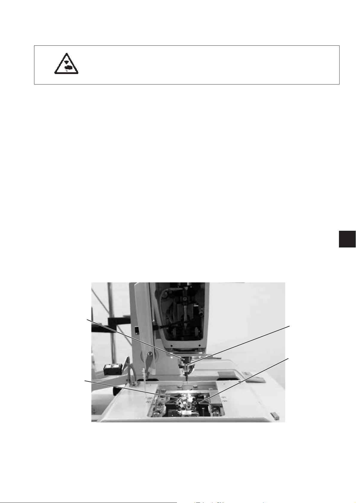
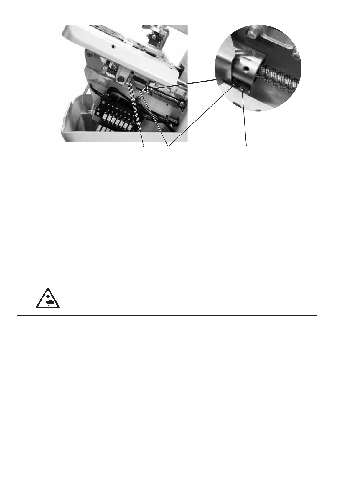
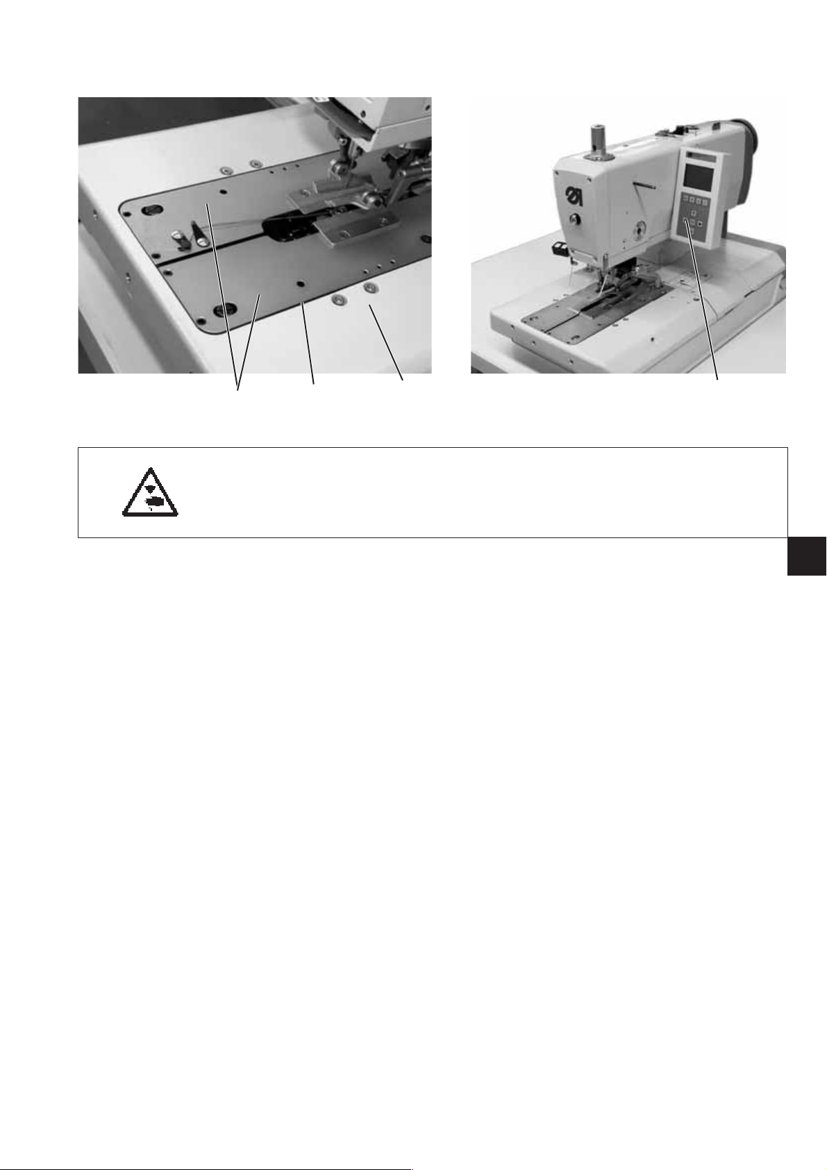
3. Needle bar positioning
32 1
Caution: Danger of injury!
Exercise utmost caution when making adjustments with the machine
running.
Standard checking
When the machine positions automatically after being switched on, the
needle bar must be in the top dead centre. The looper turret is in its
right end position (right stitch) then.
–
Switch the machine on.
The machine positions automatically.
–
Check whether the needle bar is in the top dead centre and
whether the looper turret is in its right end position (right stitch).
42
10
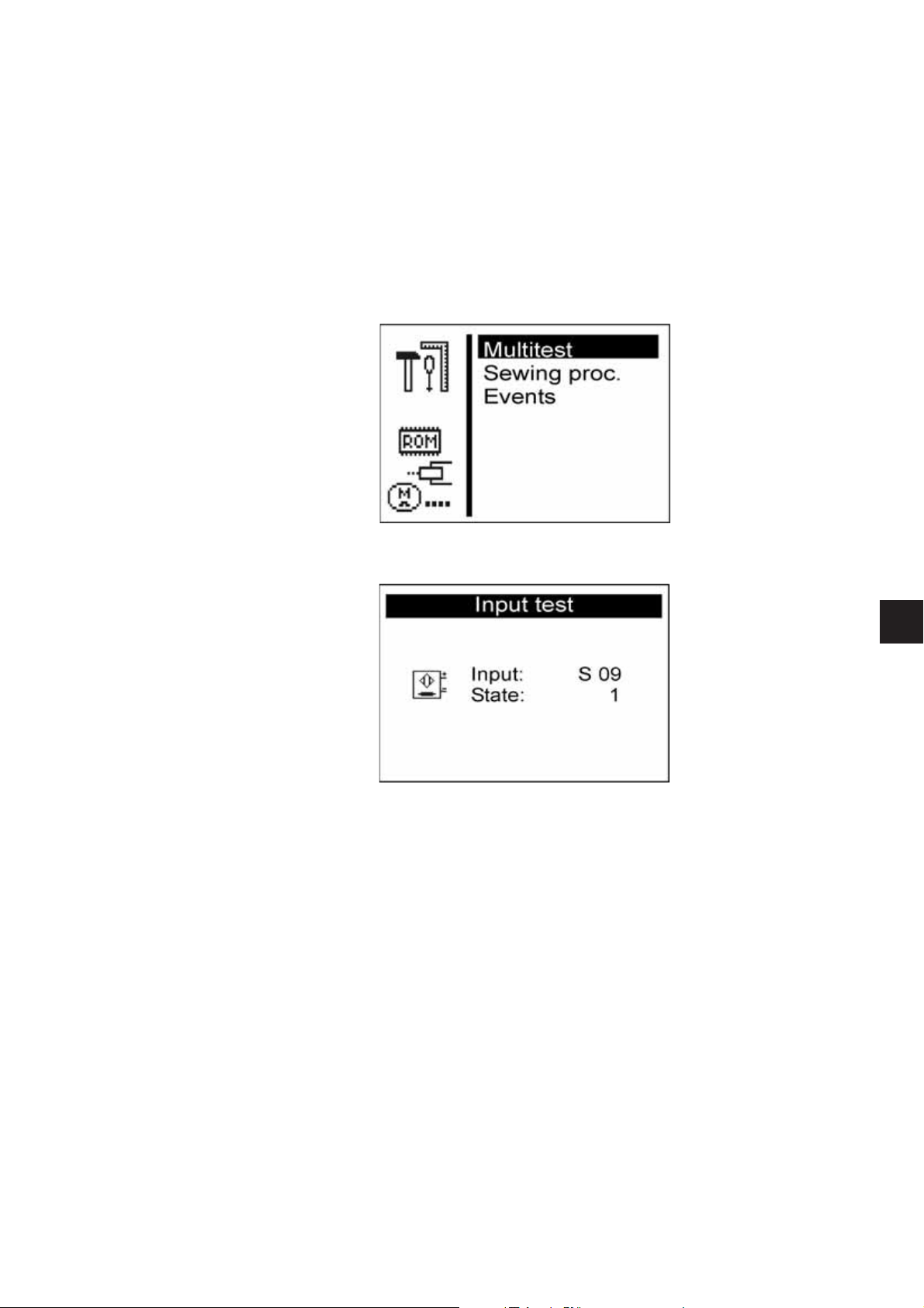
Correction
–
Switch the machine switch on.
The machine positions automatically.
–
Move the needle bar in the correct position by handwheel (right
stitch).
–
Press key “F”.
–
Enter code “2548”.
–
Press key “OK”.
The controls switches to the technician level.
–
Select menu “Test functions".
–
Press key “OK”.
–
Select menu “Multitest”.
–
Press key “OK”.
–
Select menu “Input test”.
–
Press key “OK”.
–
Loosen screw 1 at the switch segment 2.
–
Turn the segment in such a way that the light barrier 3 at the
flank 4 engages.
The switching signals are indicated on the control panel
(input S100).
–
Tighten screw 1 at the switching segment 2
Note
The switching segment must be in the middle of the light barrier.
–
Switch the machine off/on and check the positioning.
3
11
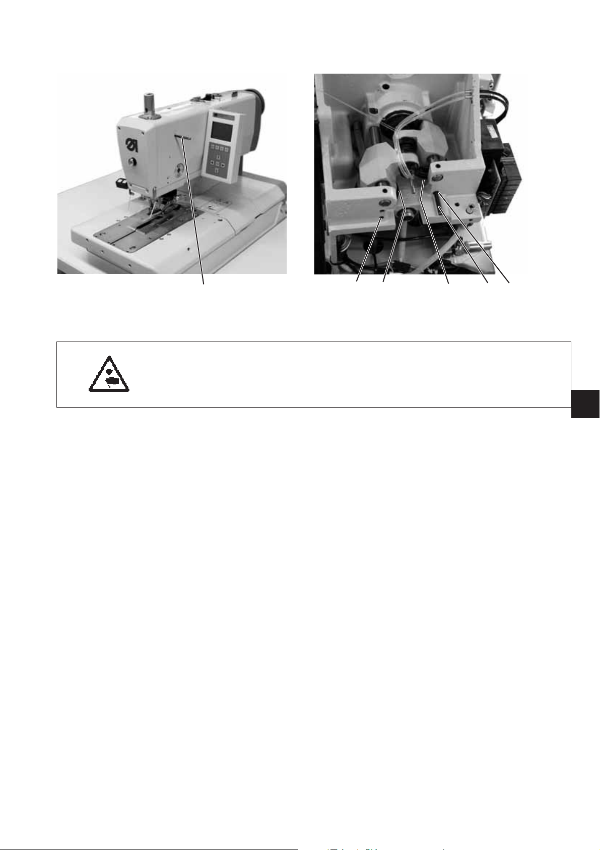
4. Aligning the looper turret
21
Caution: Danger of injury!
Turnthemainswitchoff.
Align the looper turret only with the machine switched off.
Note
Please observe the necessary program setting as described in
chapter 1.1.
Standard checking
When the machine has reached its initial position after switching on
the main switch, it must be possible to lock the looper turret 2 with the
locking pin 1.
–
Switch the machine on
The machine and the fabric support plate run to their initial
position.
–
Switch the machine off.
–
Check whether the looper turret 2 can be locked with locking pin 1.
3
12

4
Correction
–
Remove the clamping plates 4.
–
Switch the machine on
The machine runs to its initial position.
–
Switch the machine off.
–
Loosen the clamping screw in the (timing) gear with
the Allen key 3.
–
Turn the looper turret in such a way that it can be locked with pin 1.
–
Tighten the clamping screw with the Allen key 3.
3
13
5
6
5
8
7
9
14
10
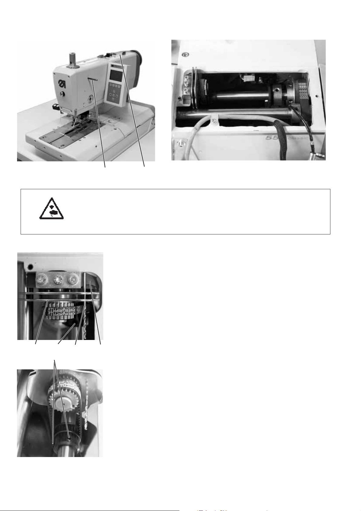
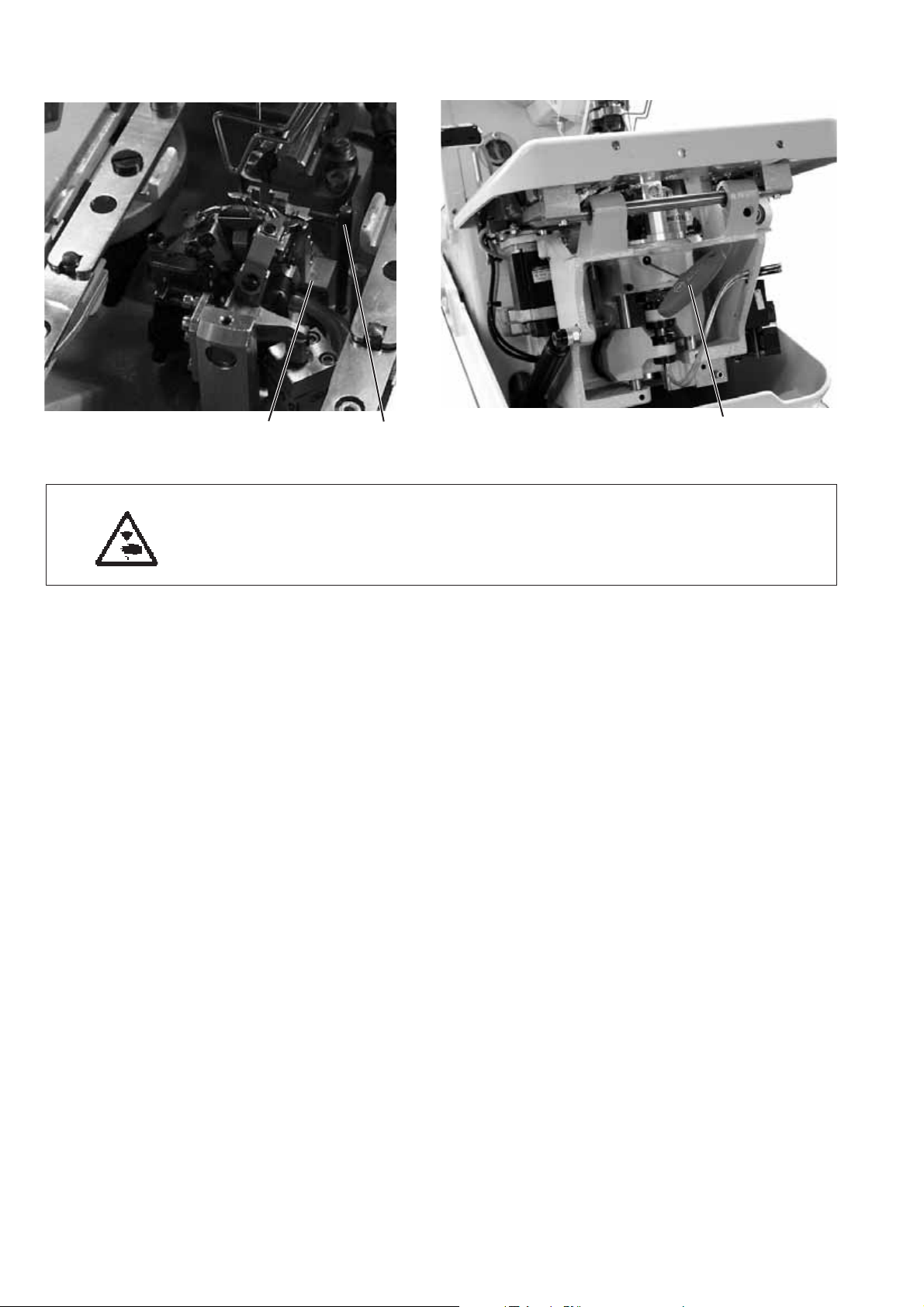
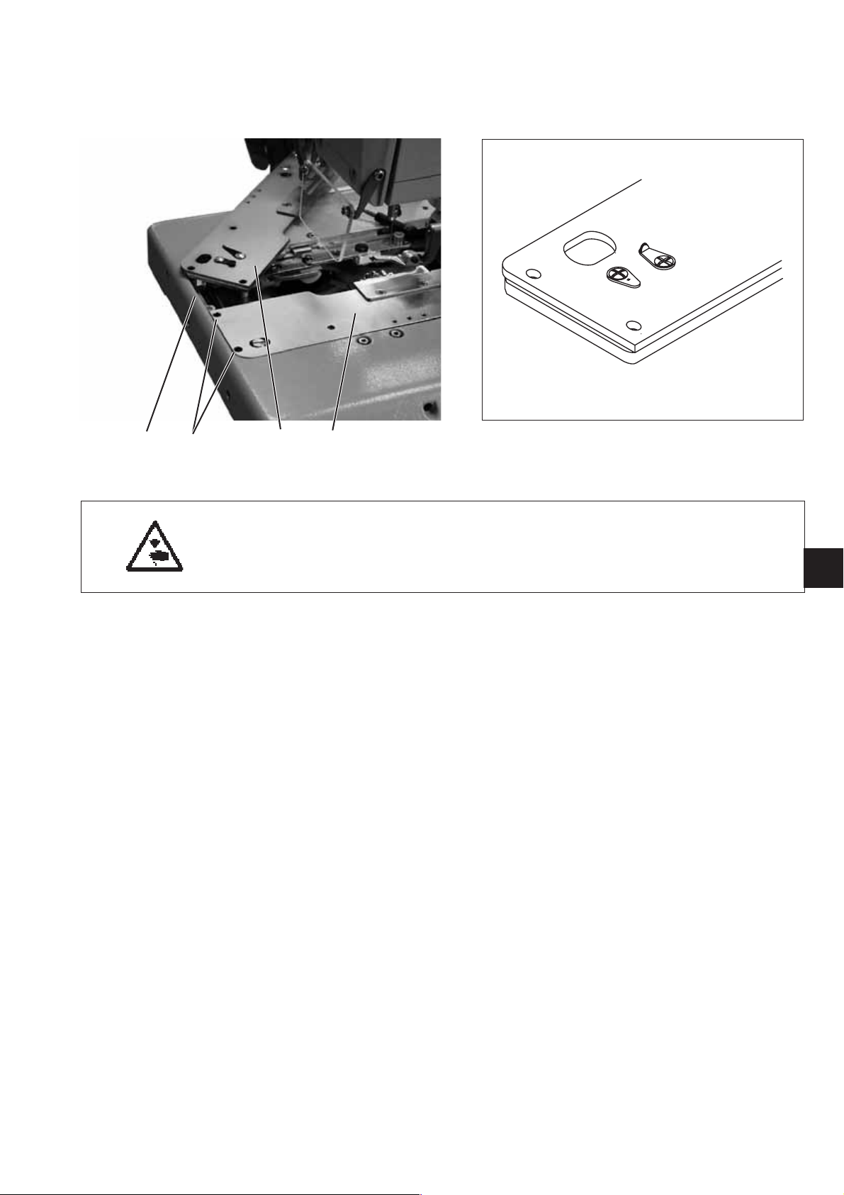
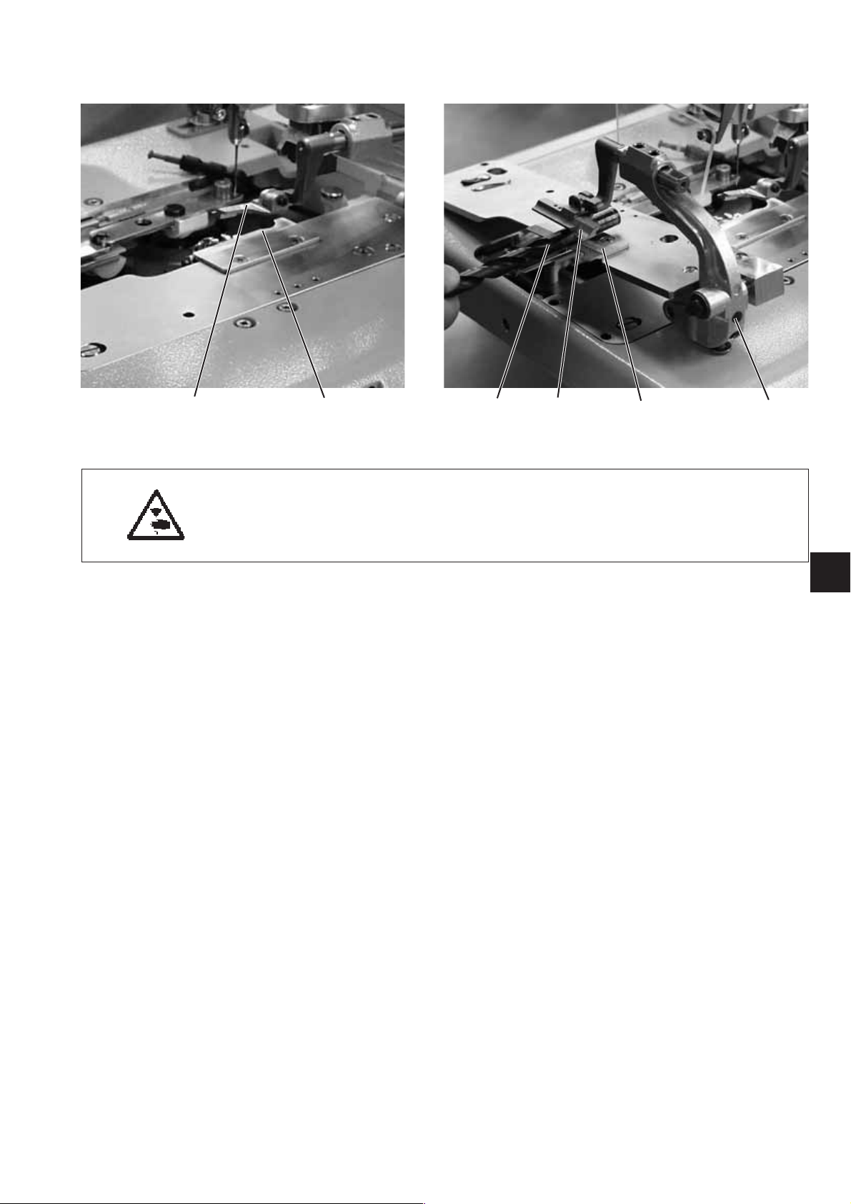
5. Aligning the needle bar parallel to the looper turret
Caution: Danger of injury!
Turnthemainswitchoff.
Adjust the needle bar only with the main switch switched off.
Standard checking
The needle bar 1 and the looper turret 3 must be in parallel position.
–
Remove the cutting block.
–
Unscrew the finger protection and the head cover.
Note !
Do not separate the cable from the head cover.
–
Switch the machine on
The machine runs to its initial position.
–
Switch the machine off.
–
Lock the looper turret with locking pin 2.
–
Position a square 5 at the right side 6 of the looper turret.
–
Check whether the screw 7 at the needle bar guide 8 abuts on the
square.
Correction
–
Loosen the screws 9 at the (timing) gear 10.
–
Turn the needle bar guide 4 correspondingly.
–
Tighten the screws 9 at the (timing) gear 10.
–
Switch the machine on.
–
Check the needle bar position.
3
4
1
2
3
15
X2
11
X1
16
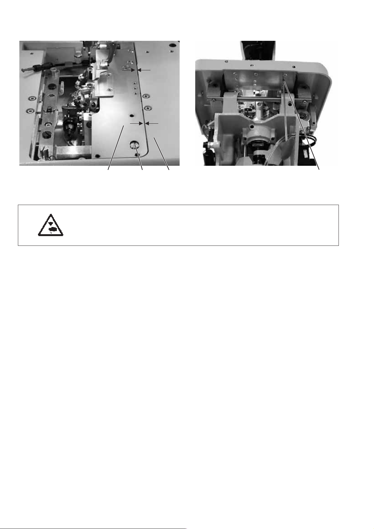
432

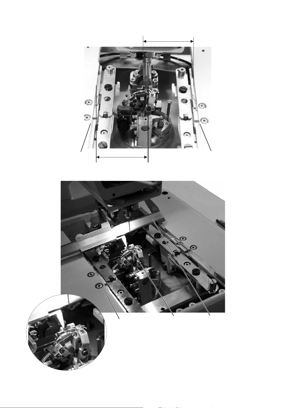
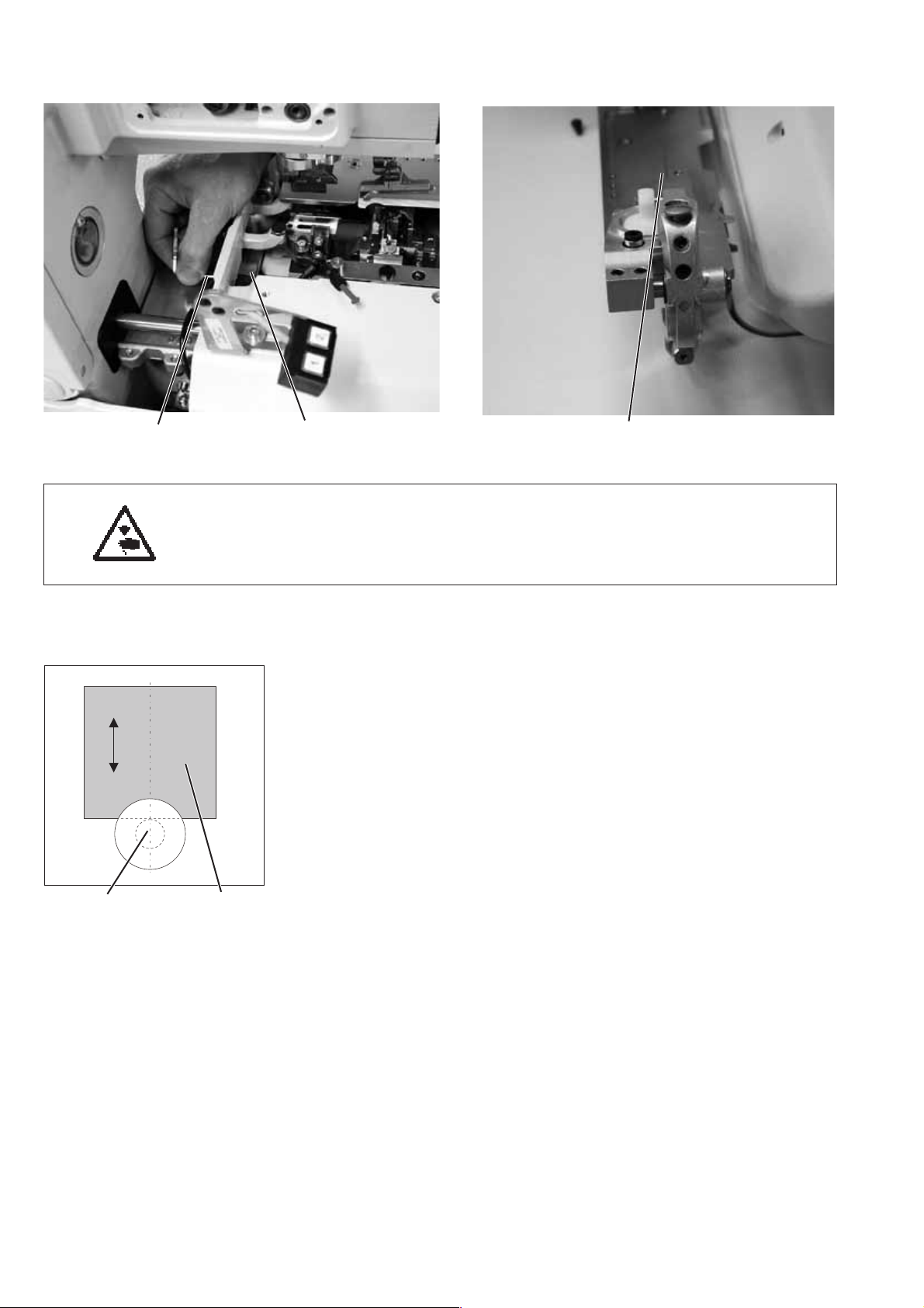
6. Transversal motion of the fabric support plate
Caution: Danger of injury!
Exercise utmost caution when making adjustments with the machine
running.
Note
Please observe the necessary program setting as described in chapter 1.1.
Standard checking
The looper turret 3 must be in the centre of the fabric support plate 4.
When the automatic buttonholer is in reference position, the
dimensions X1 and X2 must be equal when the fabric support plate is
adjusted correctly.
The distance between reference switch 5 and switch sheet 6 must not
exceed 0.5 mm.
–
Switch the machine on.
–
Press key “F” at the control panel.
–
Enter code “2548”.
–
Press key “OK”.
The control switches to the technician level.
–
Select menu “Test functions”.
–
Press key “OK”.
–
Select menu “Sewing proc.”.
–
Press key “OK”.
–
Select menu “Start ref.”.
–
Press key “OK”
The machine runs to its initial position.
–
Check the dimension X1 (right edge of the throat plate groove to
the left edge of the fabric support plate) with the vernier caliper 2.
–
Check the dimension X2 (left edge of the throat plate groove to the
right edge of the fabric support plate).
3
65
17
76 85
Correction
–
Press key “F” at the control panel and switch the machine on.
–
Enter code “2548”.
–
Press key “OK”.
The control switches to the technician level.
–
Select menu “Test functions”.
–
Press key “OK”.
–
Select menu “Sewing proc.”.
–
Press key “OK”.
–
Select menu “Start ref.”.
–
Press key “OK”
The machine runs to its initial position.
Caution: Danger of injury!
Exercise utmost caution when making adjustments with the machine
running.
–
Shift the fabric support plate manually in such a way that the
dimensions X1 and X2 are equal.
–
Loosen screw 7.
–
Turn the switch sheet 6 to the switch actuation point.
When turning the switch sheet 6 the switching signals are indicated
on the control panel (input r1).
–
Tighten screw 7.
–
Switch the machine off and on again.
–
Let the machine move to its initial position and check the position
of the fabric support plate.
18
Correction of the distance betw een reference switch and sw itch
sheet
–
Loosen the nuts 8.
–
Screw the reference switch 5 out or in so that the distance between
reference switch 5 and switch sheet 6 does not exceed 0.5 mm.
–
Tighten the nuts 8.
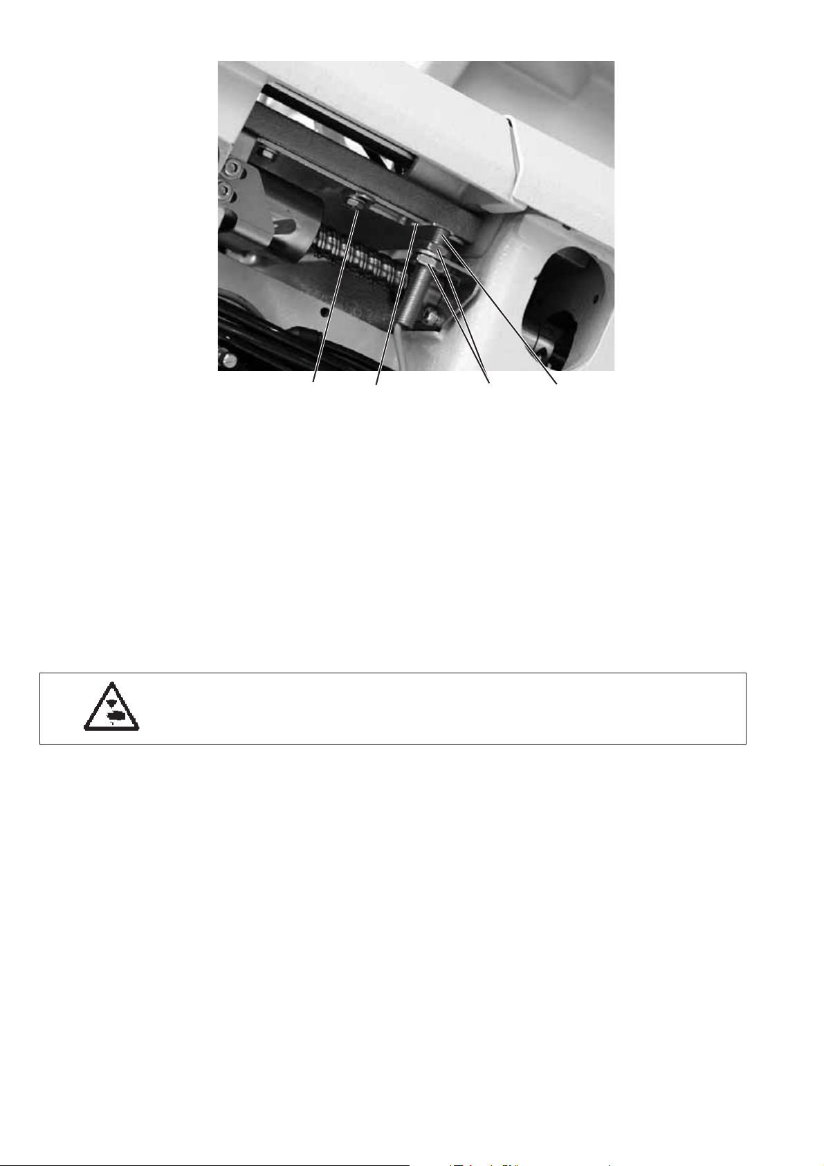
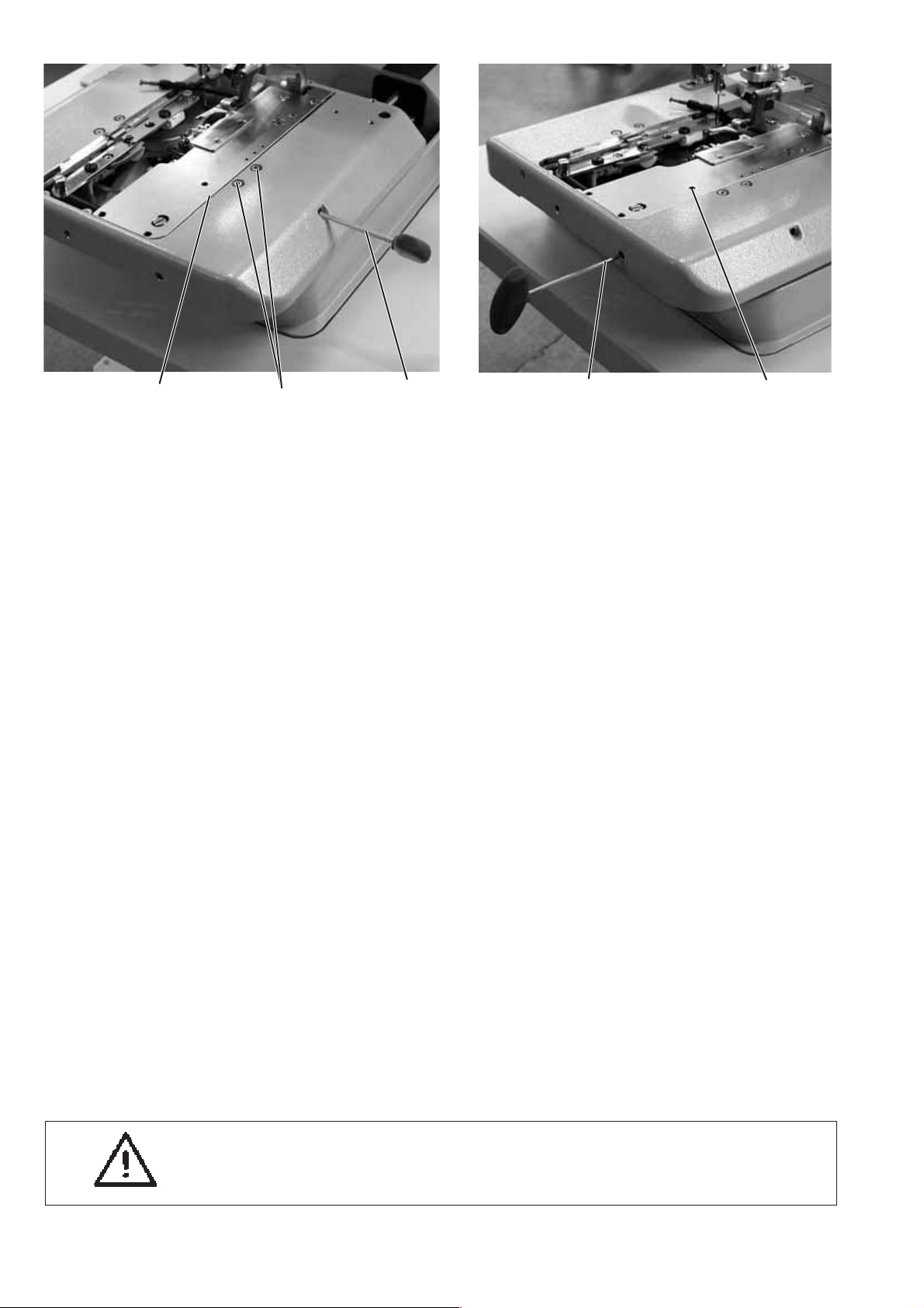
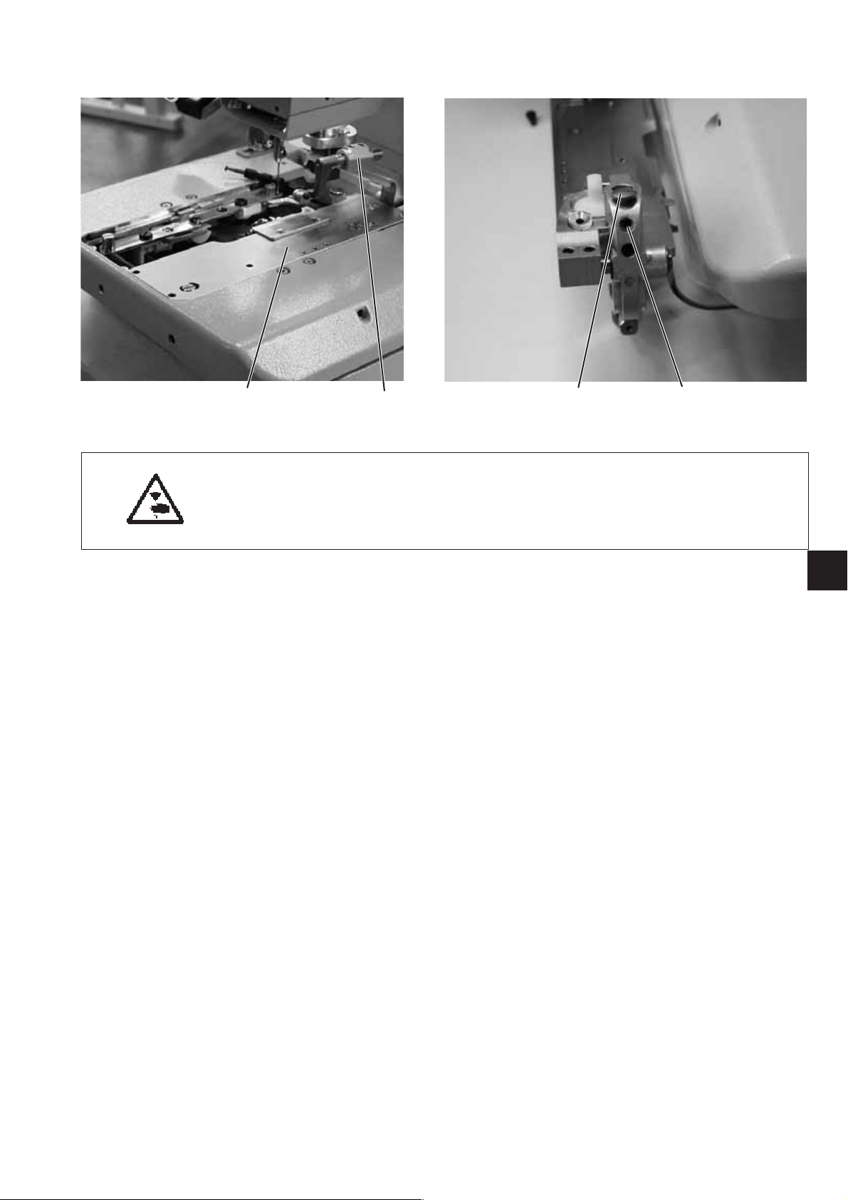
7. Longitudinal motion of the fabric support plate
321 1
Caution: Danger of injury!
Exercise utmost caution when making adjustments with the machine
running.
3
Note
Please observe the necessary program setting as described in
chapter 1.1.
Standard checking
When the machine is in reference position, the distance between the
edge 3 of the fabric support plate 2 and the front edge 1 of the throat
plate support should amount to approx. 113 mm.
The distance between reference switch and switch sheet must not
exceed 0.5 mm.
–
Switch the machine on.
–
Press key “F” at the control panel.
–
Enter code “2548”.
–
Press key “OK”.
The control switches to the technician level.
–
Select menu “Test functions”.
–
1
Press key “OK”.
–
Select menu “Sewing proc.”.
–
Press key “OK”.
–
Select menu “Start ref.”.
–
Press key “OK”
The machine runs to its initial position.
–
Switch the machine off.
–
Check the distance between edge 3 of the fabric support plate and
front edge 1 of the throat plate support.
19
54 6
Correction
–
Press key “F” at the control panel and switch the machine on.
–
Enter code “2548”.
–
Press key “OK”.
The control switches to the technicial level.
In this mode the step motors are dead.
–
Select menu “Test functions”.
–
Press key “OK”.
–
Select menu “Sewing proc.”.
–
Press key “OK”.
–
Select menu “Start ref.”.
–
Press key “OK”
The machine runs to its initial position.
Caution: Danger of injury!
Exercise utmost caution when making adjustments with the machine
running.
–
Shift the fabric support plate manually to the desired dimension.
–
Loosen the screws 5.
–
Set the switch sheet 4 to the switch actuation point.
When shifting the switch sheet 4 the switching signals are
indicated on the control panel (input r2).
–
Tighten the screws 5.
–
Switch the machine off and on again.
–
Let the machine move to its initial position and check the
dimension.
20
Correction of the distance betw een reference switch and sw itch
sheet.
–
Loosen the nut.
–
Screw the reference switch 6 out or in so that the distance between
reference switch 6 and switch sheet 4 does not exceed 0.5 mm.
–
Tighten the nut.
8. Clamping plates
8.1 Inserted clamping plates
43 21
ô=0
Caution: Danger of injury!
Turnthemainswitchoff.
Adjust the clamping plates only with the machine switched off.
Standard checking
The inserted clamping plates 1 and 2 should be in the holding
groove 4 of the fabric support plate in parallel position and without
clearance.
Inserting and removing must, however, be fingertip easy.
–
Insert both clamping plates and check whether there is as little
clearance as possible.
–
Remove the clamping plates and check whether this is easily
possible.
Correction
–
Adjust the screws 3 correspondingly.
3
21
8.2 Aligning the clamping plates
X2
X1
321
Caution: Danger of injury!
Turnthemainswitchoff.
Adjust the clamping plates only with the machine switched off.
Standard checking
Both clamping plates 3 must be adjusted in such a way that the
distance between clamping plate and fabric support plate 1 is
equal on the entire length (distance X1 = distance X2).
–
Put on the right clamping plate.
–
Check distance X1 and X2.
Correction
–
Insert the right clamping plate.
–
Loosen the screw 4 with an Allen key.
–
Turn the eccentric 2 correspondingly.
–
Tighten the screw 4.
–
Insert and adjust the left clamping plate.
4
22
8.3 Adjusting the spreading
2X 1 4
Caution: Danger of injury!
Exercise utmost caution when making adjustments with
the machine running.
Standard checking
The distance X between the clamping plates 2 and the fabric support
plate 1 should amount to 1.3 mm (non-spreaded) and to 0.3 mm
(spreaded).
–
Insert the clamping plates 2 and switch the machine on.
–
Press key “F”.
–
Enter code “2548”.
–
Press key “OK”.
The control switches to the technician level.
–
Select menu “Test functions”.
–
Press key “OK”.
–
Select menu “Multitest”.
–
Press key “OK”.
–
Select menu “Output test”.
–
Press key “OK”.
–
Select function “Y03” (closing the fabric clamp).
–
Press key ”OK”.
The fabric clamps close.
–
Check whether the distance X amounts to 1.3 mm.
–
Select function “Y04”.
–
Press key ”OK”.
The clamping plates spread.
–
Check whether the distance X amounts to 0.3 mm.
3
23
X65
Correction clamping plate
–
Switch the machine on.
The machine positions automatically.
–
Move the needle bar to the correct position by handwheel (right
stitch).
–
Press key “F”.
–
Enter code “2548”.
–
Press key “OK”.
The control switches to the technician level.
–
Select menu “Test functions”.
–
Press key “OK”.
–
Select menu “Multitest”.
–
Press key “OK”.
–
Select menu “Output test”.
–
Press key “OK”.
–
Select function “Y03” (closing the fabric clamp).
–
Press key ”OK”.
The fabric clamps close.
–
Loosen the screws 6.
–
Set the distance X to 1.3 mm (basic adjustment) with the Allen
key 5.
–
Tighten the screws 6.
–
Select function “Y04”.
–
Press key ”OK”.
The fabric clamps spread.
–
Loosen screw 7.
–
Set the distance X to 0.3 mm with the Allen key 8.
–
Tighten screw 7.
87
24
–
Adjust the left clamping plate as well.
Note!
The desired spreading must only be set with the screws 6 according
to the sewing material used.
8.4 Height of the fabric clamps
32
Caution: Danger of injury!
Turnthemainswitchoff.
Adjust the fabric clamp height only with the machine switched off.
Standard checking
The distance between the open fabric clamps 2 and 3 should amount
to 12 mm.
–
Remove the clamping plates.
–
Open the clamping plate and test e.g. with a twist drill Ø 12 mm
whether the fabric clamps 2 and 3 have the required distance.
Correction
–
Adjustthedistancewithcorepin1.
Ø12mm 3 2 1
3
25
8.5 Adjusting the locking plate
21
Caution: Danger of injury!
Turnthemainswitchoff.
Adjust the locking plates only with the machine switched off.
Standard checking
The locking plates 1 have to be adjusted in such a way that the
stops 3 of the clamping plates abut centrally and as tight as possible.
–
Insert the clamping plates.
–
Check the position of the locking plates 1 to the stop 3.
Correction
–
Adjust the locking plate 1 with the special spanner 2 (in the
accessories).
3
26
31
8.6 Locking of the clamping plates
21
Caution: Danger of injury!
Exercise utmost caution when making adjustments with
the machine running.
Standard checking
There must be a minimum clearance in the height of the inserted
clamping plates 2 when:
no material is loaded.
·
approx. 8 mm thick material is loaded and the clamps are closed.
·
–
Insert the clamping plates.
–
Switch the machine on.
–
Close the fabric clamps.
–
Check at the fabric clamp fixture 1 whether the clamping plate can
be minimally lifted.
–
Load 8 mm thick material.
–
Check at the fabric clamp fixture 1 whether the clamping plate can
be minimally lifted.
43
3
Correction
–
Switch the machine off.
–
Remove the clamping plates.
–
Loosen the threaded pin 3.
–
Adjust the stop 4.
–
Tighten the screws 3.
27
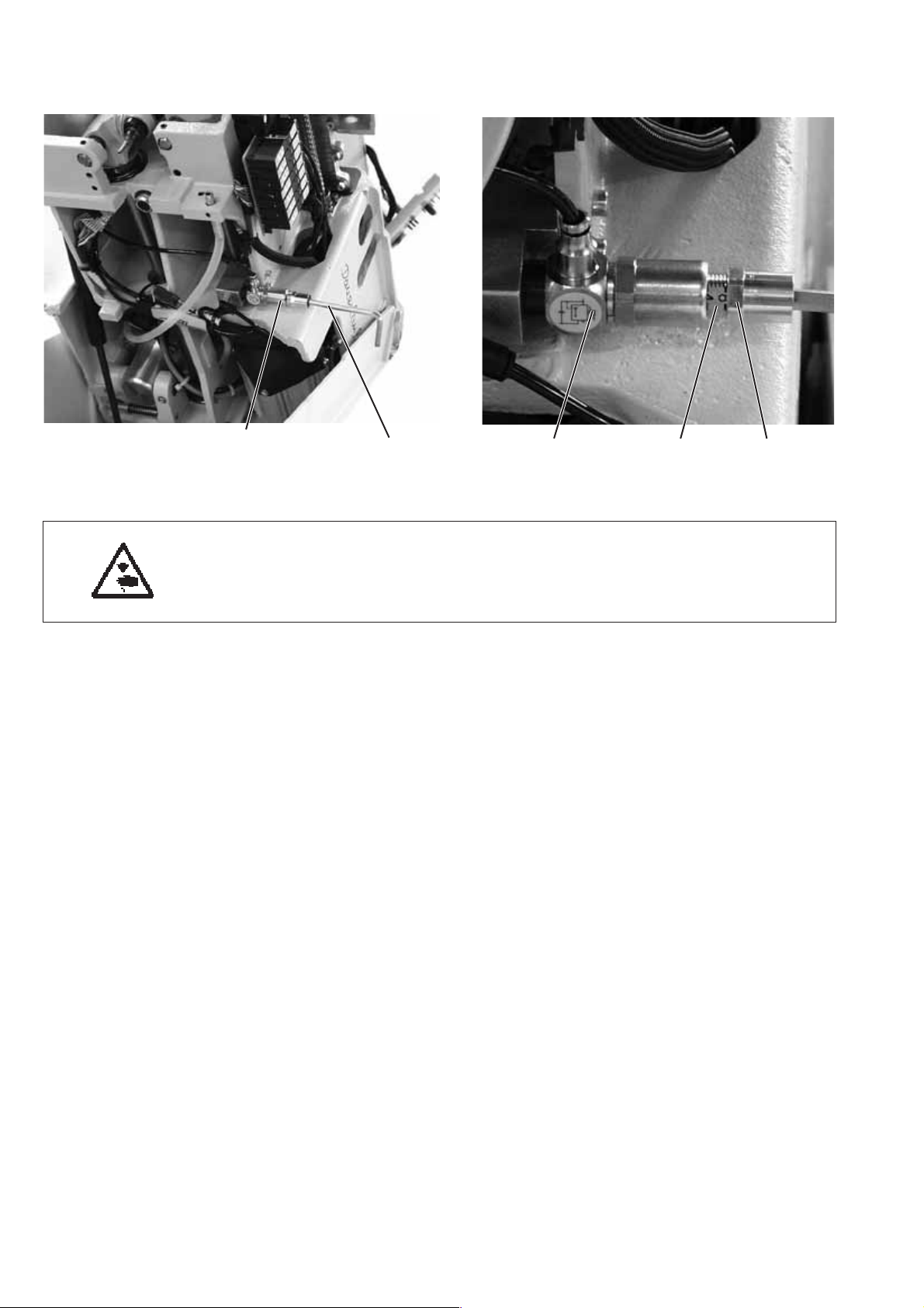
8.7 Adjusting the fabric clamping pressure
21
Caution: Danger of injury!
Turnthemainswitchoff.
Adjust the fabric clamping pressure only with the machine switched off.
Standard checking
The clamping pressure should be adjusted in such a way that the
sewing material is clamped safely and tightly.
Please observe that the sewing material is not damaged by a too high
pressure.
The standard pressure amounts to 4 bar.
Correction
–
Switch the machine off and tilt it up.
–
Loosen the counter-nut 3 at the regulator 2 so that the scale 4 is
visible.
–
Adjust the pressure with the Allen key 1.
–
Tighten the counter-nut 3.
–
Check the clamping of the material.
243
28
 Loading...