

Page 1

Contents page:
Preface and general safety instructions
Part 1: Operating instructions class 579
Program version 579A04
1. Product description
1.1 Designated use ..................................................5
1.2 Brief description..................................................5
1.3 Subclasses.....................................................7
1.4 Product structure .................................................8
2. Technical data ..................................................9
3. Operation
3.1 Needles, yarns and gimps ...........................................10
3.2 Removing and replacing the clamp plates..................................11
3.3 Changing the needle ..............................................12
3.4 Threading the upper thread ..........................................13
3.5 Threading the bobbin thread..........................................14
3.6 Threading the gimp thread (versions 579-121000, 579-141000 and 579-151000 only) .......15
4. Thread tensions
4.1 Needle- and bobbin-thread tension......................................16
4.2 Bobbin-thread-tensioning spring .......................................17
5. Changing the cutting blocks ........................................18
6. Spreading the workpiece...........................................19
7. Hand switches .................................................19
1
8. Switching on - Switching off - Firm hold
8.1 Switching on ...................................................20
8.2 Switching off ...................................................20
8.3 Firm hold .....................................................20
8.4 Switching threading mode on and off.....................................21
9. Controller
9.1 General ......................................................21
9.2 Operating the controller ............................................22
9.3 Changing parameter values ..........................................23
9.3.1 Numerical values ................................................23
Page 2

Contents page:
9.3.2 Selecting a parameter .............................................23
9.4 Sewing process .................................................24
9.4.1 Switching on ...................................................24
9.4.2 Sequence mode and single-button mode ..................................24
9.4.2.1 Selecting a sequence (sequence mode)...................................24
9.4.2.2 Selecting a buttonhole (single-button mode) ................................24
9.4.3 Changing buttonhole parameters .......................................25
9.4.4 Automatic or manual operation (can only be set in sequence mode) ..................25
9.5 Sewing ......................................................26
9.5.1 Fast switch-off ..................................................26
9.6 Changing a buttonhole program........................................28
9.7 Buttonhole sequence ..............................................31
9.7.1 Selecting a buttonhole sequence .......................................31
9.7.2 Changing the buttonhole sequence......................................31
9.8 Piece counter ..................................................32
9.9 Buttonhole and sequence programming: a brief description ......................33
9.9.1 Selecting a buttonhole number ........................................33
9.9.2 Entering parameters ..............................................33
9.10 Setting buttonhole sequences: a brief description .............................34
9.10.1 Selecting a buttonhole sequence .......................................34
9.10.2 Changing a sequence..............................................34
10. Error messages
10.1 Pressure monitor ................................................35
10.2 Firm hold .....................................................35
10.3 Error messages .................................................35
10.4 Needle not in starting position.........................................35
10.5 Handwheel turned manually .........................................35
10.6 Sewing-start side not correct .........................................35
11. Maintenance
11.1 cleaning ......................................................36
11.2 Lubrication ....................................................37
Page 3

1. Product description
1.1 Designated use
Die DÜRKOPP ADLER 579 is an automatic sewing machine designed
for sewing buttonholes in light to medium-heavy material.
Such material, which is generally made of textile or synthetic fibres, is
used in the clothing industry. This sewing machine can also be used to
produce so-called technical seams. In this case, however, the operator
must assess the possible dangers which may arise (with which
DÜRKOPP ADLER would be happy to assist), since such applications
are on the one hand relatively unusual and, on the other, they are so
varied that no single set of criteria can cover them all. The outcome of
this assessment may require appropriate safety measures to be taken.
Generally only dry material may be sewn with this machine. The
material may be no thicker than 8mmwhen compressed by the
lowered upper material clamps.
The material may not contain any hard objects. The machine may only
be operated with finger and eye protection. The seam is generally
produced with sewing threads of gauge up to 80/2 Nm (synthetic
threads with or without cotton covering). Before using any other thread
the possible dangers arising must be assessed and appropriate safety
measures taken if necessary. This machine may be set up and
operated only in dry, well-maintained premises. If it is used in other
premises which are not dry and well-maintained it may be necessary to
take further precautions (which should be agreed in advance - see EN
60204-31: 1999). As manufacturers of industrial sewing machines we
proceed on the assumption that personnel who work on our products
will have received training at least sufficient to acquaint them with all
normal operations and with any hazards which these may involve.
1
1.2 Brief description
Depending on the subclass, the DÜRKOPP ADLER 579 is a
double-chainstitch buttonhole machine or a single-thread chainstitch
eyelet machine with CNC step motor for fabric feed and rotating
sewing mechanism.
As a buttonhole machine it works with two chainstitch loopers, the left
one carrying the thread, sewing buttonholes with or without an eye,
with taper, round or cross tacks.
As an eyelet machine it works with two chainstitch dummy loopers,
sewing single-thread eyelets.
The various subclasses of the 579 are fitted with different
thread-trimming systems.
Technical features
The machine is driven by a positioning drive built into the machine arm.
The movements of the X, Y and Z axles are driven by a step motor.
These drives are controlled by a DAC 2 electronic controller in
conjunction with various pneumatic machine functions.
The BF 2A operating panel is mounted in a visible location on the
machine arm and is thus easily accessible to the operator. This
drive-and-controller system has the following advantages:
–
Variable sewing speed depending on parameters such as the upper
thread, bobbin thread, material, seam width) up to a maximum of
2200 stitches/min.
–
Very quiet operation because there is no mechanical connection
and disconnection.
Additional noise reduction from the new needle-bar and looper
drive.
5
Page 4

–
The use of step motors confers great versatility. No use of control
cams.
–
One-pedal operation for the following functions:
- close/open clamps
- switching on the sewing process
- rapid halt with needle lift
–
Pneumatically-operated thread-trimming system with short drive
distances for precise operation.
–
Pneumatic buttonhole slit.
–
Central oil-wick lubrication from two oil reservoirs.
–
Simple cutting-block replacement.
–
Seam-width alteration in the cross tack.
–
The special design of the machine arm permits the use of a
different material holder (optional extra) enabling the material to be
placed lengthwise.
–
Smooth design with casing. A gas-pressure spring helps to swing
the machine up and ensures that the head does not swing down
too quickly.
–
Vertically-operating cutting-block holders mean that no finishing-off
work is necessary even with different cutting-block heights.
–
After the material has been released a display setting enables the
cloth carrier plate to move to the starting position for the next
buttonhole, which improves visibility for material positioning.
Controller
–
A counter, shown in the display, counts the number of buttonholes
sewn.
–
A number of parameters can be set on the BF 2A operating panel,
depending on the subclass and buttonhole shape. These include
the following:
- with or without eye
- speed max. 2200 rpm
- buttonhole length, various ranges depending on the subclass
- cut before or after sewing
- no cutting
- stitch count in the eye
- stitch distance
- taper tack overlap
- taper tack length
- overlap in round tacks and eyelets
- overlap in the round tack
- number of stitches in the round tack
- stitch distance in the cross tack
6
Page 5

1.3 Subclasses
579-112000 With short trimmer for the upper and bobbin threads. The
bobbin-thread trimmer is located in the throat plate, enabling the
thread to be severed very close to the material. For taper, round and
cross tacks. Can also be used for double-chainstitch eyelets in
conjunction with appropriate sewing apparatus.
Fitted as standard with an electropneumatic upper thread catcher.
No lower gimp.
579-121000 With short trimmer for the upper thread and long
trimmer (thread length ca. 30 mm) for bobbin thread and gimp. Cutting
before or after sewing, with or without taper, round or cross tack.
The bobbin thread and gimp can thus be either pulled tight or passed
through to sew a lockstitch tack afterwards.
After the cross tack has been sewn they are short-trimmed by hand.
For cut lengths up to 38 mm: fitted as standard with electropneumatic
thread catcher and gimp guide. This grasps the upper thread as soon
as it is severed, holds it clamped and inserts it into the right side to
sew the next buttonhole. This means:
- a secure seam start, even in light, loose weaves - tight starting
stitches
- a clean buttonhole underside, hence no need for trimming.
1
579-141000
With short trimmer for the upper thread, bobbin thread and lower gimp.
The material is not released by the material clamps until the
thread-trimming process is complete, which means that the lower
thread and lower gimp are trimmed very short .
Cutting before or after sewing, with or without taper, round or cross
tack.
On this machine the buttonhole length, cut length and taper-tack length
can be altered by fitting different clamp-plate sets.
Clamp-plate sets for five groups of cut lengths exist.
L1 for cut lengths of 12-16 mm in 2 mm increments
L2 for cut lengths of 16-20 mm in 2 mm increments
L3 for cut lengths of 20-24 mm in 2 mm increments
L4 for cut lengths of 24-28 mm in 2 mm increments
L5 for cut lengths of 28-32 mm in 2 mm increments.
Within these cut-length groups various taper-tack lengths are possible.
With thread catcher and gimp guide.
579-151000
With short trimmer for the upper thread.
A universal machine for buttonholes with cut lengths of 10-50 mm in
materials of various qualities and thicknesses, available with or without
lower gimp depending on sewing apparatus. Can also be used for
single-chainstitch eyelets in conjunction with appropriate sewing
apparatus.
7
Page 6

1.4 Product structure
Subclasses
Equipment Material number
machine 0579 990001 X
machine 0579 990002 X
machine 0579 990003 X
machine 0579 990004 X
accessory kit 0791 579501 X X X X
Optional extras:
lengthways positioning kit 0579 590074 O O O
upper thread catcher 0579 590564 X X X O
pneumatic connection pack 0797 003031 O O O O
halogen tripod sewing lamp 9822 510000 O O O O
table clamp for halogen tripod sewing lamp 9822 510011 O O O O
key 9880 579001 O O O O
gimp-thread advancing device 0579 590334 X O O
hind-trouser holder 0579 590324 O
(in sewing apparatus E151 for 579-112000 and
sewing apparatus E551 for 579-151000)
positioning aids
buttonhole-to-buttonhole distance stop 0579 590344 O O O O
buttonhole-to-edge distance stop 0579 590104 O O O O
579-112000
579-141000
579-121000
579-151000
stands
MG58-13 MG58 400084 X* X* X* X*
stand with attachment fittings and table
plate 1060x750 inc. maintenance unit and rollers
MG58-13 MG58 400094 X* X* X* X*
stand with attachment fittings and table plate 620x750
inc. maintenance unit and rollers
support table for working standing up 0579 590134 O O O O
(inc. key 9880 579001)
holder for hind-trouser facings 0579 590654 O O O O
(pocket pouch open) inc. stop
right and left for pocket opening
laser mark lamp inc. power pack 0579 590674 O O O O
X = Standard equipment
O = Optional extras
* = Narrow or wide stand supplied at purchaser’s option
8
Page 7

2. Technical data
Head: class 579
Stitch type: double chainstitch
Number of needles: 1
Needle system: 579
Needle thickness: max. Nm 125
(depending on the subclass)
Upper-thread thickness: max. Nm 50
Bobbin-thread thickness: max. Nm 30
Max. Speed: 2200 rpm
Stitch distance: 0.5-2mm
Max. sewing length: 38 mm (subclass 579-112000)
(depending on 38 mm (subclass 579-121000)
sewing apparatus) 38 mm (subclass 579-141000)
50 mm (subclass 579-151000)
Max. cut length: 38 mm (subclass 579-112000)
(depending on 38 mm (subclass 579-121000)
sewing apparatus) 36 mm (subclass 579-141000)
50 mm (subclass 579-151000)
1
Operating pressure: 6 bar ± 0.5 bar
Air consumption: approx. 5 NL per working cycle
Rated power: 1.4 kVA
Rated voltage: 1 x 190-240 V, 50/60 Hz
on delivery: 1 x 230 V, 50-60 Hz
Dimensions: 1060 x 750 x 1030 mm (LxWxH)
Working height: 750...895 mm (upper edge of table plate)
Weight: approx. 170 kg
Rated noise value: Lc = 79 dB (A)
Workplace-related emission value in accordance with
DIN 45635-48-B-1
(sewing cycle 6s ON and 1s OFF)
Stitch length: 1.2 mm
speed: 2200 rpm
material: double denim 509g/m²
9
Page 8

3. Operation
3.1 Needles, yarns and gimps
Needles
Needle system: 579
Needle thicknesses: Nm 90-125
The needle thickness to be used for each machine and its sewing
apparatus (E no.) is given on the nameplate.
Yarns
The appearance of the buttonhole is greatly affected by the yarn used.
Synthetic-fibre yarns or even silk yarn can be used as the needle and
bobbin threads.
The appearance of the buttonhole is greatly affected by
–
–
Gimps
The gimp stabilises the buttonhole and at the same time gives it a
plastic shape.
It should have the following characteristics:
–
–
depending on the type of thread and material and the
sewing apparatus (E no.).
the yarn used
the use of different thicknesses for the needle and bobbin threads.
not too thick, but supple and strong
constant diameter.
The recommended yarns in the following table are only guidelines.
Other yarns and yarn thicknesses may be required, depending on the
sewing apparatus (E no.) and the material.
Subclass upper thread type bobbin thread type lower gimp thread type
and thickness and thickness and thickness
579-112000 polyester-fibre yarn, polyester-fibre yarn not required
schappe schappe
70/3 70/3
80/2 80/2
579-121000
-141000 poly-poly 80/2 poly-poly 80/2 poly-schappe 15/3
-151000
10
Page 9
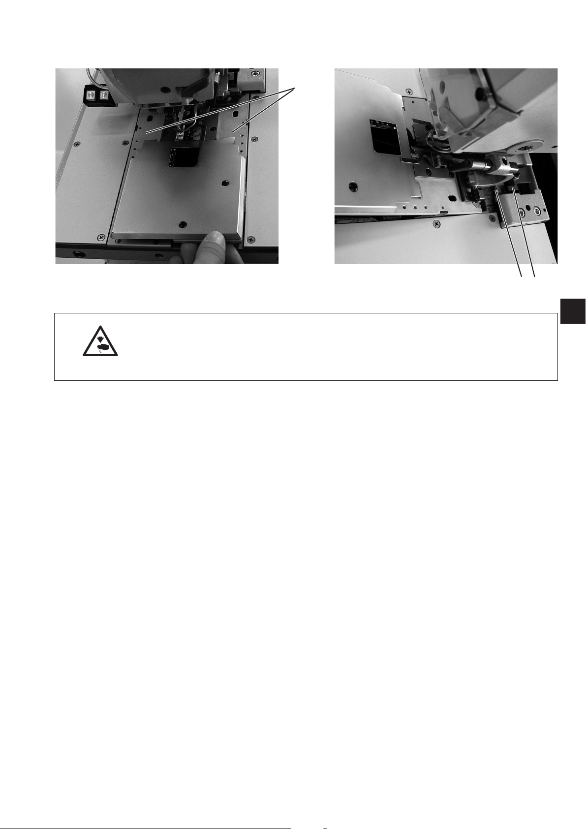
3.2 Removing and replacing the clamp plates
1
Caution: danger of injury
The clamp plates 1 must be removed and replaced with the machine
switched off or in the “firm hold” position. Inadvertently operating the
pedal with the main switch turned on may lead to damage or injury.
23
1
Removing the clamp plates
–
Slightly raise the right or left (depending on the subclass) clamp
plate 1 and remove it forwards.
–
Slightly raise the other clamp plate 1 and remove it forwards.
Fitting the clamp plates
–
First fit the left or right clamp plate 1.
The pin 2 must engage in the jaws 3.
–
Then fit the second clamp plate 1.
The pin 2 must engage in the jaws 3.
11
Page 10
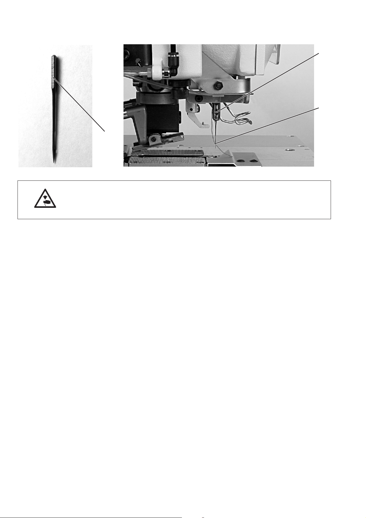
3.3 Changing the needle
1
2
3
Caution: danger of injury
The needle must be changed with the machine switched off or in the
“firm hold” position.
–
Undo screw 1.
–
Pull the needle 2 out of the needle bar.
–
Push the new needle as far as it will go into the hole in the needle
bar.
–
Align the needle 2 so that its throat points forward and the surface
3 on the needle piston to the left (in the direction of the attachment
screw 1).
–
Tighten screw 1.
12
Page 11
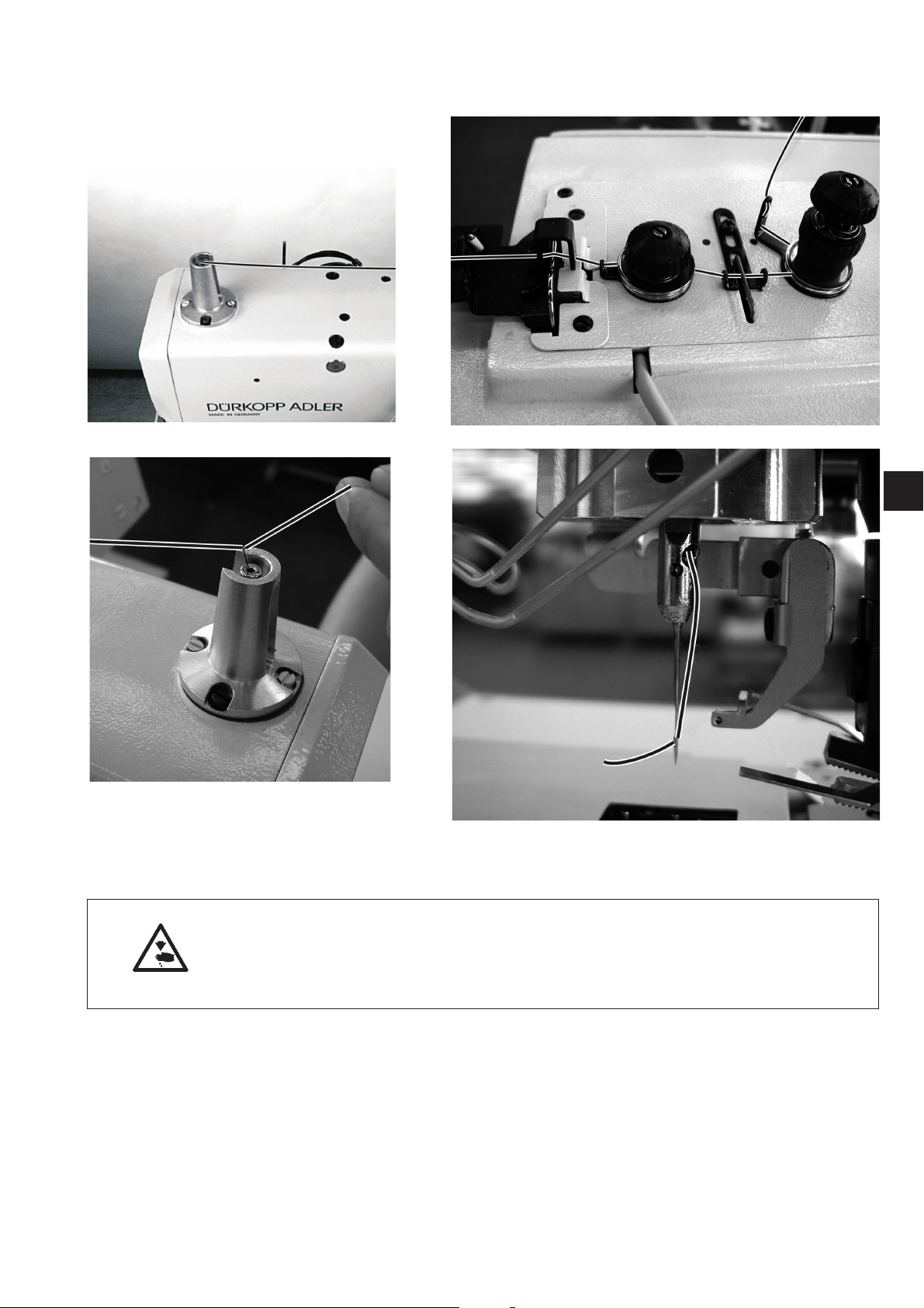
3.4 Threading the upper thread
1
Caution: danger of injury
The upper thread may only be threaded with the machine switched off
or in threading mode (see “threading mode” section).
–
Thread the upper thread as shown in the illustrations.
–
To thread the upper thread insert the threading wire (in the
accessory kit) upwards through the hollow needle bar 1 from below.
–
Place the top end of the upper thread in the hook.
–
Pull the upper thread down with the wire.
–
Thread the upper thread into the needle by drawing it forwards.
13
Page 12
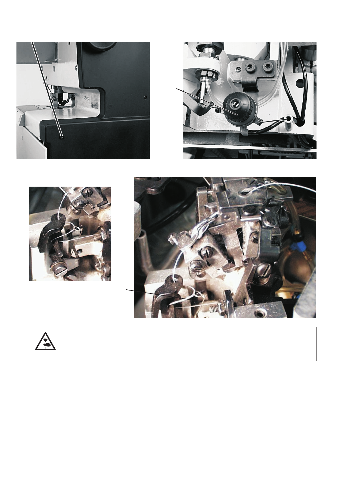
3.5 Threading the bobbin thread
1
2
Caution: danger of injury
The bobbin thread may only be threaded with the machine switched off or in
threading mode (see “threading mode” section).
The machine must be in its final position, i.e. the hook turret with
loopers must point forwards.
–
Remove clamp plates (see section 3.2).
–
Swing machine up.
–
Use the threading wires in the accessory kit to thread the bobbin
thread as shown in the illustrations.
NB: The thread must be threaded above the thread tensioner 1 and
behind the thread-tensioning spring 2.
–
Leave about 25 mm of bobbin thread hanging out of the stitch hole
in the throat plate.
–
Fit the clamp plates (see section 3.2).
14
Page 13

3.6 Threading the gimp thread (subclasses 579-121000, 579-141000 and 579-151000
only)
1
579-121000 and 579-151000 579-141000
Caution: danger of injury
The gimp thread may only be threaded with the machine switched off or in
threading mode (see “threading mode” section).
–
Thread the gimp thread as shown in the illustrations.
–
Leave about 25 mm of bobbin thread hanging out of the gimp hole
in the throat plate.
15
Page 14

4. Thread tension
4.1 Needle and bobbin-thread tension
The thread tensions depend on the type and quality of the yarn and
material. The thread tension should be the minimum at which the
appearance of the buttonhole is satisfactory.
With thin material excessive thread tensions may cause unwanted
gathering and thread breakage.
1
2
3
4
Upper-thread tension
The upper-thread tension must generally be set higher than the
bobbin-thread tension. The upper-thread tension consist of two
components the main tension for the sewing process and a residual
tension to keep the upper thread taut for the cut beneath the throat
plate.
The upper thread hanging out of the needle must be long enough to
ensure that the first stitch is securely executed. The residual tension
required to achieve this depends on the elasticity of the upper thread
used.
–
Adjust the main tension for the sewing process with the knurled
nut 1.
–
Adjust the residual tension to keep the upper thread taut when it is
cut with the sleeve 2.
If the residual tension is changed the main tension should be
corrected accordingly.
NB:
Adjusting the thread clamp 4 does not alter the upper-thread tension.
Only the clamping force can be adjusted on the thread clamp.
Bobbin-thread tension
–
Swing the head up.
–
Adjust the bobbin-thread tension with the tensioner 3.
–
Swing the head down.
16
Page 15

4.2 Bobbin-thread-tensioning spring
1
2
3
4
5
Caution: danger of injury
The thread-tensioning spring may only be adjusted with the machine
switched off or in the firm hold position.
The deflection and pre-tensioning force of the thread-tensioning spring
1 affect the bobbin-thread tension and thus the shape and purling of
the buttonhole.
Adjusting the deflection:
–
Undo screw 2.
–
Twist bracket 3.
–
Tighten screw 2.
Adjusting the pre-tension:
–
Undo screw 5.
–
Twist bracket 4.
–
Tighten screw 5.
1
17
Page 16

5. Changing the cutting blocks
1
2
The cut length can be changed by switching cutting blocks.
Caution: danger of injury
Cutting blocks may only be switched with the machine switched off or
in the firm hold position.
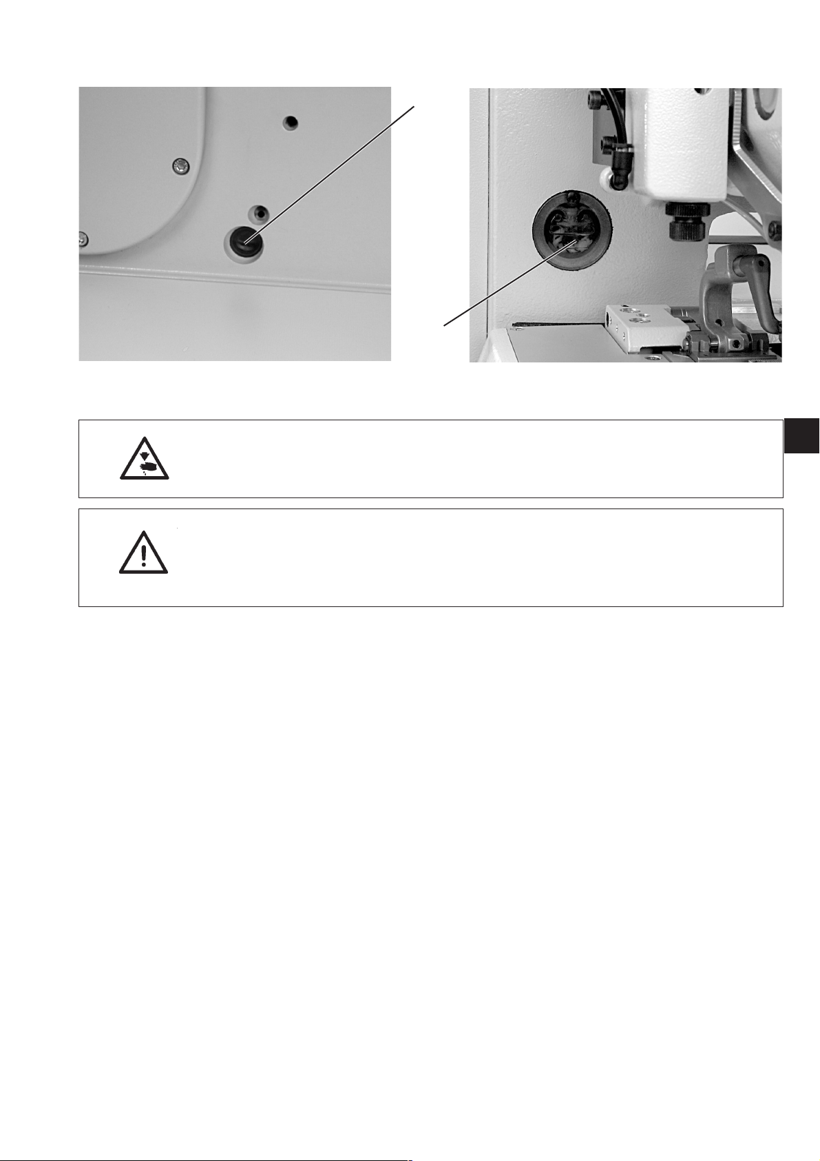
Removing the cutting-block holder
–
Remove clamp plates (see section 3.2).
–
Press button 1.
–
Pull the cutting-block holder 2 downwards and remove.
Fitting the cutting-block holder
–
Press button 1.
–
Insert the cutting-block holder in the cutting-block mounting.
–
Release button 1.
–
Check that the cutting-block holder is firmly seated in its mounting.
–
Fit clamp plates (see section 3.2).
18
Page 17

6. Spreading the workpiece
Where cutting precedes sewing the incision opens to enable the
piercing needle to sew the left and right seam rows cleanly without
piercing the cut edge of the material.
On machines where cutting follows sewing the material is kept taut for
the sewing process.
A spread of 1.5 mm is normally sufficient.
The workpiece is spread just before sewing begins. The clamp plates
are forced apart by the two pins 1.
The left and right sides must be evenly adjusted so that both clamp
plates execute an equal lateral movement.
1
2
1
3
1
7. Hand switches
Caution: danger of injury
The material spread must only be adjusted with the machine switched
off or in the firm hold position.
Adjustment
The stop screws 2 can be reached through the holes 3 on both sides of
the machine with an Allen key.
–
Adjust the stop screws on both sides so that the required spread is
achieved.
The hand switch controls the clamps and initiate the sewing process.
Their function depends on the service-menu setting (see Servicing
instructions).
Setting 1:
–
button 1: opens and closes the clamps
–
button 2: initiates the sewing process provided the clamps are
closed.
Setting 2:
–
button 1: opens and closes the clamps
–
button 2: lowers the clamps if they are not already lowered. The
sewing process begins.
19
Page 18

8. Switching on - Switching off - Firm hold
12
8.1 Switching on
–
The sewing-drive switch 1 must be in position 1.
–
Turn on the main switch 2.
The Dürkopp Adler logo briefly appears.
The opening screen appears.
8.2 Switching off
8.3 Firm hold
–
Turn off the main switch 2.
All drives and the controller are immediately disconnected from the
power supply.
Before any work is carried out on the machine it must be switched off
or the firm-hold mode activated.
Push the pedal back.
–
Turn switch 1 to position “0".
The machine is in firm-hold mode.
This message appears, flashing.
The sewing drive is disconnected from the mains.
The buttonhole blade is switched off.
–
To resume the sewing process proceed as follows:
Turn switch 1 to position “1".
After a short pause the machine is again ready for operation. The
sewing process is resumed at the point where firm hold was
activated.
If the symbol appears in reverse, firm hold was switched on before the
pedal was pushed back.
To clear proceed as follows:
–
Turn switch 1 to position “1".
–
Push the pedal back.
–
Turn switch 1 to position “0".
The machine is in firm-hold mode.
20
Page 19

8.4 Switching threading mode on and off
Caution: danger of injury
For threading either the machine must be switched off or threading
mode must be activated.
–
Push the pedal back.
The hook turret is rotated to the optimum threading position.
The thread tensioners are opened.
–
Turn switch 1 to position “0".
This message appears.
–
Thread the upper or bobbin thread.
–
Turn switch 1 to position “I”.
After a short pause the machine switches to sewing mode.
The machine is ready for operation.
9. Controller
1
9.1 General
The class 579 buttonhole machine is equipped with a programmable
controller. Up to 50 different buttonholes can be defined. The
buttonholes can be programmed in up to 25 sequences. Each
sequence can contain up to 5 buttonholes. During operation the
machine can switch among the programmed buttonholes either
automatically or manually.
The following buttonhole shapes are available for selection:
–
buttonholes with taper tack
–
buttonholes with round tack
–
buttonholes with cross tack
–
buttonholes without tack
–
eyelets.
The various buttonhole properties such as length and eye shape can
be set for all shapes.
CAUTION:
Not all buttonhole shapes and variants can be sewn on every subclass
and with every sewing apparatus.
21
Page 20

9.2 Operating the controller
Display
Entry field
OK key
key function
ïð In the main menu: switch from one buttonhole program
to another
If an entry field is activated:
switch from one position to another.
Where functions have a number of selection possibilities:
switch from one to another, e.g. from “cut before
sewing” to “cut after sewing” or “no cut ”.
òñ If no entry field is activated:
switch from one menu line to another. The selected
line appears on a dark background.
If an entry field is activated:
Increase or reduce the value of the selected position.
OK-key If no entry field is activated:
activate the entry field. The value can be changed with the
“ñ” and “ò” keys.
If an entry field is activated:
the value set is accepted.
ESC If an entry field is activated:
an entry is abandoned. The previous value is retained.
If no entry field is activated:
the menu is closed or the clamp opened.
P The controller switches to buttonhole-programming mode.
Buttonhole parameters can be changed in this mode.
S The controller switches to buttonhole sequence mode.
Buttonhole sequences can be changed
in this mode.
F The controller switches to the service menu. Access to the
service menu requires the entry of a code number.
RST Close clamps and initiate the sewing process.
During operation:
stop and re-start the sewing process.
22
Page 21

9.3 Changing parameter values
9.3.1 Numerical values
Numerical values can be changed in the following way:
–
–
–
–
–
Use the ñ and ò cursor keys to select the line containing the value
you wish to change.
Press the enter key.
The cursor flashes under one digit of the numerical value.
Use the ï and ð cursor keys to move from one digit to another.
Use the ñ and ò cursor keys to increase or reduce the value of the
selected digit.
Where parameters are limited to certain values (e.g. eye shape),
pressing the ñ and ò cursor keys displays another possible
parameter value.
Press OK.
The set value is accepted.
If the set value is not to be accepted, press “ESC”.
The original value is restored.
9.3.2 Selecting a parameter
Some parameters allow selection among a number of possibilities.
These parameters can be changed in the following way:
–
Use the ñ and ò cursor keys to select the line containing the
parameter or value to be changed.
–
Press OK.
–
Use the ñ and ò cursor keys to switch from one possibility to another.
The selected symbol appears in the display.
Exception:
to switch cut mode use the ï and ð cursor keys.
–
Press the enter key.
The set parameter or value is accepted.
–
If the set parameter or value is not to be accepted, press “ESC”.
The original parameter or value is restored.
1
23
Page 22

9.4 Sewing process
9.4.1 Switching on
Buttonhole shape
Number of
buttonhole
sequence
Buttonhole
sequence
Rotation speed
buttonhole length
cut mode
Piece counter
–
Turn on the main switch .
The Dürkopp Adler logo briefly appears..
–
The main screen appears.
–
Press the “RST” key on the operating panel.
The machine moves to the insertion position and is ready for
operation.
A sketch of the buttonhole to be sewn first appears in the left half
of the display.
9.4.2 Sequence mode and single-button mode
Depending on the service-menu setting either sequence mode or
single-button mode is available.
9.4.2.1 Selecting a sequence (sequence mode)
After switch-on the top line in the display appears on a dark
background. The last sewing sequence used is selected.
Selecting a different sequence
–
Press OK.
–
Use the ñ and ò cursor keys to switch from one sequence to
another.
9.4.2.2 Selecting a buttonhole (single-buttonhole mode)
If single-button mode is set in the service menu, no sequence can be
activated.
After switch-on the top line in the display appears on a dark
background. The last buttonhole sewn is displayed.
Selecting other buttonholes
–
Press OK.
–
Use the ñ and ò cursor keys to switch from one buttonhole to
another.
24
Page 23
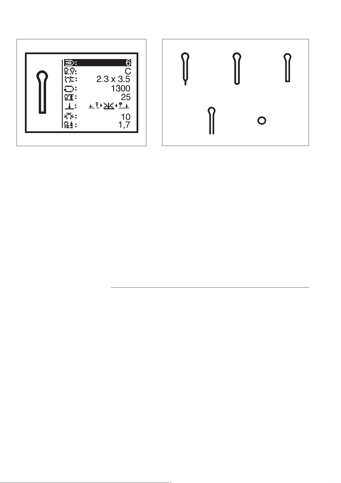
9.4.3 Changing buttonhole parameters
The main parameters of the buttonhole are displayed on the main
screen.
Changing the parameters
–
Use the ñ and ò cursor keys to select the line containing the
parameter to be changed.
–
Press OK.
–
Change the parameter value.
–
Press enter to accept the changed value.
–
If the new value is not to be accepted, press “ESC”.
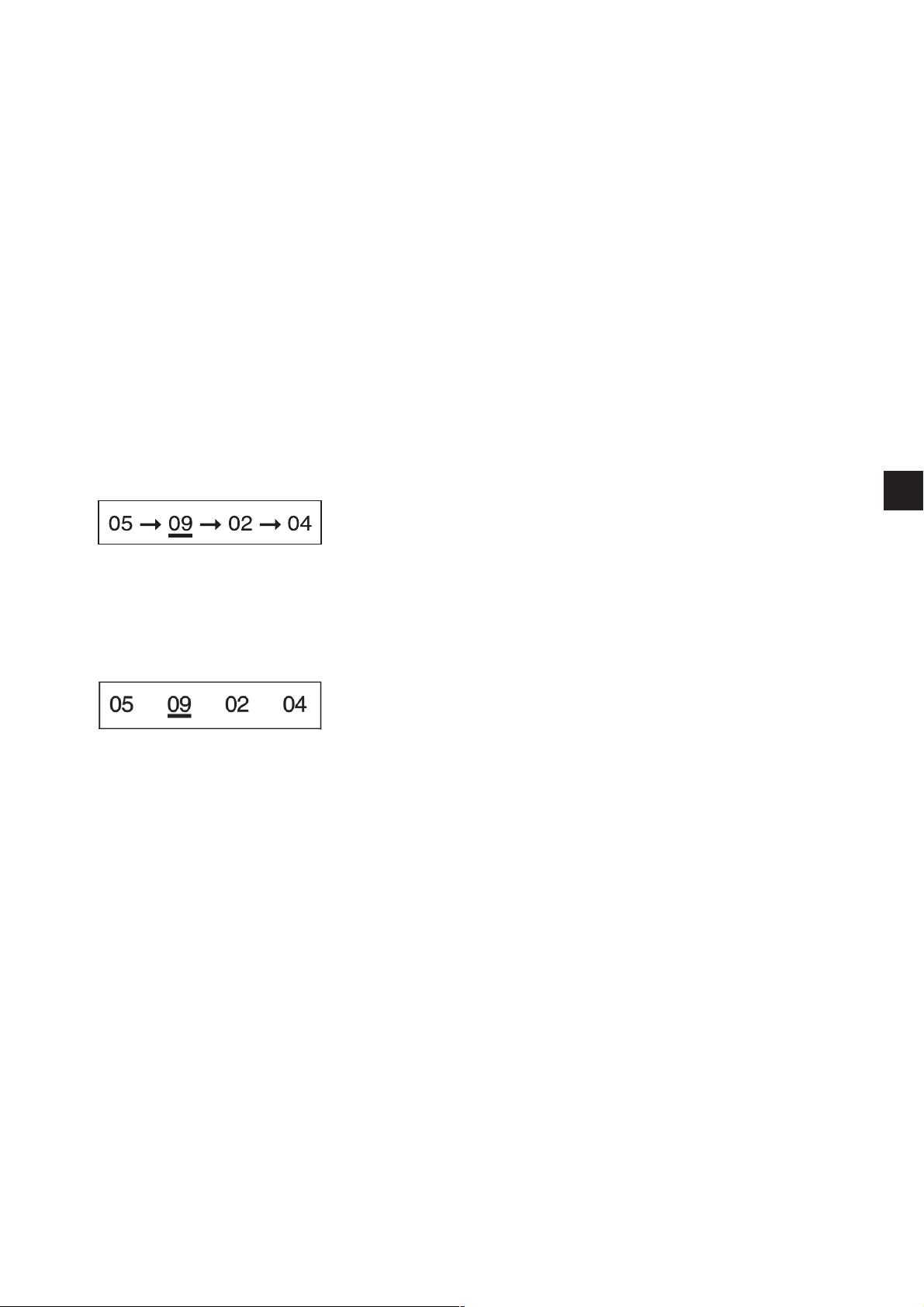
9.4.4 Automatic or manual operation (can only be set in sequence mode)
Depending on the setting the machine operates either manually or
automatically.
Automatic operation
Arrows are displayed between the buttonhole shapes in the sequence
displayed.
After a buttonhole has been completed the controller switches
automatically to the next shape. After the last buttonhole has been
completed the controller switches back to the first buttonhole in the
sequence.
The current buttonhole is marked with a bar.
1
Manual operation
No arrows are displayed between the buttonhole shapes in the
sequence displayed.
The controller does not switch automatically between the buttonhole
shapes.
The current buttonhole is marked with a bar.
Switching between automatic and manual operation
–
Use the ñ and ò cursor keys to select the line containing the
current sequence.
–
Press OK.
–
Use the ñ and ò cursor keys to switch between the two operating
modes.
The arrows between the buttonhole shapes appear and disappear
accordingly.
Selecting the next buttonhole to be sewn in a sequence
If the sewing menu is shown in the display, you can switch from one
programmed buttonhole to another at any time.
–
Press the ï or ð cursor key.
The next or previous buttonhole shape in the sequence displayed
is selected.
25
Page 24

9.5 Sewing
0
1
2
The sewing process can be controlled with the pedal, the hand
switches or the “RST” and “ESC” keys on the operating panel.
In automatic operation the machine moves to the new insertion position
after each sewing process (sequence mode).
In manual operation it moves to the insertion position of the current
buttonhole (sequence and single-button mode).
Sewing with the pedal
–
Push the pedal back.
The machine moves to the insertion position.
–
Insert the material.
–
Push the pedal forwards to position 1.
The clamps close.
0
R
Releasing the pedal opens them again.
The pedal moves to its rest position.
–
Push the pedal down to position 2
The sewing process is initiated.
–
To carry out another sewing process the pedal must be returned to
its starting (rest) position.
Sewing with the operating-panel keys
–
For the first operation after switch-on press the “RST” key if any
parameters have been changed or another buttonhole shape has
been selected manually.
The machine moves to its starting position and from there to the
insertion position.
–
If you wish the machine to move to its starting position, press the
“ESC” key.
–
Insert the material.
–
Press the “RST” key once.
The clamps close.
–
If you wish the clamps to re-open, Press the “ESC” key.
–
If you wish the sewing process to be initiated, press the “RST” key
again.
After the sewing process the machine returns to the insertion
position.
26
12
Removing material after sewing (subclass 579-151000)
–
Sever the upper gimp, pulling it a little if necessary. The material
can be moved on or removed.
–
To remove the material pass the bobbin thread and lower gimp
under thread clamp 2. Pull both threads from right to left along
blade 1.
The threads are severed.
Page 25

9.5.1 Fast switch-off
The comprehensive safety system on the 579 contains various features
enabling it to be halted immediately in the event of incorrect operation,
needle breakage, thread breakage etc.
–
Push the pedal backwards beyond the rest position, press the
“RST” key or press button 1 or 2 on the hand switches.
The machine halts with the needle raised.
–
If you wish sewing to be resumed, push the pedal forwards, press
the “RST” key again or press button 2 on the hand switches.
The sewing process resumes.
–
If you wish to remove the material, push the pedal back, press the
“ESC” key on the operating panel or press button 1 on the hand
switches.
1
27
Page 26
9.6 Changing a buttonhole program
A
D E
Up to 50 different buttonholes can be programmed in the buttonhole
programming menu.
The various parameters of each buttonhole shape can be changed.
A sketch of the current buttonhole shape is shown in the left half of the display.
If the ñ and ò cursor keys are pressed to switch from one buttonhole
parameter to another in the right half, the current measurement is always
highlighted in the sketch.
If not all adjustable parameters fit in the display, the content can be
shifted up or down by pressing the cursor keys at the top or bottom of
the display.
–
Press “P”.
The controller switches to the buttonhole programming menu.
–
Press “S” to program or alter a sequence.
–
To leave the menu press the “ESC” key.
B
C
The following buttonholes with their parameters can be programmed in
the buttonhole programming menu.
Type Buttonhole shape Adjustable parameters
A taper tack eye shape, speed, buttonhole length,
cut, cut-position correction,
speed in the eye, stitch distance, throw
width in the eye, intermediate fabric
taper tack overlap, taper tack length
B round tack eye shape, speed, buttonhole length,
cut, cut-position correction,
stitch count in the eye, stitch distance,
throw width in the eye, intermediate fabric
overlap, number of stitches in the
round tack
C cross tack eye shape, speed, buttonhole length,
cut, cut-position correction,
stitch count in the eye, stitch distance, throw
width in the eye, intermediate fabric
cross tack length, stitch distance in the cross
tack, lateral cross tack length, seam extension
D without tack eye shape, speed, buttonhole length,
cut, cut-position correction,
stitch count in the eye, stitch distance,
throw width in the eye, intermediate fabric
E eyelet speed, eyelet diameter,
cut, stitch count in the eyelet,
throw width, overlap.
28
Page 27

Measurement / Repère
a stitch distance
d eyelet diameter
kl taper tack length
l length
qb cross tack length
ql lateral cross tack position
qs stitch distance in the cross tack
qv seam extension
x eye shape
y eye shape
NB:
Not all symbols are displayed, only the ones that are important for the
pertinent buttonhole type.
Eyelets and their parameters can only be changed with sewing
apparatus E110, E111, E510 and E511.
Symbol Parameter Meaning
Buttonhole number The number of the buttonhole to be processed.
If a new buttonhole is selected, a * appears
before its number.
Buttonhole type Buttonhole types A to E are available,
depending on the subclass (see also page 27).
Eye shape The external dimensions (x, y) of the eye.
Buttonholes without eyes have dimensions
0.0x0.0. Which buttonhole shapes are possible
depends on the cutting mode set.
When switching from buttonholes with eyes to
buttonholes without eyes the stitch count in the
eye is set to 7. When switching from
buttonholes without eyes to buttonholes with
eyes the stitch count in the eye is set to 10.
The buttonhole display in the left half of the
display alters accordingly.
Speed The speed of the machine.
Length The buttonhole length from the upper end of
the eye up to the beginning of the tack
(measurement l).
Cut
12 3
The following parameters are available:
- cut before sewing (item 1)
- no cut (item 2)
- cut after sewing (item 3).
1
Cut-position
correction
Stitch count in the
eye
Stitch distance The distance between stitches within the side
Throw width in the
side
The distance by which the cut of the blade is
moved lengthwise. Values from -0.3 to +0.3
can be set.
The number of stitches sewn by the machine in
the eye.
of the buttonhole (measurement a).
The value must be between 0.5 and 2 mm.
This parameter changes the throw width in the
side of the buttonhole.
29
Page 28

Symbol Parameter Meaning
Intermediate fabric This parameter changes the
intermediate-fabric type.
Taper tack length In buttonholes with taper tacks, the length from
the tip of the taper to the end of the taper
(measurement kl). The minimum taper tack
length is 2 mm.
When changing the buttonhole length please
ensure that the maximum sewing length is not
exceeded. This can occur with taper-tack
buttonholes as the length of the taper tack
forms part of the sewing length.
When the buttonhole length is increased the
taper tack length is thus automatically adjusted
accordingly.
Taper tack overlap The distance between the two sides in the
straight section of the taper tack. When it is
0.0 mm one side is directly above the other.
Overlap In round tacks and eyelets the overlap can be
adjusted.
Number of stitches
in the round tack
Throw width in the
cross tack
Cross tack length In buttonholes with cross tacks, the overall
Stitch distance in
the cross tack
Lateral cross tack
position
Seam extension In buttonholes with cross tacks the distance
Eyelet diameter The diameter of the eyelet (measurement d).
Stitch count in the
eyelet
In round tack buttonholes, the number of
stitches in the round tack. 4, 6, 8 or 10 stitches
are possible.
This parameter changes the throw width in the
cross tack.
length of the cross tack (measurement qb).
In buttonholes with cross tacks, the gap
between stitches in the cross tack
(measurement qs).
In buttonholes with cross tacks, the position of
the cross tack with respect to the
centre(measurement ql).
- = cross tack left
+ = cross tack right
between the buttonhole side and the cross tack
can be set.
The number of stitches in the eyelet.
30
Page 29
9.7 Buttonhole sequence
The 579 controller can be programmed with up to 25 sequences of
buttonhole shapes. Each sequence can contain up to 5 buttonholes.
–
Press “S”.
The controller switches to the buttonhole-sequence programming
menu.
–
To program or alter a buttonhole shape press “P”.
–
To leave this menu press the “ESC” key.
1
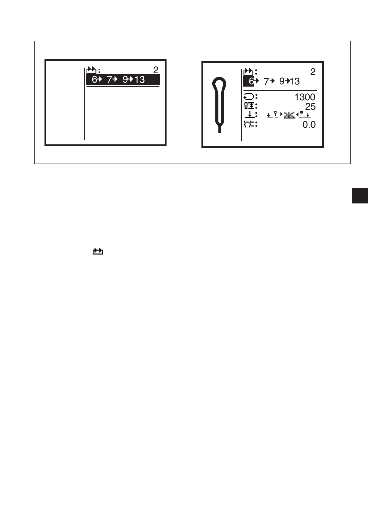
9.7.1 Selecting a buttonhole sequence
–
The number of the selected sequence is displayed behind this
symbol.
The sequence belonging to the sequence number is displayed in
the line below.
–
To switch to another sequence select the top menu line.
–
Press the enter key.
–
Use the ñ and ò cursor keys to select a different sequence.
–
When a new sequence is created a “*” appears before the
sequence number (setting for buttonhole shape of sequence: 1)
9.7.2 Changing the buttonhole sequence
Appending a buttonhole
–
Use the ñ and ò cursor keys to select a buttonhole sequence.
–
Press the enter key.
–
Within the buttonhole sequence use the ð cursor key to select the
point behind the last buttonhole.
“0" appears as the buttonhole shape.
–
Use the ñ and ò cursor keys to select the number of the required
buttonhole shape.
Deleting a buttonhole
–
Use the ñ and ò cursor keys to select a buttonhole sequence.
–
Press the enter key.
–
Within the buttonhole sequence use the ï and ð cursor keys to
select the buttonhole to be deleted.
–
Use the ñ and ò cursor keys to set buttonhole shape “0".
–
Press the enter key.
The selected buttonhole is deleted. Any subsequent buttonholes
move up one place.
31
Page 30

9.8 Piece counter
General
The 579 machine is equipped with a piece counter.
The piece counter counts the number of buttonholes sewn, not the
number of buttonhole sequences sewn. The current piece-counter
value is displayed behind the “Σ” symbol.
Switching the machine off does not affect the piece-counter value. The
piece counter counts up to a maximum of 65000 buttonholes. When
this value is exceeded, counting begins again at 0.
Resetting the piece counter
–
In the sewing menu use the ñ and ò cursor keys to select the
bottom line.
–
Press enter twice.
The piece-counter value is reset to 0.
32
Page 31

9.9 Buttonhole and sequence programming: a brief description
9.9.1 Selecting a buttonhole number
–
Push the pedal back:
the cloth carrier plate and hook turret move to their starting
positions
–
Press “P”:
The display switches from sewing mode to buttonhole programming
mode.
In this mode the buttonhole parameters can be changed.
–
The buttonhole number line appears on a dark background.
–
If you wish to change the buttonhole displayed, skip to
section 9.9.2.
–
If you wish to change a buttonhole that is not displayed or program
a new buttonhole, press OK.
–
Use the ñ and ò keys to display buttonholes already programmed.
–
If a new buttonhole is selected, a “*” appears before the buttonhole
number.
–
Select a buttonhole number and press OK to confirm.
9.9.2 Entering parameters
–
Use the ñ and ò keys to select the parameter to be changed.
–
The line containing the selected parameter appears on a dark
background.
–
Press OK.
The cursor flashes under the value of the selected parameter and
only the symbol appears on a dark background.
–
Use the ñ and ò keys to set the required value.
–
Use the ï and ð keys to change the cutting mode.
–
Press OK.
The set value is accepted.
–
If you do not wish to accept the changed value, press the “ESC”
key.
The original value is restored.
–
Use the ñ and ò keys to select and change further parameters.
–
Press the “ESC” key to leave buttonhole programming mode.
The machine is now in sewing mode and thus ready for operation.
1
33
Page 32

9.10 Setting buttonhole sequences: a brief description
9.10.1 Selecting a buttonhole sequence
–
Push the pedal back:
the cloth carrier plate and hook turret move to their starting
positions.
–
Press “S”.
The display switches from sewing mode to sequence mode:
in this mode sequences can be programmed.
The line sequence number appears on a dark background.
–
If you wish to change the sequence displayed, skip to
section 9.10.2.
–
If you wish to change a sequence that is not displayed or program
a new sequence, press OK.
–
Use the ñ and ò keys to display sequences already programmed.
–
If a new sequence is selected a * appears before the sequence
number.
–
Select a sequence number and press OK.
9.10.2 Changing a sequence
–
Use the ò key to select the line containing the buttonhole
sequence and press OK.
Now the buttonhole sequence can be changed.
–
Use the ñ and ò keys to select the buttonhole number be changed.
If you wish to delete a buttonhole from the sequence, select
buttonhole number 0.
–
Use the ï and ð keys to select the column containing the
buttonhole number to be changed.
–
When programming is complete press OK.
–
If the changed sequence is not to be saved, press the “ESC” key.
The original sequence is restored.
–
Pressing the “ESC” key leaves sequence mode. The machine is
now in sewing mode and thus ready for operation.
34
Page 33

10. Error messages
10.1 Pressure monitor
10.2 Firm hold
The pressure monitor monitors the pressure of the air supply. If the
pressure is inadequate this warning message appears in the display.
Fault rectification
–
Switch the machine off.
–
Ensure that the air pressure is adequate.
–
Switch the machine on again.
When the machine is in firm hold mode this warning message appears
in the display.
10.3 Error messages
If an error or fault occurs, a window containing an error code appears.
Error messages are described in the Servicing instructions.
10.4 Needle not in starting position
If the needle is not in its upper starting position when sewing begins,
appears this message appears.
Rectification
–
Turn the handwheel until the message disappears.
10.5 Handwheel turned manually
If the machine is halted during operation and the handwheel turned,
this symbol appears when it is restarted.
The current sewing process must be abandoned.
1
10.6 Seing-start side not correct
If when sewing begins the needle is about to execute the right needle
insertion on subclasses 121, 141 and 151 (or the left needle insertion
on subclass -112), this warning message appears.
To clear the error turn the handwheel until the message disappears.
If the warning message appears straight after switch-on, the RST key
must be pressed when the message has disappeared.
The machine moves to the starting position.
35
Page 34

11. Maintenance
11.1 Cleaning
Caution: danger of injury
Maintenance work may only be carried out with the machine switched
off.
The utmost care must be taken when carrying out maintenance work
that requires the machine to be running.
A clean machine is a trouble-free machine.
Daily cleaning:
–
The looper, thread trimmer, throat plate and sewing head areas
must be cleansed daily of lint, pieces of thread and other debris.
1
2
3
–
Check the water level in the pressure regulator every day.
The water level must not rise to the level of the filter cartridge 2.
After screwing in the drain screw 3 blast water under pressure out
of the water separator.
36
Page 35
11.2 Lubrication
1
2
Check the oil level in oil reservoirs 1 and 2 every week.
Caution: danger of injury
Oil can cause skin eruptions.
Avoid protracted contact with the skin.
In the event of contact, thoroughly wash the affected area.
CAUTION:
The handling and disposal of mineral oils is subject to legal regulation.
Deliver used oil to an authorised collection point.
Protect your environment. Take care not to spill oil.
Use only ESSO SP-NK 10 lubricating oilor an equivalent oil of the
following specification:
- viscosity at 40°C: 10 mm²/s
- flashpoint: 150° C
to top up the oil reservoirs.
This oil is available from
DÜRKOPP ADLER AGretail outlets under the following part numbers:
- 2-litre container: 9047 000013
- 5-litre container: 9047 000014
1
General
All the machine’s moving parts are lubricated by two oil reservoirs via
an oil-wick system.
No lubrication work is thus required except checking and topping up
the oil reservoirs.
37
Page 36

Notice:
38
 Loading...