

Page 1

Contents Page:
Home
Preface and General Safety Standards
Part 1: Operating Instructions cl. 577-1 1 11
1. Product description
2. Normal use
3. Technic al data
4. Operation
4.1 Threading the needle . . . . . . . . . . . . . . . . . . . . . . . . . . . . . . . . . . . . . . . . . . . 7
4.2 Winding the hook thread . . . . . . . . . . . . . . . . . . . . . . . . . . . . . . . . . . . . . . . . . 8
4.3 Inserting the bobbin . . . . . . . . . . . . . . . . . . . . . . . . . . . . . . . . . . . . . . . . . . . . 8
4.4 Changing the needle . . . . . . . . . . . . . . . . . . . . . . . . . . . . . . . . . . . . . . . . . . . 10
4.5 Lifting the sewing cage . . . . . . . . . . . . . . . . . . . . . . . . . . . . . . . . . . . . . . . . . . 11
4.6 Regulating the sewing cage pressure . . . . . . . . . . . . . . . . . . . . . . . . . . . . . . . . . . 11
4.7 Setting the buttonhole length . . . . . . . . . . . . . . . . . . . . . . . . . . . . . . . . . . . . . . . 12
4.8 Setting the number of stitches . . . . . . . . . . . . . . . . . . . . . . . . . . . . . . . . . . . . . . 13
4.9 Changing and adjusting the knife . . . . . . . . . . . . . . . . . . . . . . . . . . . . . . . . . . . . 14
4.10 Thread tension . . . . . . . . . . . . . . . . . . . . . . . . . . . . . . . . . . . . . . . . . . . . . . . 16
5. Control and control panel
5.1 General . . . . . . . . . . . . . . . . . . . . . . . . . . . . . . . . . . . . . . . . . . . . . . . . . . . 17
5.2 Keys on the control panel . . . . . . . . . . . . . . . . . . . . . . . . . . . . . . . . . . . . . . . . . 18
5.3 Changing parameter values . . . . . . . . . . . . . . . . . . . . . . . . . . . . . . . . . . . . . . . 19
. . . . . . . . . . . . . . . . . . . . . . . . . . . . . . . . . . . . . . . . . . . . . . . . 5
. . . . . . . . . . . . . . . . . . . . . . . . . . . . . . . . . . . . . . . . . . . 5
. . . . . . . . . . . . . . . . . . . . . . . . . . . . . . . . . . . . . . . . . . . . . . 6
6. Sewing
6.1 Normal sewing cycle . . . . . . . . . . . . . . . . . . . . . . . . . . . . . . . . . . . . . . . . . . . 22
6.2 Interruption of th4e sewing cycle . . . . . . . . . . . . . . . . . . . . . . . . . . . . . . . . . . . . . 22
6.3 Monitoring the hook thread by counting the buttonholes . . . . . . . . . . . . . . . . . . . . . . . . 23
7. Maintenance
7.1 Cleaning and checking . . . . . . . . . . . . . . . . . . . . . . . . . . . . . . . . . . . . . . . . . . 24
7.2 Lubrication . . . . . . . . . . . . . . . . . . . . . . . . . . . . . . . . . . . . . . . . . . . . . . . . . 25
8. Auxiliary equipment
. . . . . . . . . . . . . . . . . . . . . . . . . . . . . . . . . . . . . . . . . . . 26
3
Page 2
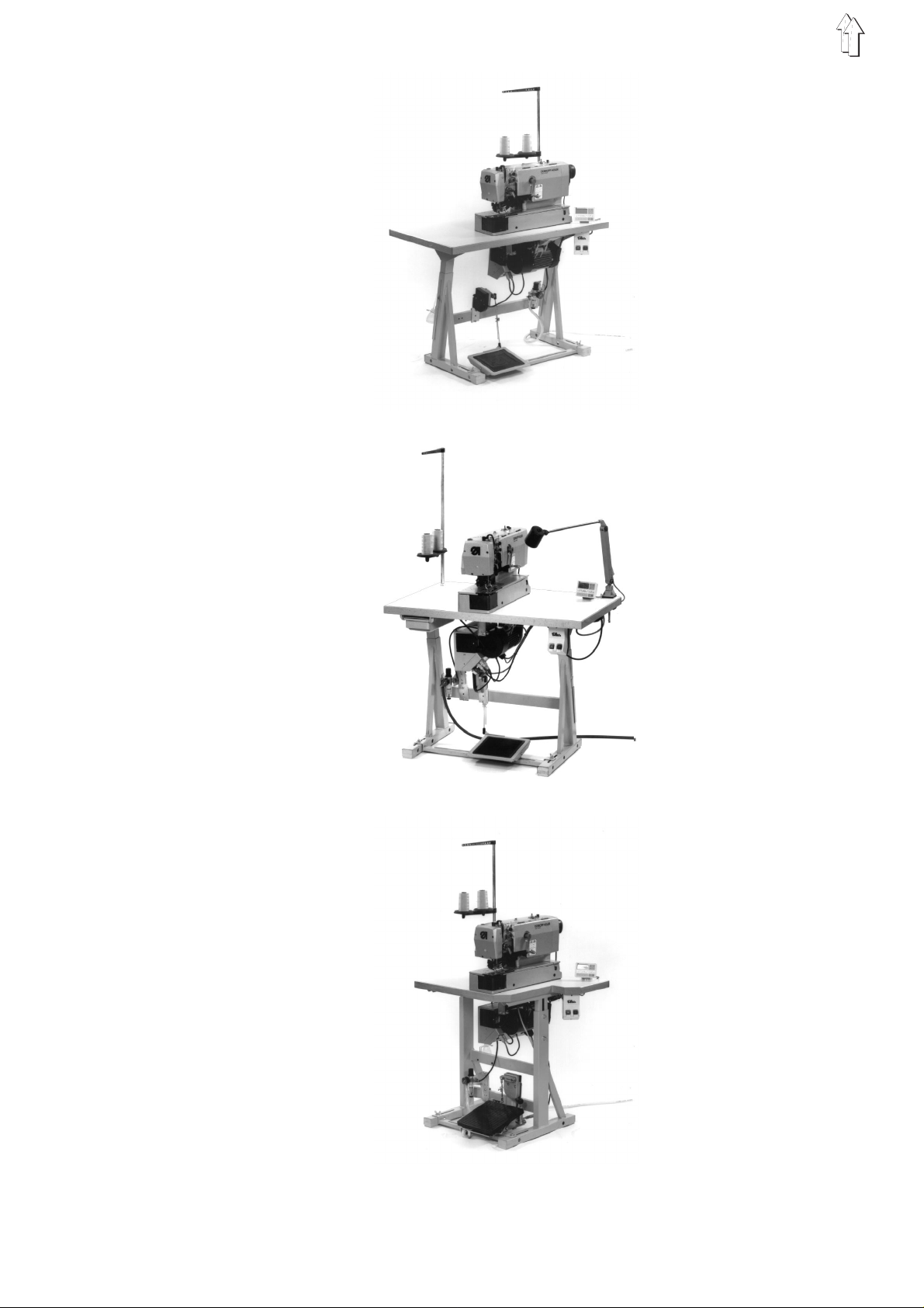
Stand set for longitudinal installation
Stand set for transversal installation
Stand set for transversal/longitudinal operation
4
Page 3

1. Product description
2. Normal use
DÜRKOPP ADLER 577-1111
The
machine with bottom and top fe ed fo r s ewing buttonhol es w i th two
straight bars.
Normal sewing mo de :
During the sewi n g p roc e s s th e f ab r ic fa c e ( t he fa c e se en ) ) i s up .
The machine c a n b e supplied in thre e i n s ta l l at i on v ari a nt s ( see on the
left ).
is an automatic double lockstitch
The automatic sewing machine
designed for s ew i ng l igh t t o m i dd l e-h ea v y we i gh t m at eri a l , a s us e d i n
the apparel industry.
Such materi al co ns i s t s ge ne ral l y o f t ex t i l e o r s y nt he ti c f i bre s .
Furthermore, the machine lends itself for producing so-called technical
seams. In this case, the user must estimate any possible dangers
(contact dürkopp adler ag for help), Technical seams are seldom, but
they may be very versatile. Proper safety precautions, depending on
the result of s uc h an estimation, mus t b e t ak e n. G en er a ll y, only dry
material sh ou l d b e sewn on this machin e. An d th e ma te r ial s ho ul d not
exceeded the thickness of
4 mm
when compress e d b y th e l o we r ed sew i ng fo ot .
The material should not contain any hard objects, because otherwise it
would be necess a ry to pr o te ct t he ey e s du r i ng th e se wi n g p roc e s s..
For the time b ei n g, no s uch eye guard is av a i l ab le. The seams are
produced gene r al ly w i th th r ea ds u p t o 6 5/ 2 Nm ( cotton-cov e red
synthetic threads or synthetic threads ) Before using any other threads
it is necessary, also in this case, to estimate the consequential
dangers and to take, if necessary, the respective safety measures.
This automat i c sewing unit shou l d b e i n s ta l led and operated onl y in
dry and proper rooms. Otherwise, further precautions (to convene)
may be needed , ( s i e he E N 6 02 04 - 3-1:1990 ). We.manuf ac t ur e rs of
industrial sewing machines, assume, that our machines will be
operated at le as t by a we l l trained staff, know i ng al l u s ua l con tr o l s an d
any possible dangers.
DÜRKOPP ADLER 577-1111
has been
5
Page 4

3. T echnical data
Machine head s: Class 577-1111
Needle system: System 265, needle point slightly rounded off
Needle thi ck ne s s : 70 - 100, Standard 80
Threads: Synthetic threads, and cotton-coated
synthetic threads
Up to 65/2 Nm
Stitch type: Double lockstitch
Speed: up to. 4000 rpm ( a dj u s ta bl e )
Number of stitches
Per seam pattern: 76 - 510
Buttonhol e length: 10 - 48 mm
Buttonhol e w i dt h: 0 - 6 mm
Cut length: max. 38 mm
Motor type: EFKA DC1600/DA82GL
Nominal pe rfo r ma nc e : 0,75 kW
Speed: 4000 U/min
Service pressure: 6 bar
Air consumption: about 4 NL per working cycle
Nominal vol t ag e: 1 ~ 230 V, 50/60 Hz
1~ 190 - 240 V, 50/60 Hz
Dimensions:
Longitudinal stand: 1060 x 620 x 1250 mm ( L x B x H )
Longitudinal/transversal
stand: 800 x 650 x 1250 mm ( L x B x H )
(Machine hea d w i th ou t s t an d: 180 x 600 x 450)
Working level : 750...895 mm ( Table top )
Weight: ca. 135 kg ( wi t h s t an d )
Rated noise level:
Lc = .... dB (A)
6
Page 5
4. Operation
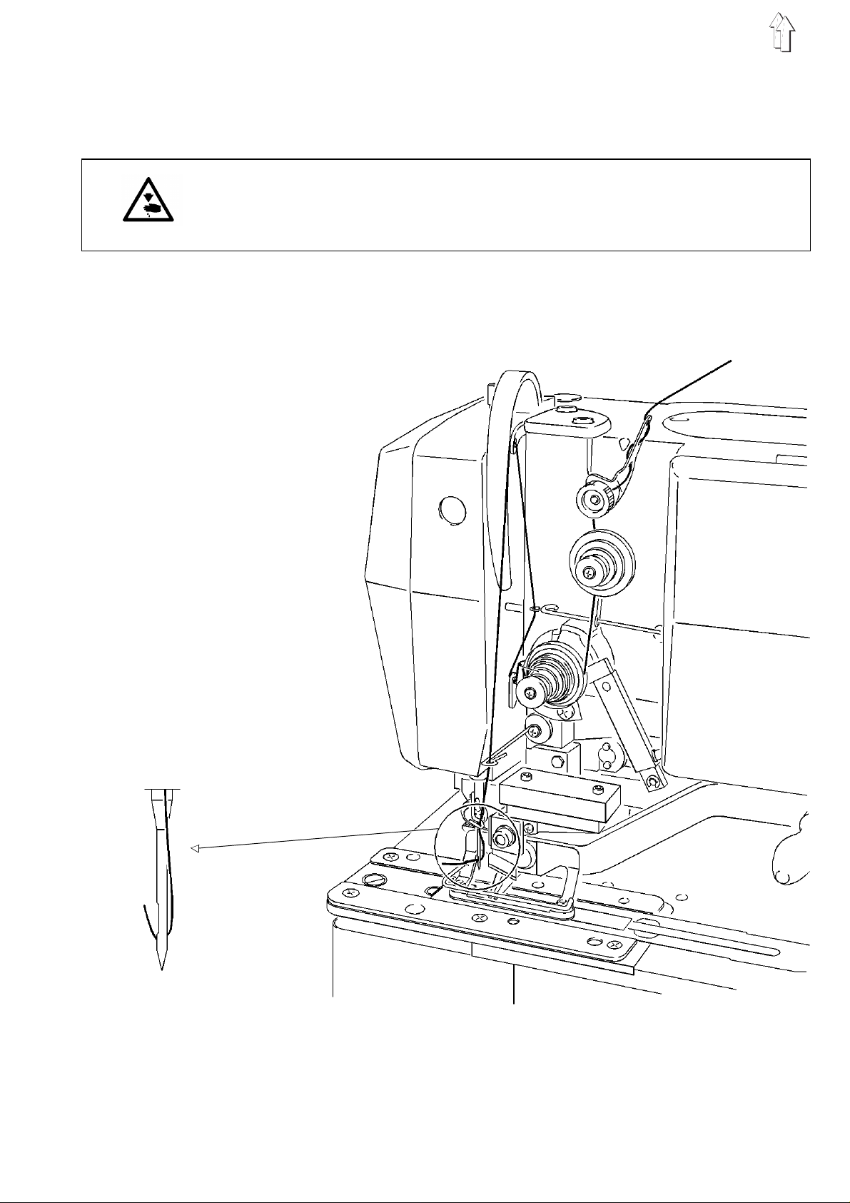
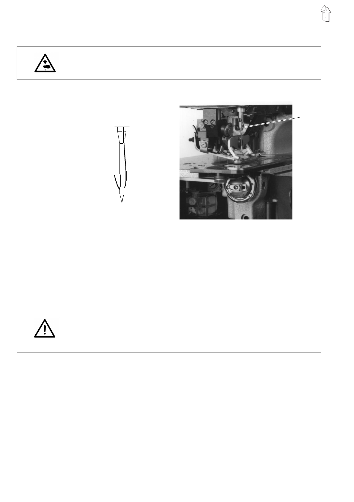
4.1 Threading the needle
CAUTION: DANGER OF ACCIDEN T S !
Turn off main switch!
Switch off the machine before threading the needle.
–
Thread then needle according to the illustration.
7
Page 6
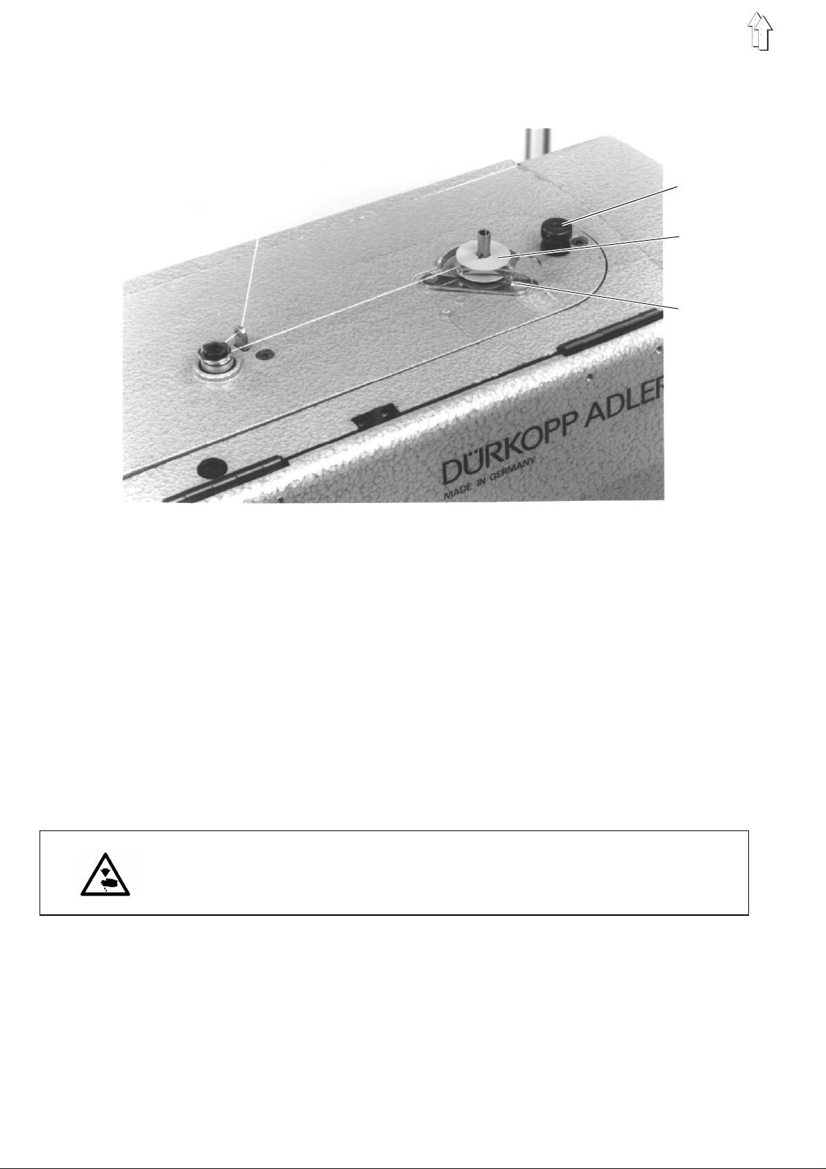
4.2 Winding the hook thread
3
1
2
4.3 Inserting the bobbin
–
Slip the ree l on to i ts st and.
–
Thread the hook according to the illustration.
–
Slip the bobb i n o nto the bobbin w inder 1 .
–
Wind the hook thread clockwise about 5 times around the bobbin
core.
–
Swing bobbin winder lever 2 towards the bobbin and let i t s na p.
–
The thread will be wound during the sewing process.
–
The bobbin wi nd er l e v er 2 will stop the winding process as soon as
the bobbin is full.
–
Following the winding process, tear off the bobbin thread at the
thread clam p 3.
CAUTION: DANGER OF ACCIDENTS !
Turn off main switch!
Switch off th e m ac h ine before changing the bobbin!
Removing empty bobbin.
–
Open hook space cover 4.
–
Lift the bow 5 and remove bobbi n c ase to p t og et he r wit h t he
bobbin.
–
Remove the em pt y bo bb i n f rom the bobbin case to p.
8
Page 7
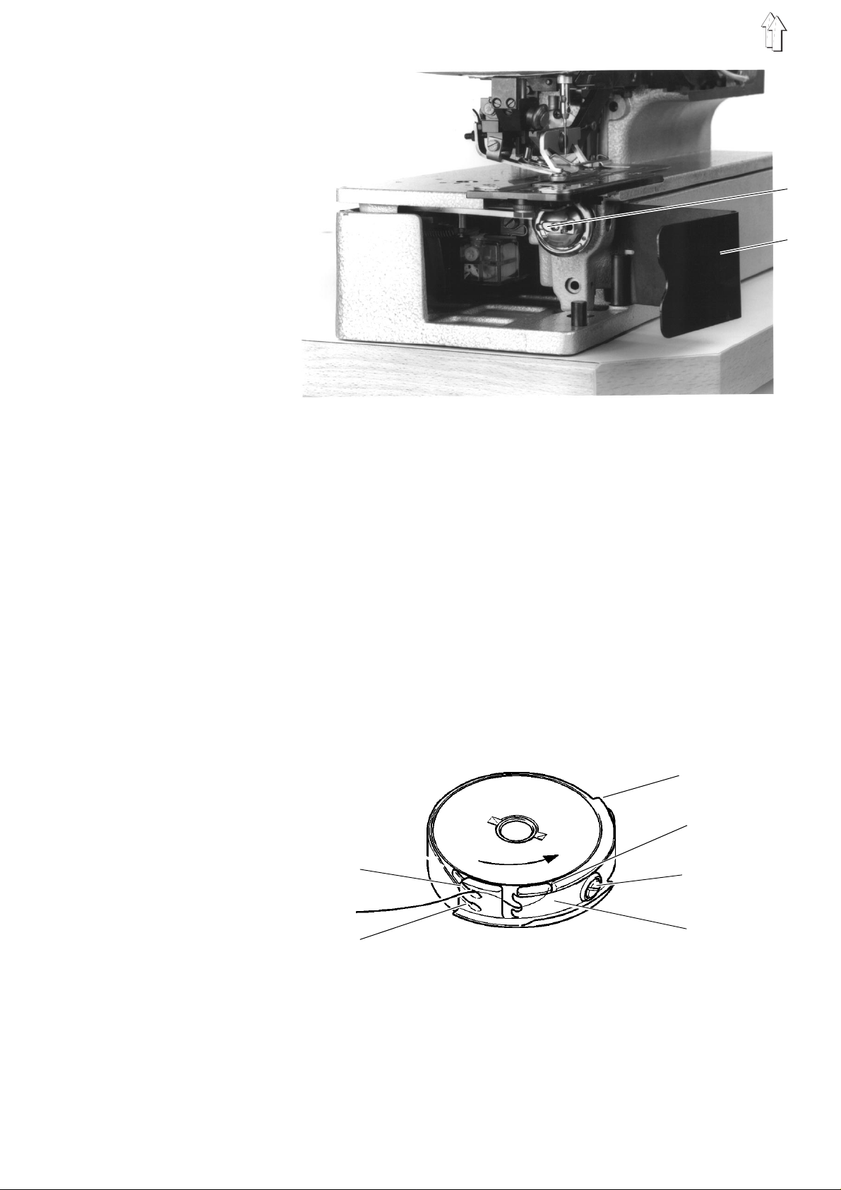
Threading the bobbin
–
Insert the full bobbin into the bobbin case top. When unwinding the
thread, the bobbin must turn clockwise.
–
Pass the hook thread through the slit 6 and under the spring 7.
–
Depending on the buttonhole to be sewn, pass the hook thread
through the slit 9 for a
advanced across the hook ba ck ) ) or through the sl i t 10 for a
buttonhole ( l e s s th rea d ) .
–
Cut then the t hr e ad , p as s e d a s de sc r i be d, by t he k nife 11.
raised
buttonhole ( more thread will be
5
4
flat
Adjusting the hook thread tension
–
Adjust the hook thread tension by turning the screw 12 so that,
when holding t he th rea d a t i t s en d, th e b ob bin c ase de s c en ds b y
its own weight.
11
6
9
12
7
10
Inserting the bobbin case top
–
Place the bo bb i n c a s e t op to ge th er w i th th e b ob bi n on to the bobbin
case bottom an d e nsu r e t ha t t he bo w 5 snaps (what you should
hear).
–
Close the bobbin space cover 4.
9
Page 8
4.4 Changing the needle
CAUTION: DANGER OF ACCIDENTS !
Turn off main switch!
Switch off th e m ac h ine before changing the needle!
1
Knife side
–
Loosen the sc r ew 1.
–
Remove the neel d e f rom i ts b ar.
–
Introduce the new needle as deep as possible into its bar a.
–
Adjust the needle so that its furrow is located on the other side of
the knife.
–
Tighten the screw 1.
NOTE !
The factory- s e t d i st a nce between the hook a nd th e n ee dl e ap pl i e s to
the needles having a thickness of 80.
When inserting a needle having a different thickness it may be
necessary to correct the distance ( see the Service Instructions ).
10
Page 9

4.5 Lifting the sewing cage
The sewing cage 2 will be lifted only if the main switch is turned on
and if following conditions exist:
–
Sewing cage in initial position ( rear p. )
–
Thread take-up lever in top dead-center position ( needle in upper
position )
If the thread ta ke- u p l e v er d oe s no t s t an d i n i ts t op de ad - c en te r
position ( error message in the display of the control panel:
the machine will automatically turn into this position after turning on
the main switch.
After turning on the main switch, following message will be presented
on the displa y of th e c o nt r ol p an el :
not stand in its initial position Turn then the crank until the sewing
cage stands i n th e p r op er p os i t i on an d c a n b e l i f te d. B y tre ad i ng th e
pedal forwar ds i n to i ts 1
without starting the sewing process.
st
position, the sewing cage will be lowered
"_0 1"
. if the sewing cage does
"_0 1 0"
),
The sewing cage can be lifted and lowered by the
panel. Then i t i s n ec e ss ar y to switch on the par a me te r
the operator l e v el ( s e e c h ap te r 4.9 ).
3
2
key 3
on the control
"F - 020"
on
4.6 Regulating the sewing cage pressure
–
The sewing ca ge pre s s ure c an be r eg ula te d b y th e s cr e w 3.
11
Page 10

4.7 Setting the buttonhole length
CAUTION: DANGER OF ACCIDENTS !
Turn off main switch!
Turn off the machine before changing the buttonhole length!
2
1
–
Remove the crank 1.
–
Open the cover 2 completely.
–
Loosen the sc r ew 3.
–
Reset the lever 4 in the crank.
–
Tighten the screw 3.
–
Release the support 5 and close the c ov e r 2.
–
Install the crank 1.
5
3
12
4
Page 11

4.8 Setting the number of stitches
CAUTION: DANGER OF ACCIDENTS !
Turn off main switch!
Switch of the machine before changing the number of stitches!
–
Remove the crank.
–
Open the cov er 2.completely
–
Change the gears
–
Release th e su pport 5 and close the cover.
–
Install the crank.
6 in pairs according to the table
.
2
6
Number of
stitches
76
81
86
91
97
102
108
114
120
127
134
141
149
157
165
173
182
192
Number of
at top/at bottom
teeth
22 / 57
23 / 56
24 / 55
25 / 54
26 / 53
27 / 52
28 / 51
29 / 50
30 / 49
31 / 48
32 / 47
33 / 46
34 / 45
35 / 44
36 / 43
37 / 42
38 / 41
39 / 40
5
Number of
stitches
202
212
223
235
247
261
274
289
305
321
339
358
379
401
425
451
479
510
Number of
teeth
at top / at bottom
40 / 39
41 / 38
42 / 37
43 / 36
44 / 35
45 / 34
46 / 33
47 / 32
48 / 31
49 / 30
50 / 29
51 / 28
52 / 27
53 / 26
54 / 25
55 / 24
56 / 23
57 / 22
13
Page 12

4.9 Changing and adjusting the knife
CAUTION: DANGER OF ACCIDENTS !
Turn off main switch!
The sewing c a ge mu s t stand in its in iti a l po s i ti o n, be c au s e o th erwise
the knife will knock against the cage!
Switch on the adjustment aid before installing the knife!
3
Remove the knife
–
Loosen the nu t 1.
–
Pull out the knife 2.
Install the knife
Switch on th e a dj u stment aid, and:
–
Turn on the main swit c h.
( the cage will be lifted. )
–
Press the key
( The menu of the operator level will be called up. )
–
Cross the menu by operating the key until
displayed.
"P"
on the control panel.
1
2
"+" "F - 020"
is
14
–
"oFF"
will appear after pressing the key "E".
–
Press the key
( The display will present
NOTE !
Do not turn t he ha nd wh ee l or t he c ran k wh en us i n g t he ad j us t me nt ai d !
"+"
for switching on the adjustment aid.
"on"
and an arrow above the key 3. )
Page 13

–
Insert new knife ( loosen nut 1 ) and push it first up to th e t op .
NOTE !
It is absolu te l y ne ces s a ry to no te that the distanc e be tw ee n the upper
thread scissors and the knife bottom amounts to
–
Tighten the nut 1.
–
Lower the sewing cage by pressing the key
–
With the adjustment aid still being engaged, it is now possible to
key 4
key 4
. )
lower the kni f e b l oc k b y op er a ti n g t he
( An arrow will appear above the
at least. 1 mm
Ta ste 3
.
.
.
–
Operate the
The knife bl ock c a nn ot be mo v ed do wn by t he
sewing cage is n ot l ow ere d. T he ref or e , f ir st l o we r th e sew i ng ca ge by
key 3
the
locked as long as the knife is in its lower position.
It will be impossible to start the machine as long as the adjustment aid
is engaged.
Adjusting the knife
When the knife block is lowered, the front edge of the knife should
stand
Adjustment:
–
–
–
–
–
The cut of the k n i fe s ho ul d be ab ou t 2 ti s sue threads from t he last
sewn final bartack.
Adjustment:
–
Note:
When the knife block is in its lowered position, the safety distance
between the fr o nt ed ge of the knife and the s l i t in the throat pla te
insert
–
. Also the function of the
about. 2 mm
Lift the sewi n g ca ge .
Loosen slightly the nut 1.
Displace the knife.
Tighten the nut 1.
Check the cutting depth and repeat the process, if required.
Loosen the screw 3 and adjust the distance accordingly.
must
Tighten the screw 3.
key 4
under the bo tt om of th e t hr o at pl a te .
amount to
once again fo r l i ft i ng th e k n i fe bl o ck .
key 4
as long as the
key 3
(lifting the s e wi n g ca ge ) is
0,5 mm
.
End the adjustment aid
For ending the adjustment aid press the key
"P"
on the control panel.
15
Page 14

4.10 Thread tension
The machine he ad ha s be en s et i n t he fa c to r y fo r s ew i ng bu tt on ho l es
with flat bartacks and with raised lips.
4
5
6
Pre-tension
The pre-tension 4 is always active. It serves for stabilising the needle
thread. It sh ould be set to the mi n i mu m v a l ue ( 5- 1 0 g ). The
pre-tension 4 has scarcely any influence on the seam pattern.
Main tension
The main tens i o n 5 is active when sewing both buttonhole lips. But the
main tension 5 it is out of ac t i on wh en ba r ta c k ing and when cutt ing the
threads.
Bartack ten si on
The bartack tension 6 is opened only when cutting the threads. It is
remains clo s ed du r i ng th e e nt i re r e ma i ni n g s e wi n g p roc e s s .
Buttonhole lip tension
The buttonhole lip tension is produced jointly by the main tension
and by the ba rta c k i ng te ns ion
should be produced by the bartacking tension 6.
Adjustment
–
Thread the needle thread so that it does not pass through the main
tension 5.
–
Start the sewing process.
6.
About 1/3 of the buttonhole lip tension
5
16
Page 15

–
Adjust the bartacking tension 6 so that the m axi m um possible
quantity of th e t hre ad unwound is co nsu med during the s ew i ng
process. But ensure that th e t hr e ad do es n ot fl a tt er a bo ve the
pre-tension a nd that it is not to r n.
–
Thread the ne ed l e a c c ord i ng to th e c h ap te r 4. 1.
–
Start the sewing process according to the chapter 6.
–
Adjust the main tension 5 so that a satisfactory seam pattern is
obtained when sewing the buttonhole lips ( regularly raised lips ).
If the seam qual i t y i s wo rs e a ft er a th r ea d ch an ge , p r oce ed to a
correction. Turn onl y th e ma i n te ns io n 5.
Control
–
Use threads of di ffer e nt c ol o urs f or t hr e ad i ng th e n ee dl e an d t he
hook.
–
Carry out a sewing test.
When using two-colour threads, the colour of the needle thread in the
bartacks should be visible only from above.
5. Control unit and control panel
5.1 General
The present Manual describes only the function of the keys and the
change of parameters by the operator.
For a detailed description of th e c o nt r ol u ni t see the attached ac t ua l
Operating In s tru c ti o ns o f t he mo to r ma nu fa c tu r er.
The control panel is used for programming the control unit and for
setting the res p ec t i ve s e am fu nc t i on s .
This is done partly directly by operating the respective keys or by
changing the parameters.
The parameters are entered in the programming mode. The
parameters a nd th e a s si gn ed v al u es a re presented by t he dis p l ay..
In order to avoid any involuntary chages of the pre-set parameters, the
attendance of the control panel is subdivided into different levels (
operator, technician , f i tt er ).
The operator has a direct access to its level.
For having an access to the other levels it is necessary to enter a code
number or it is necessary to press several keys simultaneously.
NOTE !
Do not turn the handwheel or the crank during the parameter change
on the operat or l e v el !
Reset
When the control unit is totally out of adjustment, the technician can,
by means of a Reset Function, reset all adjustment values to the state
existing at the moment of delivery.
The Reset Function is described in the Service Instructions.
17
Page 16

5.2 Keys on the control panel
1 2 3 4 A B
Key
Function
P
E
+
-
Call up/end pro gr a mm ing mo de
( Only in the programming mode )
Displaying the parameter value / Rendering the parameter value for a change
Quitting a parameter entry with a simultaneous change to
the next param et er
Direct function:
Increase the speed
In programming mode:
Change to the nex t pa r amet er o f t he pa ram et er li s t
Increase the displayed parameter value / Switch on the
displayed p ara meter (
Direct function:
Reduce the speed
In the programming mode:
Return to the previous parameter of the parameter list
Reduce the disp l ay e d p ara me te r v al u e / S wi t ch o ff the
displayed p ara meter (
"on"
"oFF"
)
)
Adjustments
18
Key 1
Key 2
Key 3
Soft start
Double cycle
Only when the
"on"
set to
lifting/lowering the sewing cage
Programming mode
"F - 020"
and
on / oFF
on / oFF
are
Page 17

Key
Function
Adjustments
Key 4
Key A
Key B
( Key B )
Only when the
"on"
to
( without functi o n )
Direct function:
Only when the p ar a me te r ad j ustment
to
Short opera ti o n:
Reset the hook thread counter ( after bobbin change )
Operation t i me l on ge r than 1 second:
Connect/disconnect the hook thread counter
Programming mode:
Shift key
( see the Ope rating Instructi o ns o f t he mo tor manufacturer )
connect/disconect the knife
"4"
5.3 Changing parameter values
NOTE !
It is absolutely necessary to complete a sewing cycle after the
parameter change. It is only then that the modified adjustment will be
definitely memorised. If no sewing is done, the new setting will be lost
by turning off th e m ai n s wi t c h!
Programming mode
"F - 020"
and
"F - 195"
are set
corresponds
on / oFF
For changing o r s wi t c hi n g o n a nd off th e p ar a me te r s pr e s s the keys
"P", "E", "+"
The parameters that can be changed on the operator level are stated
in the following parameter list.
Calling up programming mode
–
Operate the key
The parameter, called up as last one, will appear.. If no parameter
has yet been c al l e d u p a ft er t ur n ing on the main swi t c h, th e d i s pl a y
will present
Selecting the desired parameter
–
Operate the key
displayed
–
The parameter value will be displayed after pressing the key
Changing the displayed parameter
–
For changing the parameter value or for switching on or off the
parameter function press the keys
Memorising the modified parameter value
–
Press the key
The modified parameter value will be memorised. The display will
present the ne x t p ar a me te r on th e o pe rator level.
or:
–
Press the key
The parameter value, modified as last one, will be memorised.
The control system will quit the programming mode.
"-"
and
"F - 000"
"E"
"P"
on the control panel.
"P"
.
.
"+"
or the key
for changing further parameter values.
in order to qu i t t he programming mode .
"-"
.until the desired parameter is
"+"
or
"-"
.
"E"
.
19
Page 18

Parameter list on the operator level
Parameter
F - 000
F - 001
F - 020
Denomination
Buttonhole c o un tin g O n /Off
(This funct i on i s on l y po s s i ble
when the mac hi n e s p ee d d i spl a y,
Parameter
off )
Reset buttonhole counting
Adjustment ai d fo r th e k n i fe an d f or
the thread cu tt er, connect ed mechanically w i th th e se wi n g ca ge .
The following functions are enabled only w hen the needle st an ds
in its upper position and the sewing cage in its rear position .
"+"
Key
Key 3 right arrow On
"F - 139"
on
Sewing cage in upper
position
, is switched
Adjustment
max min Standard
on oFF oFF
on oFF oFF
on oFF oFF
F - 080
F - 081
F - 085
Key 3 right arrow Off
Sewing cage in lower
position
Key 4 right arrow On
Knife
On
Key 4 right arrow Off
Knife
Off
Only one function at a time can be
controlled!
Correction ( + ) of the after-running
stitches a t t he bu ttonhole end
Correction ( - ) of the after-running
stitches a t t he bu ttonhole end
Number of bu tt on ho l es f or the
hook thread monitor
"F - 195" to "1...4"
10 0 0
10 0 0
3000 0 0
20
Page 19

State Display
Display Denomination
InF P1
InF P2
Error in the determination of the after-running stitches.
The number of the after-running stitches is too low.
Error in the determination of the after-running stitches.
The number of the after-running stitches is too high.
The machine ru ns
The hook thre ad mo ni t or c a n b e s w i tc h ed on .
( only when the p ar a me te r
blinking symbol:
The counting for the hook thread monitor has commenced.
Blinking symbol and display of "C D":
The counting ha s en de d, c ha ng e t he bo bbin!
The display of the control panel will present up to 4 different
inadmissible conditions resulting from a number combination.
A
"F - 195"
is set to
"4"
_1 1 1 1
)
Sewing cage not in its initial position (rear pos)
Thread take-up lever not in its top dead centre
position. ( n ee dl e no t i n up pe r po s.)
Needle thread monitor acting
Instant st op ha s been released ( s t op )
A combination of several inadmissible conditions is possible, e.g.:
A
_ 0 1 0 1
Display of the sewn buttonholes.:
B
1 2 3 4 5
The counting for the hook thread monitor has ended.:
C D
1 2 3 4 5
Needle thread monitor active / Sewing cage not in rear
position
max. 65535
21
Page 20

6. Sewing
6.1 Normal sewing process
NOTE !
Do not start sewing with the machine before is has been fully
assembled and before, among others, all the protective devices has
been installed.!
Start the sewing process
–
Turn on the main swit c h.
–
If the sewing ca ge i s no t l if te d, tu r n t he cr an k un til t he s ew i ng cag e
stands in i ts re ar p os i t i on ( i ni t i al p osi t i on ) . T h e sewing cage will
be lifted.
–
Insert the materia l to be s ew n.
–
Start the sewing process by treading the pedal forwards
( the sewing cage will be lowered, the buttonhole will be sewn, the
knife will act, the threads will be cut off and the sewing cage will be
lifted )
–
For being able to start a new sewing process, Before the end of
the sewing process, the pedal must be returned to its neutral
position, in order to enable the start of the next sewing cycle.
6.2 Interruption of the sewing cycle
The sewing cycle can be interrupted as follows:
Interruption by the operator
–
By treading the pedal backwards, the sewing process will be
interrupted within the buttonhole.
–
The error message
–
Turn off main switch an d e l i mi n at e t he c au s e f or t he i nt err u pt i on .
Interruption by thread breakage
–
The error message
–
The sewing cage will be moved, without needle thread, up to the
buttonhole end, the knife and the thread cutter will not act and the
sewing cage will not be lifted.
–
Thread the nee dl e ac co r di n g t o c h ap te r 4. 1.
Following is to be noted after an interruption
–
If the sewing cage stands in its initial position ( rear position ), it
can be lifted by treading the pedal backwards.
–
If the commen ced buttonhole is t o b e c o mp l et ed by a repair seam,
the sewing cage should not stand in its initial position (rear
position) wh en th e m ai n s wi t c h i s t ur n ed on ag ai n , b ec a us e
otherwise it will be lifted.
Before turning on the main switch, take the sewing cage to the
repair point by turning th e cr a nk .
–
If the repair po i nt l i es within the sec o nd ha l f o f t he s ec o nd
buttonhole lip (short before the buttonhole end), a complete
buttonhole will be sewn as a repair seam.
"_1 0 "
"_0 1 0 "
will be displayed.
will be displayed.
22
Page 21

Go on sewing
After an interruption, there are three possibilities to continue the
sewing proc es s:
–
Continue the sewing process out of the actual position by treading
the pedal forwards
or
BLICKFANG-STR = Take the sewing cage to the desired point by
turning the c r an k an d r e s ta r t t he s ew i ng pro c es s h ere
or
–
take the sewing cage to its initial position (rear position)by turning
the crank and lift the cage for removing the material.
6.3 Monitoring the hook thread by counting the buttonholes
"C D"
"F - 195"
enter the number of buttonhol es ( 1 - 30 00 ) th at ,
"C D"
will disappear, the buttonhole counting will
has been set to the value
key B
.
When the parameter
technician level, see the Service Instructions ), the bobbin symbol will
appear on the right side of the display
The operator can, by maintaining this position and by using the
parameter
according to t he exp er i e nce , c a n b e se wn wi t h o ne ho ok t hre ad bo bb i n
( see chapter 5.3 ).
For starting the buttonhole counting, press the
second:
–
The bobbin symbol will be blinking during the sewing process.
–
After the num ber of buttonhol es , en te r ed un de r the parameter
085"
–
In addition to the blinking bobbin symbol, the display will present
the blinking letters
–
Lift the sewi n g c a ge by t r ea di n g t he pe da l ba c k wa rds .
–
Change the bo bb i n a c c ord i ng to the chapter 4.3.
–
Reset the bu tt on ho l e c o un ti n g b y a b ri ef operation of the
The letters
remain switched on ( the bobbin symbol will be blinking ) and the
buttonhole counting will be re-started.
–
For switchi n g o ff t he bu tt on ho l e c o un ti n g, press the
than 1 second.
( the bobbin symbol will still be displayed and it will no longer be
blinking. )
"F - 085"
the sewing cage will not be lifted automatically.
"4"
(
, longer than 1
key B
key B
longer
"F -
.
After having completed the pre-set number of buttonholes, further
buttonholes c a n p os s i b l y be s ew n i f the rest of the ho ok t hread on the
bobbin is still sufficient:
–
Lower the pe da l ba c kw a rds .
The sewing cage will be lifted.
–
Lower the pedal forwards.
The buttonhole will be sewn, but the sewing cage will not be lifted.
23
Page 22

7. Maintenance
7.1 Cleaning and checking
CAUTION: DANGER OF ACCIDENTS !
Turn off main switch
Switch off th e m ac h ine before proceed i ng to an y ma i nt en an c e w or k !
The maintena nc e wo r k must be carried ou t a t l e as t at th e i n te r val s
specified in the table ( see the column Service hours ).
1
2
3
Maintenance work to be car ried out
Machine head
Remove sewing du st , th read end s an d
cutting waste.
Sewing motor
Check the cond itio n of the V-belt.
Pneumatic Sys te m
Check and, if requ ir ed , ad just the
air pressure.
Check water lev el in th e pres su re
regulator.
Clean the filt er el em en t.
Explanation
Clean particularly:
- the bottom of the thr oa t pl ate
- the sewing cage
- the space around the hoo k
- the bobbin cas e
- the thread cut te r
The water level sho ul d no t re ac h th e fi lt er ele men t 1.
Drain the water separator 2 under pressure aft er turni ng -i n
the draining screw 3.
The filter element 1 separates dirt and condensed water.
Disconnect the machine from the compressed air line.
Turn-in the draining screw 3. The pneumatic system of the
machine must be pressure-free. Uns crew the water separator 2. Unscrew the filter element 1 and wash the filter tray
and the filter elem ent pe tr ol eu m ben zi ne ( no solv en ts ! )
Bow dry by compress ed air. Re-assembl e an d re -i ns ta ll the
conditioning unit.
Service
hours
8
160
8
40
500
Check the tigh tness of the system.
Auxiliary equipment
Clean the ligh t ba rrie r of the –
thread rest monitor.
24
Clean following element:
- The lens of the ligh t ba rri er
- The light beam pass ag e in the bobb in case
500
8
Page 23

7.2 Lubrication
CAUTION: DANGER OF ACCIDEN T S !
Oil can irritate the s k in !
Avoid long contacts with the skin!
Wash the contaminated skin thoroughly!
NOTE !
The handling an d t he di s p os a l of mi n era l oi l s is s u bj e c t t o l e ga l
regulations.
Deliver waste oil exclusively to an authorized reception center!
Protect your environment, do not spill any oil!
For filling the oil supply containers, used exclusively the lubrication oil
ESSO SP-NK 10
–
Viscosity at 40 °C: 10 mm
–
Point of inflammation: 150°C
or an equivalent oil with the following specification:
2
/s
The oil can be obtained from the sales centres of
DÜRKOPP ADLER AG under the following reference numbers:
–
2-Litre container: 9047 000013
–
5-Litre container: 9047 000014
1
Maintenance work to be carried
out
Hook lubrication
Check oil level in the supply
container 1.
Lubrication of th e mach in e he ad
Check oil level in the supply
container 2.
2
Explanation
Tilt the machine head backwards.
Fill the oil supply container 1 through the resp ec ti ve hol e up to
the mark
The oil level shou ld not dro p be lo w the mark
If required, fil l th e oi l th ro ug h th e hole i n th e si ght gl ass up to
the mark
"max"
"max"
.
"min"
.
Service
hours
8
.
40
25
Page 24

8. Auxiliary equipment
Auxiliary e qu ip m en t
Reference No.. Designation
0577 211324 Vulkollan-coated cloth presser cage
and smooth fa bri c f ee de r fo r E 113/22
0577 211424 Vulkollan-coated cloth presser cage
and smooth fa bri c f ee de r fo r E 114/22
0577 211444 Vulkollan-coated cloth presser cage
and smooth fa bri c f ee de r fo r E 114/35
9822 510000 Stand-type halogen sewing light
9822 510011 Table clamp for stand-type halogen sewing
light
0797 003031 Pneumatic connection package
Loading aids
Reference No.. Designation
0556 002741 Buttonhole spacer and
Edge guide for sewing in longitudinal direction
0556 002656 Collar guide
0556 002654 Cuff guide
0556 002652 Buttonhole spacer;
for transversal sewing, max. 360 mm
0556 002651 Buttonhole spacer;
for transversal sewing, max. 160 mm
0556 002581 Edge guide for longitudinal sewing
26
 Loading...