


Contents Page:
Home
Part 2: Installation Instructions cl. 577-1 1 11
1. Scope of delivery . . . . . . . . . . . . . . . . . . . . . . . . . . . . . . . . . . . . . . . . . . . . . 3
2. General and Transportation Safety
2.1 Transportation safety . . . . . . . . . . . . . . . . . . . . . . . . . . . . . . . . . . . . . . . . . . . 4
3. Completing the stand
3.1 Completing table top . . . . . . . . . . . . . . . . . . . . . . . . . . . . . . . . . . . . . . . . . . . . 4
3.2 Setting working level . . . . . . . . . . . . . . . . . . . . . . . . . . . . . . . . . . . . . . . . . . . . 4
4. Installing and connecting the sewing motor
4.1 General . . . . . . . . . . . . . . . . . . . . . . . . . . . . . . . . . . . . . . . . . . . . . . . . . . . 6
4.2 Installing the sewing motor under the table top . . . . . . . . . . . . . . . . . . . . . . . . . . . . . 6
4.3 Connecting the sewing motor . . . . . . . . . . . . . . . . . . . . . . . . . . . . . . . . . . . . . . . 7
4.4 Checking nominal voltage . . . . . . . . . . . . . . . . . . . . . . . . . . . . . . . . . . . . . . . . . 8
5. Placing the automatic sewing unit
5.1 Placing the base on the table top in position . . . . . . . . . . . . . . . . . . . . . . . . . . . . . . 9
5.2 Place machine head in position and connect . . . . . . . . . . . . . . . . . . . . . . . . . . . . . . 9
5.3 Adjusting the damping . . . . . . . . . . . . . . . . . . . . . . . . . . . . . . . . . . . . . . . . . . . 9
5.4 Adjusting and connecting the pedal . . . . . . . . . . . . . . . . . . . . . . . . . . . . . . . . . . . 10
5.5 Installing and connecting the control panel . . . . . . . . . . . . . . . . . . . . . . . . . . . . . . . 11
5.6 Placing and tensioning the V-belt . . . . . . . . . . . . . . . . . . . . . . . . . . . . . . . . . . . . . 12
6. Fitting, connecting and adjusting the position transmitter
6.1 Fitting the position transmitter . . . . . . . . . . . . . . . . . . . . . . . . . . . . . . . . . . . . . . 13
6.2 Connecting the position transmitter . . . . . . . . . . . . . . . . . . . . . . . . . . . . . . . . . . . 13
6.3 Checking and adjusting the positons . . . . . . . . . . . . . . . . . . . . . . . . . . . . . . . . . . . 14
7. Pneumatic connections
7.1 Connecting the conditioning unit . . . . . . . . . . . . . . . . . . . . . . . . . . . . . . . . . . . . . 16
7.2 Adjusting the service pressure . . . . . . . . . . . . . . . . . . . . . . . . . . . . . . . . . . . . . . 16
8. Lubrication
8.1 Filling the oil supply container . . . . . . . . . . . . . . . . . . . . . . . . . . . . . . . . . . . . . . 17
8.2 Lubricate the wicks and the felt parts . . . . . . . . . . . . . . . . . . . . . . . . . . . . . . . . . . 18
8.3 Regulating the hook lubrication . . . . . . . . . . . . . . . . . . . . . . . . . . . . . . . . . . . . . . 18
9. Sewing test
. . . . . . . . . . . . . . . . . . . . . . . . . . . . . . . . . . . . . . . . . . . . . . . . 19
1
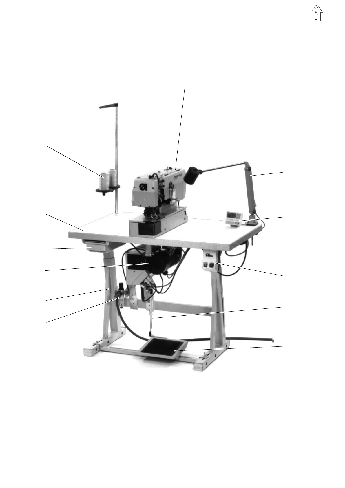
Fig. A
11
1
10
12
5
4
7
6
8
13
9
14
2
1. Scope of delivery
The scope of de l i ver y d ep en ds o n your order. Before proceedi n g t o t he
installation, check whether all the necessary parts are available.
–
Reel stand
–
Position transmitter
–
Belt guard
–
Control pa ne l
–
Table to p
–
Main switch
–
Sewing motor
–
Stand
–
Conditioning unit
–
Machine head
–
Drawer
–
Pedal rods
–
Pedal
–
Auxiliary equipment (depending on the order, e.g. sewing light 10 )
–
Tools and small parts in the accessories
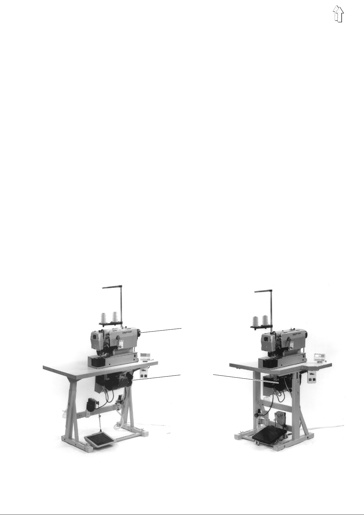
The automat ic un i t c a n b e s u pp l i ed wi t h t hree different stand t y pe s :
–
Stand set for transversal installation ( Fig. A )
–
Stand set f or l o ng i tu di n al i n s ta l lation ( Fig. B
–
Stand set for transversal/longitudinal operation ( Fig. C )
1
2
3
4
5
6
7
8
9
11
12
13
14
Fig. B Fig. C
2
3
7
3

2. General and T ransportation Safety
NOTE !
The automatic sewing unit should be installed exclusively by a
properly qualified staff.
2.1 Transportation safety
Remove the saf et y ba nd s an d t he wo od bo rde r s fr o m t he ma chi n e
head, from th e m ach i ne ta bl e –
and from the st an d.
3. Completing the stand
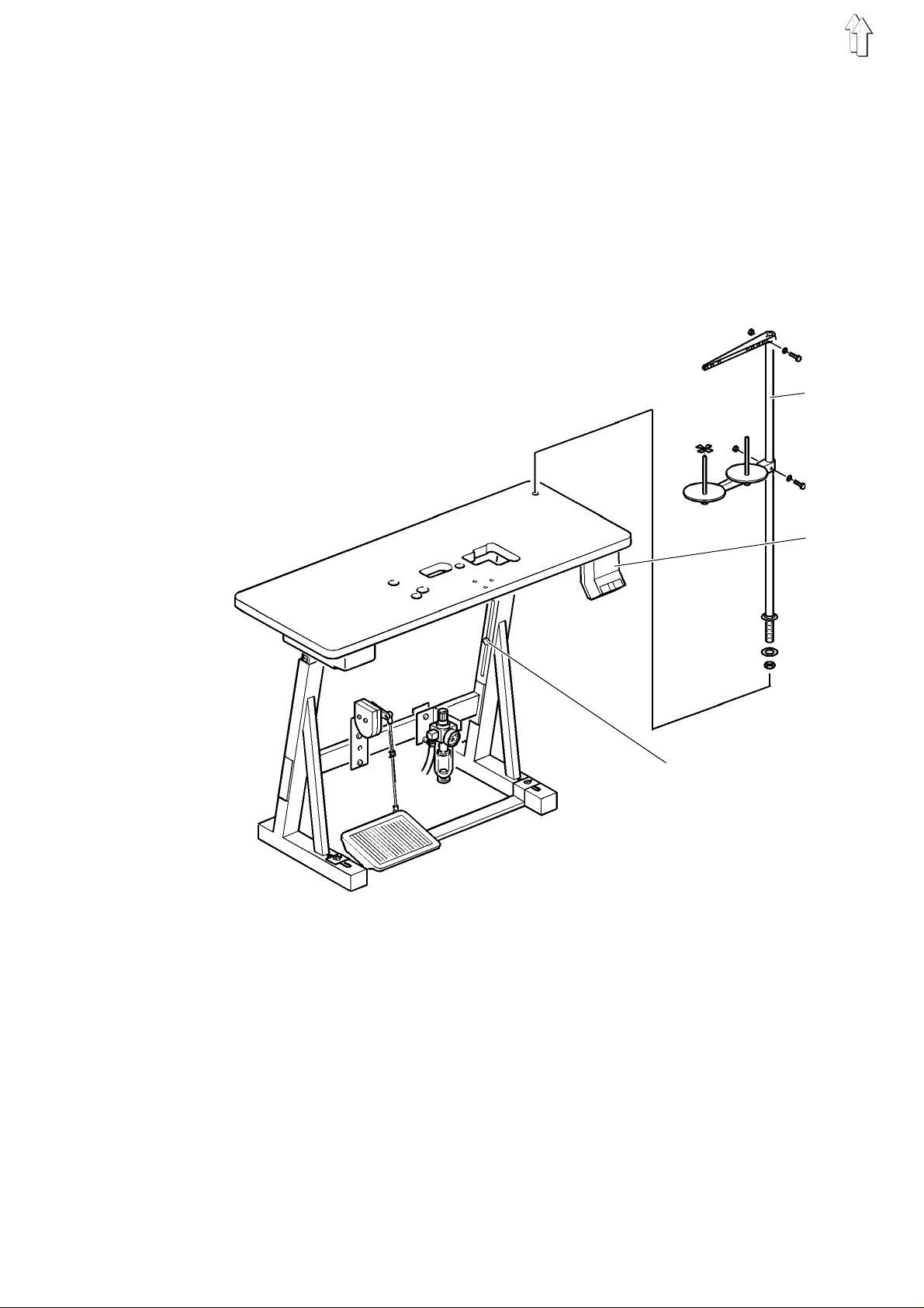
3.1 Completing the table top
–
Introduce the reel stand 1 into the bore ho l e i n th e t ab l e t op and
fasten by t he ava i l ab l e n ut s an d w as h er s .
3.2 Setting the working l evel
In case of not fully-assembled automatic sewing units:
–
Fasten the main switch 2 under the tab le top.
–
Fasten the el ec t ri c al c o nn ection cables und er t he table top.
The working lev e l can be s et be tw ee n
(Measured up to the table top ).
In order to av oi d a jamming of the stan d, push the table to p i n an d out
equally on bo th s i de s .
The scales on the sleepers can be used as adjustment aids..
–
Loosen the sc r ew s 3 on both sides of the stand.
–
Set the tabl et op s o t ha t i t i s at th e d es i re d l e v el a nd i n h ori z o nt al
position.
–
Tighten both screws 3.
750 and 895 mm
4
1
2
3
5
4. Installing and connecting the sewing motor
4.1 Genera l
Driver package
A complete driver package, depending on the order, can be supplied
for the autom at i c s ew i ng un i t c l . 57 7- 1111:
–
Sewing moto r
–
Control panel
–
Set point ge ne rator
–
Belt pulley
–
V-belt
–
Wiring dia gra m
–
Fastening an d c o nn ec t i on ma te ri al
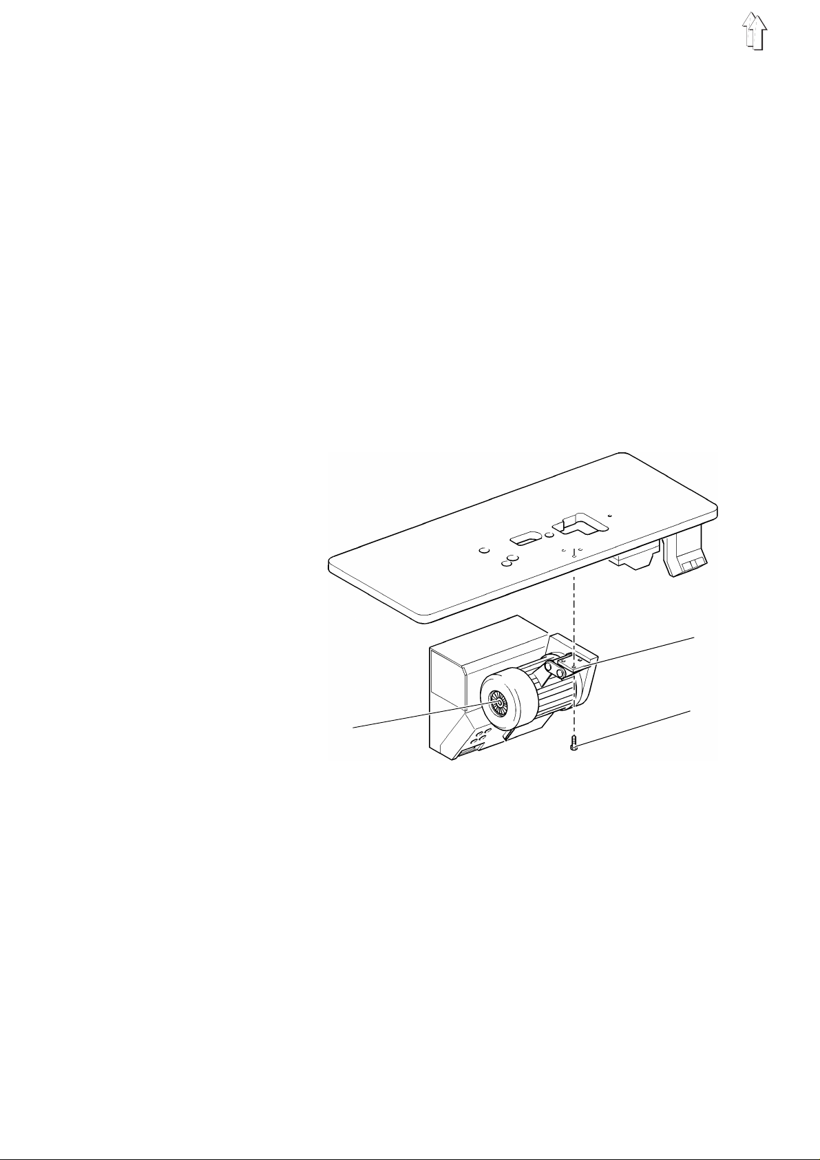
4.2 Installing the sewing motor under the table top
2
–
Fasten the bas e 1 of the sewing motor 2 by 3 screws 3 ( M8 x 35 )
on the under si de of th e table top.
1
3
6

4.3 Connecting the sewing motor
4
5
7
6
8
NOTE !
Any work on th e e l ect r i cal e qu i pm en t o f t he au to ma tic s e win g u ni t
should be ca r ri ed ou t e x c l usi v e l y by t he pr o pe r l y qu al i f i ed el e c tri c i a ns
or by the properly qualified staff!
The mains pl u g m us t be pu l l ed ou t!
It is absolutely necessary to respect the manufacturer’s instructions,
supplied toge th er w ith th e s e win g m ot or!
–
Pass the cable 4 from the cont r ol b ox 5 to the main swi t ch 6.
–
Introduce th e p l ug 7 of the motor cable into the bush 8 on the
control box.
7

4.4 Checking the nominal vol tage
NOTE !
The nominal v o l ta ge , s t at ed on th e t y pe pl a te . S h ould agree with th e
local voltage!
1
3 - 2 : 190 V
3 - 1 : 200 V
4 - 2 : 210 V
4 - 1 : 220 V
5 - 2 : 230 V
5 - 1 : 240 V
5 4 3 2 1
15
230 V
Use the termina l s 1 t o 5 on th e t ran s fo rme r 1 of the sewing unitfor adapting t o the local voltage.
At the moment of de l i v ery, the sewing motor is set to a ma ins v o l ta ge
of 230 V ( term i na l s 5 and 2 ).
–
Check the arra ngement of connect i on s on th e t r an s fo rmer of the
sewing motor.
–
If necessar y, change the co nn ections accordin g t o t he l oc a l
voltage.
The direct current sewing drives are operated by a single-phase a.c.
current.
In order to avoid an overload of a single phase when connecting
several machines to a threephase current, please note th e f oll o wi n g:
–
The connections of the single machines must be evenly distributed
onto the phas e s of th e t hr e ep ha s e li n e.
–
The wiring of the connection to the threephase line is shown in the
wiring dia gr a m.
8

5. Placing the automatic sewing unit
86
4
5
3
14
7
12
6
13
5
9
11
2
10
316
5.1 Placing the base on the table top in position
–
Fasten the square 2 to the threaded bushes of the table top.
–
Screw slig ht l y th e r u bb er- m et al c o nn ec t i on 3 from below.
–
Place the base 4 in position an d f as t en by s cr e ws 5 .
–
Tighten the rubber- m et al c o nn ection from below.
–
Screw the earthing cable
5.2 Place machine head in position and connect
–
The machine he ad s ho ul d be removed from the sh i pp ing box by
two persons, wh o s h ou l d s e i ze i t at the shaft end an d u nd er t he
base plate, bu t n ot i n t he ar e a o f t he ne ed l e t hr e ad c ut te r.
–
Hang the machine head into the base 4 and turn-in the screws 6.
–
Clamp the l i nk 7 under the scre w 6 and under the pin 8.
–
Hang-in first the spring 9 and then the s p ri ng 10
–
Introduce th e s u pp l y c ab le 11 of the control and fasten by a screw.
–
Connect the pneumatic hose 12.
–
Screw the earthing cable
foot 15.
14
to the base 4 and to the moto r 15.
13
to the head and then to the motor
5.3 Adjusting the damping
–
Turn the screw 16 so that the bo tt om of th e base plate is pa ral l e l to
the top of the b ase wh en th e m ac h ine i s in i t s lowered position.
9

5.4 Adjusting and connecting the pedal
1
6
5
8
7
3
2
4
Stand set for longitudinal installation and stand set for
transversal i nst a ll at i o n
–
Adjust the pe dal 1 on the stand strut 2 sideways so that the middle
of the pedal stands more or less under the middle of the needle.
–
Screw the pedal 1 to the stand strut.
Stand set for transversal/longitudinal operation
When using this stand set, the pedal can be adapted to the different
working positions as follows:
–
Lift the bal l ha nd l e 3.
–
Turn the pedal platform 4 according to the working position and let
the ball ha nd le 3 engage in the en d p os i t i on .
For all stand sets
–
Screw set po i nt ge ne r at or 5 to the stand.
–
Introduce the plug of the set point generator 5 into the bush 6 of
the control box.
–
Suspend the pe da l rod s 7 in the set poin t g enera to r 5.
–
Loosen slig ht l y th e cl a mp i ng s c rew 8.
–
Adjust the pedal rods so that the released pedal 1 has an
inclination of
–
Tighten the clampin g s c rew.
about. 10°
.
10

5.5 Installing and connecting the control panel
10
11
9
13
12
–
Remove the designation strip 9 of the cl. 57 7 f rom th e driver
package and introduce it into the control panel.
–
By using the available fastening material, fasten first the control
panel 10 to the square 11.
–
Then install the square 11, together wi th th e co nt rol p an el 10, on
the table top .
–
Lead the connecting cable of the control panel to the control box,
by passing it through the hole in the table top.
–
Introduce th e p l ug of the control pan el into the bush
by a screw.
The illustration shows the rotary connection of the control panel when
using a stand for tran sversal/longitudinal operation.
Turning the control panel
–
Loosen the clamping lever 13.
–
Turn the control panel in the desired position.
–
Tighten clamping lever 13.
12
and fasten
11

5.6 Placing and tensioning the V-belt
2
5
3
1
–
Remove the hand wh ee l an d t he ho usi n g c o ver f rom th e m ac h i ne
head.
–
Remove the skip guard 1.
–
Place the V-belt 2 onto its pulley 3 and pass it down through the
cutout in the ta bl e to p.
–
Install agai n th e s k ip guard 1.
–
Remove the V-belt covering from the sewing drive.
–
Loosen the mo to r fa s te ni n g n uts 4 and place the V-belt 2 onto its
pulley 5 on the sewing drive.
–
By swingin g t he en ti r e sewing motor, adjust the ten s i on of th e
V-belt so that it can be lowered in its middle
exerting a s li g ht pressure.
–
Tighten the nuts 4.
–
Fit the V-belt covering on the sewing motor as well as the housing
cover and the handwheel on the machine head.
4
about 10 mm
when
12

6. Fitting, connecting and adjusting the position transmitter
6.1 Fitting the position transmitter
7
6
–
Slip the position transmitter 6 onto the shaft.
–
Tighten the screws 7.
–
Set the pos iti o ns ( se e c h ap te r 6. 3 ) .
6.2 Connecting the position transmitter
8
7
–
Pass the co nn ec t i ng cable of the positi o n t r an s mitter through the
hole in the t ab le top and introduc e t he pl u g i n to th e b us h 8 in the
control box.
13

6.3 Checking ands adjusting the positions
There is no nee d to make any mecha ni cal adjustments on th e p os i t i on
transmitter. It is only necessary to check the stop position and, if
required, to set the reference position before the first use of the
machine..
Position
0
1
2
Stop position
Check stop position
–
Connect main switch.
The machine runs into stop position or it is already in the stop
position, i . e. :
The thread ta k e-u p l e v er stands in the top de ad c en tr e .
•
The needle do es n ot pr o j ect under the sewin g b as ke t.
•
Position of the automatic sewing unit
Reference position
Thread take-up lever short before its top dead
centre,
Rig pin 1 in the groove of th e a r m s h af t
Needle bott om po s i ti o n
( bottom dead centre )
Thread take-up lever short before the top dead
centre,
Rig pin 1 in the groove of th e a r m s h af t
Position 0
( =
Thread take-up lever in its top dead centre,
The needle do es n ot pr o j ect under the sewin g
basket. ( short after
)
Position 2
)
0 position
•
1
–
Setting the reference position
Call up correction mode
–
–
–
Change over to th e t ech i c ian l eve l
–
–
Enter reference position
–
handwheel agai n s t t he arro w d i r ect i on . Th e r i g pin 1 will then
snap into the groove of the arm shaft..
Complete a full sewing sequence.
If the stop position is not reached, the display of the control panel
will present the error message
Then it will be necessary to set the reference position as follows:
Disconnect main switch.
Hold the key
main switch.
Release the key
Enter Code-Number
( See Operati n g Instructions of th e manufacturer. )
Press the key
The control will change over to the technician,
the parameter
Select para me te r nu mb er
can be reached by a slight rotation of the
"_0 0 1 0"
"P"
on the contro l pa ne l pr e s sed do wn and connect
"P"
.
"1907"
"E"
.
"F - 100"
.
will be displayed.
"F - 170"
.
.
14
–
Press the key
The display will show
"E"
.
"Sr 1"
.

–
Press the key
The display will show
–
Turn the handwheel in t he di re c ti o n o f ro ta ti o n ( s e e t he arr o w o n
the belt guad ) un ti l t he di s p l ay e d sy m bo l di s a pp ea rs an d h e
position
–
Press the key
The reference positin will be accepted and the display will show
the parameter
–
Repeat the setting process ( Parameter
the referenc e p osi t i on ha s no t b ee n memorisd and the di sp l ay
shows the error message
Quit the correction mode
–
Press the key
The sewing basket will be lifted.
Memorise the setting
–
Lower the pedal forwards and release a complete sewing cycle.
The control will memorise he new setting.
Control the setting
–
When turnin g b ac k vi a th e
necessary to lower the sewing basket ( see the Service
Instructions ).
Ta ste B
Position 0
"E"
- 171"
"P" two times
.
"Pos 0
( reference position ) is reached.
.
.
together with a circular symbol.
"F - 170"
"in A3"
Position 0
.
.
(reference position ), it is
), if
NOTE !
The setting will be lost if no complete sewing cycle has been
performed before switching off the main switch!
15

7. Pneumatic connections
NOTE !
A perfect function of the pneumatic elements will only be ensured if the
line pressur e ranges between 8 and
The service pressure of the automatic sewing unit amounts to
The pneumatic system of the automatic sewing unit and he auxiliary
equipment mu s t b e supplied with water-free and oil -fr e e c o mp r ess e d
air.
10 bar
.
6 bar
.
2
5
4
3
7.1 Connecting the conditioning unit
–
Install the conditioning unit possibly on the stand.
–
Connect the hos e 2 of the machine head.
–
Connect the conditioning unit by a connection hose ( Ø = 9 mm )
to the compressed air line.
Pneumatic connection package
Under the
pneumatic co nn ec t i on pa c k ag e f or the stand with co nd i ti o ni n g u ni t an d
for the auxiliary equipment:
–
Connection hose, 5 m long, Ø = 9 m m
–
Hose nozzles and hose binders
–
Coupling socket and coupling cover R 1/4"
reference number. 0797 003031
3
it is poss ibl e to ob tain a
7.2 Adjusting the service pressure
–
The service pressure is shown by the manometer
amount to
–
For adjusting the service pressure, lift and rotary handle 5 and turn
it accordingly.
Turn clockwise = for increasing the air pressure.
Turn counter clockwise = for reducing the air pressure
16
6 bar
4.
It must
.

8. Lubrication
CAUTION: DANGER OF ACCIDE NTS !
Oil can irritate the skin.
Avoid long co nt ac t s with the skin!
Following a c o nt ac t , w as h th e s k i n th oro ug hl y !
NOTE !
The handling and the disposal of mineral oils is subject to legal
regulations.
Deliver wa s te oi l exclusively to an authorized rec ep ti o n c e nt er !
Protect your environment, do not spill any oil!
For filling the oil supply containe rs, used exclusively the lubrication oil
ESSO SP-NK 10
–
Viscosity at 40 °C: 10 mm
–
Point of inflammation: 150°C
or an equivalent oil with the following specification:
2
/s
The oil can be ob ta i ne d f r om th e sales centres of
DÜRKOPP ADLER AG under the following referenc e numbers:
–
2-Litre container: 9047 000013
–
5-Litre container: 9047 000014
8.1 Filling the oil supply container
Lubricate the hook
1
–
Lift the machine head.
–
Fill the supply container 1 through the filling hole up to the mark
"max"
–
Lower the machine head.
.
17

Lubricate the machine head
2
–
Fill the supply container 2 through the filling hole up to the mark
"max"
.
8.2 Lubricate the wicks and the felt parts
Before the fi r s t u se o f t he ma c hine and after its l o ng s to ps i t i s
adviseable to slightly lubricate the wicks and the felt parts.
8.3 Regulating the hook lubrication
NOTE !
For ensuring a s u ffici e nt l ub r i cation during the ru n- i n pe r iod , a rather
high oil supply quantity has been set by the factory.
Check the setti n g a nd c orre c t i t af te r th e r u n-i n pe r iod , i f ne c ess a ry
( see the Service Instructions ).
18
3
–
The oil supp ly qu an ti t y c an be r eg ulated by the screw 3
( see the Service Instructions ).

9. Sewing test
Following the installation work, carry out a sewing test as follows:
–
Insert the mains plug.
CAUTION: DANGER OF ACCIDE NTS !
Switch off the main switch!
Switch off th e m ac h ine before threadi ng th e h oo k !
–
Thread the hook for winding ( see the Service Instructions ).
–
Switch on the main switch.
–
Wind the bobb i n a t lo w s p ee d.
CAUTION: DANGER OF ACCIDE NTS !
Switch off the main switch!
Switch off th e m ac h ine before threadi ng th e n ee dl e an d t he ho ok !
–
Threading the needle and the hook ( see the Service Instructions ).
–
Insert the material to be sewn.
–
Start the se win g t es t at l ow s peed an d i n c rea s e t he spe ed
continuousl y.
"+"
( keys
–
Check whet he r th e b uttonhole meets the expectations .
"-"
/
on the control p an el o f t he machine )
If the expected results are not met:
–
Alter the thread tension ( see the Service Instructions ).
–
If required, check and correct the settings specified in the Service
Instructions.
19
 Loading...