


Contents: Page:
Home
Part 2: Installation Cl. 195
1. General Information
1.1 Safety Notes . . . . . . . . . . . . . . . . . . . . . . . . . . . . . 3
1.2 Machine Operation without Material . . . . . . . . . . . . . . . . 3
1.3 Table Tops . . . . . . . . . . . . . . . . . . . . . . . . . . . . . . 3
2. Frame Assembly . . . . . . . . . . . . . . . . . . . . . . . . . . 6
3. Table Top, Completing and Screwing on . . . . . . . . . . . . 7
4. Connecting the Sewing Drive to the Table Top . . . . . . . . . 8
4.1 General . . . . . . . . . . . . . . . . . . . . . . . . . . . . . . . . 8
4.2 Drive Mounting . . . . . . . . . . . . . . . . . . . . . . . . . . . . 8
4.3 Voltage Compensation Motor/ Machine Head . . . . . . . . . . . 8
4.4 Attaching the Rod and Pedal . . . . . . . . . . . . . . . . . . . . 9
4.5 Electrical connection of motors . . . . . . . . . . . . . . . . . . . 9
5. Positioning the Machine Head, V-belt Placement,
Attaching the B el t Gua r d an d Ha ndw h ee l . . . . . . . . . . . . 10
6. Making the Plug Connections to the Motor Control
and Attaching the Syn ch ron iz er . . . . . . . . . . . . . . . . . 11
7. Connecting the Compressed Air Maintenance Unit . . . . . . 12
8. Readying the Machine for Operation . . . . . . . . . . . . . . 12
8.1 F itting oil recycling device . . . . . . . . . . . . . . . . . . . . . . 13
9. Setting th e S yn ch r onizer . . . . . . . . . . . . . . . . . . . . . 14


1. General Information
1.1 Safety Notes
Special Attention!
The mains voltage and the nominal voltage listed
on the motor identification plate must be the same.
All work on the electronics is to be conducted only
by authorized pe rs on ne l and w it h the mai ns plu g
disconnected.
Please observ e th e sa fe ty i ns tructions!
Installation is to be co nd uc ted according to the
following instructions . All necessary parts are to be
found in the enclosed package.
1.2 Machine Operation without Material
Attention!
First arrest the pressure foot in the open position
and set the shortest pre ss ur e foot str ok e.
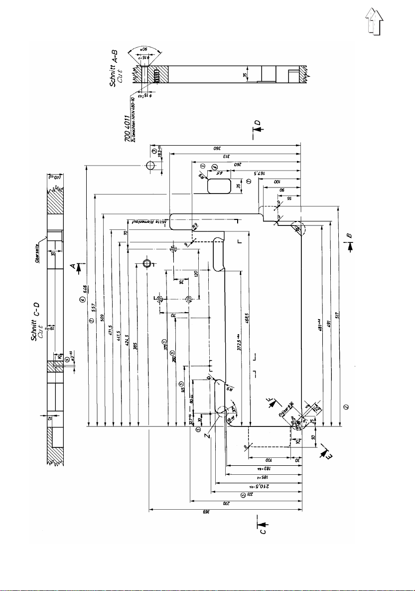
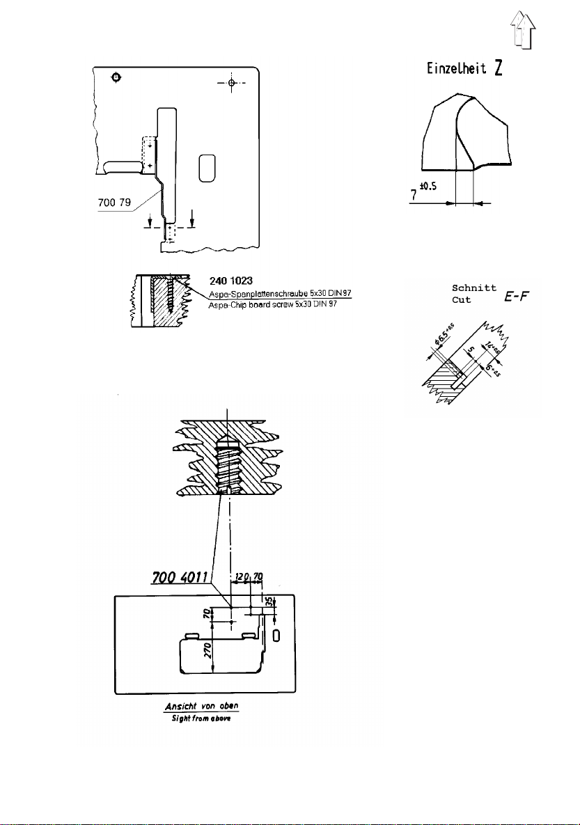
1.3 Tab le Tops
The cutouts in self-made table tops must have the
dimensions shown in the sketches on pages 4 and 5.
The table tops must have the necessary load
capacity and firmness.
345

2. Frame Assembly
2
–
Mount the frame parts
as illustrated.
–
Align the frame with screw 1 so that
all of the feet rest equally.
–
Loosen scre ws 2 an d se t th e ta bl e to p
to the correct work height.
1
6

3. T able Top, Compl eting and Screwing on
8
Underside of the Table Top
–
Fasten the reinfor ce men t brac e 5 w it h 4
screws between the cutouts of the sewing
head and the belt guard .
–
Mount the oil baffle 4 with wood screws. Alig n
the oil baffle so that the distance from the right
side of the oil baffle to the table top cutout is
55 mm.
–
Screw on the reinforcement brace 7 behind the
oil baffle.
–
Screw on the cable duct 3 and the holder 6 for
the connection cable strain reliever.
–
Screw on the main switch 2.
–
Screw on the sewing light transformer 1 (if
supplied).
–
Screw on the drawer 8 with its mounting.
Secure the ins ert pl at e ag ai ns t di spla ce men t
with a nail.
–
Screw the tabl e top on to the fra me w it h B8X 3 5
wood screws.
The position of the table top relative to the
frame is determin ed by the ce nt er ing mar ks on
the underside of the table top.
1
2
3
4
5
6
7
Top of the Table
–
Press the rubber rests for the hinges and the
forward rest points into the table top recesses.
–
Press the plug into the intended hole.
7

4. Connecting the Sewing Drive to the T able Top.
4.1 General
Different drive an d conn ec ti on s pa ck ag es are
available for the machine. The drive package
consists of:
Motor, motor protection switch with wiring, belt,
belt pulley.
The connections package contains all wiring
between the motor and the sewing head.
The direct curren t dr iv e av ai la ble fo r th is mach in e
is operated by a "mo no phas e al te rn at in g vo ltag e" .
Therefore, with multiple machines, the connections
must be uniformly dis trib uted to th e indi vi du al
phases of the main s su pply (3 phase). Otherw is e
this could lead to an overload of the individual
phases.
Attention!
If the electronics are not suppli ed by Dür ko pp
Adler, then manufacture and testing is to be
conducted to
EN 60204-3-1/JE C 20 4- 3-1.
4.2 Drive Mounting
–
Screw the drive with its base to the table top.
Hereby screw 3 M8 x 35 hex head s crews with
washers into th e nu ts in th e ta bl e to p.
–
Fasten the V-belt pulley to th e mot or sha ft .
–
Check the arrang eme nt of the co nn ec ti on s on
the motor terminal board and correct if
necessary.
The arrangement must be appropriate to the
mains voltage.
4.3 Volt age Comp ensation Moto r/ Machine Head
–
Screw the conne ct in g ca bl e fo und in the
enclosed package onto the motor base. It
serves to conduc t th e st at ic cha rge of the
machine head to ground via the motor.
8

4.4 Attaching the Pedal and Rod
For ergonomic reasons the lateral direction of the
pedal is to be aligned centered to the needle. Set
the rod so that the peda l ha s an inc li ne of 10 °.
4.5 Electrical connection of motors
The required technical connecting data are listed
in the circuit diagram en closed in the drive
package.
9

5. Positioning the Machi ne Head, V-belt Placement,
Attaching the Belt Guard and Handwheel
2
–
Set the sewin g he ad i nto the ta bl e to p cu to ut .
–
Fold over the se wi ng hea d an d re mov e th e
safety bar 1.
–
Plug the arresting pin 2 into one of the notches
of the built-in adju st men t disc.
–
Screw off the handwheel.
–
First place the V-belt over the machine belt
pulley.
–
1
Place the belt on the mot or bel t pull ey.
By swinging the motor tension the V-belt so
that it can be pressed in at its center by about
10 mm without great effort.
–
Screw on the belt guard with 5 screws.
When folding over, the belt guard must go into
the table top cuto ut uni mpa ir ed .
–
Screw on the mot or be l t guar d.
Set the securing cams so that the belt does
not slip out of the be lt pul le y w he n the se w in g
head is folded over.
–
Screw on the ha nd whe el .
The correct posi ti on of th e ha nd whe el i s
derived from the ad diti on al hol es in th e ha nd
wheel and on the belt flange. They must lie
congruent.
10

6. Making the Plug Connections to the Motor Control,
Attaching the Synchronizer (Only Positioning Drive)
2
1
–
Fold over the machine
–
Connect the voltage compensation lead 1 to
the head.
–
If supplied, connect the external control panel.
–
Lay the wiring for buttons, control panel and, if
supplied, sewing light in the head cable duct.
Attention!
Before installing the synchronizer, switch off
the thread trimmer function on the control
panel.
–
With the machine switched off, push the
synchronizer onto the handwheel so that its
groove catches over the mounting pin on the
belt guard.
–
Arrest the handwhe el in po si ti on A.
–
Screw on the synchronizer.
Position the marking 2 directly opposite the
notch 3.
This is position "0", the dependent initial
position for all machine position settings made
at the factory.
For setting the 1st and 2nd needle positions
see Section 9.
3
11

7. Connecting the Compressed Air Maintenance Unit
5
1
2
For operation of the pressure foot stroke, stitch
condensation and thread trimming, a supply of
water-free, li gh tl y oi le d co mpr es se d ai r is req ui re d.
–
Screw the maintenance unit to the frame.
–
Establish th e P U3- hose c onne ct io n 1 be twe en
the maintenance unit and the machine head.
–
With the compress ed ai r
off, fill lubricating oil ESSO SP-NK 10.
Open screw 2 and fill up to the grooved
marking.
–
Connect the mai nten an ce uni t co nn ec to r hose
to the compressed air supply.
–
Pull up th e handle 5 and set an operating
pressure of 6 bar by turning.
disconnected
or shut
8. Readying the Machine for Operation
–
Mounting the Yarn Stand
–
Fill the oil tank for the central oil wick
lubrication up to th e up pe r mark i ng lin e (s ee
Operating Instructions Section 2.1)
–
Plug in the mains plu g.
–
Briefly switc h on the moto r pr ot ec ti on swit ch
for three phase mot or s.
Check the direction of rotation on the motor
ventilation whe el . See arr ow on the bel t guar d.
If the direction of rotation is incorrect
interchange 2 ph as es in th e mai ns plu g.
–
Check the feed quantity of the oil mister
(approx. 1 drop every 10 work cycles). Correct
if necessary. See Section in the Operating
Instructions.
12
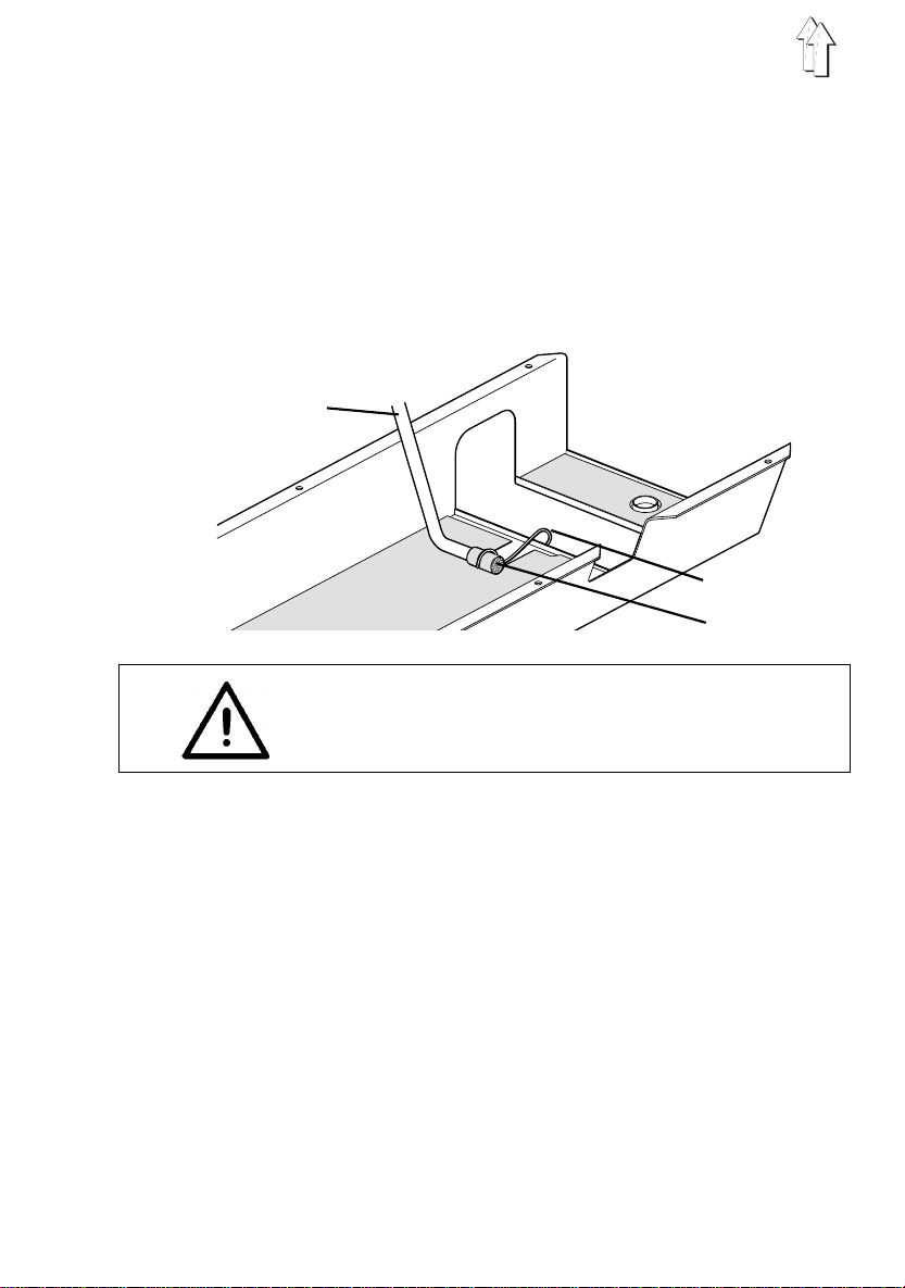
5.1 Fitting oil recycling device
The oil recyclin g de vi ce col le ct s th e oi l in the oil
sump and returns it by ap ump to th e oi l ci rc ui t.
–
Wrap intake filter 3 of th e oi l re cy cl in g devi ce
by the felt and fas te n it to th e oi l sh ee t by the
clamp 2.
–
Install the oil hose 1 and secure it so that it
cannot get into contact with mobile parts.
1
ATTENTION !
Change the oil ev ery 2 ye ar s, irr es pe ct iv e of the
number of operating hours.
2
3
9. Setting the Synchronizer
The machine positions are seen by the
synchronizer in st eps (i nc re men ts ) of 0.7° and
shown in the display. A complete revolution
corresponds to 512 steps.
1st Position
The machine should stop when the hook has
securely taken up the loop.
This means that the needle should raise above its
lower dead center until the hook tip has moved
approx. 6 mm above the needle to the left. This
corresponds to the increment number 50 .
2nd Position
Needle bar a litt le bit bef ore the up pe r de ad ce nte r.
This corresponds to the increment number 190.
13

Programming the Positions:
1. Hold key P pressed.
2. Switch on the main switch. Code-No. C 0000 appears in the display.
3. For entry to the " Technician Level 1"
enter Efka Code-No. 1907 with the keys 1 ...0.
4. Press key E. Parameter- No. F100 appears in the display.
5. Enter parameter-no. F170 with the keys 1 ...0.
Press key E. Service-Routine 1 (Sr1) appears.
Press key F. Position 0 appears.
6. Turn the handwheel one full revolution in the machine direction and
arrest in position A with the enclosed arresting pin.
Press key P twice.
7. Press key P drücken. F170 appears in the display.
8. Press key E twice. Service-Routine 2 (Sr2) and F171
9. Press key F. Position 1 and the set increment number
Using keys + or - set the increment number 50.
10. Press key E. Position 2 and the set increment number
Using keys + or - set the increment number 190.
11. Press key E. Position 1A and the set increment
Using keys + or - set the increment number 100.
12. Press key E. Position 2A and the set increment
Using keys + or - set the increment number 240.
13. Press key P twice. This completes the setting.
14. Attention!
It is essential that a seam be sewn with thread trimming and raising the
pressure foot. This is the only way for a setting to be definately stored in
the memory. Without sewing the setting is lost when the machine is next
turned off.
appear in the display.
appear in the display.
appear in the display.
number appear in the display.
number appear in the display.
14
 Loading...