


Contents: Page:
Home
Preface and General Safety Information
Descriptio n of pr oper us e or pro pe r app lic ati on
Part 1: Operating Instructions Cl. 195
1. Product Desc ription . . . . . . . . . . . . . . . . . . . . . . . . 5
1.1 Short Description and Proper Use . . . . . . . . . . . . . . . . . 5
1.2 Sub-Classes . . . . . . . . . . . . . . . . . . . . . . . . . . . . . 5
1.3 Technical Speci ficat ion . . . . . . . . . . . . . . . . . . . . . . . 6
1.4 Optional Equipment . . . . . . . . . . . . . . . . . . . . . . . . . 6
2. Operating Elements and Their Function . . . . . . . . . . . . 7
2.1 Elements at the Sewing Head . . . . . . . . . . . . . . . . . . . . 7
2.2 Elements on the Frame . . . . . . . . . . . . . . . . . . . . . . . 11
3. Operating the Sewin g Machi ne . . . . . . . . . . . . . . . . . . 13
3.1 Threading the Needle Thread . . . . . . . . . . . . . . . . . . . . 13
3.2 Needle Thread Quantity for Sure Stitch Formation . . . . . . . . 14
3.3 Threading the Bobbin Thread . . . . . . . . . . . . . . . . . . . . 15
3.4 Setting the Thread Tensions . . . . . . . . . . . . . . . . . . . . . 16
3.5 Setting the Bobbin Thread Take-Up . . . . . . . . . . . . . . . . . 17
3.6 Setting the Pressure Foot Stroke . . . . . . . . . . . . . . . . . . 18
3.7 Edge tr immer shut-on and shut-off . . . . . . . . . . . . . . . . . 19
4. Maintenanc e . . . . . . . . . . . . . . . . . . . . . . . . . . . . . 20

Following Patents and R eg ist er e d Ut ilit y Mod el s ap ply:
Status April 1994
DE 30 43 141 JP 1 258 920
IT 209 238 JP 1 339 944
KR 24 686 JP 1 803 181
TW 31 498 JP 1 931 464
US 4 116 145
US 4 446 803

1. Product Description
1.1 Short Description and Proper Use
The special sewing machine 195 is a single needle-double chain stitch
machine with lower transport and an upper transport with alternating
pressure feet. The hook of the 195 is set crosswise to the direction of sewing
(Crossline). With the part s set 195 5002 it can be converted to a two-n eedle
sewing machine.
The machines are designed and may only b e used for sewing materials of
textile fiber and leathe r.
As of 11/95 Class 195-171110 is equipped at the factory so that thread
thicknesses great er th an 25/3 N m ca n be sewn (ai r bag pr o du ct ion) .
For this, the machine and the pa rts kit 195 50 02 eac h have a second hoo k,
this means that:
The single needle machi ne can be equipped with
hook 195 4753 for threads up to 25/3 Nm or with
hook 195 4753a for threads thicker than 25/3 Nm as required.
The dual n e edle machine can be equipped with the
hooks 195 4753 and 195 5055 for threads up to 25/3 Nm or with
hooks 195 4753a an d 19 5 50 55 a for threa ds thicker than 25/ 3 Nm as requ ir e d.
Attention!
The hook or hooks not inserted in the machine are enclosed with the machine.
1.2 Sub-Classes
195-171110 Execution without thread trimmer.
195-171521 Execution with electropneumatic
Electropn eu ma ti c li ft in g of the
pressure foot
thread trimmer for needle and
bobbin thread, electropneumatic
automatic interlock and
pressure foot stroke
5

1.3 Tec hnical Specification
Needle system: 933
Maximum number of stit ches : 4000 rpm
Maximum stitch len gt h: Upper transport 10 mm
Maximaler pressure foot stroke: 2-7 mm
Clearance under the pressure feet:
when sewing: 10 mm
when raised: 17 mm
Maximum thread thickness: 20/3 Nm
Operating press ur e : 6 +/- 0,5 bar
Line pressure: 7-10 bar
Air consumption per work cycle:
-171110 0,05 Nl
-171521 0,1 Nl
Through-feed area : 280 x 132 mm
dependent on pressure foot stroke
and stitch length
Lower transport 8 mm
1.4 Optional Equipment
195 5002 Parts set for converting a single-needle
Z 133 601 Reflecting light barrier for recognizing
Z 132 1501 Needle cooling from above.
to a two-needle machine. Max. needle
pitch 14 mm dependent on the E-Nr.
Not
for 195-171521.
the seam end.
6
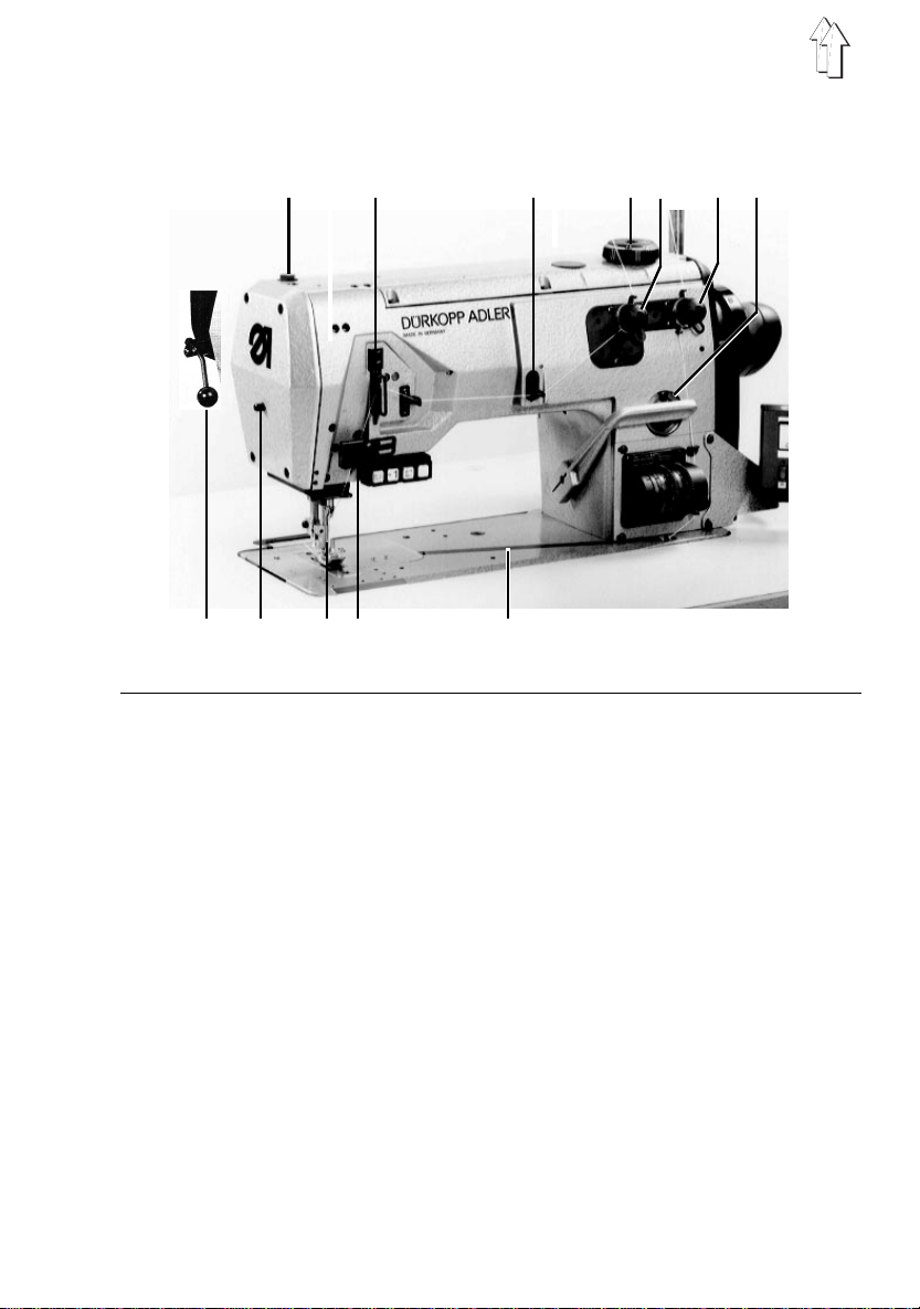
2. Operating Elements and Their Function
2.1 Elements on the Sewing Head
1
234567
12
Element Function
1 - Screw - This screw for the pressure foot pressure is
2 - Thread regulator - Setting the correct needle thread quantity
3 - Needle thread puller - For formation clean stitches at the beginning of
4 - Adjustment wheel - Setting pressure foot stroke.
5 - Contr ol knob - Setting needle thread tension.
6 - Control knob - Setting bobbin thr ea d te ns io n.
7 - Viewing glass - Show the oil level in the reservoir. The oil level
with fill opening must be kept above "MIN". If necessary fill
8 - Plate - Bobbin thread guide
9 - Light barri er - Recognition of the mater i al edg e an d ther e by the
10 - Needle - 933, Needle thicknesses depending on the sewing
11 - Knob - Lock the pressure foot in the raised position.
12 - Lever - Ed ge tr im me r shu t-o n an d sh ut- of f. (195-671110)
91011
screwed in completely at the factory.
Do not alter the scr ew posi ti on !
the seam pull out su ff ic ie nt thr e ad .
"Esso SP NK 10" oil up the the "MA X" marking.
precise position of the stitch condensation at
the seam end.
garrangement. Caution Risk of Injury!
8
7
Element Function
13
bac1415161718
13 - Operating field - See motor manufacture r ’s instruct io ns
14 - Bobbin thread- - For formation a clean stitch at the seam beginning
puller pull out suffic ie nt thr e ad .
15 - Adjustment wheel - Setting the stitch length of the upper t ransport.
16 - Adjustment wheel - Setting the stitch length of the lower transport.
17 - Screw - Setting the stitch condensation
18 - Hand lever - Continuous adjustm ent of the stitch length.
8
Note: For thread tri m m in g wit h th e su b- c la ss
171521 the thread wiper on the threa d
trimming key must also always be turned on.
Diodes a and b must be lit.
The upper diode c must be lit on the "S titch
Condensation at the Seam End" key.
(Length of the stitches).

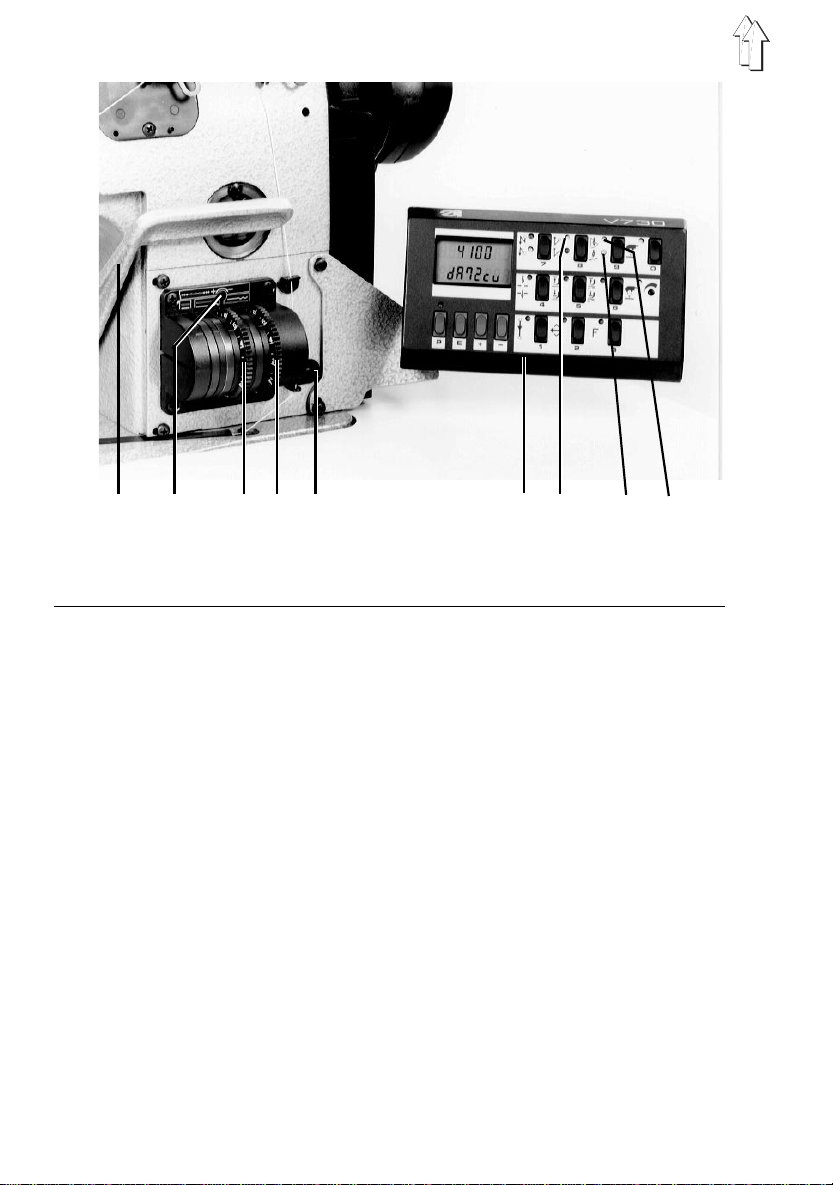
1617181920
Element Function
16 - Block of Keys
17 - Key - Ke y not j ust.
18 - Key - Suppression of stitch condensation at seam
19 - Key - Sew single stitches
20 - Key - Bring the needle alternatingly in position
beginning
high/low, stitch condensation at any de si r ed
seam position during sewing.
9

Element Function
20 - Dip stick - Measuring the oil level in the hook drive
21 - Screw To che ck the oi l level screw out sc rew 21
22 - Thread take-up - Automa ti c ad ap ti on of th e bo bbi n thr ea d qu an ti ty
housing . Dip stick is in the enclosed packag e.
and place the dip stick 20 in the opening. The
oil level must be between the mar ki ng s.
Fill only Esso SP NK 10-type oil.
Attention!
When overfilling the excess oi l w il l co me
out of the ventilation hole in screw 21.
to the set stitch length. Settings for tight,
normal and highly elastic seams see
Section 3.5.
UMB 2.2
20
22
10
21

2.2 Elements on the Frame
4
3
2
1
Element Function
1 - Main switch - Switch the machine on and off.
2 - Screw - Compensation for floor irregularities
3 - Pedal
Rest position - No function
Position forward - Sewing with desired rpm
Position "half back" - Raise pressure foot when machine at rest
Position "full back" - Thread trimming and raise pressure foot
4 - Screws - Adju stin g th e work height
11

Maintenanc e Uni t
11 10 9 8 7 6 5
Element Function
7 - Oil mister - With the regulating screw 5 set approx. 1 drop
8 - Air filter and - Before the water level reaches the filter, screw
water trap in screw 9 far enough to drain water.
10 - Pressure Regu la to r - To set to 6 bar pull the bushi ng 11 up
for 10 work cycles. To fill interrupt the
compressed air feed and vent the system with
screw 9. Screw out screw 6 and fill
"Esso SP NK 10"-type oil up to the groove in
the glass.
Do
not
interrupt th e co mp ressed air suppl y.
and turn ap pro priately.
UMBRUCH =
12

3. Operating the Sewing Machine
3.1 Threading the Needle Thread
1
Caution Risk of Injury!
Turn off main switch before threading.
- Thread the needle thread as shown in the
illustrations.
Important!
By machines with thread trimming it is
essential that the nee dl e th r ea d be thr e ad ed
through the pre-tensioners (1).
13

3.2 Needle Thread Quantity for Sure Stitch Formation
1
a)
b)
With elastic sewing thr e ad s, e.g. synthetic fiber
threads, a certain needle thread quantity must be
pulled out for sure stitch formation.
This occurs in the low posi ti on of th e take-u p lever
in conjunctio n wit h th e th rea d r eg ul ator 1.
For this the thread regulator is set as follows:
–
Bring the thread regulator into its lowest
position.
–
Adjust the thread regulator.
With elastic th rea ds :
The thread hole must be visible below the thread
regulator.
Thread the needle to the
With non-elast ic thr e ads, e.g. cotton:
Thread hole should be visible above the thread
regulator.
Thread the needle thread to the
Illus. b
left
past the bar. Illus. a
right
past the bar.
14

3.3 Threading the Bobbin Thread
Caution Risk of In ju r y !
Turn off the main switch be fore thre adin g.
–
Lift the thread holder 1 out of its catch.
–
Draw the thread through the holes 2 and 3.
–
Draw the thread through the hook holes.
–
Close the hook holder.
1
2
3
15

3.4 Setting the Thread T ensions
The thread tension of the needle thread must be
higher than that of the bobbin thread. The control
knob for the bobbin thr ea d te ns io n th us has a
spring of thinner wire.
Too high thread tensions cause a puckering of the
material.
Too low bobbin th read tensio ns can caus e faulty
stitches.
For setting a greater thread quantity in the seam
see Sectio n 3.5.
Furth ermore, one ca n work with or without
pneumatic tension opening during the stroke of the
sewing foot.
The tension opening is necessary when the sewing
material with thread is to be pulled forward under
the sewing foot. Here the arm cover must be
removed and the coupli ng plug in se rted into th e
preattache d coupling socket.
Attention!
When sewing corners with sewing foot stroke a
loose stitch results. Thus, pneumatic tension
opening should only be used when there is no
sewing foot stroke during the course of the seam.
16

3.5 Setting the Hook Thread T ake-up
1
2
The thread take-u p 1 pr ovi de s for an aut om at ic
adjustment of the th r ea d qu anti ty to th e se t st itch
length.
Because of this , stitch pull and stitch formation
are always optimal for every stitch length, also for
stitch condensation. The drawn-in thread quantities
can be altered for each type of seam.
Results with ou t al te r i ng the th r ea d te ns io ns ar e:
a) tight
b) normal
c) highly elastic (ballon stitch) seams.
–
Loosen screws 2.
–
Adjust the thr ea d ta ke-u p.
Direction 0 tighter seam
Direction 5 elastic seam.
Important!
1) With extreme settings, e.g. a smallest possible
stitch length and a hi gh es t po ss ible th r ea d quan ti ty
(elastic seam ) , car e mus t be taken th at a pos it ive
stitch of the needle int o th e th rea d de lt a is
possible. Faulty stitches can occ ur by too la rge
hook thread quantities.
2) If the stitch length is greatly increased by the
settings described under 1, it is necessary to set
back the thread guid e in the dir e ct ion 0. Otherwise
the hook thr ead may jump off of the thread take-up
disc.
a)
b)
c)
17

3.6 Setting the Pressure Foot Stroke
Attention!
The machine doe s no t have automa ti c r evolution
reduction. When sewing with a large pressure foot
stroke it is impera ti ve to manua ll y red uc e th e
number of revolutions.
Too high revolutions become obvious through
louder sewing noise.
18

3.7 Edge trimmer activating and deactiv ating
The edge trimmer off Cl. 195-671110 may be
actuated at any time. It’s upper knife is such as
formed that also a save cutting aktion is achieved
at activating while sewing.
1
Attention Danger of injuring
Don’t reach into cutting zone at activating the
trimmer. Remove finger guard only for repair
aktions. immediately replace finger guard at
damages.
For activating of the trimmer pull lever 1
downwardly, for deactivating push lever upwardly
19

4. Maintenance
Caution Risk of Injury !
Turn off the main switch before cleaning the
machine.
At the very latest maintenance work must be
conducted aft er th e num be r of oper at in g hour s
listed in the column " Interval". Shor ter
maintenance intervals may necessary when
working wit h ver y lin ty mat erial.
Procedure Interval Remarks
Head
Removal of lint 8 Particularly at following point s :
accumulations Underside of the stitch plate
Check oil level in the 40 See Subject 2.1
reservoir Element 10
Maintenance Unit
Clean insert in the air filte r 8 500 First vent the system
Transporter stays
Area around th e ho ok
Check oil level in the oil mister 6 180 Do not allow the oil level to fall
Check the oil feed in the oil
mister 180 See Subject 2.2
Check all compressed air lines
for leaks 500
20
the opening in th e su ctio n pi pe
 Loading...