

Page 1

Contents: Page:
Home
Foreword and general safety instructions
Part 1: Operation manual classe 171 • 173
1. Product specifications
1.1 Sho rt de scri ption and use for the intended purpose . . . . . . . . . . . 5
1.2 Technic al data . . . . . . . . . . . . . . . . . . . . . . . . . . . . . . . 5
1.3 Opt iona l equipment . . . . . . . . . . . . . . . . . . . . . . . . . . . . . 5
2. Machine elements and their functions
2.1 Elements at the m achine head . . . . . . . . . . . . . . . . . . . . . . 6
2.2 Elements at the stand . . . . . . . . . . . . . . . . . . . . . . . . . . . 10
3. Operating
3.1 Threading t he needle thread . . . . . . . . . . . . . . . . . . . . . . . . 12
3.2 Threading t he lo oper thread . . . . . . . . . . . . . . . . . . . . . . . . 12
3.3 Adjusti ng the th read tensions . . . . . . . . . . . . . . . . . . . . . . . 12
3.4 Amount of ne edle thread f or se cure stitch formation . . . . . . . . . . 12
3.5 Adjusti ng the lo oper thread t ake- up . . . . . . . . . . . . . . . . . . . . 14
3.6 Setting the feeding length . . . . . . . . . . . . . . . . . . . . . . . . . 15
a) B ottom feed . . . . . . . . . . . . . . . . . . . . . . . . . . . . . . . 15
b) Top pu ller feed . . . . . . . . . . . . . . . . . . . . . . . . . . . . . . 1 5
4. Maintenance
4.1 Cleaning . . . . . . . . . . . . . . . . . . . . . . . . . . . . . . . . . . . 16
4.2 Lubricating . . . . . . . . . . . . . . . . . . . . . . . . . . . . . . . . . 16
5. Information on sewing with monofilament threads . . . . . . . . . 18
Page 2

The following patents and registered designs apply:
Status October 1992
DE 86 20 593
JP Sho-62-108358
TW 40 985
Page 3
1. Product specifications
1.1 Short description and use for the intended purpose
The 171 and 173 are double chainstitch (stitch type 401) sewing machines in single or
twin needle version.
The loopers are across the line of sewing (Crossline).
Class 171 with drop oscillation feed.
Class 173 with drop oscillation feed and intermittent top puller feed.
The feeding lengths of feed dog and puller are independently a dj ustable at separate
dials. When changing over to stitch condensing, the feeding length of the puller is
automatically reduced accordingly.
In accordance with the intended purpose, the machines must only be used for sewing
materials made of textile f ibres and leath er.
1.2 T echnical data
Feeding length of the top puller feed: max. 7 mm
Standard puller width: 9 mm
Subclasses Stitch
length
171-131110 1-4 mm 6600 / 7000 27 mm
173-141110 1-4 mm 5800 / 6000 30 mm
173-141521 1-4 mm 5800 / 6000 30 mm
Maximum clearance under the sewing foot:
When lifting: 5 mm with the needle 934 SIN
When sewing: 4 mm
Operating pressure: 6+/-0.5 bar
Air consumpti on: On the -161120 0.05 NL per work cy cl e
On the -1 41521 0.1 NL per work cycle
Speed
at work/ max.
Needle
stroke
934 SIN or 933 depending on the sewing
equipment (E-Nr.)
10 mm with the needle 933
Stitch
condensati
Foot lifting Thread
on
•••
cutter
N
e
e
d
l
e
s
y
s
t
e
m
:
1.3 Optional equipment
Order numbers
1713502 Set of parts for converting a single nee dl e- into a twin ne edle double
chainstitch sewing m achine. Max. needle dista nce 1 4 mm depe ndin g on the
E-Nr. Not f or su bclass 173-141521.
933 5736 Steel puller 1 mm tooth ed, 9-mm-wide
933 5737 Steel puller 1 mm tooth ed, 15-mm-wide
933 5738a Steel puller 2 mm saw-toothed, 15-mm-wide
The steel pullers must not touch, the distance to the throat plate must be 0.5 mm.
For the adjustm ent see the servic e m anual. 16-mm-wi de asymmetric Vulcollan puller
and a hook kni f e are contained i n the accessor i es. The position of the puller wi th
respect to the seam or fabric fold may be varied depending on how it is mounted.
5
Page 4

2. Machine elements and their funct ions
2.1 Elements at the machine head
Element Function
Hand lever 1
Screw 2
Oil check tube 3
Dial 4
Needle thread puller 5
(Only subclass -141521)
Needle thread tension 6
Looper thread tension 7
Oil reservoir 8 with
inlet opening
Dial 9
Looper thread puller 10
(Only subclass -141521)
–
Swinging up the puller. It is swung out of the working
area.- Sewing wi th bottom feed only.
–
Regulating the sewing foot pressure depending on the
material.
–
Monitoring the oil circulation for the lubrication of t he
front arm shaft bearing. The oil flow must not be
interrupted while the machine is running. If necessary,
check the oil level in the reservoir 8 or top up with oil.
Only ESSO SP-NK 10 or an oil of the same quality
must be used.
–
Feeding length for the top feed puller.
–
Initial thread for the stitch formation at the seam
beginning after the threads are trimmed.
–
One revolution of the turning button with num erals
covers the entire tension range. Thus, the tension
values can be easily reproduc ed.
–
Same as 6, but w i th a weaker tension spring.
–
The oil level must not drop below "MIN". If necessary,
top up with ESSO SP-NK 10 oil to "Max".
–
Setting the stitch length for the bottom feed.
–
Initial thread for the stitch formation at the seam
beginning after the threads are trimmed.
Release lever 11 for
the thread tensions
Thread guide 12
Needle 13
Thread regu l ator 14
Locking button 15
6
–
Pulling out the threads by hand, eg when threading
–
Basic adjustm ent centre of t he elongated hole.
–
System 934 SIN or 933.- Needl e sizes Nm 80-130
depending on the sewing equipment (E-Nr.).
To exchange t he needle, al ways turn off the
main swi tch! - Danger of injury!
–
For secure sti tch formation i n the case of elastic
threads, such as eg synthe tic spun threads and
monofilament threads. For the adjustment see
section 3.4.
–
Locking the f oot in its lifted position.
Page 5
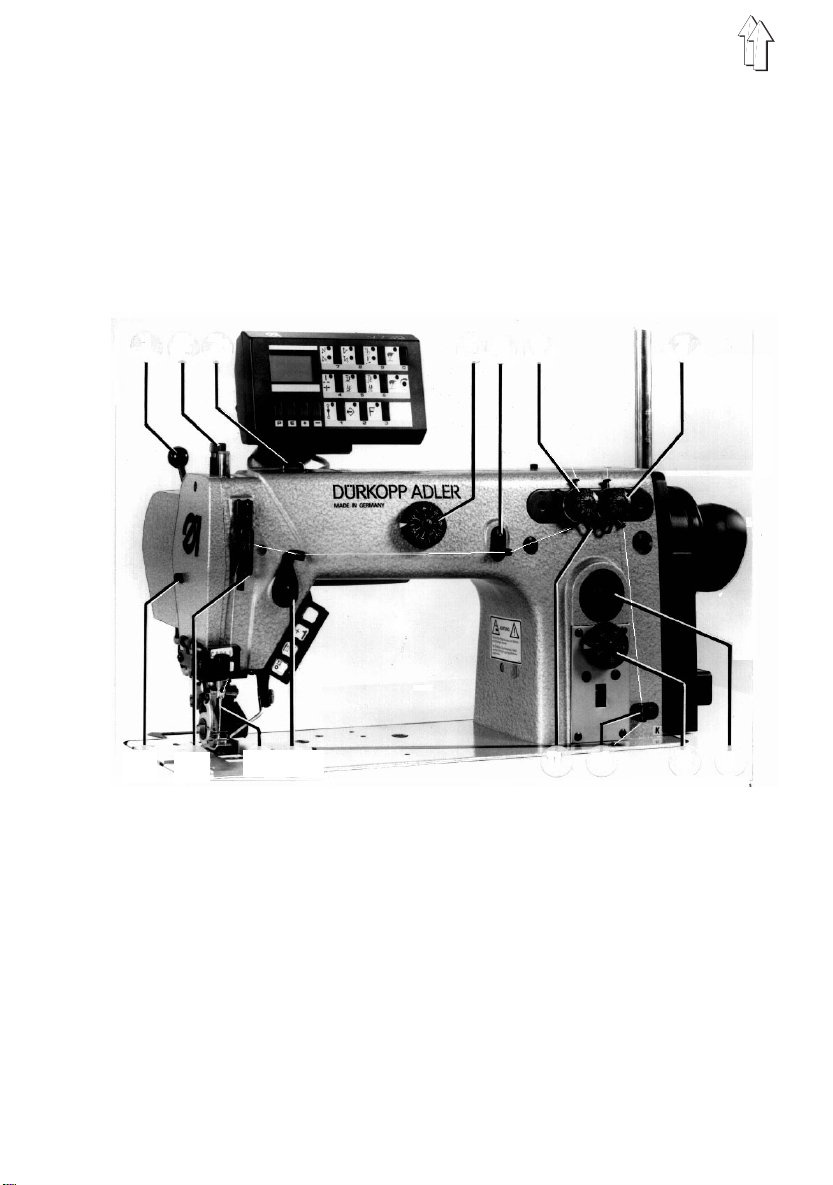
1 2 3
4 5 6
7
15 14
13 12
11 10
9 8
7
Page 6

Element Function
Key 17
Key 18
Key 19
Key 20
Control pane l 21
(Only subclasses -141521
and -161120)
Knee lever 22
Infrared reflecting
light barrier 23
Looper drive housing 24
–
Undefined
–
Single stitches
–
Needle up or down at machine standstill. During
sewing condensed stitches may be sewn anywhere within the seam.
–
Raising or lowering the puller.
–
See instructions of the motor manufacturer.
Note: To enable thread trimming on the subclass 141521, not only the key "thread trimming", bu t also
the key "thread wiping" at the control panel must be
always switched on. Diodes a and b must be luminous.
–
Prior to tilting the machine head backwards, TURN
OFF the main switch and remove the knee l ever. To unhook, make the m otions 1 and 2 an d to hook up, make
the motions 3 and 4.
–
To sense the fabric edge and thus, the correct
position of t he condensed st i tches at the sea m end.
–
With the machine head tilted backwards the oil level
must not drop below the lower long mark.
If necessary, turn out the screw 26 and top up with oil
ESSO SP-NK 10. The oil must just be filled up to the
upper mark.
Looper thread take-up 25
8
–
It automatically adjusts the amount of looper thread to
the set stitch length.
For adjustments for tight, regular or highly elastic
seams see section 3.5.
Page 7

17
18
19
20
21
a b
23
26
24
22
25
9
Page 8

2.2 Elements at the stand
Element Function
Main switch 1
Pedal 2
Maintenance unit
Air filter with water
separator 7
Pressure regulator 4
Mist lubricator 9
–
Turning on and off t he machine.
Always turn o ff the main switch prior to th reading,
changing the sewing tools ( such as eg needle,
sewing foot, thr oat plate, sl ide plate etc.),
cleaning, when leaving the workplace as well
as for ma intenan ce wo rk.
See also General Safety Instructions.
–
0 Idle position - No function.
1 Sewing foot lift at machine standstill
2 Sewing up to t he maximum speed by pressing down
the pedal accordingly.
3 Stitch condensing - thread trimming* - sewing foot
lift.
* Not on subclass -161120
–
Before the water level reaches the air filter 6, screw in
the screw 8 an d blow off the water under pressure.
–
To set the air pressure of 6 ba r, pull up the knob 4 and
turn it.
Turning to the right = Pressure increase
Turning to the left = Pressure decrease
–
Adjust approx. 1 drop of oil for 10 work cycles using
the regulating screw 11.
10
To top up with oil, vent the pneumatic system. To do
this, turn the knob 4 to the left.
Turn out the screw 10 and fill with ESSO SP-NK 10 oil
up to the gro ove on the oil re servoir 9.
Page 9

1
2
4
11
10
5
96
9
7
8
11
Page 10

3. Operating
3.1 Threading the needle
thread
Turn off main switch.
-Danger of injury! -
For threading the needle thread proceed
as shown in the figures opposite.
3.2 Threading the looper
thread
Turn off main switch.
-Danger of injury! -
For threading the looper thread also
proceed as shown in the figures
opposite. To do this, lift the thread downholder 3 out of its locked position.
3.3 Setting the thread
tensions
The needle thread tension must be
tighter than that of the looper thread.
The looper thread tension 2 is, therefore,
equipped with a spring made of thinner
wire.
Too tight thread tensions ca use compression of the ma terial. A to o l oo se
thread ten si on may lead to ski pped
stitches.
For a larger amount of looper thread
pulled into the seam see sec tion 3.5.
3.4 Needle thread amount for
secure stitch formation
In the case of elastic sewing threads, eg
synthetic spun threads or m onofilament
threads, a certain amount of needle
thread must be pulled to assure a secure
stitch formation.
This takes pl ace when the take-up lever
is in its bottom position in conjunction
with the height adjustment of the thread
regulator 1.
With the take-up lever in bottom position
adjust the thread regulator as follows:
In the case of elastic needle threads the
thread eyelet in the take-up lever should
be visible be l ow the thread regulator.
Pass the needle thread on the left of the
bracket. See fig. a.
With unelasti c threads, such as eg cotton, the th read eyelet should be visible
above the thread regulator. Pass the
thread on the right of the bracket. See fig.
b.
1
a
Abb. / Fig.
b
12
3
Page 11

V
Single needle machines Twin needle machines
Threading through the pre-tensions V only on machines with thread trimmer.
13
2
Page 12

3.5 Adjusting the looper thread take-up
The looper thr ead take-up 1 au t om atically
adjusts the looper thread amount to the
set stitch length.
This means: Always optimum stitch formation and stitch tightening with every stitch
length, and also with condensed stitches.
No seam grinning and seam pu ckering.
The pulled amount of looper thread can
be changed by adjusting the looper
thread take-up cam.
Without chan ge of the thread t ensions
a) tight, b) regular, c) highly elastic
seams (balloon stitch) are yielded.
After loosening the screws 2 and
adjusting t he looper thread take-up 1,
regulate as follows:
In direction 0 = tighter seam
In direction 5 = m ore elastic seam
a)
b)
c)
Important information!
1) In the case of an extreme setting, eg
2) If the stitch length is substantially in-
1
3) If the stitch length is changed on the
2
a stitch length that is as short as
possible and a maximum amount of
thread (elastic seam), be s ure that
the needle does enter the thread
triangle safely.
Excessive loop er thread may re sult
in skipped stitches.
creased with the adjustment values
described und er 1), eg to 4 mm, t he
thread guide must be set back
toward 0. Oth erwise, the looper
thread might drop off the looper
thread take-up cam.
During the backward motion of the
looper, the looper thread would not
be pulled back by the looper thread
take-up cam, as is required.
171-131110 which has no coulisse
shaft, the take-up lever must be
readjusted manually.
14
Page 13

3.6 Setting the feeding length
a) Bottom feed
The feed dog feeding length is
adjusted at di al 4.
b) Top puller fee d
The feeding length of the puller 9 is
adjustable in dependent of the bottom
feed at dial 3 and can thus be
adapted to the feeding characteristics of the material.
When sewing wit h stitch conden sing
at the seam beginning and se am
end, the puller feeding lengt h automatically adjusts to the feeding
length of the bottom feed.
3
Please note:
–
The puller can b e swung out of the
sewing area us i ng the hand lever, eg
for sewing with the bottom feed only.
–
To raise the pulle r when sewing radii
or corners, operate the lower key 5 at
the sewing he ad.
–
The fabric keep-off plate 8 serves
simultaneously as trimming knife for
the thread chain. (Only on machines
without thread trimmer.)
–
The puller pressure is adjustable to
the material. Loosen the screw 7 and
adjust the cylinder 6:
In direction A = higher pressure
In direction B = lower pressure.
6
5
4
7
8
9
15
Page 14

4. Maintenance
4.1 Cleaning
Turn off main switch.
-Danger of injury! -
A machine kept clean is a safeguard
against malfunctions!
Therefore, specifically clean t he area
under the throat plate, removing the
sewing dust once daily.
It is advisable to do this with an air pistol .
(If exists, remove the knee lever.)
After a certain period of time, the accumulated sewing dust must be removed from
the feed dog rows. To do this, remove the
throat plate.
When the machine is equipped wi t h a
compressed air maintenance unit, the oil
level is to be checked daily.
Before the water level reaches the filter
insert 3, the water must be blown off the
water separator 2. To do this, the
maintenance unit must be under
pressure and the screw 1 must be turned
in (left hand thread).
For checking the oil level see 4.2.
4
3
2
4.2 Lubricating
Turn off main switch.
-Danger of injury! -
For the lubrication of this machine
only use ESSO SP-NK 10 oil or an oil
of the same quality.
The following lubricating points need to
be supplied with oil:
–
Check the oil level in the looper drive
housing 7 and, if necessary refill with
oil.
To do this, turn out the screw 8. With
the machine tilted backwards, the oil
level must not drop below the lower
long mark of th e sight glass. Oil must
only be refilled up to the upper mark.
–
With upright machine, refill oil into the
oil reservoir 9 up to the mark "Max.".
The oil level mus t not drop below the
mark "Min.".
Except for th e l ooper drive, all bearing
points of the machine are supplied by
a central oil wick lubrication out of
reservoir 9.
–
The oil check tube 10 for monit oring
the oil flow to the arm shaft front
bearing is located on the machine
arm. The oil flow must not be interrupted while the machine is running.
Should the oil flow be interrup ted in
5
6
spite of a filled reservoir, immediately
call a service t echnician.
–
If necessary, refill oil into the oil
reservoir 6 of the maintenance unit up
to the groove. To do this, completely
turn off the compressed air by turning
the knob 4 to the left, and then turn
out the screw 5.
16
1
Page 15

8
7
10
9
17
Page 16

5. Information on sewing with monofilament threads
When using monofilament threads,
needle threads and looper threads may
have the same size.
The best resu l ts can be obtained with soft
and elastic threads.
We recommend the following thread
sizes: Lab el-No. 180.
With a needle size of Nm 80 the stitches
per minute must be reduced to 4000.
In the case of needle sizes from Nm 90
the max. stitches per minut e may be
7000.
1
The following is required to assure
reliable sewing:
–
The thread co nt ainers or threa d c ones
must incorporate a silicone impregnated applicato r (felt piece) at t he thread
draw off point.
–
The needle cooler, order no. 933 671,
is required.
–
The edges 1 of the down-holder for
the looper th read must be rounded off
as shown in the figure.
–
Please observe the information on
reliable stitch formation in section 3.4.
18
 Loading...