

Page 1

Contents Page
Home
General safety instructions
1. Set of gauges and handwheel positions . . . . . . . . . . . . . . . . . . . . . . . . . . . 5
1.1 Parts of the set of gauges . . . . . . . . . . . . . . . . . . . . . . . . . . . . . . . . . . . . . 5
1.2 Adjustments in the different handwheel positions . . . . . . . . . . . . . . . . . . . . . . . . 6
2. Adjusting the machine . . . . . . . . . . . . . . . . . . . . . . . . . . . . . . . . . . . . . . 7
2.1 Adjustment disk with respect to the arm shaft crank . . . . . . . . . . . . . . . . . . . . . . 7
2.2 Lower timing belt pulley . . . . . . . . . . . . . . . . . . . . . . . . . . . . . . . . . . . . . . 7
2.3 Rocker bolt for the looper drive and left bottom shaft bearing . . . . . . . . . . . . . . . . . 8
2.4 Looper drive housing . . . . . . . . . . . . . . . . . . . . . . . . . . . . . . . . . . . . . . . 9
2.5 Looper avoid (width of the elliptic looper path) . . . . . . . . . . . . . . . . . . . . . . . . . 9
2.6 Symmetry of the looper motion . . . . . . . . . . . . . . . . . . . . . . . . . . . . . . . . . . 11
2.7 Looper in the looper holder . . . . . . . . . . . . . . . . . . . . . . . . . . . . . . . . . . . . 11
2.8 Loop stroke and needle bar height . . . . . . . . . . . . . . . . . . . . . . . . . . . . . . . . 12
2.9 Needle guard . . . . . . . . . . . . . . . . . . . . . . . . . . . . . . . . . . . . . . . . . . . . 13
2.10 Thrust motion for the feed dog . . . . . . . . . . . . . . . . . . . . . . . . . . . . . . . . . . 13
2.11 Stroke motion for the feed dog . . . . . . . . . . . . . . . . . . . . . . . . . . . . . . . . . . 14
2.12 Retaining spring at the looper . . . . . . . . . . . . . . . . . . . . . . . . . . . . . . . . . . 15
2.13 Looper thread take-up cam . . . . . . . . . . . . . . . . . . . . . . . . . . . . . . . . . . . . 15
2.14 Thread trimming device . . . . . . . . . . . . . . . . . . . . . . . . . . . . . . . . . . . . . . 17
2.15 Sewing foot stroke . . . . . . . . . . . . . . . . . . . . . . . . . . . . . . . . . . . . . . . . . 19
2.16 Setting the stitch lengths . . . . . . . . . . . . . . . . . . . . . . . . . . . . . . . . . . . . . 20
3. Setting the top puller feed . . . . . . . . . . . . . . . . . . . . . . . . . . . . . . . . . . . . 22
3.1 Synchronisation of the bottom feed and top puller feed . . . . . . . . . . . . . . . . . . . . 22
3.2 Distance between the puller and needle . . . . . . . . . . . . . . . . . . . . . . . . . . . . . 22
3.3 Raising stroke of the puller . . . . . . . . . . . . . . . . . . . . . . . . . . . . . . . . . . . . 23
3.4 Puller pressure . . . . . . . . . . . . . . . . . . . . . . . . . . . . . . . . . . . . . . . . . . . 23
3.5 Fabric keep-off plate . . . . . . . . . . . . . . . . . . . . . . . . . . . . . . . . . . . . . . . . 23
3.6 Timing belt tension . . . . . . . . . . . . . . . . . . . . . . . . . . . . . . . . . . . . . . . . . 23
3.7 Replacing the puller . . . . . . . . . . . . . . . . . . . . . . . . . . . . . . . . . . . . . . . . 24
3.8 Raising and lowering functions of the puller . . . . . . . . . . . . . . . . . . . . . . . . . . . 25
4. Adjusting the synchronizer . . . . . . . . . . . . . . . . . . . . . . . . . . . . . . . . . . . 26
Page 2
1. Set of gauges and handwheel positions
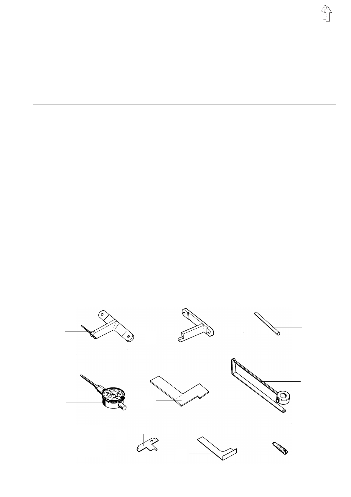
1.1 Parts of the set of gauges
The gauges li sted below enab l e t he ac c u rate adjusting a nd c he c k i ng of th e c l a s s es 1 71 an d 1 73.
The timing pi n 3 i s i n c orp or a te d i n the accessor i es of every deliv e red machine. It c an be used to lock th e
handwheel po s iti ons A - F that are required for the ma c hi n e ad j us t me nts.
Gauges Order no. Adjustment
Gauge 1 933 735 – Position of the rocker bolt in the looper drive housing
Gauge 2 933 739K – Position of the looper drive housing
Timing pin 3
(accessories bag)
Metering clock 4 171 981 – To measure the looper avoid ( width of the elliptic
Gauge 5 171 975 – Looper inclined by 89° 30
Gauge 6 933 80192 – Symmetrical looper motion
Gauge 8 933 740 – Height of the looper thread take-up cam
Gauge 9
(accessories bag)
Screw 10 933 716 – Spreading s cr ew fo r r ep lac i n g t he ar m s ha ft c ran k , e g
791 1152 – Locking the handwheel positions A - F
looper path) .
Should you already have a metering clock, you will
just need the clamping sleeve 171 984 and the
measuring pin 933 748.
’
933 758 – Thrust eccentric for the feed dog
when modifying the needle bar stroke
1
2
3
6
4
5
8
10
9
5
Page 3
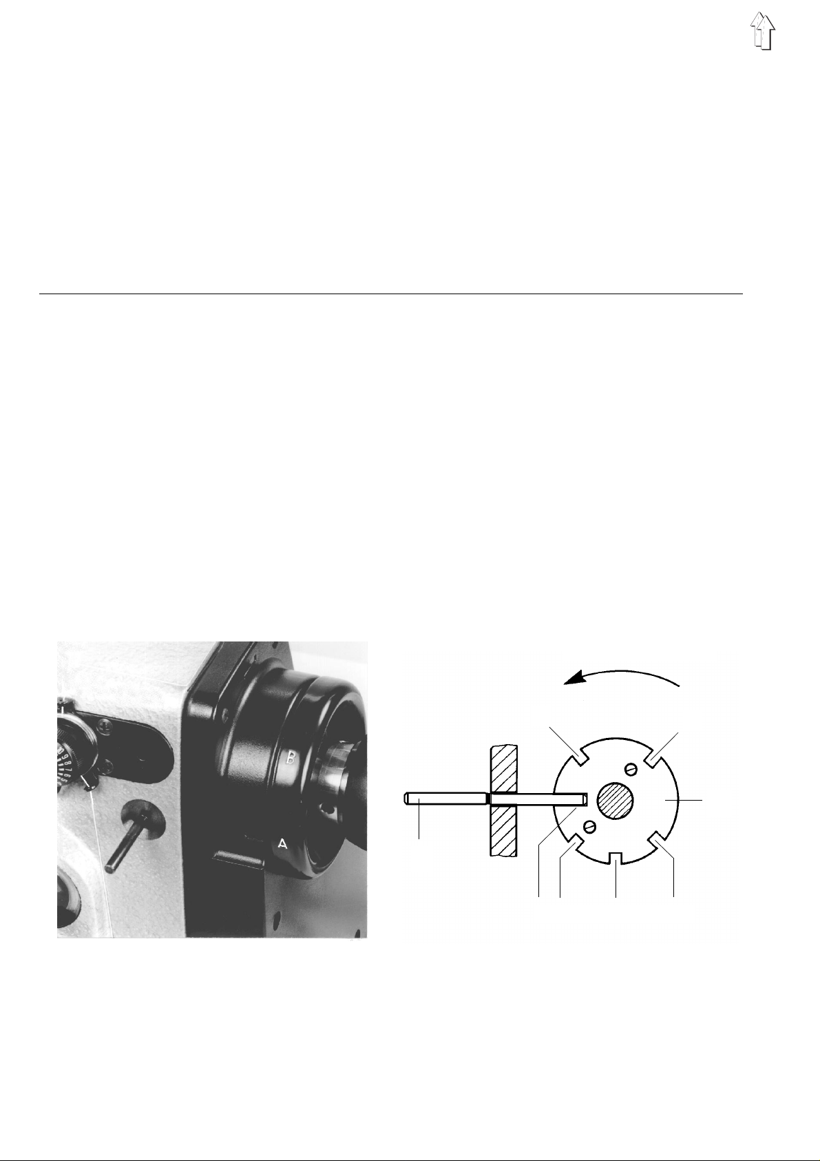
1.2 Adjustments in the different handw heel positions
For some adjustments the machine must be set in a certain position.
This position is marked by letters on the handwheel and can be locked as follows:
– Turn the handwhee l i nt o t he po s i tion defined for t he ad j us t me nt .
– Slide the ti m i ng pi n 4 i n to th e h ol e of th e machine housin g.
– Turn the handwhee l sl i gh tl y f or w ard and backward un ti l the timing pin 4 c a n b e sl i d i nt o t he r es p ec t i v e
slot of the adjustment disk 1.
– Slot A of the adjustment disk is cut out the deepest.
The depths of t he slots B - F are eq ua l .
Slot Adjustment
A
B – Symmetrical looper motion that is, when turning the handwheel in
C – Position of the lower timing belt pulley
D – Stroke and thrus t e cc en tr i c of the feed dog o n ri g ht - ha nd ma c hi n es
E – Looper thread take-up cam
F – Stroke an d t hr u s t e cc en tr i c of the feed dog o n l e ft -ha nd machines
– The deepest slot A of the adjustment disk at the upper timing belt
pulley is aligned with the groove in the arm shaft crank
reverse direction, the needle point must also be located at the centre
of the needle l ik e i n s l ot C
– Loop strok e
– Needle ba r height
– Eccentr ic fo r th e t op pu l l er feed
Operating dire ct io n
B
4
A F E D
Please note!
Depending on the needle bar stroke, the following adjustment disks are built-in:
Class / Subclass Needle bar stroke Adjustment disk
171-131110 27 mm 171 1012
173-141110 30 mm 171 1512
173-141521 30 mm 171 1512
173-161120 32 mm 171 2012
C
1
6
Page 4
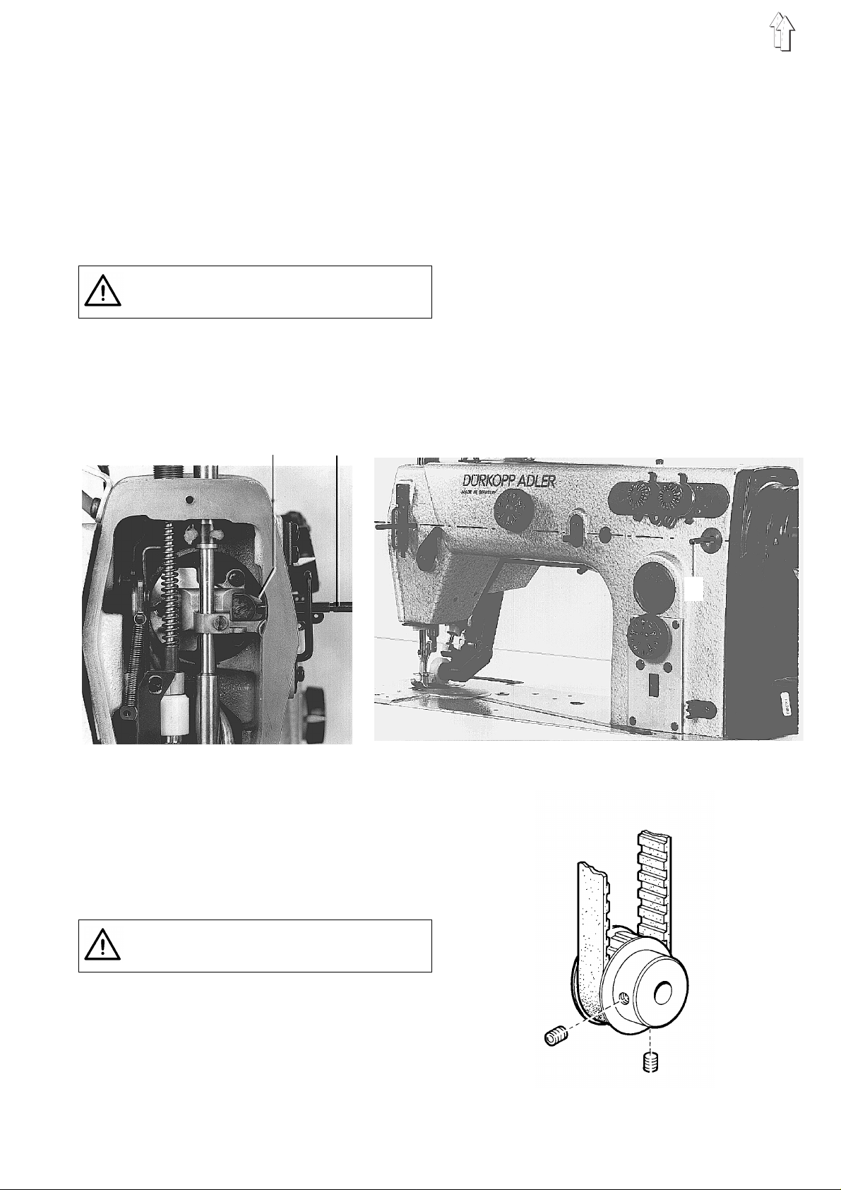
2. Adjusting the machine
2.1 Adjustment disk with respect to the
arm shaft crank
The deepest slot A of the adjustment disk 1 should
be aligned w i th th e g roo v e 2 i n t he ar m s ha ft c ran k .
(The adjustment disk must be in this posit i on to
assure that a l l ot he r adjustments to be ma de i n t he
other slots are c or re c t. )
Turn off main switch!
- Danger of injury -
Initially, check the factory adjustment using two
locking pins (as an alternative 5-mm-twist drills).
2 3
– Loosen the clamping screws of the clamping
ring. (The clamping ring is located on the left of
the upper tim i ng be l t p ul l e y ).
– Slide the pin 3 into the groove 2 of the arm
shaft crank.
– Turn the handwheel until the timing pin 4 can
be slid into the deepest slot A of the adjustment
disk.
– Push the ar m s h af t c ra nk t o t he r i gh t s o i t is
dead against the arm shaft bearing.
Tighten the screws of the clamping ring.
2.2 Lower timing belt pulley
Turn off main switch!
- Danger of injury -
When positioning the timing belt, make sure that
both screws in slot C are positioned as shown in
the drawing and are thus acce s s ibl e wi t h a
screwdrive r.
4
7
Page 5
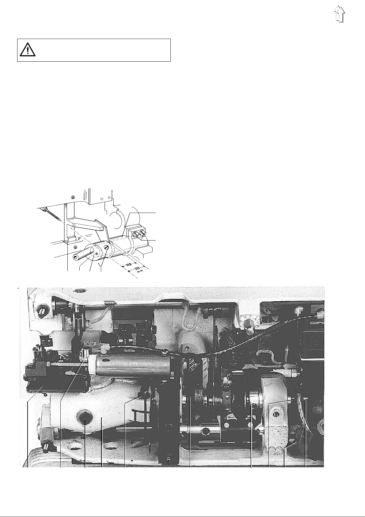
2.3 Rocker bolt for the looper drive and left bottom shaft bearing
Turn off main switch!
- Danger of inj ury -
The distanc e be tw ee n t he centre of the n ee dl e an d
the beginning of the left bottom shaft bearing 6
should be 39.8 mm and between the centre of the
needle and the end of the rocker bolt 38.8 mm.
The rocker b ol t 2 m us t be fl u s h w i th th e f ac e 3 o f
the bottom s ha ft .
– Unscrew the screw 9 and drain the oil in the
housing. Set the machine int o t he up r i gh t
position.
– Remove th e n ee dl e , n ee dl e gu ar d , l o op er
holder 8 with th e l o op er a nd th e t hr e ad
trimming device 7.
– Loosen th e cl a mp i ng s c rew 11.
– Carefully remove the looper drive housing 10.
At the same t i me sl owly turn the bo tt om s ha ft 3.
6
5
– Screw on the gauge 1, order no. 933 735.
Loosen the clamping screws 5.
– Push the bottom shaft bear i n g 6 be s i de th e
gauge. Tighten the cl a mp i ng scr e ws 5.
– Loosen the screws 4.
Check, whethe r th e r o ck er b ol t 2 i s d ead
against the face 3 of the bottom shaft.
– Remove th e g rease cover and th e o i l dri p pa n
15.
– Loosen th e e cc en tr i c 1 3, adjusting ri ng 14 an d
the gearwheel 12 .
Shift the bo tt om s ha ft 3 s u c h t ha t t he di s t an c e
between the bo ttom shaft beari n g 6 an d t he
rocker bolt 2 is 1 mm or the rocker bolt rests
against the gauge.
– Set the ad j usting ring 14 an d t he ec ce ntric 13
tight and align the gearwheel 12. Tighten the
screws.
– Check the r u nn i ng of th e timing belt on th e
bottom timi ng be l t p ul le y. If necessar y, align the
bottom timi ng be l t p ul le y.
– Screw in the screw 9.
Re-mount the looper drive housing and fill with
ESSO SP-NK 10 oil to the upper mark of the
sight glass.
– To adjust the housing, looper, needle guard and
the thread tri m me r, see sect i on s 2.4, 2.5, 2.6,
2.7 and 2.14.
2.4 Looper drive housing
1 2 3 4
7 8 9 10 11
8
12
13 14 15 3
Page 6
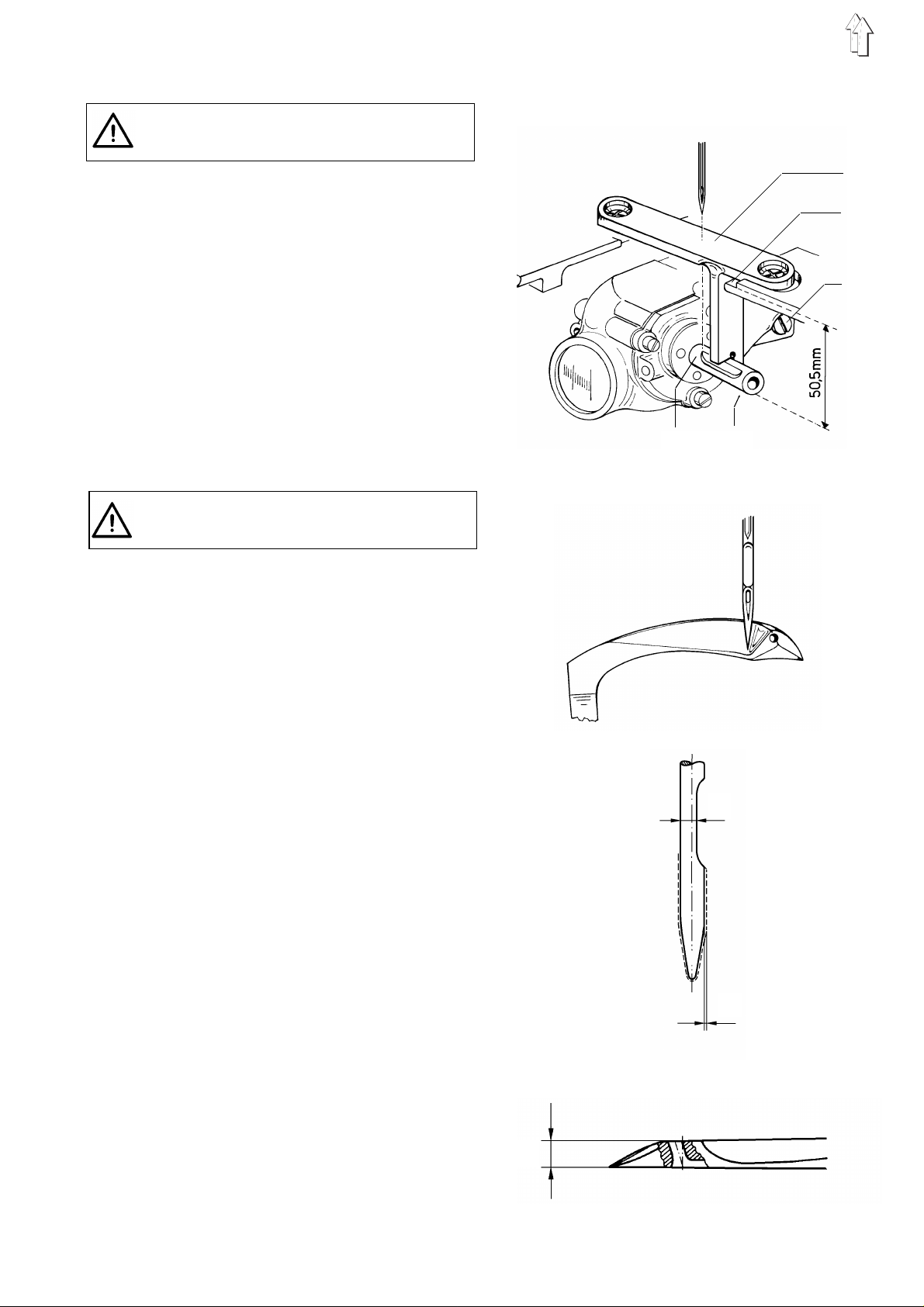
2.4 Looper drive housing
Turn off main switch!
- Danger of injury -
The needle point should point to the centre of the
looper shaft 5 and the bottom edge of the looper
shaft should be pa r al l e l to th e t hroat plate
underside.
1
2
This corresp on ds t o a di s t an c e o f 5 0. 5 m m
between the l oo pe r s ha ft bo tt om ed ge 4 and the
throat plate rest 2.
Remove the throat plate and looper holder with the
looper. Loosen the clamping screw 3.
Align the lo op er d ri v e h ou s i ng suc h th at the looper
shaft rests in the cutout of the gauge 1.
Tighten the clampin g s c rew 3.
2.5 Looper avoid (width of the elliptic looper path)
Turn off main switch!
- Danger of injury -
The looper avo i d m otion is adjust ed c or re c tl y, when
the clearanc e be tw ee n t he l oo pe r po i nt an d n ee dl e
is 0.1 mm during the right-to-left looper motion.
During the left-to-right lo op er m ot i on the point of
the descendi ng needle must rest against the bac k
of the looper, when the l oo pe r an d n ee dl e ar e
positioned as shown in the sketch opposite.
The exact amount of the avoid motion depends on
the needle system and needle size. It must thus be
computed according to the following formula:
E = a + b +0.1 + X
3
5 4
Example for a 9 34 S IN /Nm 110 needle
____________ __ __ __ __ __ ______________ __ __ __
Needle size " a" = 0.7 mm
Looper thick n ess " b " = 1.4 mm
Looper point - n ee dl e c lea r an c e = 0.1 mm
For greater ne ed l e s iz e 110 Nm "X" * = 0.1 mm
Width of the elliptic looper path "E" = 2.3 mm
*X=greater measure "a" for greater needle sizes.
X for Nm 100 = 0 mm
X for Nm 110 and 120 = 0.1 mm
X for Nm 130 = 0.2 mm
To adjust, shift the bottom shaft axially.
To the right: decreasing the width of the elliptic path
To the left: increasing the width of the elliptic path
For the adjustment see next p ag e.
a
x
b
9
Page 7
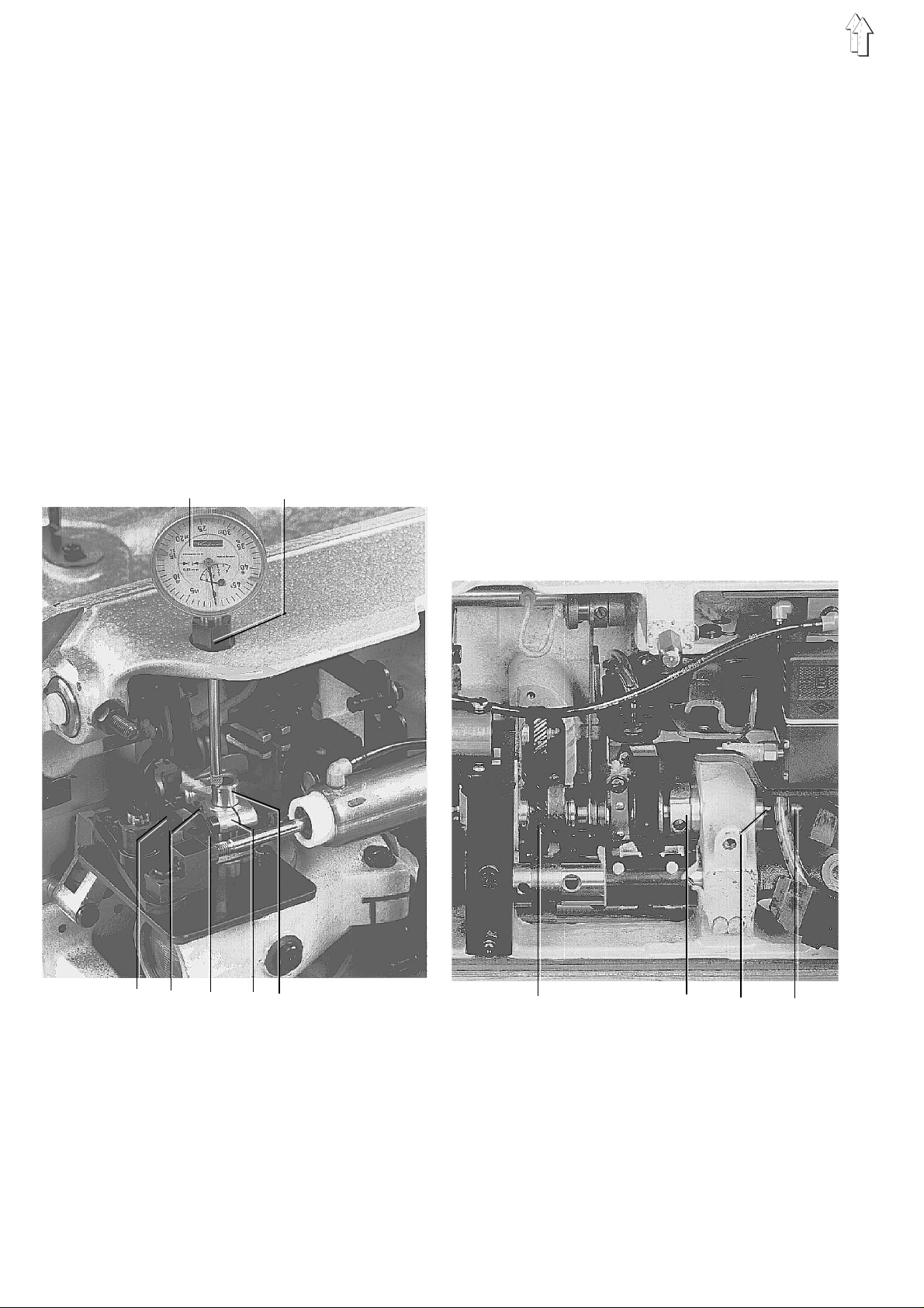
To adjust the width of the elliptic looper path proceed as follows:
– Insert a straight and undamaged needle.
Screw in the clamping bushing 2 and insert the
metering cl ock 1 .
– Turn the handwhee l to s et th e l o op er s h af t 7 at
its lowest point. Set the metering clock at the
measuring v alu e 0.
– Then turn the ha nd wh ee l to set th e l o op er sh af t
at its highes t po i nt .
Read the differen ce o n t he me te ri ng c l ock .
Should the measure not be identical with the
computed width of the elliptic path, the bottom
shaft 11 must be loosened.
– In the case of an adjustment i n a x i al d ir ec t i on
the width of the elliptic path changes with a
ratio of 1:2. When thus the bott om shaft is
shifted eg 0.2 mm, the width of the elliptic path
changes by 0.1 mm.
1 2
– Remove th e t hr o at pl a te an d f ee d d og . Set the
needle guard 3 to th e r e ar.
– Loosen the eccentric 9, adjusting ring 10 and
the gearwheel 8.
Push the botto m sh af t 11 into the respe c tiv e
direction u nt i l th e co mputed measure i s
reached.
– Tighten the eccentric 9 and the ad j ust i ng r i ng
10 so that the bottom shaft 11 is set tight. Align
the gearwheel 8 and tighten.
– Loosen the screw 5 and one of the screws 4.
Set a distanc e of 0.1 mm between th e l o op er
point and the needle by shifting the looper
holder 6 (looper point behind the needle).
Re-tighten th e sc re w s 4 an d 5 .
– Check the r u nn i ng of th e timing belt. I f
necessary, align the lower timing belt pulley.
10
3 4 5 6 7
8 9 10 11
Page 8

2.6 Symmetry of the looper motion
Turn off main switch!
- Danger of injury -
This adjustment means that the looper point is
located at the centre of the needle, when the
machine is locked either in slot C or B.
In slot C the looper point should be behind the
needle, and i n sl ot B i n f r on t o f t he ne edle.
– To enable an accurate adjustment, fasten the
gauge 1 on the looper drive housing and the
pointer 2 on the looper shaft.
– Loosen the sc r ew s of the lower timi ng be lt
pulley.
– Turn the bottom shaft such that in slot C and B
each, the pointer 2 is over the mark of the
gauge.
When turning t he ha nd wh ee l th e p oi n te r mu s t
swing to the l e ft .
– Tighten the screws of the timing belt pulley.
1 2
In operating direction - slot C
2.7 Looper in the looper holder
Turn off main switch!
- Danger of injury -
The looper face should be positioned with respect
to the edge of t he ma c hi n e b ed at an angle of 89°
30’.
In the case of two loopers, first align and securely
tighten the re ar l o op er, and then the front one.
The adjustme nt c an be ma de us i n g t he ga ug e
171 975, as shown in the figure opposite.
In reverse direction - slot B
11
Page 9

2.8 Loop stroke and needle bar height
Turn off main switch!
- Danger of inj ury -
The loop stroke is 3.5 mm. This means that the
looper poin t m us t be at th e c e nt r e o f t he ne edle,
when the needle has risen 3.5 mm from its lower
dead point by turning the handwheel in operating
direction. - Slot C of the adjustment disk.
This adjust ment must also e x is t i n r eve r s e
direction. - Slot B of the adjustment disk. See also
section 2.6 S y mm et r y of the looper mot i on .
When the lo op er e y e i s a t t he c en tre of the needle,
the bottom ed ge of the needle eye an d t he up pe r
edge of the looper eye should be level.
(see Fig.)
– Insert the ne ed l e i n to th e n eedle bar and fas t en .
– Lock the machine in slot C.
– Positio n h oo k po i nt be hi n d t he ne ed l e o n
needle center l i n e.
To do this, loosen the screw 3. Turn the set
screws 2 and 4 accordingly.
Tighten the screw 3.
– Loosen the screw 5.
Adjust the ne edle bar height suc h th at the
lower edge of t hre ad ey e i s al igned with the
upper edge of th e looper’s eye.
Tighten the screw 5.
– Set a distance of 0.1 mm between the looper
point and the c en tre of the needle by s h i ft i ng
the looper holder axially.
Tighten the screw 3. ( s ee Fi g. )
– Check symmetry of looper motion (Pos. B•
and C). See se c ti o n 2 .6 .
1
5
4
3
2
12
Page 10

2.9 Needle guard
Turn off main switch!
- Danger of injury -
When the looper point
moves to the left and
reaches the needle, the
needle point s h ou l d r e s t
against the
needle guard.
When lateral pressure is
applied to t he ne ed l e, i t
must not be po s si bl e to
press it into the path of the
looper point.
In the lowest n ee dle po sition, half of the needle eye
must remain accessible.
8
2.10 Thrust motion for the feed dog
Turn off main switch!
- Danger of injury -
To assure good stit c h t i gh te ni n g t he fe ed do g
should make a slight "additional thrust motion"
after the needle has passed its upper dead position.
The accurate adjustment is obtained in slot D using
the gauge 2 that is in the accessories bag. Proceed
as follows:
– Loosen the screws of the thrust eccentric 3.
– Lock the handwheel in slot D.
– Slide the gauge 2 into the slot 1 of the thrust
eccentric.
– Turn the thrust eccentric 3 such that the edges
of the gauge r e st o n t he s ti t ch r e gu l at or f rame 4.
– Tighten the screws of the thrust eccentric.
Make sure that th e b ot to m sh af t i s se t t i gh t.
– With maxi mu m f ee di n g l e ng th th e feed dog
must not str i k e t he ed ge s of th e t hr o at pl a te
slots.
– Loosen the sc r ew 7.
Adjust the h ei g ht of the needle guar d ac cordingly.
S
e
e
s
k
e
t
c
h
.
Tighten the screw 7.
– Loosen the screws 8.
Place the needle guard against the needle
point.
Tighten the screws 8.
The needle mu s t n ot be deflected more than is
required.
4
7
3
1
2
Attention exception!
The class 171-131110 without frame shaft, ie with
fixedly adjustable stitch lengths, is an exception as
to adjustments.
The 171-131110 can be retrofitted for the use on
hemming unit s.
Kit 171 1201 for "right-hand machines"
Kit 171 1301 fo r " l ef t- h an d m ac h i ne s"
Please note that the thrust eccentric must be
adjusted differ e nt l y on l ef t- and right-hand
machines.
"Left-hand ma c hi n e" : s l ot F
Set the firs t s cr e w s e en i n o pe r at i ng di re c ti o n o f
the thrust eccentric 3 with its lower edge onto the
upper edge of th e g au ge .
"Right-hand ma c hi n e" : s l ot D
Set the second screw seen in operating direction of
the thrust eccentric 3 with its lower edge onto the
upper edge of th e g au ge . S e e s ketch.
13
Page 11

2.11 Stroke motion for the feed dog
Turn off main switch!
- Danger of inj ury -
When the nee dl e po i nt rea c he s th e t hr o at pl a te
needle hole, the descending tooth points of the
feed dog should be level with the throat plate
surface. This position corresponds to slot D in the
adjustment disk.
– Loosen the screws of the stroke eccentric 3.
– Lock the machine in slot D.
– Turn the stroke eccentric 3 such that seen in
operating di r ection the centr e o f t he fi rs t s c rew
4 and the housing edge 2 have the position
shown in the figure. Align the gearwheel and
tighten the screws of the stroke eccentric.
– At its hi gh es t po i nt of tr a v el t he fe ed do g
should exten d 0 .8 mm above the thro at pl a te
surface.
Attention! Except of class 171-131110
"Right-hand machine": slot D
Set the first screw of the stroke eccentric 3 seen in
operating direction level with the second screw of
the thrust eccentric 1.
"Left-hand machines": slot F
Set the second screw of the stroke eccentric 3
seen in operating direction level with the first screw
of the thrust eccentric 1.
14
4 3 2 1
Page 12

2.12 Retaining spring at the looper (Only class 173-141521 with thread trimmer)
Turn off main switch!
- Danger of injury -
During the right-to-left motion of the loop er t he
needle thread l oop 1 must slide beyond the hold i ng
point 2 betwe en the retaining sp r i ng 3 a nd the
looper 4.
During the left-to-right motion of the loop er t he
needle thread l oop should be hel d at th e holding
point 2 unti l th e d es c e nd i ng ne ed l e has entered the
thread trian gl e on th e l e ft in front of the ne edle
thread loop 1.
As the needle rises to its upper position and the
looper moves to the left, the needle point should
pass the reta i ning spring at a d is ta nc e of ap pr o x .
0.5 mm.
1
To make the adjustment proceed as follows:
– Bend the retaining spring 3 so that it rests flat
against the l o op er. Make als o s ure that the
pressure is greatest in front at the holding
point 2.
– Loosen the screw 5 and shift the spring 3 to
adjust the distance of 0.5 mm.
– The pressur e of th e s p ri ng ag ai n s t t he l oo pe r
must be checked when the machine is
completed and threaded.
To do this, tilt the machine head backward and
rotate the handwheel by hand.
– Check the described stitch formation during the
right-to-left and left-to-right looper motion.
– When the ne ed l e t hread loop is not pu s he d
over the holding point 2, decrease the pressure
of the spring against the looper by bending the
spring, and when the needle thread loop is not
held by the holding point 2 until the needle
enters the thread triangle on the left in front of
the needle t hread loop 1, inc rea s e t he pr e s s ure .
4
2
5
3
2.13 Looper thread take-up cam
Turn off main switch!
- Danger of injury -
With the mach i ne l oc ked in slot E (up pe r de ad
position of the needle bar) the looper thread
take-up cam 6 s ho uld be located 5 mm ab ov e th e
carrier plate 7.
– Loosen the sc r ew s of th e l o op er t hre ad take-up
cam.
– Slide the locking pin into slot E.
– Turn the looper thr e ad ta k e-u p c a m 6
accordingly.
For measurem en ts u s e t he ga ug e 8 .
– Set the cam tight and tight en th e s c rews.
8
7
6
15
Page 13

3
4
10
5
1 4 2 13 16
14 13 12 11 9
7
6
16
9 8
18
17
Page 14

2.14 Thread trimming device
Turn off main switch!
- Danger of injury -
During the trimming process the looper thread
behind the looper and the rear thread of the needle
thread loop mu s t b e c a ug ht by t he po i nt 7 o f t he
movable knife. See sketch.
4. Mounting and end positions of the thread
trimmer
– Unscrew the screws 2 and initially remove the
movable knife.
– Position th e t hr e ad tr im mer such that the k n i fe
holder 13 fits over the ball lever 16.
Tighten the screws 1.
5 6
7
1. Removing the knife
– Unscrew th e s c re w s 2 and remove the mo v ab le
knife 4.
– Then unscrew the screws 1 and remove the
whole thre ad tri m me r ass e mb l y.
2. Manual trimming test
– Initiall y, fasten the m ova bl e k ni f e 4 by
tightenin g t he s cr ew s 2 s li g htly.
The screws 2 should be approx. located at the
centre of the elongated hole of the knife.
– Align the point 7 of the movable knife with
respect to the notch 6 of the stationary knife 5.
Tighten the screws 2 securely.
– Make a trimming test with thread.
If the thread is not trimmed properly, the edges
must be checked or new sharp knives are to be
installed.
– Set the movable knife in cut t in g position by
slightly turning in the pressure screw 3.
The smooth mo ti o n o f t he knife must be
assured.
– If necessary, align the movable knife in cutting
position with respect to the stationary knife.
3. Thread clamping sheet
The thread c l am ping sheet 10 shou l d sl i g ht l y
clamp the thread end to assure a secure seam
beginning.
If the clam ping sheet holds th e t hread too
tightly, seam pucker may occur at the seam
beginning.
– Screw the piston rod 12 into the block 11 until it
is flush with the face of the block.
– If the piston rod is moved into its right end
position, t he edge 13 of the kni fe ho l de r an d
edge 14 of the plate should be flush with each
other.
Adjust the end position of the cylinder 9
accordingly (hexagon spanner 2.5 mm) using
the self-locking set screw 8.
– As a pre-adjustment fasten the movable knife
with the screws 2 such that
a) the point 7 points to notch 6 and
b) the cutti ng ed ge s of th e k n i v es o v er l a p
approx. 1 mm.
– During sewing make a trimming test with the
shortest an d l o ng es t s ti t ch l e ng th.
– If necessary, slightly correct the position of the
point 7 so that the threads are caught securely.
5. Thread puller for the looper and needle
thread
During thread trimming the thread tensions are
opened and the thread pullers 18 for the looper
and needle thread are activated. The pulled
tension-free thread is ne ed ed fo r s ec u re s t i tc h
formation at the next seam beginning.
Just the amount of thread needed should be
pulled, as t hi s d et er m i ne s the length of the
thread end at the seam beginning.
– The thread puller 18 is stepped.
By adjusting the stopper 17, more or less
thread can be pu l l ed .
17
Page 15

1 2
3
4
3
9
7
5
1 mm
8
6
5
6
18
Page 16

2.15 Sewing foot stroke
Turn off main switch!
- Danger of injury -
The height of the sewing foot stroke depends on
the needle bar stroke of the respective class and
the needle system used.
With the needle system 934 the sewing foot stroke
is in general 5 mm, and with the needle system 933
it is in general 10 mm.
In the case of higher adjustments and a passage
for thick fabrics make sure that the needle bar or
the needle block must not strike the sewing foot.
Initially, unscrew the stop screws 1 and 2 by some
turns.
The sewing foot sole must rest on the throat plate.
To do thi s, tu r n t he ha nd wh ee l ac c o rdi n gl y.
Adjusting the foot stroke of hinged feet (top
puller feed)
– Place an object, the thickness of which
corresponds t o t he s tr o k e, be tw ee n the sewing
foot sole and throat plate.
– Loosen the sc r ew 9.
Adjust the block 5 on the cloth presser bar so
that the support sheet 4 can just be swung
unhindered under the support nose 7.
– Align the sewing foot with the needle and
tighten the s cr ew 9.
– Remove the object.
When the sewing foot rests on the throat plate,
a distance m us t be be tween the block 5 a nd th e
sleeve 6.
Adjusting the foot stroke of hinged lever feet
– Initiall y, reduce the s ew i ng fo ot pr e s sur e by
screwing the pressure sleeve 3 upwards.
– Loosen the sc r ew 9.
Lower the cl ot h presser bar unti l t he s ew i ng
foot sole re s ts f l at on th e t hr o at pl a te .
– Adjust a distance of approx. 0.5 mm between
the block 5 and the sleeve 6.
– Align the sewing foot with the needle and
tighten the s cr ew 9.
– Re-tighten the pressure sleeve 3.
Make sure that the pressure of the spring is
adjusted clearly higher than that of the hinged
lever foot.
The lowest pos i t ion of th e h i ng ed l eve r fo ot i s
thus determi n ed by t he s l ee v e 6 .
Screw in the s c rew 1 until the dis ta nce between the
angle 8 and the block 5 is approx. 1 mm. The
sewing foot sole must then rest on the throat plate.
Limit the pa th of th e k n ee l eve r bl o c k by s c re wi n g
in the screw 2. - One should just be able to swing
the support sheet 4 unhindered under the support
nose 7.
When the mac hin e i s e qu i pp ed wi t h t he pneumatic
sewing foot lift, the stroke of the cylinder 10, ie the
sewing foot st ro k e, i s to be l imi t ed by the stop
screw 11 accordingly.
10 11
19
Page 17

2.16 Setting the stitch lengths
Regular stitch lengths
If eg a stitch length of 3 mm has been adjusted at
the dial, 11 stitches on thin cardboard mu s t b e
equal to 30 mm.
Loosen the screw 3.
Insert a drift into the hole 1 and turn the frame
shaft 2 accordingly.
1 2
Condensed stitch length of the bottom feed
The minimum condensed stitch length is 1.2 mm.
While adjusting the stitch length, raise the puller.
Make condensed stitches on thin cardboard by
pressing t he bu tt on at th e m ac h i ne he ad .
11 stitches must be equa l to 12 mm.
To mak e t he ad j us t me nt , i n s er t a s cr e wd r i ver i n to
the slot 5.
Loosen the screw 6 and set the stopper 4 higher or
lower accordingly.
3
6 5 4
20
Page 18

Condensed stitch length of the top puller feed
The puller should always feed slightly more than
the bottom feed.
The material i s t hu s te ns i o ne d, th er e by preventing
seam pucker.
When the condensed stitch length of the bottom
feed is eg 1.2 mm, the feed of t he pu l l er i s t o b e
adjusted to 1.3 mm.
Lower the pulle r.
Make condensed stitches on thin cardboard by
pressing th e b ut to n a t t he s ewing head.
11 stitches must be equal to 13 mm.
Adjust the stopper 8 accordingly.
Reduce the sewing foot pressure such that thin
cardboard can j us t pa s s be tw ee n t he s ewing foot
and feed dog.
The lock nut 7 and the stopper 8 are also accessible w i th sc r ew ed on to p c o v er p l at e.
8 7
21
Page 19

3. Setting the top puller feed
Turn off main switch!
- Danger of inj ury -
3.1 Synchronisation of the bottom feed and top puller feed
The bottom feed and top puller feed should be
synchronise d. T he pu ll er m ot i on , ho we v er, must
never be completed earlier than the feed dog
motion.
Thus, the mat eri a l i s te nsi o ne d b et we en th e s e wi n g
foot and the puller so as to prevent seam pucker.
When the machine is locke d i n sl ot E an d the
grooves of the traction rod 1 and the eccentric 2
are congrue nt , t he ab ov e ad j us t me nt i s completed.
– Remove the bobbin winder cover.
– Loosen the screws of the eccentric 2 just
enough that i t c a n b e t ur n ed on th e a r m sh aft
with minimum effort.
– Insert a screwdriver into the groove 3 of the
eccentric.
– Turn the handwhee l to bri n g t he machine to the
position E.
– Tighten the scre ws o f t he ec c e nt r i c 2.
To check t. synchronisation proceed as follows:
– Set the dials for the bottom feed and top puller
feed eg at 3 mm.
– Place two thin cardboard strips under the
sewing foot an d p ul l e r s uc h th at th ei r ends are
adjacent.
– Turn the handwheel. - The distance between
the ends must not change.
– If necessary, correct the setting of t. puller dial
so as to assure synchronous feeding motions.
– Loosen th e g rad ua te d plate of the dia l an d
re-attach suc h th at 3 mm is indicate d.
3
2
1
1
2
3.2 Distance between the puller and
needle
The distance between the puller and centre of the
needle should be 30 mm.
Make sure that the automatically raising puller
does not strike the sewing foot.
To mak e t he ad j us t me nt , l o os e n t he s c rew 4.
4
6
22
30 mm
Page 20

3.3 Raising stroke of the puller
Upper end position
The raised puller must not strike the sewing foot.
Turn the bolt 8 such that its slot is vertical.
Limit the stroke of the piston in the cylinder 9
accordingly using the self-locking set screw 7.
To do this, use a 2.5-mm-Allen key.
Lower end position
After the vulcollan puller has lowered onto the
throat plate, the rocker 6 must still be able to
oscillate 2 mm, before the stopper of the hand lever
5 reaches it s en d position. The ma te r i al is thu s
slightly tensioned by the touching down puller.
Loosen the loc k n ut 10 an d turn the thread ed pi n 11
accordingly.
Attention!
Steel pullers must not rest on the throat plate. The
distance bet w e en th e p ul l e r an d p l at e s h ou l d b e
approx. 0.2 mm.
3.4 Puller pressure
The puller pressure can be modified by adjusting
the lever arm for the cylind er f orc e an d c a n t hu s be
adjusted to the respective ma te r ial .
Loosen the sc r ew 13 . C y l i nd er i n
arrow-indicated direction A = higher pressure
arrow-indicated direction B = lower pressure
5
4
7
8
9
10
11
12
3.5 Fabric keep-off plate
The distance between the puller and the fabric
keep-off plate 12 should be as small as possible.
To prevent the material from getting caught in this
gap, the dist a nce needs to be corre c te d d ep en di n g
on the abrasi on of th e p ul l e r.
On machines without thread trimmer the fabric
keep-off plate at the same time serves as trimming
knife for the thread chain.
3.6 Timing belt tension
The timing belts should be tensioned so as to
assure the accurate transmission of the step
lengths of the puller.
A too great belt tension may result in excessive
wear and tear and malfunctioning.
13
B
A
23
Page 21

3.7 Replacing the puller
The following pullers are available for the diverse applications:
Vulcollan puller 9-mm-wide standard on the machine Order no. 933 5725
Vulcollan puller 16-mm-wide asymmetric Order no. 933 5737a
(in the acce ss or ies bag)
Steel puller 9-mm-wide 1-mm-roof-toothed Order no. 933 5736
Steel pull er 1 5-m m- w i de 1-m m-r o of - to ot he d Order no. 93 3 5 73 7
Steel pull er 1 5-m m- w i de 2-m m-s a w- t oo th ed Or d er n o. 93 3 5 73 8a
The asymmetric vulcollan puller that is in the
accessories bag enables to vary the position of the
puller with respect to the seam or fabric fold.
This puller i s to be used on tw in- n ee dl e ma c hi n es.
To rep l ace the puller pro c ee d a s fo l lows:
– Remove th e n ut 14 us i n g a 7-mm-fork spanne r.
(Attention l/h thre ad!) A t th e s ame ti m e hol d the
other end of t he ax le 15 by means of a
screw-driver.
– Steel pullers must not touch the throat plate.
The distance should be 0.2 mm. Therefore,
correct the " Lo w e r en d p os i t i on " of th e p ul l e r as
described in section 3.3 accordingly.
14
15
24
Page 22

3.8 Raising and lowering functions of the puller
Various functions for the puller can be selected at
the Efka V730 c on tr o l pa ne l .
This is done in the parameter F190 / code no.
FFF 001 to 003, preferably according to subclasses
for machines w i th or without thread tr immer. 003
does not contain any functions for double
chainstitc h ma chi n es .
001 preferabl y f or t op puller feed wi thout thread
trimmer with the following functions:
1. At the seam end the puller always remains
lowered to h old the thread chai n.
The thread chain is trimmed by the trimming
knife of the fa bri c k e ep -off pl a te.
2. When the sew i ng fo ot i s l i ft ed wit hi n th e s e am
the puller is raised as well.
3. When sewing is continued, the puller lowers
either immediately or after a delay, depending
on the entere d n um be r of stitches. The
numbers of st i tc h es 0-254 are set in pa r am et er
F191.
3. The puller lo wers at the seam beginning and af ter the sewing foot lift within the seam after the
number of sti tc h es b et we en 0 and 254 entered
in parameter F191 has been sewn.
4. The puller ca n b e r a is ed or lo we r ed wit hi n or
outside the seam at the touch of a button at the
sewing head .
For programming proceed as follows:
1. Hold the key P pressed.
2. Turn on main switc h . - Th e c o de no . C 0000 is
displayed.
3. To enter the "technician level 1" input the Efka
code no. 1907 usi n g the keys 1.... 0.
4. Press key E . - Th e p ar a me te r no . F 10 0 i s
displayed.
4. The puller ca n b e r ai s ed or l o we red wit hi n th e
seam at the touch of a button at the sewing
head.
002 preferabl y f or t op puller feed wi th thread
trimmer with the following functions:
1. After thre ad tr i m mi n g t he pu l l er i s ra i s ed
automatical ly.
2. When the sew i ng fo ot i s l i ft ed wit hi n th e s e am
and the threads are trimmed within the
material, the puller is raised.
5. Enter the parameter no. 190 using the keys
1...0.
6. Press key E. FFF 001, FFF 002 or FFF 003 is
displayed. O ne of th e c o de nu mb er s c a n b e
selected using the + or - key.
7. Press key P twi c e .- Th en th e ad j us t me nt is
completed.
8. Attention! Always sew a seam with thread
trimming or s ewing foot lift . O n l y then the
entered adjus t me nt i s me mo r iz ed .
25
Page 23

4. Adjusting the synchronizer
Prior to the adjustment check whether the
synchronizer is properly fastened on the
handwheel flange.
When the machi n e i s lo ck ed in sl o t A , th e ma rk 11
should be located exactly opposite the groove 12.
This is pos i ti o n 0 , w hi c h i s the starting po int that all
factory se tt i ng s of machine positions depend on .
The machine positions are registered by the
synchroniz e r in s t ep s ( inc r e me nt s ) of 0.7° and are
displayed.
One complete revolution is subdivided into 512
steps (incr e me nt s ).
st
1
position
The machine should stop when the looper has
safely picked up the loop that is, the needle should
rise from its lower dead position until the looper
point has moved to the left by approx. 3 mm
beyond the needle.
This corresponds to the number of increments 214.
101110
12
8
9
7
nd
2
position
Needle bar i n i t s up pe r de ad po s i tio n.
This corresponds to the slot E of the adjustment
disk or the nu mb er o f in c r em en ts 3 84 .
For programming proceed as follows:
1. Hold the key P pressed.
2. Turn on main switc h. - Co de no . C 00 00 i s
displayed.
3. To enter the "technician level 1" input the Efka
code no. 1907 using the keys 1....0.
4. Press key E.- The parameter no. F 100 is
displayed.
5. Enter the p ar a me te r no . F 170 using the k eys
1....0. Press key E.- Service routine 1 (Sr1)
appears. Press key F.- Position 0 is displayed.
6. Turn the handwheel by one complete revolution
in operating direction and lock in position A
using the enclosed timing pin. Press key P
twice.
7. Press key P.- F 170 is displayed.
8. Press key E twice.- The servie routine 2 (Sr2)
and F 171 are displayed.
9. Press key F. - Position 1 and the set number of
increments a re d i s pl a yed. Set the numb er o f
increments 2 14 usi n g the + or - key.
10. Press key E.- Position 2 and the set number of
increments are displayed. Set the number of
increments 384 using the + or - key.
11. Press key P twice. - Now the adjustment is
completed.
12. Attention! Always sew a seam with thread
trimming or s ewing foot lift . O n l y then an
entered adjus t me nt i s de fi n i te l y me morized. If
no seam is sewn , t he ad j ust me nt i s los t wh en
the main switch is turned off.
26
 Loading...