

Page 1
adler
I,
'
166
.
,.
-
Gebrauchsanieitung
Directions
Mode d'emp~
· lnstrucciones para su uso
for
oo
use
..
Page 2
50
l ,
':i'
,e
1\\
~ !
49
I
I.
I
I
I
I
38
I
I
15
~
.
39
""
l~lflt=
~ 45
40
:~
47
46
37
3
\0.111
~
111
\
lff
44
43
36
r,.._
I
11
::::::,,
~
-
I
bu
~
I i' I I lg
_,
54
51
6
G
A,
~03
166-I:0
10
Page 3
Gebrauchsanlellung
Auch wenn Sle
Gebrauchsanleitung aufmerksam durchlesen und
Nur dann
Der folgende Text
Weicht
Gebrauchsanleltungszusatz.
Die Abblldungen zum Text linden Sia au!
Bille
beachtenl .
die
Um
In
kelt
1.
wiihrend
2.
bel
3. bel Dauerbelastung
4.
bel groBer Stlchliinge
5.
·bel schwlerlgen Arbeltsvorgiingen .
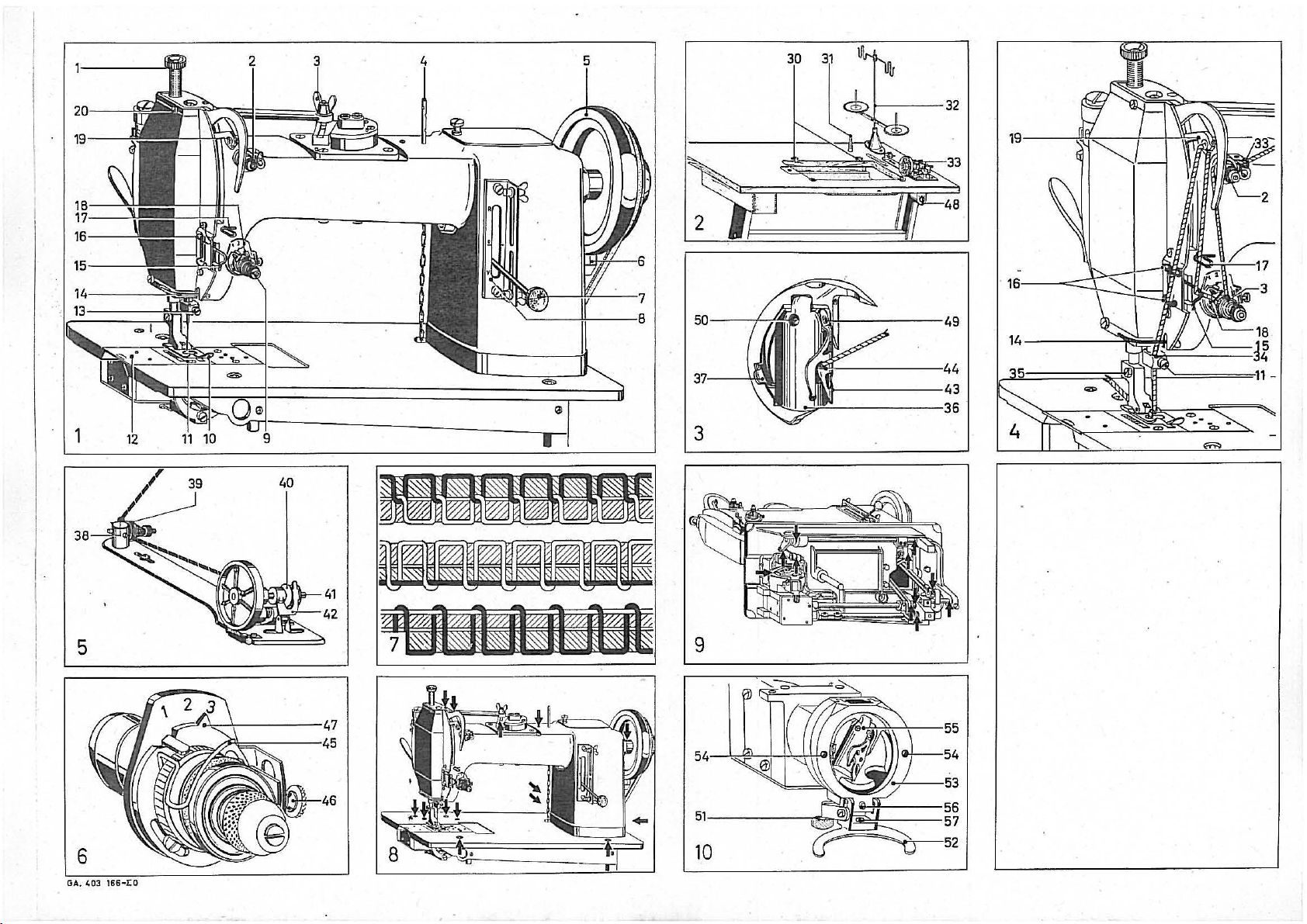
Heuptbedlenungselemente
1 NiihfuBdruck-Elnstellschraube
2 Oberfaden-Vorspannung
3 Stlchbrelten-Elnstellmutter
4 Garnrollenstlft
5 Handrad
6 Riemenschutz
7 Stlchstellerhebel
8 Stlchstellerskala.
9 Oberfadenspannung
10
NiihfuB ·
Auspecken
1.
In
2. Niihmaschlne, Arbeltstlsch und
3.
Bel Beschiidlgung
Komplettleren .
1. Im Normalzubehor beflndllche Scharnlere
slacken und festschrauben. .
2.
Niihmaschlne au! fertlgmontlerten Arbeitstlsch bzw. Gumml-Unterlagen
Abblldung-2, setzen.
3.
Obertellstiitze
4.
Garnstiindur
5.
Kellrlemen au! Handradschelbe und Motorschelbe euflegen.
Der Kellrlemen hat dann
Zusammendriicken In der MIiie
Relnlgen
1.
Kopldeckel, Stlchplatte losen und entfernen.
2.
Alie
befrelen.
3.
Kopfdeckel und Stlchplette eufschrauben.
Oberfaden eln!Udeln
1.
Den von der Garnrolle kommenden Oberfaden durch den Fadanfilhrungs·
bugel Im Garnstiinder
2.
durch den Garhrollenstlft
3.
durch die Faden!Ohrun~
-
4.
llnksherum zwlschen die Vorspannungschelben 2
_5. 111,
6.
Ober
7.
unter d·en FedenlOhrungshaken
8.
durch die 'Fedenfuhrung
9.
van rechts
· hiichster Stellung seln) ·
10.
durch belde Osen
11.
unter
12.
In
die
13.
und von vorn nach hlnten etwa 8 cm durch des Nadelohr fl!deln.
Nadel und Garn
1.
Verwenden Sia das Nadelsystem
2.
Regel
Klemm! der Faden
Hat
nehmen.
3.
Fiiden
Nadel
1. Nadelstange
2.
Nadelbefestlgungsschraube
nach unten aus der Nedelstanne zlehen.
3.
Neue Nadel
stange einsetzen. .
4.
'Nadelbefestlgungsschreube
NiihfuB euswechseln
1. Schraube
2.
NiihfuB van der StolfdrOckerstange abziehen.
3.
Neuen Ni!hfuB
Spule herausnehmen
1.
Nadelstange In tlefste Stellung brlngen (Handrad nach vorn drehen).
2.
Spulengehiiuse
feder
In
dleser Stellung kann
warden.
Unterladen aufspulen
1.
Unterfaden van
Abbildung
2.
Zwischen
3.
Spule
Spuler
4.
Spule elnlegen
1. Ge!Ollte Spule so
li
nks abwicke lt.
2.
Spule
3.
Heraushiirigenden Faden durch den Schlitz bis
feder
4.
Spulengehause
schnappt.
Stlchliinge elnslellen
1.
Stlchstellerhebel 7 au! Skala
Kurzerer Stich. Stlchstellerhebel nach unten stellen
2.
Sebald Sia den Hebel
Maschlne
eln
erfahrener Niihmaschlnenkenner slnd,
Isl
elne elnwandfrele Funktlon gewiihrlelstet. ·
gilt
die
Bedlenung der Unterklassen von dar Grundaus!Lihrung ab, slehe
Lebensdauer der Meschlne
folgenden Fallen reduzlert warden:
der
starkem Material
Gegenwart des Oberbrlngere
slchlbaren Telle
mal rechtsherum um
die
Fadenenzugsfeder
die
Faden!Ohrung
Bohrung des Nedethallers
!Or
die Sliirke
der
Faden zuvlel Platz In der lengen
auf
auswechseln
35,
37
nach
die
40 au!
schaltet slch automatlsch aus.
In
ausgeschwenktes Spulengehiiuse einschleben und festhalten.
43
In
rOckwarts. ·
nur fur die grundsatzllche Bedlenun~
der
ROckselte disses Blattes.
zu
verliingern,
ElnlaUfzelt
166-1
sofort
In Gegenwart des Oberbrjngers reklamleren.
31
In
Tlschplattenloch slacken.
32
und Kraflspuler
die
mil
elnem Plnsel von Rostschutzfett und evtl. Schmutz
4,
33
die
nach
Materlalstarke abstlmmen.
In
mil
Abblldung
In
vorn schwenken.
6,
fiideln. .
Spannungsscheiben
die
(Unterfaden elnfi!deln) ·
das Fadenaustrlttsloch
17
links
In
das Fedenhepelauge
der
FadenfOhrung
14
der
Nadel: • ·
In
der lengen
hochste Stellung brlngen (Handrad nach vorn drehenJ.
langer
Rllle
3,
losen.
umgekehrter Relhenfolge anschrauben.
36,
Abblldung
die
der
Garnrolle durch
Spulerwelle
In
die
llnke
In
Ausgangsstellung zuruckdrucken,
uber
11
Stlchplatta
12
Grundplattenschleber
13
Nedelbef.-Schreube
14
FedenfOhrung
15
FedenfOhrungshaken
16
FadenfOhrung
17
Faden!Ohrung
1B
Fadenanzugsfeder
19
Fadenhebel
20
Kopfdeckelbef.-Schraube
die
Verpackung
Zubehor au! Transportscheden prufen.
In
Nl!hmaschlnen-Grundplatte
33
aufschrauben.
rlchtlge Spannung, wenn
gerede noch berOhrt.
Abblldung 4,
Spennungsrolle 3
18
15
. ·
16
34
328.
Rifle'-
sliirkere Nadel verwenden.
Rllle
13,
Abblldung 1, nach
nach vorn so hoch wle mogllch In Nadel-
13
festdrehen.
3,
durch kriiftlgen Druck euf
Spule·ohne Schwlerlgkelt herausgenommen.
die
Faden!Ohrungsose
39
!Ohren und um
41
slacken und Hebel
Hand nehmen, daB slch
44
etwa 8
cm
6,
Abb.
1,
nach oben (bis zur
o hlnaus nach oben schwenken, naht die
sollten
die
Empfehlungen beachten.
der
sollte
die
Niihgeschwlndlg-
aul
Beschiidlgung prOfen.
er
slch balm
19
(Fadenhebel
- schwiichere Nadel
llnks
drehen und Nadel
die
38,
die
Spule
42
andrOcken.
der
Faden nach
unler
die
Spannungs-
nach auBen fi!deln.
Q]_s
es horbar
= Langerer Slich.
Sia dlese
Adler
muB
Schnapp-
40
0)
166.
In
wlckeln.
eln-
stellen
30
NahfuBdruck elnstellen
1. Elnstellschraube
Rechtsherum
2.
Der NahfuBdruck
daB
euch bel hoher Nahgeschwlndlgkelt des Material elnwandfrel trans-
wl
portlert
Fadensnzugsleder elnstellen
1.
Die Fadenenzugsfeder
Niihdlcke elngest
2.
1st
elne Elnstellung erforderllch, dann:
Schraube
Zeiger
47
Zeiger
47
Schraube
Zurn Nllhen vorberelten und nllhen (Gered1llqinllhen)
1.
Spannung (Volt) au! dem Stromzahler
Motorschlld
2.
ZufOhrungsstecker ml! dam Netz verblnden.
3.
Motor durch Scheller 48, Abblldung
4.
Slfchbreltenmutter
stellen und festdrehen (Geradstlch). .
5.
Unterfaden heraufholen (Oberfeden festhalt
'Varn drehen).
6.
NiihfuB luften.
7;
Bel.
de
Fiiden nach hlnten unter den Niihf
8.
Niihmaterlal unte r
9.
FuBtrltt nlederdrOcken. Maschlne naht.
Je welter
Maschlne.
10.
Drehrlchtung
" zu drehen.
11.
Maschlne·ohne Sto
12.
Nech
dam Ni!hen Mot
Zlckzacknllhen
1.
Stlchbrelten-Elnstellmutter 3, Abblldung
nach
vorn =
nach
hlnten = gr6Bere Stlchbrelte (Zlckzackstlch).
2.
Elnstellmutter 3 festdrehen.
Vergessen Sia dies nlcht,
Niihens van selbst verstel
Fadenspannung lindern ·
1,
Nach kurzer Stracke geni!hte Nahl prilfen.
Abblldung 7 oben
Abblldung 7 mllte
Abblldung 7 unten = Oberfadenspannu ng
2.
Oberfalfen·seannu ng mogllchst nlcht veriindern. Sia 1st vom Werk aus !Or
normales Nahgarn elngestellt.
elner
Ver
trotzdem erforde rllch, die Obertedenspannung
Abblldung
Rechtsherum
Linksherum
3.
Unterfadenspannung mogllchst nlcht veriindern.
Falls jedoch ertorderllch mil Schraube
Rechtsherur11
Llnksherum
Beachten Sia Jedoch,
gelost
wlrd.
·Nach
der
Relnlgen und
1.
Nach
liingerer
2.
Motor
3. Kopfdeckel, Stlchplatte und Grundplettenschleber entfernen.
4.
5.
6.
·7.
8.
9.
10.
Sollten noch lrgendwelche Unkle rhelten bestehen, bltte Vertrete r oder Fach-
berater anfordern.
Bel ROckfragen Im Werk bl
1. Lieferdatum
2.
3.
abschalten. Netzstecker entfernen.
Alie slchtbaren
Bel ll!ngerem Stlllstand
Telle
llchen
Maschlne
Schmutz ebputzen . .
Nahmeschlne
ertorderllchen Olstellen an. Nur
Verwenden Sia
Balm Relnlgen und Olen der Schlffchenbahn gehen Sia wle
51,
Hebel
unten). .
Schlffchenbahn-Deckel
schlffchen
Die Jetzt slchtba re Schlffchenbahn
tuch elnolen.
Barrelschlffchen, Schlffchenbahndeckel elnsetzen. Deckelfeder zuklappen,
dabel darauf achten,
Klassenbezelchnung
Obertellnummer
1,
Abb.
1,
= NiihfuBdruck starker. Linksherum = NiihluOdruck schwiicher.
soil
rd.
ell
46
losen
au! .,1" st
au!
.,3"
stellen bel extrem
46
festdrehen.
Obe
relnstlmmen.
der
FuBtrl
der
Meschlne pr!ifen. Handrad mun
kle
' seannung zu schwach.
Verstellung deshalb lmmer erst
1,
drehen:
= Stiirkere Span nung
(Versc!illngung kommt mehr nach oben)
= Schwachere Spannung
(Verschllngung kommt meh r nach unten)
= St!irkere Spannung
= Schwiichere Spannung.
Sia slcherl
Verstellung Schraube
Olen
Betrlebsdauer oder Stlllstand Niihmeschlne relnlgen.
Telle
geben.
mlt
engehobenem NiihfuB kurze Zell laufen
clan
. Ole Pfelle
nur
Abblldung 1
55
aus der
drehen:
bel entsprechendem Niihmeterlal so stark sel
45,
Abblldung
t (Stellung
elle
n bel extrem
3,
Abbltdung
cjen
NiihfuB lege n und NahluB senken.
tt
durchgedrOckt wlrd, desto schneller
ff
nur dann lauf en lessen, wenn NiihfuB engehoben
or
durch Schaller
lnere Stlchb relte (Zlckzackstlch)
lt.
= Verschllngung
= Oberfedenspannung
spannung
daB
vor
die
Spannungsteaerschraube
.
van Niihruckstiinden relnlgen.
der
Maschlne etwas Pet roleum
6,
isl
2).
1,
de elch sons! die Stlchbrelte wiihrend des
zu
der
Verstellung
50
vom Werk fur eine mittlere
dOnnem
dlckem Material
2,
losen, nach vorn bis zum Anschlag
Isl
starli.
wleder
Material
muB
mil
den Angaben au! dam
elnschaiten.
en
und Handrad elnmal nach
uB
legen.
slc
h auf den Niihenden
48,
Abblldung
1,
losen und verstellen:
rlchtlg.
zu
zu
die
49,
Abblldung
festdrehen.
2, abschellen.
schwach, oder Unterfaden-
stark, oder Unterfaden-
Einfadelung prOlen. Isl es
zu
verst
ellen,
G,
elnstellen.
die
Slcherungsschraube so
vor
an
niiht
die
da_nn Kn
dam Herausfellen.
alle
beweg-
!assen.
der
Abblldungen 6 und 7 geben die
elnlge
Tro,P.fen
unser Hoci1lelstungs-Nahmasch nenol MR
0,
herunterdr
55
Bah
·
daB
tt
e angeben:
Ocken
van FOhrungsstlften
n nehmen.
mit
Nase
56
genau In Bohrung
an lade !Jlstelle geben.
(Deckelfeder
54
abheben und Barrel-
elnem olgatriinkten sa ubBfen Putz-
3.
folgt
52
klappt nach
..
57
zu Ilagan kommt.
vor:
n,
1st.
opf
Directions for' use
Even
if
you are a sewing machine expert,
operating instructions carefully and to observe all the reccomenda tlons give n.
Only then can satisfactory operation be guaranteed.
The following text
Where operation
supplementary operating Instructions. The text illustrations
-on the reverse of this sheet.
Please
notel
In
order to extend the
reduced In the following cases:
1.
During the running-In period.
2.
When processing thick material.
3.
During long-term continuous operatio n.
4.
When large stitch lengths are used.
5.
When doing compli cated wor k.
applies only to the basic operation of the Adler
of
the sub-classes diff ers fr
Ille
of the machine, the sewing speed should be
it
Is necessary to stu
om
that of the basic Mode'I see
will
dy
these
166.
be found
9
Page 4

~aln
Components
, 1 Presser t
2 Needle thread pre-tensioning
, 3 S!ilch width ad Justing nut ·
4 Spoof
1
5 Handwheel
1
16 Belt guard
7 Slltch
i8 Sli!ch
9 Needle thread tension
10
Presser
Unpacking .
1. Check the packing.
2. Check sewing machine, worktable end accessories
may have
3.
In the case
of the forwarding agent.
Erecllon
1.
Fit
the hinges supplied as standard equipment
I base
plate
'2. Place the machine on the assembled worktable
Fig.
2.
3.
Flt
the top
4
..
Screw
'
5.
Flt
the Vee-belt onto the handwheel and
has the correct tension when the two runs
when pressed together.
Cleaning
1. Slacken the head
2. Using a
1
· components. .
1
3,
Screw
I -
Threading .
.
1. Pass the needle thread from the
In the
1
1
2.
Through the
3.
Through the thread guide
1
,4.
Anti-clockwise between
5.
11/
i
limes
1
8.
Over the take-up
/
7.
Underneath
8. Through the thread guide
9.
From
, highest position), ,
10.
Through both eyelels of the thread
i
1.
Underneath
12.
Into
the bore
i.
3.
And
from front to rear approx.
I
Needle and Yarn
1.·
use
needle system.328.
2. Rule
tor
If the thread
too
much clearance
·
3.
Adapt needle thread
Replacing
1'. Move needle
yourself). · ·
2.
Turn
needle setscrew
draw
the needle
3.
insert
groove
4.
Tighten
lleplaclng
1. Slacken
2.
Withdraw
3. Screw
llemovlng the Bobbin · ·
1.
Move needle
yourself). , ·
2.
Swing
spring
In
_this position the
Winding
the
1. Thread
' 38, Fig. 5. . · .
2. Pass between the tensioning
a.
Fit
the
lever
r The Winder
Inserting
1.
Grip
the wound
to the left. .
2. Jnsert the
3.
Pass the thread end through
·
spring
by
approx.
4.
Return the
audible
J1dju1tlng Iha Stitch Length
1.
Rotate stitch regulator lever 7, Fig. 1, as
Clockwise = increased presser
Anti-clockwise
'
2.
According
be sufficient
hlgher
Adjusting
I. The take-up
thickness (position
2.
If
any adjustment is ·required, proceed
Slacken
For extremely
For extremely thick materiel set
Tighten
166-1
ool
adjusting screw
holder
pin
regulator
regulator
on
spool
rlghtto
new needle
42.
the bobbin (threading the bobbin thread)
_the Thread Take-up
lever
scale 18 Thread take-up
toot
for
damage In
occurred
the
soft
down
the
clockwise around the tensioning
needle gauges:
the· Needle
in
front.
needle set~crew 13.
the
screw.35,
presser
on
new presser
bobbin
37.
Bobbin thread
the
bobbin
43, thread
click.
sewing speeds. · -
screw
screw
In transit.
of
damage,
and
section support
spool
brush, remove anti-rust grease and any
_ head cover and tl)roet plate.
needle lhread
holder.
spool
the
left
the
of
jams
bar
prasser foot
bar
bobbin
will
bobbin
3".
bobbin
to
the material used, the presser
to
spring
lmmedla!ely
screw
down.
holder
cover
and throat plate and remove.
pin 4 (Fig.
33,
the
sprlng
·1a,
thread
guide
17,
Into the take-up lever eyelet
thread
guide
the needle
in
the long groove use thicker needle; If the thread has
in
the long
to
thickness of materiel.
Into
Its
highest
13,
Fig. 1, In en anti-clockwise
ln
a downward
es
fer
as
Fig.
3.
foot
from
foot
to
Its
lowest position (rotating the hendwheel towards
casing 36,
·
bobbin
thread from the reel through the thread
40
onto the
cut out automatically.
bobbin
with
Into
the swung-out
It
fnto the thread
case
to
= reduced presser
ensure
that
45,
Fig.
2).
46.
thin
materiel set
46.
11
unils
31
into the tabletop hole.
32
and the power
4),
pre-tensioning
hook
14,
holder
it
wlll
the
in
Fig
can
discs
winding
your
the
Its
the materiel Is
Spring
6,
Throat plate
12
Base plate
13
Needle setscrew
14
Thread guide
15
Thread guide
16
Thread guide
17
Thread guide
19
Take-up lever
20
Head
the
prescence
bring
such damage
motor
will
spool
through the needle thread bracket
discs
railer
15,
guide
16,
34,
3"
through the needle eye.
groove
use
thinner
position
(rotating hendwheel towards
direction
presser bar.
the Inverse order.
. . 3, forward
be easily removed.
Initial
foot
ls set at the works
Indicator
indicator
from the
go
Into
the
by
39
end
wind
spindle
41
left
hand so that the thread
bobbin
slot
as·
far
es urtderneeth the tension
outlet
hole
position
follows:
pressure.·
foot
pressure.
setlsfaclorlly
as
follows:
47
47
cover se_tscrew
winder
needle
and
until
toot
to "1".
to
slide
hook
spring
of
the forwarding agent ..
for
any damage which
to
the attention
lnlo
the sewing machine
or
on
rubber pads
33. .
pullles.
The Vee-belt
Just touch
19
smartly depressing the snap
around
case and retain.
44
"3".
at
the centre
dirt
from all visible
· ·
2,
3,
(with
the
lever
needle.
direction
needle
bar.
bar
with
guide
the
bobbin
lightly
depress the
end
pull
1t outwards
It engages
pressure should
fed even
for
a medium sewing
end
the
will
with
30,
in
Its
with-
long
eyelet
40. -
unwind
en
with
Preparation
1.
2.
3. Switch on the· mot
4.
5.
6. Reise the presser toot.
7.
8. Place the sewing materiel underneath the presser .foot
9.
10.
11.
12.
Zig-zag Stitching · ,
1. Slacken the stitch width
2. Tighten adjustrng
Changing
1.· After sewing e
2. If
3.
Cleen·lng.,and Oiling .
1. After continued operation
2.
3.
4.
5.
6'
.
7.
8.
9.
10.
Should there
When sending enqu
1.
2.
3.
Top
for
The voltage
the
Connect
Slacken the stitch width nut
and retight
Pull up the
the handwheel towards your
Place both threads towards-the rear .underneath the presser foot.
Depress
depressed, the faster the machine
Check the
rotate· towards the operator. .
Allow
raised. . ·
After sewing, switch
Forward
Rearward
Please remember to do this, In
not
Fig.
Fig.
thread tension. . . . .
Fig.
thread tension. · . . ·
at
been set at the works
Before carrying out any
the threading. Should It be necessary,
thread tension, turn
Clockwise = Increased )ensl
Antr-clockwlse
Do
Should
Clockwise = Increased tension. ·
Anti-clockwise
Before carrying out any adjustment,
sleckend.
On
must be' cleaned and
Switch off th·e motor and remove the mains
Remove the heed cover, throat
Remove.any sewing residua from all
If
· amount of paraffin to
Allow
Remove any
011
Figs. 6 end
Only use
When
Depress the lever
Reise the shuttle track
barrel shuttle
Using e
be visible.
Insert the barrel shuttle end
making
Date
Class designation.
Operation end Sewi
on
motor
change wh'iie sewing. · ·
7,
7,
7,
ell
not
the current meter l?hpuld coincide with the rati ngs
plate. ·
power
supp
ly
or
by means of the switch
en
(Straight s
bobb
_in thread (ho
!he
pedal. The machine will now sew. The furthe
direc
tion
of rotation
the machine to run
off
= smaller stitch
=
larger
stitch
nut
3. .
the Thread Tension
short feng
top = cor
centre = Insufficient
bottom
change th e
rect
loop
= excessive
possible, do no! change
it
be necessary a
tor
the-button
= reduced te
bobbin
= reduced tension.
This
completlori
the machine hes not been used
the machine. Tt,e
of
section number.
prevents t
of the adjustmen t retlghten the screw
oiled
machine to run
7.
our
cleaning
clean
sure that the
still
delivery.
ell
for a short
dirt
.
lubrlce
Apply
only
heavy duty sewing machine o
and
oiling
51,
Fig.
55
from its track.
oil-saturated
lug
be
any-
doub!s, plaase consult your agent
ir
ies to the works, please stat
ng
(Straight
plug
to.th
e mains. .
3,
Fig. 1, turn
tit
ch). . .
ldi
ng on
self
by
w
of
the machine. Th e handwheel should
with
out a
ny
the
motor
_ by means
adjusting
adjus
fter
he
movab
cover
nuf 3, Fig. 1,
widlh
(zig-zeg,stltch). ·
width
(zig-zag s
order
th '
of se!J.m
ing.
needle
needle
the
·standard yarns. · .
tment,
9,
Fig
on
(laoping
nsion
(loop Ing moving further .down).
thread tenslort unless absolutely necessary.
ell, adjust
tension
or
protrac
.
pla
te end base plate
le
parts. :
while
tlng points
e few
drops
the s.
huttle
10
(the cover
53
from the
cloth,
oil
shuttle track cover. Close t
56
engages exactly
sllt
ch sewing)
48,
Fig;
It forward
to
the.needle thread end turning
one rotat1on). ·
ill'
operate.
niefer
tit
to ensure that the stltch·
, check the seam.
thre
ad -tenslori
thread tension
needle
therefo
efler
. 1,
as
moving
by
means of the
the
Jocking screw
spring
ted standstill periods the machine
visible perts.
for
some length of time apply e
with th
are indicated by
to
each lubricating
path, proceed
spring
gulde"pl
the shuttle track which will now
2.
as
-en
iai only wit
of
ch).
thread tension.
re, always
ell,
follows:
screw from dropping out.
plug.
il
in
h th~ presser
the switch 48, Fig. 2.
11nd
adjust
or
excessive b
or
insufficient bob
slert
to
<;he
nge the needle
higher up).
50
50.
slide
e presser
MR3.
as
52 wlll
swing down
ns
54
end remove the
the
bore
e:
•
· Mode d'emplol
MAme sl vous Illes
attentlvement cette
recommendations donnees.
un
fonctlonnement lrreprocheble. .
drez
Le texte suivent se
En
cas au
base, nous vous prions de
Les Illustrations se trouvent au
lmporlentl
Le longevlte de
dans
·fes cas suivants: .
1. Pendent
2. Pour les matleres epelsses
3.
En
cas
4.
Pour ies longueurs
5.
Pour
_les
Prlnclpeux tll6ments de regleg11
1 Vis
de
du
pied
2 Pretension
3 Ecrou de reglege
largeur de
4 Cheville porte-boblne
5
Volant
Gercte-courrole
6
7 Ragle-points
8 Echelle
9
Tenslpn
10
Pied de
D6ballage
1. Deballar
irreprochebit1.
un
speciellste
notice
la
refere seulement
manipulation des sous-classes
le
machine sera
le
rodege .
d'un
service contlnu
du
Ill
poln!s
de
dlfficlles
le
d'elgullle
pour
operations
reglege pour
de machines II coudre, vous devr
pour
!"usage
C'esl
a cette seule
blen
voulolr lire
versd de
accrue
polnl
extrllmes
166-1
presslon
la
a main
du
regie-points
du
Ill
d'eiguille
biche
le
machine en presence du
at
f"entretlen einsl qu'en observer les
condition
au
service .fondamentel de
dlffere
de
le
calla feuille.
sl
le
vltesse de plquege est redulte
11
Plaque II
12
Gllssiere du plateau
13
Vis de
Gulde-Ill
14
15
Crochet
Gulde-Ill
·
16
17
Guida-
18
Ressort de tension du
19
Tendeu r
20
Vis
de le
llvreur
celle
mode
d'amploi supplemenlaire.
aiguille
fixati
on
guide-Iii
Iii
de
fll
de
fixa
tion
tAte
et
s'essurer de l'embellege
on
tar
as
It
will
go-
d lower the foot.
'r
the pedal Is ·
·
as
follows:
wld
th
will
obbin
This has
by checking
screw
49,
Fig. 3:
must be
.
toot
,ralsed.
the
arrows In
poin
t.
follows:
he
de
cover
57.
or
en expart.
·
que vous
l'Adier
de
la
l'elgullle
).
spring
lez
lire
ciasse
166
Iii
du couvercie
foot
bin
smell
obtle
de
,
n-
.
Page 5

2. S'assurer que
endommages pendant
3.
Reclamez immediatement
Completer
1.
Placer !es charnieres
de la machine et les vlsser.
2.
Placer la machine
en caoutchouc
3.
Meltez l'appui porteur
4.
Adapter par vlssage le porte-boblne
5. Pla
cer
La tension de
presses
Nettoyage
1.
Devisser le couvercle de
2.
Llberer toutes !es pieces visibles de la. gralssa
sieres eventuelles a !'aide
3.
Visser
Enfllage du
1.
Passer le
2.
par
la
{l,
par le guide-Iii
4.
de
la
5.
11/,
tour
6.
sur le ressort de tension
7.
en:dessous du crochet gulde-11115
a.
par
le
9.
de drolte a gauche dens
(le
lendeur
10.
par las deux
11.
en-dessous du guide-Ill 14,
12.
per
le
13.
et de l'avant a· l'arrlera par le chas de
d'envlron 8 cm.
Algullle
et
1. N'utllisez
2.
Regles pour
Utlllser
Utiliser
ralnure.
3.
Cholslr
Remplacemant de
1.
Amener
(faire tourner
2.
Tourner
vars
le
3.
lntrodulre une nouvelle algullle,
profondement qua possible·.
4.
Resserrer
Remplacement du pied
1'.
Desserrer
2. Enlever le
3.
Placer un nouveau pied en pro.cadent dens
la
Enlever
1.
Amener
volant
2,
Faire plvoter en avant a bolts a canette
le ressort
dlfflcultes.
Boblnage du
1.
Enfller
fig.
5.
2. Passer
canette
3.
Placer la canette
4.
Le devldolr s'arn'lte automatlquement.
Mlae en place de
1.
Prenez la canette remplle dens la main gauche de·mimlere qua
se deroule vars
2.
Placer
3.
Passer
dans le trou
4.
Pousser
encliquete.
Reglege de
1. AJuster le regle-polnts 7
plus courts,
AJuster le regle-polnts 7
2.
AussitOt qua le ragle-points est· ajuste en haut en-dessus du
pique en
Ajuster
la
1.
Tourner la vis de reglage 1, fig.
vars
la
la
vars
2.
La
pression du pied
que la
de
cas
du ressort de tension
Reglage
1. Le ressort de tension de
grosseur de
2.
SI
le
reglage
desserrer
ajuster
ajuster
la
serrer
Preparatlfs precedanl .
1.
S'assurer qua
indications de
2.
Branch·er
3.
Mettre le moteur en marche par commutateur
4.
Desserrer
jusqu·a
5.
Faire ven
to
ur
vars
6. Ele
ver
ni
la machine, nl la table, nl !es accessoires
le
transport.
au
llvreur !es dommages eventuels.
se
trouvant dans las accessolres normaux au plateau
sur
la
30,
la courrole sur
la
l'un
contra
le couvercle de
Ill
d'algullle
Ill
en provenance de
chevllle 4 (fig.
gauche, entre las dlsques d!l tension 2
presslon du
le
33
a drolte autour de la roue de tension 3
guide-Ill
17
de
Ill
oelllels
trou du porte-algullle
fll-
que
le
le
cholx
une
algullle
une
elgullle
le
Ill
d'algullle
l'olgullle
la
barre a
le
la
vis de fixation
bas.
la
vis
de
la
vis
35,
pied
de la barre presse-etoffe.
canette
la
barre a
a main en avant/.
37.
Dens cette position
Ill
de
canette
le
Iii
de
canette en provenance de
le
Ill
entre las dlsques
40.
la
la
la
canette dens
le
bout
de
44 a l'exterleur
la
boite a canelle dans sa position
le
longueur
arrlare.
drolls
= prasslon
gauche = presslon mains forte
matlere
soil
vltesse elevee.
matler
dolt
la
vis
46,
l'l
ndex
47
!'Index
47
vis
46.
la
tension (volt) lndlquee
la
la
fiche du cab
l'ecrou
la
butee
en
ir
le
Iii
de
sol
le volant a main).
pied.
table de travail montea ou blen
fig. 2.
31
dans
le
trou de la table.
32
et
la
poulle du volant a main et
courroie est
l'autre
dolt
systems
plus
plus mince si
alguille
volant a main en avant).
fixation
fig.
algullle
40
sur
canette (enflfage du
gauche.
Iii
par
de
pied
dolt
toujours entrafnee lrreprochablement, egalement en
e moyenne (position
iltre
sur
..
sur
,,3,.
le
plquage et plquege (points rectlllgnes)
plaque du moteur.
de reglage de
avant et le serrer (points rectlllgnesj,
canette (retenlr le
cor
se
touchent legerement.
la
tats alnsl qua la plaque a
d'un
plnceau.
la
tats alnsl que
4)
du gulde-11116
de
modlfle
1.
la
de
Ill
18
l'oelllel
se trouver dens sa position
34
.
d'algullle
la
grosseur des algullles:
forte
sf
salon
la
grosseur de
dans sa position
13,
fig. 1, vars
la
13.
3.
dans sa position la plus basse (tourner le
d(!
l'axe de
devldolr
la
bolts A canette plvotee
la
fente jusqu'en dessous du ressort de tension
et lalsser ressortlr d'env. a cm.
point
sur
l'echelle a vars
sur
l'echelle 8 vars
1.
plus
forte
etre aussl forte - salon
de
fll
Ill
45,
fig.
II faut:
·
en ces de matleres. partlcullerement minces,
en cas de matieres partlcullllrement grosses,
le
d'allmen
la
le
rects sl !es deux cotes
la
boblne
par
du tendeur de
328.
le
Ill
se co Ince
le
Ill
a trap de
la
longue rainure etant en avant, aussi
36,
la
canette peut
la
tension
39
41
Ill
de cenetle)
6,
a ete regle des
2).
sur
tatlon
I!
largeur de point
Ill
d'algullle
devidolr
sur
antlroullle
plaque a
le
guide-Ill du porte-boblne
Ill
19
la
plus
l'algullle
dens
Jeu
la
matlllre a coudre.
la
plus haute
gauche
et
l'ordre
inverse,
fig.
3,
par forte pression sur
lltre
boblne
par
et
i'enrouier
et pousser le
et
la
d'orlgine
le
haul (ju_
le
bas = points plus longs.
la
matlllre a coudre -
l'usine
le comptelJr correspond
la
prise de courant du reseau.
48,
fig.
2.
3,
et fa re tourner
n'ont
sur
las coins
de canettes
la
poulle
de
la
courrole
algullle.
et de pous-
algullle
,
haute)
dont
II
dolt
la
longue ralnure.
dens
la
longue
rellrer
l'algullle
enlevee sans
le
guide-Ill
auteur de
levier
42.
le
maintenlr.
Jusqu
a ca
squ'a
O)
= points
o,
la
pour une
fig. 1,
i'ajuster
eta
33.
motrlce.
ressoi11r
38,
la
Ill
qu'elle
machine
aux
d'un
48
7,
Tirer les deux bouts de Iii va rs l'a rrlere dessous
B. Placer
la
9.
Appuyer
qua la pedale sera poussee plus fortement.
10.
Verifier
tourner vers
11.
La
prealablement releve.
12.
Couper le
Couture e points zig-zag
1.
Dess
en avant = largeur de poi
en arrlere = large
2.
Serrer
Observer a
qua l_a largeur de point se deregle pendant la couture.
Modification
1.
Executer quelqu
fig. 7 en haut
fig. 7
du
fig
de canette trop falbl
2.
Eviler - sf poss Ible - de modifier
ajustee des
prealablement l'enfllage correct. SI la modif
d'alguille
vars
vars
3.
E~lter - sl possible Indispensable, tourner la vis
vers
vars
Avant la modifica
qui empache
serrer le
Nelloyege et grelssage
1.
Apres un servic e contlnu ou am'!t pl us long de
nettoyer.
2.
Couper le
3.
Enlever
plateau. ·
4.
Nettoyer toutes las pieces des poussle res.
5.
En
petrols a toutes las pieces
6.
Faire marcher la machine quelques
7.
Enlever des lnip urltes.
8.
Huller
las trous correspondent s. Ne mettez qua quelques gouttes d'
chaque trou.
9.
N'utlllsez que no
10.
Pour
proceder comma
appuyer sur le levi er
enlever
Barrel
chiffon Imbibe d'hulle. Monte r la navette Barrel et le couvercle de
couslere.
exactement dans
S'II
ya
representant au blen s'adresser dlrectement
a lndlquer: ·
1.
Date de llvralson
2.
Designation de la classe
3.
No. de
matiere a
sur
la pedale et piquer, La machine plquer a d'autan t plus vl te
la
directi
machine ne
Ill
. 7 en bes = tensi on du
cas
encore des choses qui son! peu clalres, dema nder la visits
l'opera
dolt
circuit
errer
l'ecr
ou de reglage
l'ecrou
de reglage
ce
qua
de
lo tension
= f
au
milieu = tension du
de canette trop forte.
l'u
slne po
est Indispensable, tourner le bouton
la
drolte = te nsion pl us forte (boucles plus hautes)
la
gauche = tensi
la
drolte
la
la
le
55
la
= tension plus forte
gauche = tension ma ins
la
vi~ du ressort de
!rein
d'e
circuit
le
couver
d'un
erret plus long
machine a coudre, les fleches des
nettoyage
le
couvercle
de la courslere, huller
Ancll
queter le ressort du couvercle. Le nez 56 doit s'adapler
tAte.
lnstrucciones para
Aunque sea usted
leer atentamente estas
de este modo queda garantlzado el fu
El texto slgulente solamente es vall
maqulna.
construcclon fundamental, debera
suplementarias.
Las
reproducclones correspo ndlentes al texto las encontraran a
de esta hoja.
Observecl6n lmportantel
Para prolonger
•.
de costura durante los cases slgulentes:
1.
mlentras dure el rodaje,
2. cuando los ma!erlales seen gruesos,
3.
durante el trabajo permanents,
.
4.
al coser con puntadas largas y
5.
al realizer operaclones
Elementos de
1
Tornlllo
del prensatelas ·
2 Tension prevla dei hllo supe r
3 Tuerca de ejuste de
de puntada
4 Esplga portacarrete 15 Corchete gufahllos
5 Volante de mano
6 Proteccl6n
7 Palan ca de regulacl6n de
puntada
8 Palanca del regulador de
puntadas plancha frontal
9 Tensl6n del
Desembalaje
1.
Comprobar, en presencia del portador, si esta danado el embalafe.
2.
Veri
flc
coser,
3.
En
caso de averlas, .rec amar inmedlatamente en presencia del portador.
Ccimplelar
1.
lntroduclr y
las blsagras qua se encuentran entre los accesorlos
un
En
cuanto el manejo de las su
la
duracl6n
manejo prlnclpales
de ejuste de la preslon
de
la correa 17 Gufahilos
hilo
superior
ar
sl se han det
la
mesa de traba /o y las accesorlos .
atornllla
co
udre dessous le
on
de rotation de la m
trice.
pique r sans matlere a coudre qua sf
par commutateur 48, fig.
nt
ur
le
es
points et ve
or
mation
ti
on de le t
crou
et enlever
cle
ire hull
et
suit:
le
conoceder
lnstrucclopes
plus petite (poi
de point pl
3.
serrage de l'ecrou
de
Ill
correc
Ill d'algullle trap falble, ou blen tension
Ill
e.
trou 57.
la
d'al
ur
des fils a coudre normaux, II faut verifi
on
molns forte (boucles plus bass
de
modif
49
ension
50.
la
du bras, la plaque A a
de
mobile
e de
quail
le
gralssage
51,
fig
. 10 (le ressort
de
la
couslere
su
uso
de
de
la
maqulna tendril. que reduclr
dlffcil
de
ior
anchura
la
eriorado
r fuertemente en
pied
et abalsser
ach
ine. Le volant a main do
2.
de
la largeur de po
us
rifier
ts des boucles
gullle trap forte , ou blen tension du
ier
, fig.
fo
la
fiche de contact.
la machine mettre quelques gouttes de
s.
ta
de
ensulte la coursiere visible a
maqµlnas de
da
nclona
do
consulter
es.
la
durante el transporte
nt
grande (point zig-zag).
soil
vralment effectue pour eviler
la couture.
la
tension du
icat
la tens
ion du Ill de canette. Si
3.
rte
II faut desserrer le
tension a se dev
lgullle
poi
nts a
pied
Illustratio
MR
3.
la
courslere
52
se
53
des chev
a
l'
uslne. N'oub ll
coser
empleo y
para el manejo fundamental de
bcl
166-1
10
11
12
13
14
16
18
19
20
segulf
mlento de la mliqulna.
asses sea
las
inst
Pie de costura (prensatelas)
Plancha de aguja
Tapa
-co
Tornlllo
Gufahllos
Gufahllos
Muelle de tension del
Tlrah
ilos
Torni
llo
la
cama de la mliq uln a de easer
le pied.
le
pied.
le
pied a ate
int
3,
fig
·.
1,
et
Elle a ete
tension du
es)
d'evrou
taut
re du
et
7 lndlquant
hulle dans
.
le bas).
l'elde
d'u
er
pas ·
al
de
la
la
'4!.lelta
la
vel
ocldad
la
cama
hilo
la
le
cela
la
fau
la
n
zig-z
ag)
Ill d'algullle.
ion de
la
9,
fig. 1.
!rein
isser. Aprils le .reglage,
la
machine II
el
le
gllssle
sieve.
ns 6
de
la navette II
pile va
rs
ill
es
54
et retlrer la navette
experlmentado deblera
sus consejos. Solo
dlstinto
rucclones de empleo
rredera de
de sujecl6n de la aguja
de sujecl6n de
la
mliqulna de
normale: .
lt
regler:
f1I
er
Ill
50
t
d'un
la
est
Page 6

I
i
2.
Colocar
la
a
goma
3.
lntroduclr
1
plancha
Atornlllar
·
s:
Colocar
,
del
: Dlpha
; ramales
1
lmplar
1
t
t·
Soltar
. Con
n
de
i:
~.
Atornillar
nhebrar
'j·
Pasar el
portacarrete, ·
.
por
r .
por
,. . dando
i'· dando vuelta y
!.~
hllo
.
por
I. .
por
l.r.
par
;, . de derecha a izqulerda,
situado en su punto mas alto), ·
.
par
.
debajo
I .
fatroducilindolo,
I. . se enhebra,.seguldamente,
?.
unos 8 cm.
guja e
1
· . Sfrvase
t
. Regis para el grueso de
rl
SI
· una
,
SI
-·
agufa mas delgada.
t . Servlrse
~-!ambler
l
Sltuar
7
·,
el
8
·[.
Glrar
9
· y,
lntroduclr
.
0
estalladura
·
1
:1•
amb~i:ii~~jiii~
car
fa
3. • Sltuar
qua
Bascular
1
fuertemente
1'.
En esta
2
·
oblnar
. Pasar el
3
figure
par
'.
4
canllla
I .
Colocar
palanca
1
. El devanador
2
3
,locer
,
.
tomar
se
1
pasar
afuera y retenerla,
2
enhebrar
hendldura, haste debajo
salida
emp_
al
ustar fa
2.
Glrar
hacla
3
hacia
4 Para un material
sera
impecablemente aun al trabaJar
1
ustar
2. El
para
SI
Soltar
colocar
el
Apretar
1 eparar para hacer la costura y coser (costuras rectllfneaa)
. La
plaqulta
Unlr
Conectar
Soltar
ad el ante hasta el·
Sacar
ha
Aflojar
Colocar
Extender
Plsar
Cuanto
maqulna de easer
30,
completamente montados,
el apoyo de
de
mesa. .
el portacarrete
la
correa cuneiforme sabre la
motor.
correa
estarli bien tensa, cuando, al
en
el
media,
y retirar la plancha frontal y
un
pineal,
todas las
el
la
el
3,
el
debajo
el
debafo de
hilo
Bl
hilo
aguja
el
hllo
la
ag
volante de mano). · ·
hacla
tlrando
cenllla
case el volante de mano),
el
hUo
entre fos
la
canllla
con
desenrolle
la
ujar,
encontrarse. en su
longltud
la palanca
la
la
suficlentemente
el
muelle
muelle
un
deb
iera
fndlce
tensl6n
la
el
cla
adelante
el pedal. La maqulna cose.
qultar la.
pieces
las planchas, frontal
hllo
hilo,
espiga
guiahllos
la
vuelta a
muelle
guiahllos
del
utilizer
Se ,aprisiona
mas gruesa.
Ilene
de
uJa
la
barre
de
lp
la
barre
hacla
poslcl6n,
Inferior
hilo
5,
luego,
40.
la
42.
la
canllla a la
el
del
hllo
haste
derecha - mayor presl6n
lzqulerda
de tensl6n
grueso
efectuarse un afuste, se procedere
el
tornlllo
el fndlce
47
el
tornlllo
del
clavlja
el
la tuerca de anchura de puntadas
hllo
el
pie
fas h
el
mas
vislbles.
superior
qua
parte
portacarrete
33, ·
la
media
de tensl6n
del corchete gufahllos
17,
los
dos
gufahllos
luego,
el sistema
demasllldo
hilos
de
de
aguja
la
lzqulerda
la
nguJa, sacarla
mas
poslble
lar~a mlrando
de aguja
afuera
el
muelle
la
Inferior,
discos
canllle
40
se
desembraga automatlcamente.
(enhebrar
mano
lzqulerda
hacla
la
cabo
de
44,
dejandolo
qua
se
de
puntada A
de
regulacl6n de las puntadas I,
- manor presl6n
de
costura determlnado,
de
tensl6n
de
costura medlano (poslcl6n
46,
47
en "1" pa ra materlales extraordlnarlamente
en el "3" para materlales extraordanarlamente gruesos.
46.
en
voltios
motor.
ile
allmentacl6n
motor
por
lope
lnferfor
el
volante
de
costura.
llos
hacla
material
se
plse
el
en
la m·
esa
de
la
cabeza
de
32
en
el
se
logra
hacerlos
grass
antlrobfn
'y
de eguja.
.
del
carrete,
4,
figura
izqulerda,
14
conformldad
por
hacla
la
derecha,
dei
hllo
18,
por
el
agujero
corchetes
en la entalladura
y
en
la
en
el
en
el
agujero
en
el
de
aguja
aguja:
sltio
su
punto
tornillo
hacla
la
hacla
guiahllos
ojo
en
barre
adelante.
trabajo o
como
se
maqulne
devanador
la
entre
15,
la
con
de
motor
pole
del
querer
tocer
.
de
aguja.
y;eventualmente,
por
la
palanca
4,
los
discos
por
el
19
del
16,
del
sujetaaguja 34,
de
la aguja,
328.
iarga
entalladura· large -emplear
el grueso de/
mas
alto
sujecl6n
abaJo
de
de
aguja,
ve
en
31
en
el
33.
volante
Junter
gulahilos
rodillo
tlrahlios
defandolo
de
la
(glrando
de
la
la
barre
la
nueva
aslentos
la
figure
agujero
de
de
tensi6n
de
(qua debe
aguja -
material.
hacla
aguja
de aguja.
ii~:,~:;;:':(~~o
en
su
punto
mas
bajo
(glrando
hacla
la
capsule
de
canllla
36,
llgura
de encafe
canllla
que
de
en el
ef
lzqulerda, ·
capsule
hllo
olga enca/ar claramente,
poslcl6n
grande para
del
del
del
med
y apretarla (puntada rectlnfnea).
(su)etando
de
pedal, tanto mes rapldamente case
37.
puede sacarse
parte del carrete,
tensl6n
39 y arrollandolo
lirbol
portacanllla
·
hllo
Inferior) .
la
canllla
de
la
mlsma
qua
cuelga
del
muelle
de
colgar
unos 8 cm hefilB afuera,
pr
glnal.
del pie
del pie
qua
con
hllo
hilo
45,
figure· 6,
contador
de
atras y
costura
lo
del
mane).
debe
de
corrlente
Interrupter
el
hllo
debajo
debajo
sin
por
Ilene
basculada
h11cla
afuera, pasandolo,
tensl6n
de
de costura.
la
presl6n
equal sea transportado
velocldades
este ajustado, en
colndidlr
e la red.
48,
3,
figure
superior y girandcruna
del
pie
del
pie
3,
la
manor
el'
corchete
varies veces
41 y preslonar
de
modo
qua qua
hacia
43,
por
el
la
capsule
figure
costura
del
mayores.
2).
de
la manera
·
con la
flgura
' 1.
1,
correrla
de
costura.
y ba)arlo.
de
2.
de
la
mano y la
ios
dos
la
sucledad
del
prevla
tensi.
6n
del
ester
colgar
utlilzar
adelante
13,
flgura
aguja
con
la
persona
preslonando
dlllcultad.
gufahllo
en
la
con
la
el
hllo
par
de
canllla,
de costura
la
fabrlca,
slgulente:
llnos
lndlcada
hacla
vuelta
la
maqulna.
de
la
agujero
1;
pie
2,
tuera
una
1,
la
38,
y
en la
10.
11.
12.
Coeer con puntadaa en zigzag
1.
2.
Modlflcar
1.
2.
3. Se
Llmplar
1.
2.
3.
4.
5.
6.
7.
8.
9.
10.
En
o asesor. Al
dlrlglrse
1. fecha de entrega,
2. clase
3.
lnstruzioni per l'uso
Sebbene
leggere
contenuto.
Solo
II seguente testo
Per
Le figure lnerenti al
Atlenzlonel
Per allungare
seguenti
1. Durante II
2.
Con
3.
Per
4.
Per
5.
In
Prlnclpall element! per l'uso della 166-1
1
2 Pre-tenslone
3 Farfalla
4 Asta passafilo
5 Puleggia
6
7 Leva
8
9
10
Sballare
1. Controlfare
2.
Veriflcar
hacla
La
este
Termlnado
ruptor
Salter
y
hacla
hacla
Apretar
Tenga
puntada no se
Comprobar
Figura
Figura
Figura
Se
Par
el
SI, a pesar de todo, fuera necesarlo
procedera
a
a
-
Pe~o,
glrandolo a la
o
Tenga,
segurldad
tornlllo
Apretar
Llmplar
large.
Desconectar
Retitar
de
Qultar las pelusas
En
pondra
Defar
levantado.
Suprlmlr
Engrasar la
muest{an
algunas
Slrvase
rendlmlento 'MR
A ·
manera
Bajar
abajo). .
Separar
y
Engrasar
qua
Colocar
el
al
caso
numero
allora
l'uso
lavorl
Vite
Capri
Scala
Tensions
Piedino
Controllare
reclamare
el
sentldo de rotaci6n
la
persona
qua
maqulna
s6Io
u Iii mo
estli
de
48,
figure
la
tuerca
camblarla
ajustada, en la
enhebrado.
la
la
evltara, en
glrandolo a la
y angrasar
la
todas
la
retlrar
muelle
agujero
de
attentamente
materlali
lavorl
punto
presslone
de
adelante -anchura de puntada
atras - anchura de puntada
la
tuerca
la
amabllldad
la tensl6n de
la
7,
arrlba:
7,
central:
7,
abajo:
procurara
conslgulente,
glrando
derecha-'
lzqulerda
sl fuera necesa rl
sin
embargo,
50
del
muelle
el
tornlllo
la
m.\qulna
la
plancha
came.
las
un
poco
funclon
toda
maqulna de
los
gotas
utilizer
llmpleza y el
slgulente:
la
palanca
la
tapa
del
carrll
con
ahora
se
la
lanzadera
de
57.
cualqufer
a la
fabrics,
de
la
maqulna
de
la
cabeza de
slate
un esperto
sara
garantlto
vale
delfe
sottoclassi
la
vita
casl:
rodaggio
pesantl
prolungatl
molto
dlfficlll.
del
per
allargare
cinghla
allunga
punto
allunga
del
Illa
l'imballag
la
macchina e
immedlatam
co~e. .
funcloha
levantad
easer,
se
2.
de ajuste de
sitlo, cor
de
afus
de recorda
m~dlflque
loa
hllos
costur
a despues
Enlace fus!o
Tensl6n demaslado
slado fuerte
Tensl6n demasla
slado
deb
dejar,
en
lo
fabrics,
antes de una
el bot
tensl
6n
- tensl6n m
lo
antes
el
plazas
ar
la
puntos de engrase. En cada u
de
un
v6.
tape observando q~e
lunge
pledlno
P.Unto
mas fuer te (el enlace
poslble,
o,
dere
cha - van
lzqulerda
presente, que
de
proceder a
de
tensl6n cont
50
despues de
de
coser despulis
moto
r.
Sacar
fronta
de
totfas f
m6vlles
de petr
6Ieo. ·.
la
maqulna un
suc
ledad.
acelte.
unlcamente nuestro
3.
engrase del c
51
de
la
de
car
rll
la
menclonada lanzadera
trapo
ilmplo
Bar
duda, sfrvase
haganse las lndl
y
la
conosclto
ques
ts lstr
un
perfetto funzlo
solo
per
vedere
testo
le troverete a retro
della macchlna
fllo
ii punto
superior
glo in,prese n
ente
ra
sin
tela deba
o.
desconec!a
la
anchura
rlendol
a: '
te
3.
rlo
automat
de
del rnferlor.
ll del Inferior.
poslble,
para h
llos
modlflcacl6n,
6n 9 de
as
deb
modlflcar
se a)ustara
lo
- con lo
la clavlja
l, la plancha
as
plazas vl
de
la maqulna par
poco
easer. Las flechas de las
arr
flgura.10 [muelle
de lanza
empapado
rel y
la
tapa del ca r
sollcltar
maqu lna
re
uzloni
la classe fondamentale
le lstruzlonl per
la
e
gll
accessorl, se hanno
in
presenza
de
la
maqulna.· La maqulnadebe
jo
del
pie
de
·
el
motor par
.
de
manor
mayor
slempre
ica
mente durante la
haber
dlibll
do
fuerte
·la te
nsl6n del hllo
de
costura normales.
modlfl
la
figu
re ·
ll (el enlace se d
la
tensl6n del
con
que aumen
qua
deblj sol
cualquler
ra
la
cafda. ·
termlnado
de
de unf6n a
de
agufa y la tape -
de
tlempo
valloso
ll
de
la
dera
53
ei
pico
el envfo de un representante
cac
fones
delle
mac
per
l'uso
namento
di
velocita
11
Pla
12
Placca s
13
Vite fe rma
14
Passafllo
15 Gancio
16
Passafllo
17 Passafllo
18
Molla
19
Leva
20
Vite ferma placca
za
del
latore della
del
medlo del inter
puntadas
(puntada
(puntada en zigzag)
para
qua
cosldo
un trecho·.
del
hllo
superior
del hllo superior o dema-
comprobar, prlmero,
car
la tensi6n, a
se
desplaza
espl
el
se
slbles.
de
de
cca
hilo
tornlllo
49
ta
la
tensl6n '
.deblllt'a
la
tar
el
tornlllo
modlfloacl6n. Asegura
el ajust
un uso
prolongado
la
red
ade algun Uempo
con
pie
figures
no
de
ellos
ace
ite
de elevado
lanzadera
de
56
chlne
ad attenerVI a quBflto
queste pagine.
massima va
lato
proceda
lapa
52
las esplgas de
Barrel
55.
acelte
el
rll
de
la
mlsma.
se adapte exactame nte
slgulentes:
da
cuci
della
macchlna.
della
l'uso.
correv
ole
ago
passafll o
tendl
fllo
tendilllo
cassa.
rlsentlto
re.
cost
ura
. cuando
3, figu
re 1
en
zigzag)
el ancho
de
c;os
tura.
o dema-
·
superior
, pues esta
ello
hacla
aza hacla
Inferior.
de
la
fig
ure 3
tensl6n.
de
e.
a parade
.
corredera
de costura
6 y 7,
se
pondra
de
es rebatldo
gufa
carrll
de
lanzadera
Plegar
re,
dov
reste
Adler 166
.
dlmlnulta nel
frontals
dann
l
-
se
arrlba)
abajo).
ef
se l
es
n s6Io
la
·
hacla
54
in
esse
glrar
Page 7

Complelamenlo
1.
lnserlre
ed avvi
lare
2.
lnserlre
la
lnflsse.
3.
Piantare
4.
Avvitare
5. fnserire
La
diritta.
Pulllura
1.
Svitare e
2.
Pulfre
l'e
3.
Avvftare le due placche.
lnfllatura
1.
II
portaspole.
2.
Qulndi attraverso l'asta passafllo 4
3.
Attraverso
4.
SI avvolge a sinlstra attraverso I dischl
5. I
volta
6.
Sopra la
7.
Sotto
8.
Attraver
9.
Da destra a
posizione
10. Attraverso I
Sotto
11.
12. Nel fora del morsetto
13. E qulndl
Ago e fllo
1. Usare
2.
Regola
un
Se
3.
Usare
Camblo
1.
Portare
2.
Svltare verso
dolo
3.
lnserire
e
spinger
4.
Riavvltare
Camblo
1.
Allentare
2.
Levere
3.
Mettere
Estrazlone
1. Portare
2.
Estrarre In avanti la capsula
In questa
Avvolglmento
1.
lnfllare
fig.
2.
Fra i
3.
lnfllare
Rllnserlre
1.
Prendere
avvolga verso
2.
lnserire
3.
Quindi
e attraverso II fora
4.
Quindi risplngere
scatto
Allunga punto
1.
Leva
verso destra = aumento
verso sinistra =
2.
La
cucirsi
trasportato llberamenle.
Regolazlone della molla tendlfllo
1.
La mo Ila
(n. 2). .
2.
Se
svitare
portare
portare
la
vile
Preparazlone
1.
La
che
lnfila
2.
3.
Accendere
4.
Svitare
tarla (cucitura diritta).
5.
Far usc1re
puleggia
6.
Alzare
7. Tir
8.
Metters
piedino.
9.
Far pressione
pedaliera maggiore
10.
Provare
11.
Ora la macch
e alzato.
12. Dopo
Cucltura a zig-zag
1.
Svilare
avanti =
indietro
2.
Ria vvitare
punto
macchlna sul tavolo montato con
l'appoggfa
ii
portaspole
la
cinghia
togllere
con
ventuafe sporclzla.
def
file
file
cha vfene
ii
e
1/z
molla
ii
gancio
so
ii passafllo
alta).
ii
passafilo
lnfilare
aghl
per
ago
piu
ii
file
ha
filatl
dell'ago
la
barraago in poslzione
verso
II
nella
lo
la
del
pledlno
la
ii
pledino
un
nuovo
dells
la
barraago
posizione
del
ii
file
5.
dlschi
la
spola
fa
spola
la
la
spola
far
passare
di
chiusura.
allunga
pressione
In maniera
tendlfi
si rende necessarlo
la
vite
l'indice
l'indice
46.
per
tensione (voltaggio) deve essere fa.stessa
sul
contatore.
i e la spina
ii
la
farfafla n.
ii
in
avanti). ·
ii
piedino.
are indietro
quindi
la
direzione
aver
cucito
e spostare la farf?lfa alfargapunto
minor
= punto
la
varia da so
le cernlere
testa
nell'apposito
e II
cinghfa
e In
glusta
un pennello
dell'ago
dal
passarilo
in
senso
tenslone
passafllo
sinlstra
due
fori
del
slslema
la
mlsura
grosso.
gioco
In
relazione
slnistra
basso.
barraago un nuovo
piu
in
vile
vile
35,
spola
fllo
per
tensions
sull'alberino
(lnfllare
spoletta plena
sinistra.
nella
punto
dlminuzione
del
piedino
fo
46
47
47
la
cucllura
nella
motore
fifo
di
entrambi i
ii
materiale
sulfa
ina
puo
spegnere ii motore
larghezza
piu
farfalla 3 Non dimenticate
la
fllarello
sulla
puleggia
tensions quando
la
pfacca
lntlnto
rocchetto deve passare attraverso
33.
orario
sulla
18.
15.
17.
nella
lava
del
passalilo
14.
34.
l'ago
dal davantl e
328.
dell'ago
nella
lresatura usare un
al
peso
la
vile
alto posslbile.
fermaago.
fig.
3.
dalla
barra premlstoffa.
piedino
e riavvitare
nella
posizlone bassa
la
spola
sulla
spola
la
spola
dal rocchetto attraverso II faro passafifo
39
ed avvolgerlo
II
fllo
nella
capsufa e
II
fllo
attraverso la
44
far
scorrere afmeno 8 cm.
la
capsula verso
7,
figura
della
deve essere
che
anche
45,
flgura
6,
uno
spostamento,
nella
poslzione n. 1
sul tre
per
e cucltura
presa elettrlca.
per
mezzo
3,
fig . 1, spostarfa
sotlo
(tenere
fifi
da
pedaliera.
e
la
velocita
di
marcia
girare
senza
del
lunge
(punto Zig-Zag).
mentre
la
negll
apposlti
tori
del
piano
della
le
cernlere a tavolo
fore.
.
delta
macchlna e
schlaccfandofa
ago e qtiella
in
tendifllo
se II
fermaago
36,
fig.
esce senza
41 e splngere
lnlerlore)
1,
da
pressione del
delfa
alle
vlene messa In
materiall estrem<1mente pesantl navv1tare
dell'lnterrullore
sotto ii
cucirsi
La
la
punto (punto Zig-Zag).
macchina cuce.
frontals.
olio
lutte
figure
quattro.
della
tensions
3.
19
(la
16.
!asclare
fllo
esce
del
materials.
alla
(girare
13,
figure
ago
con
la
la
vita.
(glrare
3,
facendo
difficolta.
sulla
mane
slnlstra
tenerla
ferma.
fenditura
l'lnterno
glrarsl
pressione
corrlspondente
velocita
piu
ellora:
per
materlall
(cucltura
in
avanti
ii
file
sopra e far
piedlno.
sotto
macchi
na
della
macchina. .
puleggia
materiale,
con l'i
3,
cio
deve
altrlmenti
del
le
partl
vfsfblll e togliere
pre-tensions
leva
tendlfllo
almeno 8 cm.
dalla
fresatura
ago
plu
fine.
la
puleggla
1, e togllere
fresatura
la
puleggla
forza ·
sulla
spoletta
40.
la leva
42
verso
In
manlera
lino
sotto
di
file.
lino a cha
pledlno
del
piedino.
al
elevate II
offlcina
nella
estremam~nte _leggerl
dlrltta)
sia
suf
cartelllno
48,
flg.2.
lino
all'arreslo e rlawi-
girar
ii
piedlno
e riabbassare II
cuce
con
piu
glrare
solo
quando ii
nterrutto~
fig. 1,
in
lar
motors.
a meta
ii
passafllo
In
lunga
non
materials
materials
se
sl
in
avant,.
48,
larghezza
macchlna.
gill
torna
del
2.
deve essere In
di
fllo.
lunga
usare
avanll).
l'ago
sul dava[)tl,
In
avantl).
molla
37.
la
spola.
cha II
fllo
·
la
molla
43
sl
senta
da
venga
posicione
del
motors
una
volta
schi
accla
piedino
fig.
2.
del
ancora
llran-
30,
sl
lo
11,1
sulfa
Mutamento della tensions del fllo
1.
Dopa
una
corta cuc
ilu
figure 7 sopra = la
flgura
7 In mezzo =
flgura 7 sotto
2.
Se e possiblle
e generalmente tarata In
Prima
di
cambiare
sl
rende necessarlo camblare
verso destra = tens
verso
slnlstra
3.
See
possiblle,
Se
comunque
fig.
3.
Verso
deslra = maggio
Verso
slnistra = mino
comunque
Fate
dello
spostamento. Questa asslcura
mento riavvltare
Pulllura e ollatura
1.
Pullre
la
2.
3.
4.
5.
6.
7.
8.
9.
10.
di
attenzlone cha II
Se dovessero essercl altre domande, rlvolgeteVI
o al
Per
1.
La
2.
La classe
3.
II numero
macchlna
Spegnere II
Levare la
Pullre
Dopa
a tutte le part!
Lasclare
Togtiere
Ollare
essere
Dare
Usare
Nella
Splngere
Levare f'anelfo
chlusura.
Pullre
Rilnfilare
tecnlco.
domande In
data
moto
placca frontafe,
tulle
le
un
lunge per
glrare per
lo
sporco.
la macchlna
dato
l'o
solo
alcune gocce
solo
II ns/ ollo
pulitura e ollatu
In
basso
ora
la
scato
ii
crochet, l'ane
offlc
di
consegna
delta
delta
ra contro lfare
chlusura
la
tensions
one
. tens l
= fa tens ions del
ions
tens
, evetare di camblare la te
= tensions
evllare di
sl
.
partl
mobl
llo
di
macchlna.
testa.
ofllc
qulndi
megllo
ions
maggiore
plu
verso
l'afto)
Inferiors
II basso)
camblare
rends necessar
re tensions
r tensions.
attenzlone che la
la
vita
50.
dopo
un
rs e staccare
la
visib
lll
dal
iodo
di lnattivita
li
delta
macch lna. .
un breve periodo
le
frecce delle
.
per
per
macchlne
ra
defla
la
lava
51, fig.
chiusura
53
la
del crochet con
llo
perno
56
entr
lna sl prega di clta
.
la
stessa
del
punto e esatta
del
flfo
def
del
lna
la
lunge
la
placca
resl
ognl
scatola del crochet osserv
dalfa
ferma crochet e
l esattamente nel
dlsopra
fllo
dlsotto e troppo
file
dlsop
fllo
di
sotto e troppo
nsione
per
flla
ll
controllare
tensions, qul
(la
chlusura
(la chiusura v
la
tensions
lo
cambla
vlte
50
di
la
vita
lavoro o
spine.
ago e fa
dui
fascia! da
della
macchlna dare un
la
macchlna
figure
6 e 7
punto.
da
cuclre e grande
10 (la
molla
gulda
54
un
panno
re:
re la tenslone,
e trop
po
debole opp
for
ra e
normali.
l'ln
ndl
del
sicurezza venga svltata
della
lnatllvlta
rlacca
lndlcano I punt!
52
sl apre
e levare II crochet e
lmbev
rlchludere
fore
per
te.
troppo fort
del
filatu ra. Se comunque
glrare
del pun
lene
fllo di sott
ten
lla
con
favore
debole.
file
dlso
II
to avvle
sempre
glra
sions.
della
macchlna.
sco
rrevole.
cucilura.
II
pledlno
produz
ate
verso
uto
d'o
la
molla
fi/.
al
rapp resent ante
e oppu re fa
pra. Essa
dado
piu
o.
re la vita
Dopo II
po
di
dove
lone MR 3.
qua
nta segue:
II
basso).
lio
.
ure
n.
9,
ne
sempre
verso
prime
cambia-
petro
alzato.
deve
l'anello
facendo
la
fig. 1.
49,
llo
 Loading...