

Page 1
Revised 6/01
Los Angeles Ca. 90058
www.americandj.com
4295 Charter Street
American DJ
American DJ®
User Instructions
attempt any repairs yourself, doing so will void your manufactures war-
ranty. In the unlikely event your unit may require service please contact
your nearest American DJ® dealer.
©American DJ Supply® - www.americandj.com - Quadra Beam™ Instruction Manual Page 2
Caution! There are no user serviceable parts inside this unit. Do not
Warning! To prevent or reduce the risk of electrical shock or fi re, do
not expose this unit to rain or moisture.
Fax: (323) 582-2610
suggestions. Service Hours are Monday through Friday 9:00 a.m. to
5:00 p.m. Pacifi c Standard Time.
Voice: (800) 322-6337
port line, to provide set up help and to answer any question should you
encounter problems during your set up or initial operation. You may
also visit us on the web at www.americandj.com for any comments or
Customer Support: American DJ® provides a toll free customer sup-
rately.
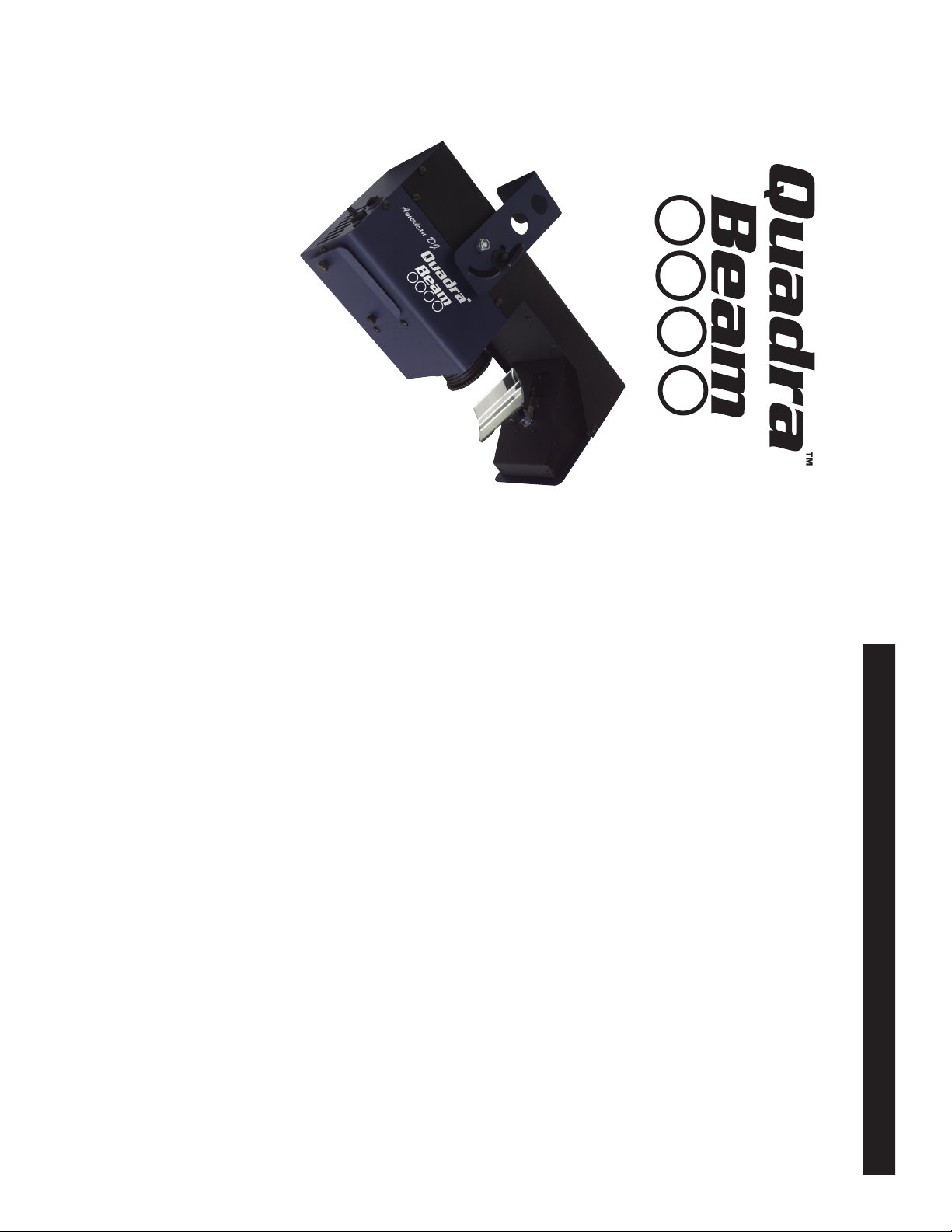
the beam output. The Quadra Beam™
gives the allusion of X / Y movement, this mirror can be adjusted by
hand. An optional MINI/C black out controller may be purchased sepa-
comes with a swivel mirror that
active piece, or in a Master/Slave configuration. The Quadra Beam™
comes with several build in programs and is best used in multiples of
four. This piece is best used with a fog or haze machine to enhance
Introduction: This unit use a single color/gobo wheel combination for
vibrant colors and extravagant gobo patterns. The Quadra Beam™ is
an intelligent fixture that can run In DMX mode, as a stand alone sound
ing customer support.
Unpacking: Thank you for purchasing the Quadra Beam™ by Ameri-
can DJ
®. Every Quadra Beam™ has been thoroughly tested and has
Quadra Beam™ General Information
been shipped in perfect operating condition. Carefully check the ship-
ping carton for damage that may have occurred during shipping. If the
carton appears to be damaged, carefully inspect your fi xture for any
damage and be sure all equipment necessary to operate the unit has
arrived intact. In the case damage has been found or parts are miss-
ing, please contact our toll free customer support number for further
instructions. Do not return this unit to your dealer without fi rst contact-
Page 2
be walked on or pinched by items placed upon or against them,
paying particular attention to cords at plugs, convenience recep-
tacles, and the point where they exit from the appliance.
• Cleaning -The fixture should be cleaned only as recommended by
the manufacturer. See page 7 for cleaning details.
• Heat -The appliance should be situated away from heat sources
such as radiators, heat registers, stoves, or other appliances (includ-
ing amplifiers) that produce heat.
• The fixture should be serviced by qualified service personnel when:
A. The power-supply cord or the plug has been damaged.
B. Objects have fallen, or liquid has been spilled into the appliance.
C. The appliance has been exposed to rain or water.
D. The appliance does not appear to operate normally or exhibits a
©American DJ Supply® - www.americandj.com - Quadra Beam™ Instruction Manual Page 3
marked change in performance.
• Power-supply cords should be routed so that they are not likely to
Quadra Beam™ Safety Precautions
• To reduce the risk of electrical shock or fi re, do not expose this unit
rain or moisture
• Do not spill water or other liquids into or on to your unit.
• Be sure that the local power outlet match that of the required voltage
for your unit.
• Do not attempt to operate this unit if the power cord has been frayed
or broken.
• Do not attempt to remove or break off the ground prong from
the electrical cord. This prong is used to reduce the risk of electrical
shock and fi re in case of an internal short.
• Disconnect from main power before making any type of connection.
• Do not remove the cover under any conditions. There are no user
serviceable parts inside.
• Never operate this unit when it’s cover is removed.
• Never plug this unit in to a dimmer pack
• Always be sure to mount this unit in an area that will allow proper
ventilation. Allow about 6” (15cm) between this device and a wall.
• Do not attempt to operate this unit, if it becomes damaged.
• This unit is intended for indoor use only, use of this product outdoors
voids all warranties.
• During long periods of non-use, disconnect the unit’s main power.
• Always mount this unit in safe and stable matter.
for a R.A. number.
©American DJ Supply® - www.americandj.com - Quadra Beam™ Instruction Manual Page 4
freight pre-paid and accompany a return authorization (R.A.) number.
If the unit is under warranty, you must provide a copy of your proof
of purchase invoice. Please contact American DJ
® customer support
The Quadra Beam™ carries a one year (365 days) limited warranty.
Please fill out the enclosed warranty card to validate your purchase.
All returned service items whether under warranty or not, must be
Quadra Beam™ Product Registration
• Easy Lamp Replacement
• Long Life ZB-JCR H5 (15v/150w) Lamp - 500 Hours
• Optional MINI/C Blackout Controller
• Unique Four-Way Mirror
• Internal Microphone
• Volume Sensitivity Knob
• Micro-Stepping Motors for Smooth Color and Gobo Transitions
• Uses Two DMX Channels
• DMX-512 Protocol Compatible
• Full Focusing
• Fan Cooled.
• 10 Gobos Plus Spot.
• Two Split Color Gobos
• Master/Slave Operation
Quadra Beam™ Features
Quadra Beam™ Halogen Lamp Warning
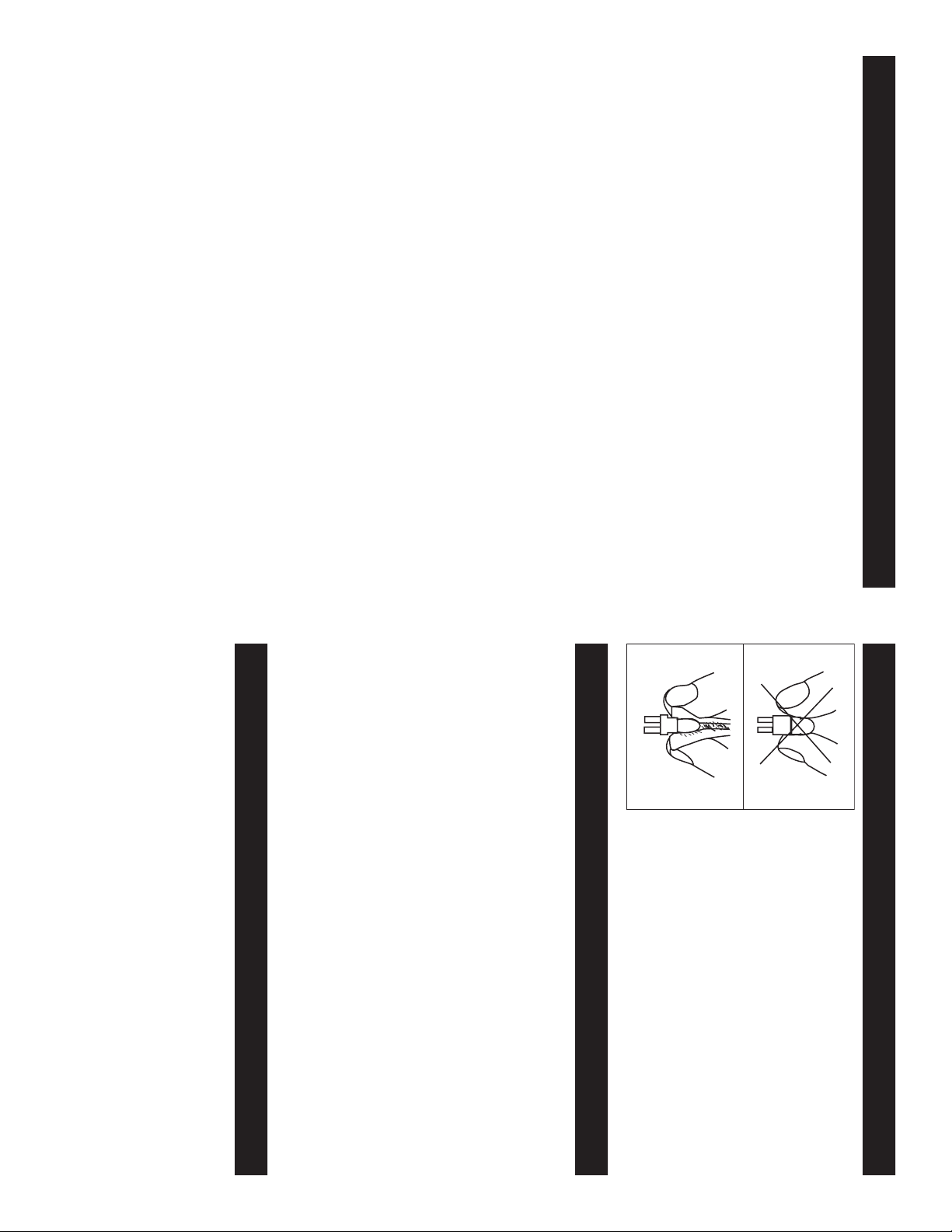
This fixture is fitted with halogen lamps which
are highly susceptible to damage if improperly
handled. Never touch the lamps with your
bare fingers as the oil from your hands will
shorten lamp life. Also, never move the fixture
until the lamps have had ample time to cool.
Remember, lamps are not covered under war-
ranty conditions.
Page 3
DMX512 OUT
3-PIN XLR
Figure 2
3 Hot
1 Ground
XLR Male Socket
2 Cold
could cause a short circuit and erratic behavior.
Notice: Be sure to follow fi gure three when making your own cables.
XLR connector on either end of the cable. Also
remember that DMX cable must be daisy chained
and can not be split.
shielded cable (This cable may be purchased at
almost all pro sound and lighting stores). Your
cables should be made with a male and female
dard 3-pin XLR connector for data input and data
output (Figure 1). If you are making your own
cables, be sure to use standard two conductor
protocol. The American DJ® Quadra Beam™ is a two channel DMX
unit. The DMX address is set on the top panel of the Quadra Beam.
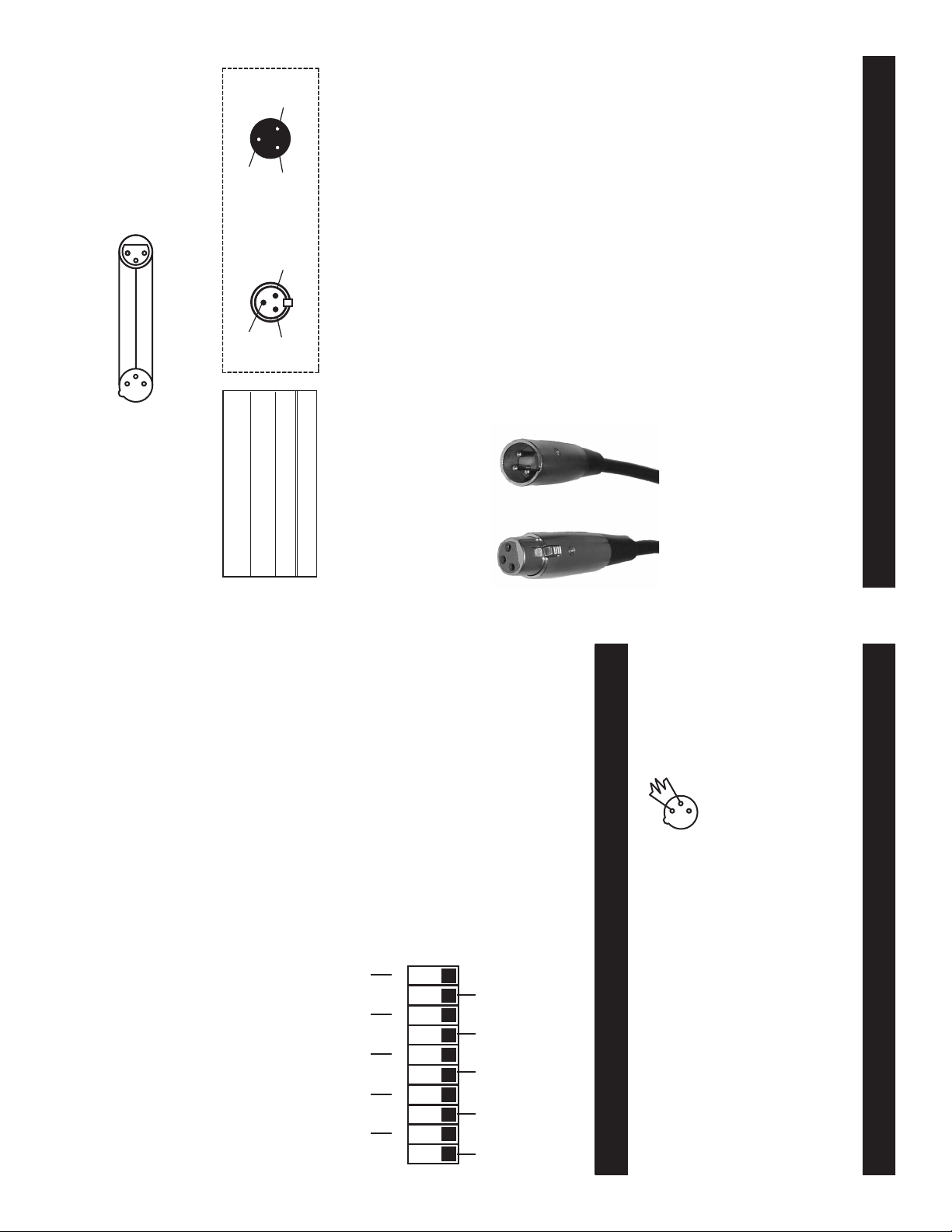
Your unit and your DMX controller require a stan-
Data Cable (DMX Cable) Requirements (For DMX and Master/
Slave Operation): The Quadra Beam can be controlled via DMX-512
you should be sure your unit voltages matches the wall outlet voltage
before attempting to operate you fi xture.
Do not use the ground lug on the XLR connector. Do not connect the
cable’s shield conductor to the ground lug or allow the shield conductor
to come in contact with the XLR’s outer casing. Grounding the shield
Power Supply: Before plugging your unit in, be sure the source volt-
age in your area matches the required voltage for your American DJ®
Quadra Beam.™ Because line voltage may vary from venue to venue,
Quadra Beam™ Set Up
1
2
3
COMMON
DMX +
DMX -
3 Hot
3
2
1
DMX512 IN
3-PIN XLR
Figure 3
Set DMX address 21: Set DMX address 201:
Dipswitches # 1 = 1 Dipswitches # 1 = 1
3 = 4 4 = 8
5 = 16 7 = 64
= 21 8 = 128
= 201
©American DJ Supply® - www.americandj.com - Quadra Beam™ Instruction Manual Page 6©American DJ Supply® - www.americandj.com - Quadra Beam™ Instruction Manual Page 5
Pin 3 = Data True (positive)
and dip switch 5 has a value of 16, the combination of the create a
DMX value of 21.
2 Cold
XLR Female Socket
1 Ground
Pin 2 = Data Compliment (negative)
Pin 1 = Ground
XLR Pin Confi guration
Dip Switch 7 address equals 64
Dip Switch 8 address equals 128
Dip Switch 9 address equals 256
Each dip switch has a preset value. A specific DMX address is set by
combining the dip switches that sum your desired value. For example:
To achieve a DMX address of 21, combine dip switches 1, 3, and 5.
Sense dip switch 1 has a value of 1, dip switch 3 has a value of 4,
Figure 1
DMX is short for Digital Multiplex. This is a universal DMX binary lan-
guage used as a form of communication between intelligent fixtures.
Each dip switch represents a binary value.
Dip Switch 1 address equals 1
Dip Switch 2 address equals 2
Dip Switch 3 address equals 4
Dip Switch 4 address equals 8
Dip Switch 5 address equals 16
Dip Switch 6 address equals 32
Quadra Beam™ DMX Addressing
behavior.
Quadra Beam™ Set Up
Special Note: Line Termination.
used, you may need to use a terminator on the last unit to avoid erratic
behavior. A terminator is a 90-120 ohm 1/4 watt resistor which is con-
nected between pins 2 and 3 of a male XLR connector (DATA + and
DATA -). This unit is inserted in the female XLR connector of the last
unit in your daisy chain to terminate the line. Using a cable terminator
(ADJ part number ZDMX/T) will decrease the possibilities of erratic
3
2
1
Termination reduces signal errors and
avoids signal transmission problems
and interference. It is always advisable
to connect a DMX terminal, (Resistance
120 Ohm 1/4 W) between PIN 2 (DMX-)
and PIN 3 (DMX +) of the last fixture.
ON
When longer runs of cable are
198765432 10
DMX CHANNEL
Figure 4
12828 32
256651641
SP
Page 4
©American DJ Supply® - www.americandj.com - Quadra Beam™ Instruction Manual Page 7
To next DMX unit or terminate.
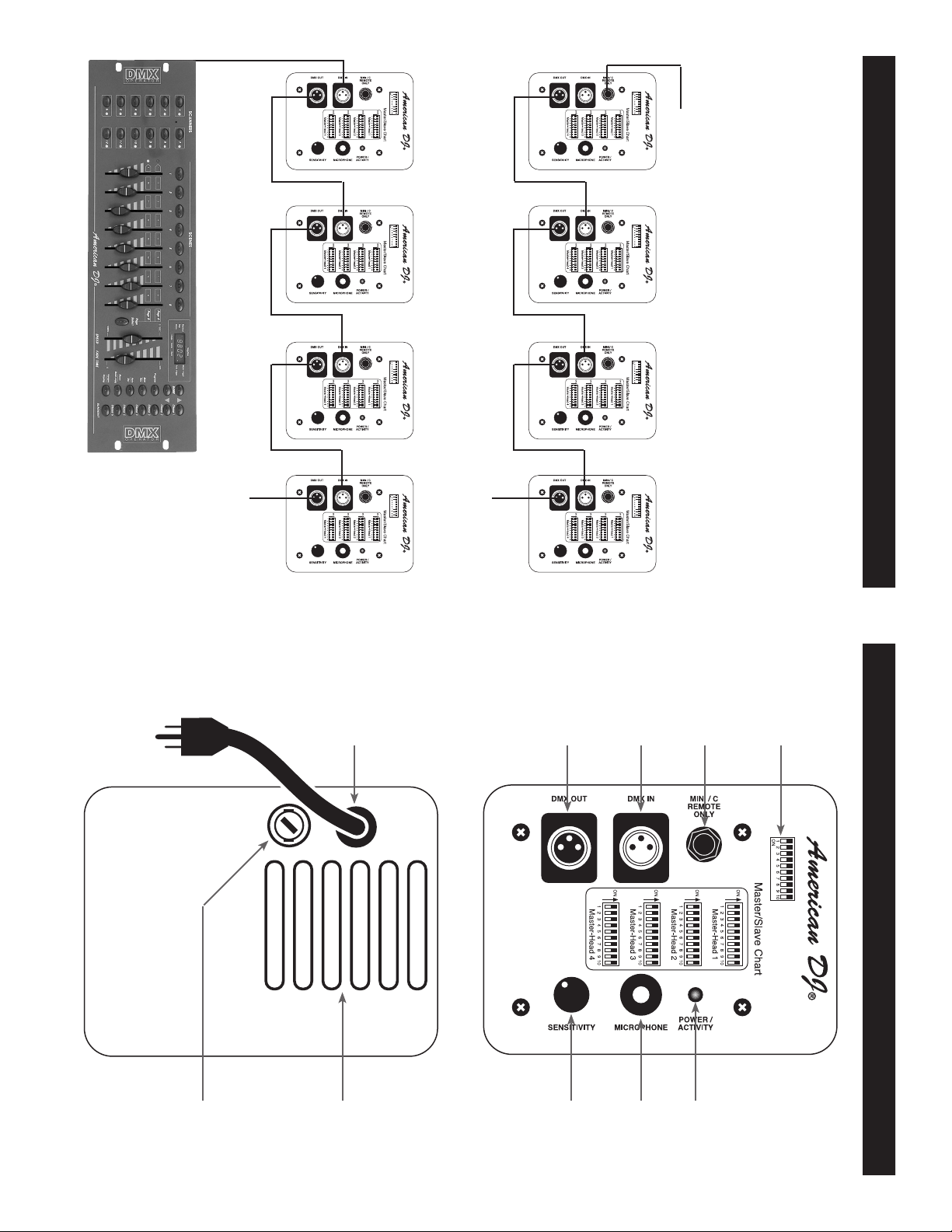
DMX Linking:
DMX function allows independent control of each fi xture.
To next Quadra Beam if applicable
Master/Slave Linking:
For a more dramatic effect, link several Quadra Beams together.
Optional MINI/C blackout controller
Unit” or a “Slave Unit.” Link the units together using standard DMX
cable.
Linking: Your fi xture comes with built-in programs. These programs
are designed to work with up to 16 units when daisy-chained together in
a master-slave confi guration. Any unit can function as either a “Master
Quadra Beam™ Linking
©American DJ Supply® - www.americandj.com - Quadra Beam™ Instruction Manual Page 8
8
BOTTOM
TOP
4
3
2
1
Quadra Beam™ Controls and Functions
9
10
5
6
7
Page 5

10. Cooling Vents - These vents are used to allow proper cooling.
Keep the vents clean. Never block the vents, improper cooling may
result in premature lamp failure.
9. Fuse Holder - This housing stores the 3 amp GMA protective
fuse. Always replace with the exact same type fuse, unless other
wise instructed, by an authorized American DJ
® service technician.
7. Power Indicator - This LED will fl ash when it receives either an
6. Microphone - This microphone receives external low frequencies
to trigger the unit in Sound-Active and Master/Slave mode..
the counter clockwise direction will decrease the fi xture’s sensitivity
to sound.
5. Audio Sensitivity Knob - This adjust audio sensitivity of the
internal microphone (5). Turning the sensitivity knob in the clockwise
direction will increase the sensitivity to sound. Turning the knob in
or Master/Slave mode terminate this jack if it is the last unit in the
chain. See “Terminator” on page 7.
4. XLR Output Jack - This jack is used to transmit the incoming
DMX signal to another DMX fi xture, or transmit a Master/Slave signal
to the nest Quadra Beam™ in the chain. For best results in DMX
audio or DMX signal.
8. Power Cord - Connect only to a matching power outlet. Never use
this fi xture is the ground prong has been removed or broken off.
signal or Master/Slave signal.
Quadra Beam™ Controls and Functions
1. Dip Switches - These switches serve two functions. In master
slave mode these switches are used to assign a specifi c head
address. In DMX mode these switches are used to assign a DMX
address to the unit. In DMX mode each switch corresponds to a
specifi c value based on binary code. See page 7 for a detailed
explanation of DMX binary code.
2. MINI/C Controller Jack - This jack is for use with the optional
MINI/C Blackout controller only. Do not attempt to connect an audio
signal this jack, this will damage the PC board and void your manfac
tures warranty!
3. XLR Input Jack - This jack is used to accept an incoming DMX
©American DJ Supply® - www.americandj.com - Quadra Beam™ Instruction Manual Page 10©American DJ Supply® - www.americandj.com - Quadra Beam™ Instruction Manual Page 9
function for blackout.
Stand-Alone Operation (Sound Active): This function allows a
single unit to run to the beat of the music. Only use this function when
running a single unit, or when running several units as individuals.
1. To activate the Sound-Active mode, set dip switch #10, to the ON
position (See “Master Unit” on the DIP SWITCH chart on page 14).
2. The unit will now react to the low frequencies of music via the inter-
nal microphone.
3. Adjust the audio sensitivity knob on the top of the unit to make the
unit more or less sensitive to sound. Turning the sensitivity knob in
the clockwise direction will increase the sensitivity, turning the knob
in the counter-clockwise direction will decrease the fi xture’s sensi-
tivity to sound.
4. The optional MINI/C Blackout Controller may be used with this
the last fixture.
Quadra Beam™ Operation
Universal DMX Control: This function allows you to use a universal
DMX 512 controller as the American DJ® DMX Operator™ or Show
Designer.™ to control mirror movement and the color/gobo wheel. The
use of a DMX controller will allow you to customize the use of fixtures
allowing you to control the rotation direction as well as the rotation
speed. Operating through a DMX controller allows the freedom to
create unique programs tailored to one’s individual needs.
1. The Quadra Beam™ uses two DMX channels. Channel one con-
trols the color/gobo wheel and channel two controls mirror move-
ment, please see page 13 for detailed description of the DMX
traits.
2. To control your fixture in DMX mode, follow the set-up procedures
on pages 5 - 7 as well as the set-up specifications that are included
with your DMX controller.
3. Use the controller’s faders to control the various DMX fixture traits.
4. This will allow you to create your own programs.
5. When using a DMX controller and setting up for DMX operation
follow the dip switch settings on page 14.
6. For help operating in DMX operation consult the manual included
with your DMX controller.
7. For longer cable runs (more than a 100 feet) use a terminator on
Page 6
unless otherwise specified by an authorized American DJ® technician.
fuse and discard it. Replace the fuse with the same type. Insert the
©American DJ Supply® - www.americandj.com - Quadra Beam™ Instruction Manual Page 11 ©American DJ Supply® - www.americandj.com - Quadra Beam™ Instruction Manual Page 12
unit and will void your manufactures warranty.
Warning: If, after replacing the lamp or fuse either one continues
to blow, STOP using the unit. Contact customer support for further
instructions, you may have to return the unit for servicing. Continuing
to use the unit may cause serious damage.
Fuse Replacement: Disconnect the unit’s main power supply. Insert
a standard flat head screw driver in to the fuse holder housing. Turn
the screwdriver in counter-clockwise direction to remove the fuse
holder. Remove the fuse holder to expose the fuse. Remove the old
Replace with anything other than the specified part can damage your
Caution: Always replace with the exact same type lamp and fuse,
Quadra Beam™ Fuse & Lamp Replacement
there is no sound present.
react to sound.
vate! The units will blackout in this mode to conserve bulb life when
Note: Stand-Alone and Master-Slave operation require sound to acti-
3. The optional MINI/C Blackout Controller may be used with this
XLR connector only. For longer cable runs we suggest a terminator
at the last fixture.
2. Follow the chart on page 13 for proper unit dip switch settings.
the Male XLR connector is the input and the Female XLR connector
is the output. The fi rst unit in the chain (master) will use the female
XLR connector only - The last unit in the chain will use the male
units programs. Any unit can act as a Master or as a Slave.
1. Using standard XLR microphone cables, daisy chain your units
together via the XLR connector on the rear of the units. Remember
allow you to link up to 4 units together and operate without a controller.
The units will be sound activated. In Master-Slave operation one unit
will act as the controlling unit and the others will react to the controlling
Master-Slave Operation (Sound Active): This function will
Quadra Beam™ Operation
function for blackout.
4. After all the units settings have been set and are plugged in, adjust
the sensitivity knob on the rear of the master unit to make them
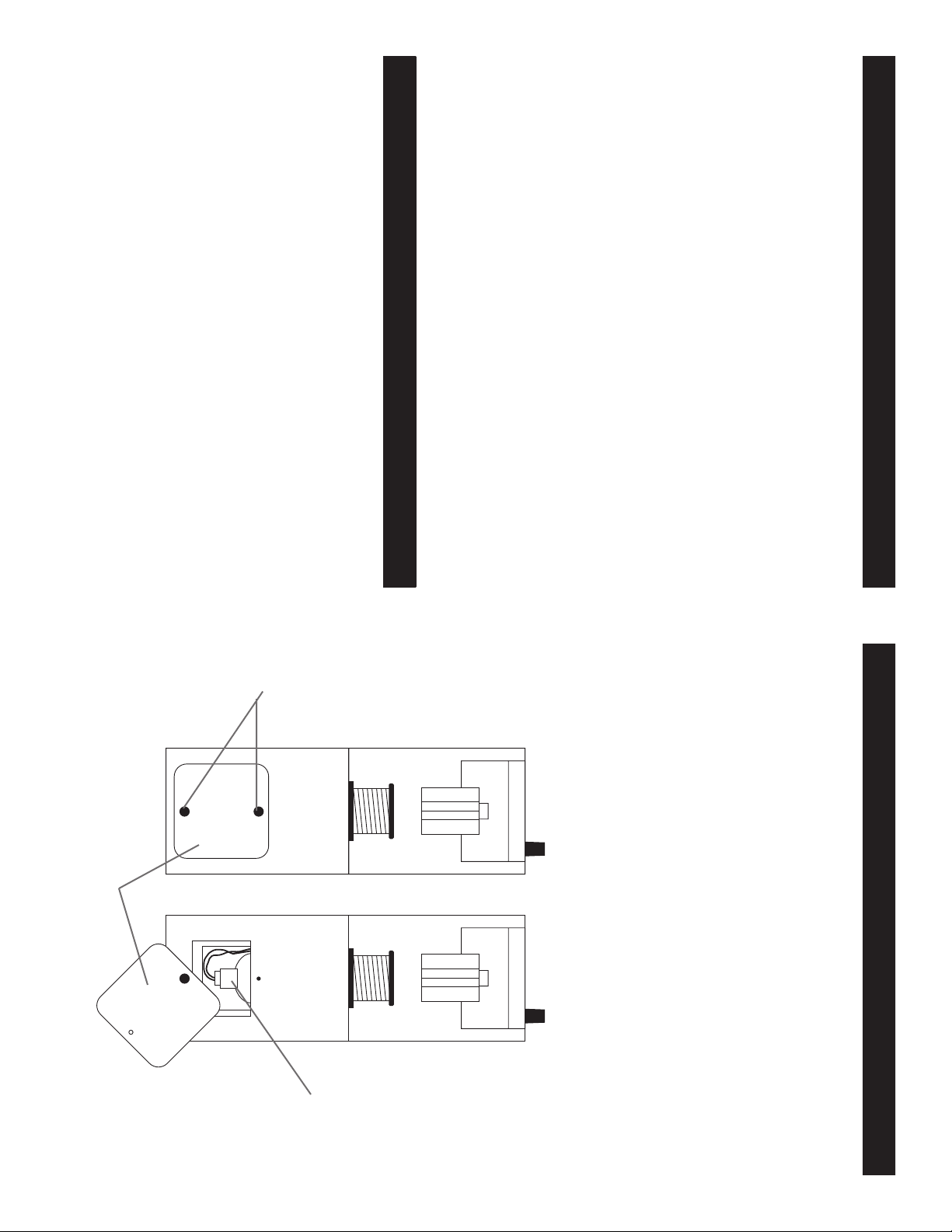
Lamp Cover
Thumb screws
Lamp Socket
Assembly
Lamp Replacement: Caution! Never attempt to change the lamp
while the fixture is plugged in. Always disconnect the main power and
allow the unit ample time to cool before attempting to replace the
lamp. Lamp replacement has been made simple by incorporating the
use of a flip-up front cover that is retained by thumb screws.
1. Be sure to follow the proper handling procedures that deal
with halogen lamps. Never touch the new lamp with your bare
fingers.
2. Remove the thumb screws on the front of the unit that hold the
lamp socket assembly cover in place.
3. Carefully remove the old lamp and discard it in the trash.
4. Replace the lamp with an exact match and reassemble.
fuse holder back into it’s housing and turn it in clockwise direction to
lock the holder in place.
Quadra Beam™ Fuse & Lamp Replacement
Page 7
No light output from the unit;
1. Be sure you have connected your unit into a standard 120V wall
outlet.
2. Be sure the external fuse has not blown. The fuse is located on the
bottom panel of the unit.
3. Remove the lamp cover and be sure the lamp is seated in its
socket properly. Occasionally lamps become loose during shipping
be sure the lamp is push in to its socket all the way.
4. Be sure the fuse holder is completely and properly seated.
Unit does not respond to sound;
1. Low frequencies (bass) should cause the unit to react to sound.
Ta ppin g on t he microphone, quiet or high pitched sounds may not
activate the unit.
2. Be sure the SENSITIVITY KNOB (5) is not set to the minimum
position
©American DJ Supply® - www.americandj.com - Quadra Beam™ Instruction Manual Page 13
Troubl e Sh ooting:
Listed below are a few common problems that you may encounter,
with solutions.
cloth every 20 days.
4. Clean the internal optics with glass cleaner and a soft cloth every
30-60 days.
5. Always be sure to dry all parts completely before plugging the unit
back in.
Quadra Beam™ Trouble Shooting
3. Clean the external optics and mirror with glass cleaner and a soft
Fixture Cleaning:
Quadra Beam™ Cleaning
Due to fog residue, smoke, and dust cleaning the internal and external
optical lenses and mirror should be carried out periodically to optimize
light output. Cleaning frequency depends on the environment in which
the fixture operates (I.e. smoke, fog residue, dust, dew). In heavy club
use we recommend cleaning on a monthly basis. Periodic cleaning will
ensure longevity, and crisp output.
1. Use normal glass cleaner and a soft cloth to wipe down the outside
casing.
2. Use a brush to wipe down the cooling vents and fan grill.
©American DJ Supply® - www.americandj.com - Quadra Beam™ Instruction Manual Page 14
ON
198765432 10
Head 3
198765432 10
Head 4
19876543210
Master - Head 1
ON
198765432 10
Head 2
settings should only be used once.
ON
ON
Quadra Beam™ Master/Slave Settings
This chart details the Master/Slave dip switch setting for Master/Slave
configuration. Use this configuration when you will be using two or
more fixtures in a Master/Slave configuration. The Master - Head 1
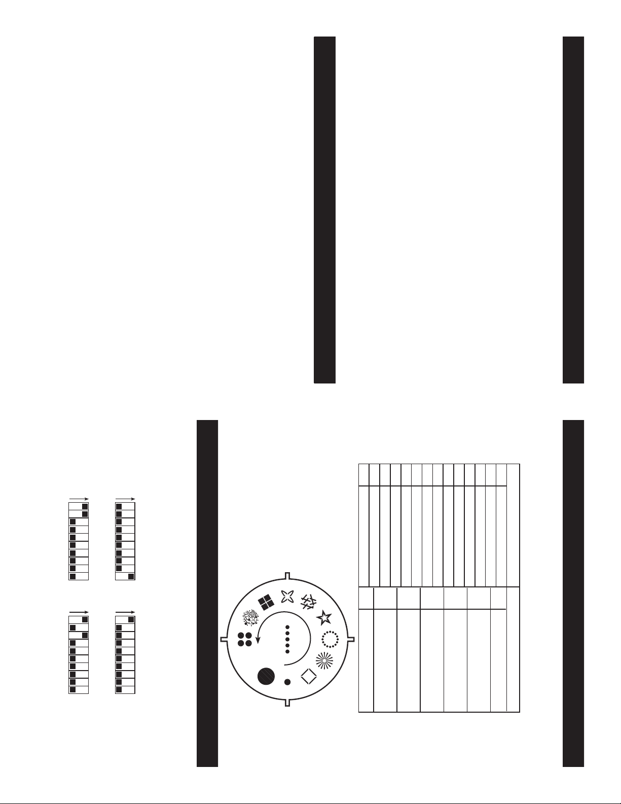
GOBO 1
This chart detail the internal
gobo wheel. Gobo one is the
large spot. The arrow indi-
cates the wheeel rotaion.
01-17
00
WHITE/LARGE SPOT
BLACKOUT
00
90˚ MIRROR POSITION
120-136
103-119
86-102
69-85
52-68
35-51
18-34
WHITE/SMALL SPOT
RED/GOBO 3
BLUE/GOBO 4
GREEN/GOBO 5
YELLOW/GOBO 6
LT B LUE/GOBO 7
BLUE-YELLOW/GOBO 8
200-210
SLOW CW ROTATION
211-221
MD SLOW CW ROTATION
01-199
CW STEP MOVEMENT
171-188
154-170
137-153
RED-GREEN/GOBO 9
222-233
MEDIUM CW ROTATION
205-254
Channel 1 - COLOR/GOBO
255
PINK/GOBO 10
U.V./GOBO 11
CONTINOUS SCROLL
SOUND ACTIVE MODE
234-244
FAST CW ROTATION
Channel 2 - MIRROR ROTATION
255
SOUND ACTIVE MODE
This chart below details the DMX traits of the fixture. The individual
trait can only be accessed an universal DMX controller. Note: The
Quadra Beam™ has a special DMX function
Quadra Beam™ DMX Traits
Page 8
©American DJ Supply® - www.americandj.com - Quadra Beam™ Instruction Manual Page 15
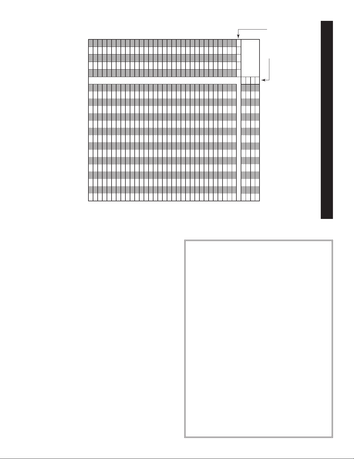
The center numbers of this chart (1-511) represent a DMX address. The "X"'s
and "O"'s along the top and side of the chart represent dip switch poistion ("X"
for off and "O" for on). Find your desired DMX address from the center chart.
Identify the position for dip switches 1-5 from the chart on the left and dip
switches 6-9 from the chart on the top. Adjust the dip switches on your fixture to
match the position settings of the chart. For fixtures with 10 dip switches; dip
switch 10 is reserved for special functions.
OOOOO
X OOOO
OXOOO
XXOOO
28 60 92 124 156 188 220 252 284 316 348 380 412 444 476 508
30 62 94 126 158 190 222 254 286 318 350 382 414 446 478 510
31 63 95 127 159 191 223 255 287 319 351 383 415 447 479 51
29 61 93 125 157 189 221 2 53 285 317 349 381 413 445 477 509
OOXOO
XOXOO
O XXOO
25 57 89 121 153 185 217 249 281 313 345 377 409 441 473 505
27 59 91 123 155 187 219 251 283 315 347 379 411 443 475 507
26 58 90 122 154 186 218 2 50 282 314 346 378 410 442 474 506
XXXOO
24 56 88 120 152 184 216 248 280 312 344 376 408 440 472 504
Dip Switch Position
X OOX O
22 54 86 118 150 182 214 246 278 310 342 374 406 438 470 502
OXOX O
21 53 85 117 149 181 213 245 277 309 341 373 405 437 469 501
XXOXO
20 52 84 116 148 180 212 244 276 308 340 372 404 436 4 68 500
OOXXO
19 51 83 115 147 179 211 243 275 307 339 371 403 435 4 67 499
OOOXO
23 55 87 119 151 183 215 247 279 311 343 375 407 439 4 71 503
XOXXO
18 50 82 114 146 178 210 242 274 306 338 370 402 434 466 498
X OOOX
O XXXO
XXXXO
OOOOX
OXOOX
13 45 77 109 141 173 205 237 269 301 333 365 397 429 461 493
15 47 79 111 143 175 207 239 271 303 335 36 7 399 431 463 495
16 48 80 112 144 176 208 240 272 304 336 368 400 432 464 496
14 46 78 110 142 174 206 238 270 302 334 366 398 430 4 62 494
17 49 81 113 145 177 209 241 273 305 337 369 401 433 4 65 497
XOXOX
O XXOX
XXOOX
OOXOX
10 42 74 106 138 170 202 234 266 298 330 362 394 426 458 490
12 44 76 108 140 172 204 236 268 300 332 364 396 428 460 492
11 4 3 75 107 139 171 20 3 235 267 299 331 363 395 427 459 491
94173105137 169 20 1 233 265 297 329 361 39 3 425 457 489
XXXOX
84072104 136 168 200 232 264 296 328 360 392 424 456 488
OOOXX
73971103135 167 19 9 231 263 295 327 359 39 1 423 455 487
X OOX X
63870102134 166 19 8 230 262 294 326 358 39 0 422 454 486
XXOXX
OOXXX
OXOX X
43668100132 164 19 6 228 260 292 324 356 38 8 420 452 484
3356799131163195227 259 291323355 387 419 451 483
53769101 133 165 197 229 261 293 325 357 389 421 453 485
#1 #2 #3 #4 #5
O XXXX
XOXXX
XXXX
O = ON
X
#6
1336597129161193225 257 289321353 385 417 449 481
2346698130 162 19 4 226 258 290 322 354 38 6 418 450 482
36496128160192224 256 288320352 384 416 448 480
DIP SWITCHES
DMX DIP Switch Settings
X = OFF
#9
#8
#7
This chart list the DMX dip switch setting for DMX address 1 through
511. Follow the instructions below to configure fixture dip switches with
your desired DMX address.
Quadra Beam™ DMX Dip Switch Chart
DMX Address Quick Reference Chart
DMX Address
1
DMX Address
American DJ Supply Group of Companies World Headquarters:
prior written notice.
Web: www.americandj.com E-mail: [email protected]
4295 Charter Street Los Angeles, CA 90058 USA
O
XOXXOOOXOXXOXOX
Please Note: Specifi cations and improvements in the design
of this unit and this manual are subject to change without any
Sound Active: Yes
Working Position: Any Safe, Secure Position
Warranty: 1 Year (365 days)
DMX: 2 Channels
Duty Cycle: 15 min on/off
Weight: 12 Lbs.
Fuse: 3 Amp GMA
Dip Switch Position
OOOOOXOOOXXXXXXX
OOOOOOOOXXXXXX XX
OXOXOOXXOOXX XXOO
Gobos: 10, plus spot
2 white spots
Colors 7 solid color gobos,
2 split color gobos,
with yoke extended
Technical Specifications:
Model: Quadra Beam
Lamps: ZB-JCR H5 15v/150w
Voltage: 120v/60Hz
Dimensions: 14.25”(H) x 6.75”(W) x 9.75”(D)
Tel: 323-582-2650 Fax: 323-582-2610
©American DJ Supply
 Loading...