

Page 1
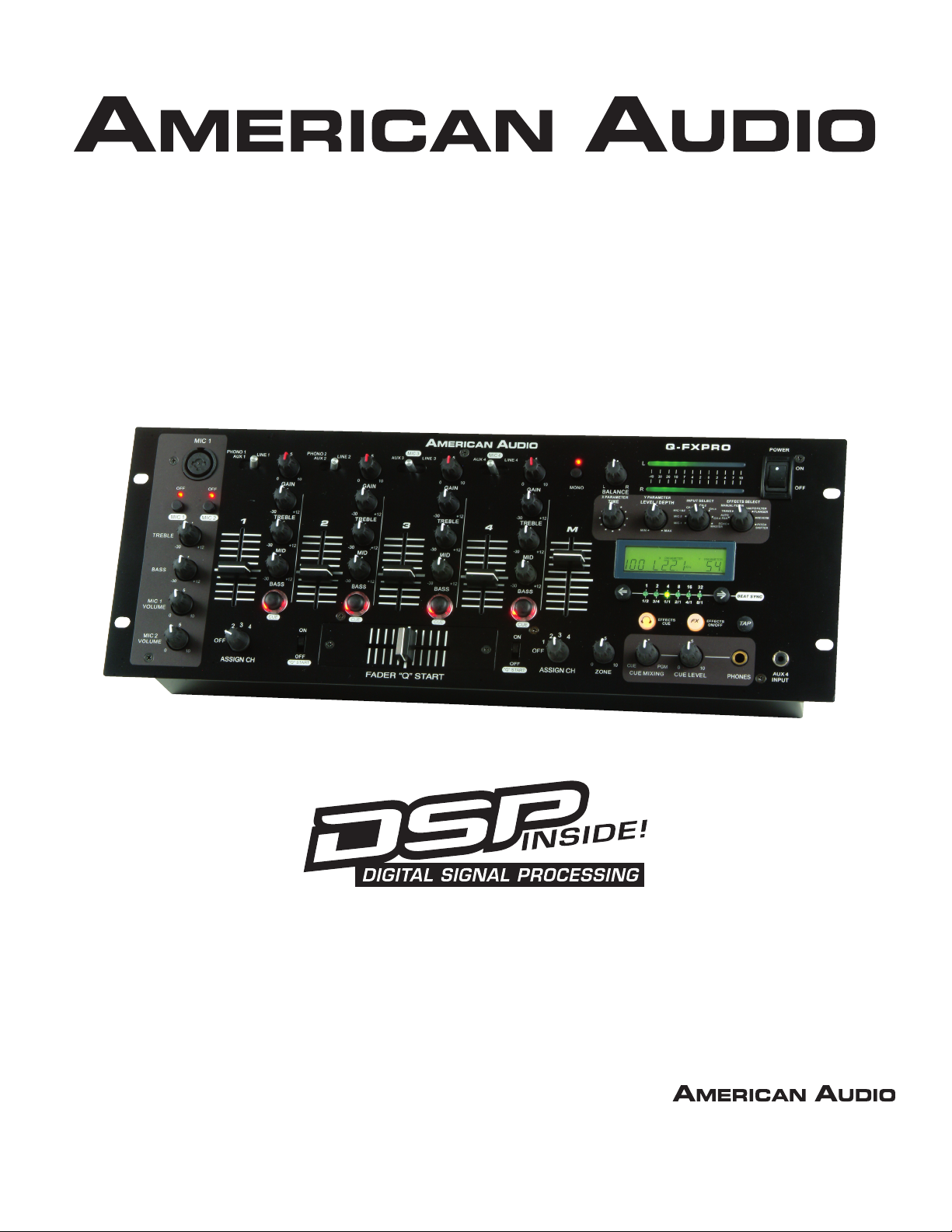
Q-FXPRO
12/06
User Guide
and Reference Manual
4295 Charter Street
Los Angeles Ca. 90058
www.AmericanAudio.us
Page 2

Q-FXPRO CONTENTS
MAIN FEATURES....................................................................................................................................2
ELECTRICAL PRECAUTIONS................................................................................................................3
SAFETY PRECAUTIONS........................................................................................................................5
INTRODUCTION....................................................................................................................................6
SET-UP PRECAUTIONS.........................................................................................................................6
UNPACKING.........................................................................................................................................7
QUICK START........................................................................................................................................7
CONTROLS AND FUNCTIONS
FRONT PANEL............................................................................................................................8
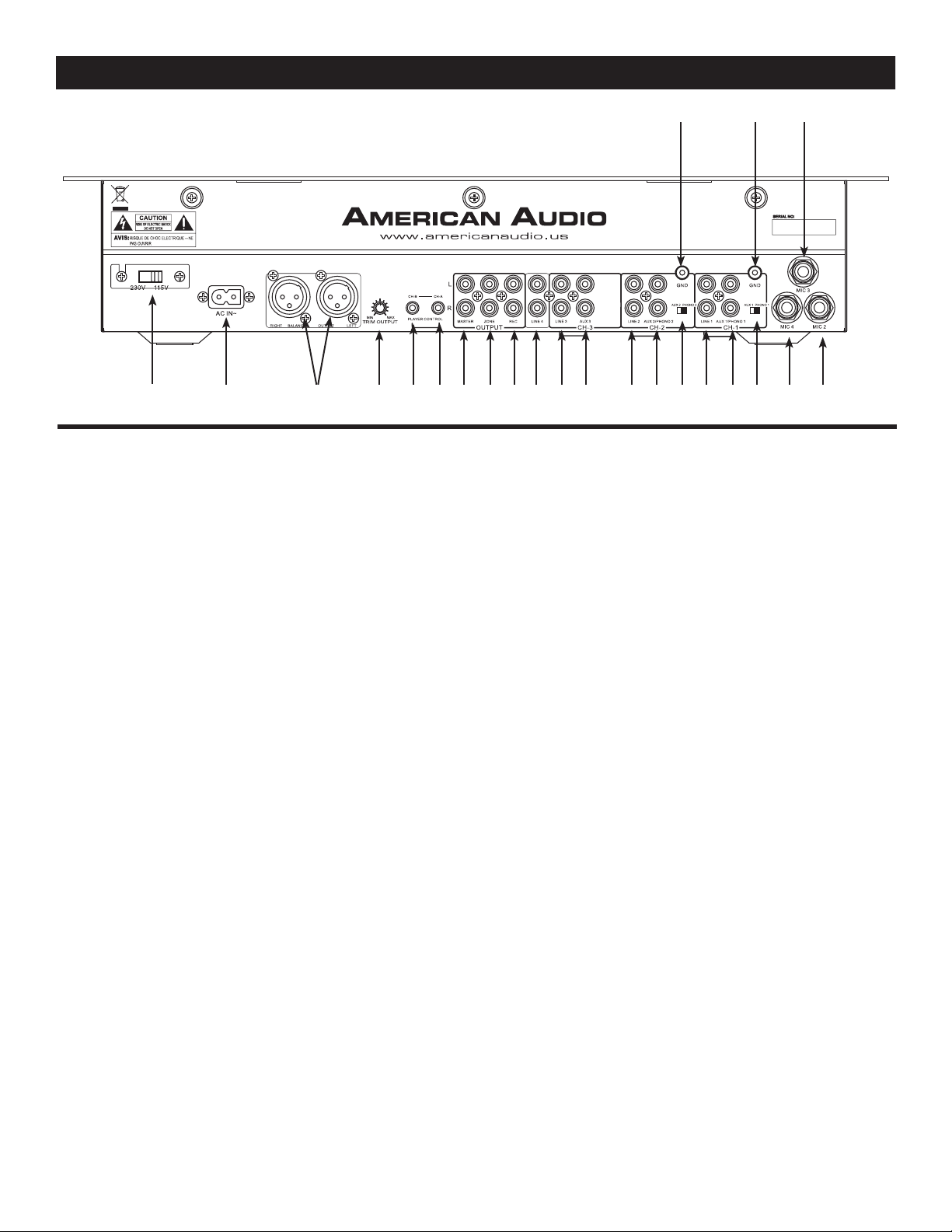
REAR PANEL............................................................................................................................12
LCD SCREEN/DSP EFFECTS...................................................................................................15
TYPICAL MIXER SET-UP......................................................................................................................16
CLEANING......................................................................................................................18
CROSSFADER REPLACEMENT...........................................................................................................18
TROUBLESHOOTING......................................................................................................................19
WARRANTY.........................................................................................................................................20
SPECIFICATIONS.....................................................................................................................21
Q-FXPRO MAIN FEATURES
• Feather Fader Plus for Q-Start Control
• 2 Phono, 4 Line, 4 Auxiliaries & 4 Mic Inputs
• Balanced outputs
• High quality Feather Fader™ for smooth, clean
cross fades (replaceable)
• Bass, Mid, and Treble for each channel
• Zone Output
• Mono/Stereo Switch on Master
• High level headphone output
• Cue mixing
• Split cue for headphones
• Turntable ground connectors located on the rear
panel
• Adjustable Crossfader Curve
• On/Off switch for channel assign
• Gain control for each channel
• Rear inset “L” shape case design
• 115v/230v selectable
• Q-Start Compatible (for use with American
Audio CD Players with Fader “Q” Start)
• Master Level Indicator
• Balanced XLR Output
• DSP Effects - Trans, Pan, Filter, Auto Filter,
Pitch Shift, Flanger, Reverb, and Echo
• Digital BPM Display
• Master Output Trim Control
©American Audio® - www.americanaudio.us - Q-FXPRO Instruction Manual Page 2
Page 3
Q-FXPRO ELECTRICAL SAFETY PRECAUTIONS
WARNING: TO PREVENT FIRE OR ELECTRIC
SHOCK HAZARD, DO NOT EXPOSE THIS
UNIT TO RAIN, LIQUIDS, OR MOISTURE
CAUTION: TO PREVENT ELECTRIC SHOCK
DO NOT USE THIS (POLARIZED) PLUG
WITH AN EXTENSION CORD, RECEPTACLE,
OR OTHER TYPE OF ELECTRICAL OUTLET
UNLESS THE WIDE BLADES CAN BE
CAREFULLY INSERTED INTO A MATCHING
WIDE SLOT.
ATTENTION: POUR PREVENIR LES CHOCS
ELECTRIQUES NE PAS UTILISER CETTE
FICHE POLARISEE AVEC UN PROLONGATEUR, UNE PRISE DE COURANT OU
UNE AUTRE SORTIE DE COURANT, SAUF
SI LES LAMES PEUVENT ETRE INSEREES A
FOND SANS EN LAISSER AUCUNE PARTIE A
DECOUVERT.
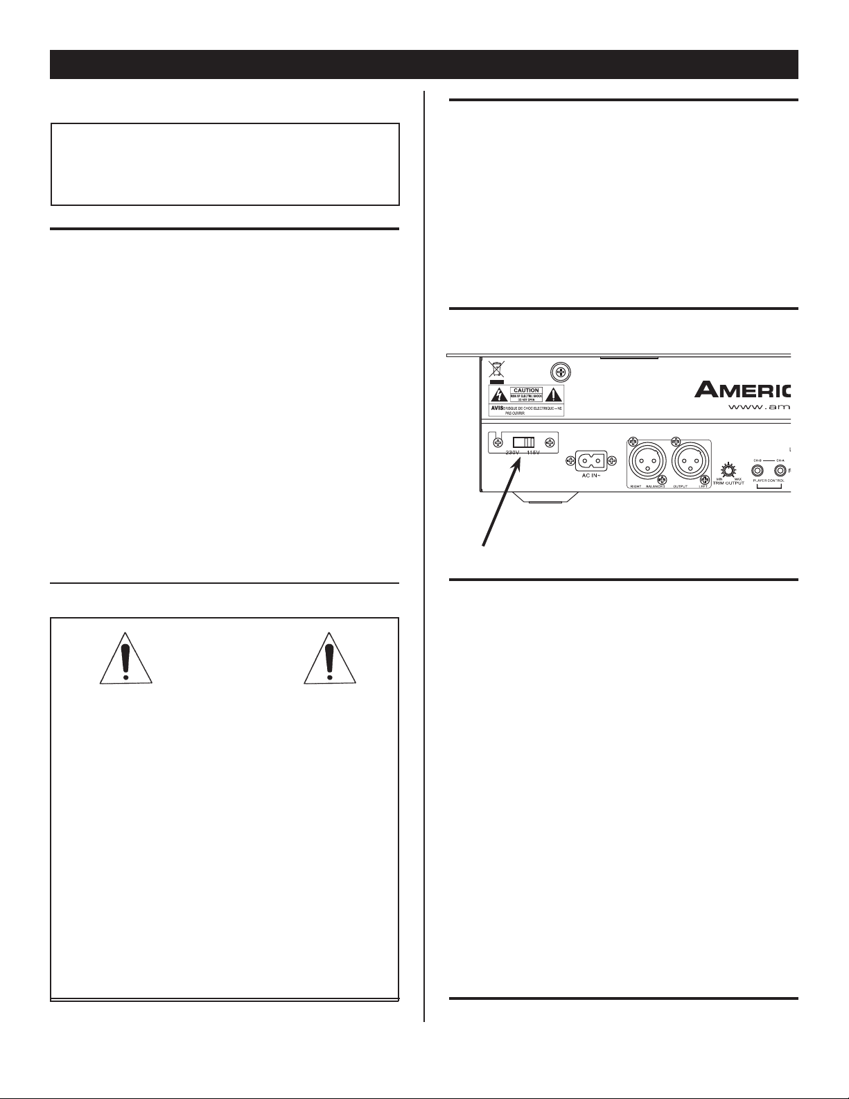
LINE VOLTAGE SELECTION
• The desired voltage may be set with the
VOLTAGE SELECTOR switch on the rear
panel (using a flat head screw driver).
• Do not force the VOLTAGE SELECTOR
switch as this may cause damage
• If the VOLTAGE SELECTOR switch does
not move smoothly, please contact a quali fied service technician.
VOLTAGE SELECTOR SWITCH
NOTE: This product satisfies FCC
regulations when shielded cables
and connectors are used to con
nect the unit to other equipment.
To prevent electromagnetic inter
ference with electrical appliances
such as radios and televisions, use
shielded cables and connectors
for connections.
The serial and model number for this unit is
located on the rear panel. Please write down
the numbers here and retain for future refer
ence.
Model No._____________________________
Serial No._____________________________
Purchase Notes:
Date of Purchase_______________________
Dealer Name__________________________
Dealer Address_________________________
_____________________________________
_____________________________________
Dealer Phone__________________________
-
©American Audio® - www.americanaudio.us - Q-FXPRO Instruction Manual Page 3
Page 4
Q-FXPRO ELECTRICAL SAFETY PRECAUTIONS
ELECTRICAL PRECAUTIONS
CAUTION
RISK OF ELECTRIC SHOCK
DO NOT OPEN
The lightning flash with arrowhead symbol, within an
equilateral triangle, is intended to alert the user to the
presence of uninsulated "dangerous voltage" within the
product's enclosure that may be of sufficient magnitude
to constitute a risk of electric shock to persons.
CA UT IO N: T O RE DUC E TH E RI S K OF ELE CT RIC
SHOCK, D O NOT REMOVE THE CO VER (OR BACK).
T H E R E A RE NO US E R S E RV I CE A BL E PA RT S
INS ID E R EF ER SERVI CE TO YO UR AUTHO RI ZED
AMERICAN A UDIO® SERVICE TECHNICIAN.
The exclam ation point within an equilate ral triangle is
intended to alert the user to the presence of important
operatin g and maintenance (servicing) instru ctions in
the litera ture accompanying the applia nce.
IMPORTANT SAFETY INSTRUCTIONS
READ INSTRUCTIONS — All the safety and operating
instructions should be read before the product is
operated.
RETAIN INSTRUCTIONS — The safety and operatin
instructions should be retained for future reference.
HEED WARNING
in the operating instructions should be adhered to.
FOLLOW INSTRUCTIONS — All operating and use
instructions should be followed.
CLEANING
a polishing cloth or a soft dry cloth. Never clean with
furniture wax, benzine, insecticides or other volatile
liquids since they may corrode the cabinet
ATTACH MENTS — Do n ot use atta chmen ts not
recommended by the product manufacturer as they
may cause hazards.
WATER AND MOISTURE
near
bowl, kitchen sink, or laundry tub; in
or near a swimming pool; and the like.
ACCESSORIES
unstable cart, stand, tripod, bracket, or table. Th
product may
adult, and serious damage to the product. Use only
wit h a c art, st and , tr ipo d, brac ket , o r ta ble
recommended by the manufacturer, or sold
the product. Any mounting of the product shoul
follow the manufacturer’s instructions, and should
use
manufacturer
CART — A product and cart combination should be
moved
uneven surfaces may cause the product and car
combination to overturn
VENTILATION
provided for ve ntilation and to e nsure rel iabl
operation of the product and
overheating, and these openings must not be
blocked or covered. The openings should never be
blocked by placing the product on
or other
placed
rack unless proper ventilation
manufacturer’s instructions have been adhered
POWER SOURCES
only from the type of power source indicated on
marking label.
power supply
dealer or local power company.
LOCATIO
stable location.
NONUSE PERIOD
should be unplugged from the
used for a long period of time.
S — All warnings on the product and
— The product should be cleaned only with
.
water — for example, near a bathtub, wash
a mounting accessory recommended by the
with care. Quick stops, excessive force, and
— Slots and openings in the cabinet are
similar surface. This product should not be
in a built-in installation such as a bookcase or
N – The appliance should be installed in a
— Do not use this product
a wet basement;
— Do not place this product on an
fall, causing serious injury to a child or
with
.
.
to protect it from
a bed, sofa, rug,
is provided or the
— This product should be operated
If you are not sure of the type of
to your home, consult your product
S – The power cord of the appliance
outlet when left un-
the
GROUNDING OR POLARIZATION
• If this product is equipped with a polarized alternating
g
e
d
t
e
to.
current line plug
the other),
is a safety feature. If you are unable to insert the plug
fully into the outlet, try reversing the plug. If the plug
should
replace your obsolete outlet. Do not defeat the
safety purpose of the polarized plug.
• If th is product is equipped wit h a th ree-w ire
grounding type plug,
pin,
it will only fit into a grounding type power outlet.
This
is a safety feature. If you are unable to insert the
plug
replace your obsolete outlet. Do not defeat the
safety purpose of the grounding type plug.
POWER-CORD PROTECTION
should be routed so that they are not likely
walked on or pinched by
against them, paying particular attention
plugs, convenience receptacles, and the point where
they exit from the product
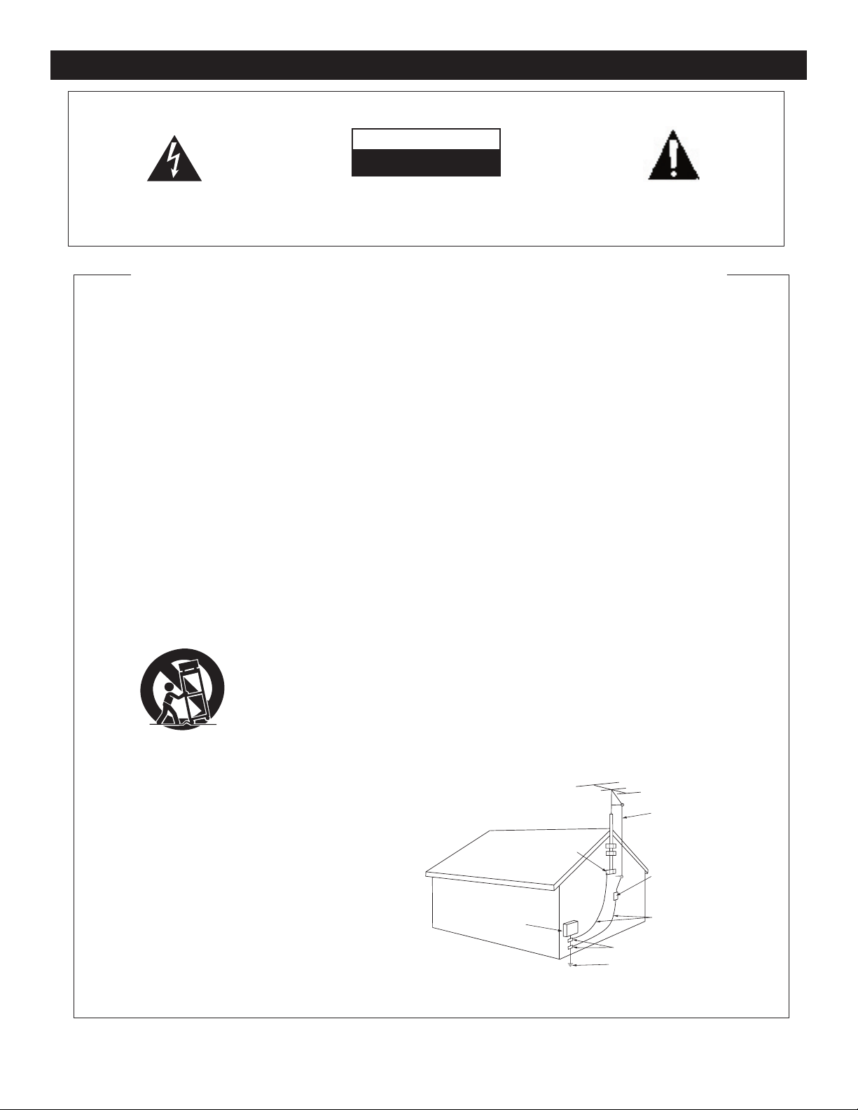
OUTDOOR ANTENNA GROUNDING
antenna or cable system is connected to the product
be sure the antenna or cable system
as to provide some protection against voltage surges
and built-up static charges. Article 810 of the National
Electrical Code, ANSI/NFPA 70, provides informatio
with regard to proper grounding of the mast and
supporting structure, grounding of the lead-in wire
to an antenna discharge unit, size of grounding
conductors, location of antenna-discharge unit,
co nn ecti on t o groun di ng e le ctro des, an d
requirements for the grounding electrode. See Figure
A.
LIGHTNING
during
and unused for long periods of time, unplug it from
the
wall outlet and disconnect the antenna or cable
system. This
due to lightning and power-line surges.
POWER LINES
not be located
or other electric light or power circuits, or where it
fall into such power lines or circuits. When
can
installing an outside antenna system, extreme car
should be taken
lines or circuits as contact with them might be
OVERLOADING — Do not overload wal l outlets,
extension cords, or integral convenience receptacles
as this can result in a risk of fire or electric shock.
(a plug having one blade wider than
it will fit into the outlet only one way. This
still fail to fit, contact your electrician to
a plug having a third (grounding)
into the outlet, contact your electrician to
- Power-supply cords
items placed upon or
.
— For added protection for this product
a lightning storm, or when it is left unattended
will prevent damage to the product
— An outside antenna system should
in the vicinity of overhead power lines
to keep from touching such power
to be
to cords at
— If an outside
is grounded so
fatal.
ELECTRI
SERVICE
EQUIPMENT
Fig.
A
,
n
e
C
OBJECT AND LIQUID ENTRY
any kind
into this product through openings as they
may touch dangerous voltage points or short-out
parts that could result
Never spill liquid of any kind on the product.
SERVICING
DAMAGE REQUIRING SERVICE
• When the power-supply cord or plug is damaged.
• If liquid has been spilled, or objects have fallen into
• If the product has been exposed to rain or water.
• If the product does not operate normally by following
• If the product has been dropped or damaged in any
• When the product exhibits
REPLACEMENT PARTS
SAFETY CHECK - Upon completion of any service or
WALL OR CEILING MOUNTING
HEAT
GROUND
CLAM
P
— Do not attempt to service this product
yourself as opening or removing covers may expose
you
to dangerous voltage or other hazards. Refer all
servicing to qualified service personnel
from the wall outlet and refer servicing to qualifie
service personnel under the following conditions:
the product
the operating instructions. Adjust only those controls
that are covered by the operating instructions as an
improper adjustment of other controls may result
damage and will often require extensive work by
qualified technician
normal operation.
way.
performance — this indicates a need for service.
are required, be sure the service technician has used
replacement parts specified by the manufacturer or
have the same characteristics as the original part.
Unauthorized substitutions may result in fire, electri
shock, or other hazards.
repairs
perform safety checks
is in proper operating condition.
not be mounted to a wall or ceiling.
sources such as radiators, heat registers, stoves, or
other products (including
heat
.
to this product, ask the service technician to
— The product should be situated away from heat
.
GROUND CLAMPS
POWER SERVICE GROUNDING
ELECTRODE SYSTEM
(NEC ART 250, PART H)
- Never push objects of
in a fire or electric shock.
to restore the product to its
-- W hen replacement parts
to determine that the product
amplifiers) that produce
ANTENNA
LEAD IN
WIRE
ANTENNA
DISCHARGE UNI
(NEC SECTION 810-20)
GROUNDING CONDUCTOR
(NEC SECTION 810-21)
.
- Unplug this product
a distinct change in
— The product should
T
S
d
in
a
c
NEC — NATIONAL ELECTRICAL CODE
©American Audio® - www.americanaudio.us - Q-FXPRO Instruction Manual Page 4
Page 5

Q-FXPRO SAFETY PRECAUTIONS
1. For adult use only - Keep out of the reach
of children.
2. Water and Moisture - The player should not
be used near water - for example, near a bath
tub, kitchen sink, laundry tub, in a wet
ment or near a swimming pool, etc.
base-
Do not
spill water or other liquids in to or on to your
mixer.
3. Ventilation - The Mixer should be situ
ated
so that its location or position does not inter
fere with its proper ventilation. For
example,
the Mixer should not be situated on a bed,
sofa, rug, or similar surface that may block the
ventilation openings; or, placed in a built-in
installation, such as a bookcase or cabinet that
may impede the flow of air through the ventila
tion openings.
4. Heat - The Mixer should be situated away
from heat sources such as radiators, heat reg
isters, stoves, or other appliances (including
amplifiers) that produce heat.
8. Never plug this mixer in to a dimmer pack.
9. Do not let insecticides, benzene, or thinner
come in contact with the surface of the
unit.
10. This unit is intended for indoor use only, use
of this product outdoors voids all warranties.
11. Always mount this unit in safe and stable
matter.
-
12. Disconnect from main power before making
any type of connection.
13. Cleaning - The mixer should be cleaned
only as recommended by the manufacturer.
Use a soft cloth to wipe down the outside of the
For stubborn stains moisten a soft cloth
unit.
-
-
with glass cleaner or other mild detergent to
away any stains. Use a soft cloth to wipe
wipe
residual cleaner. Never use volatile clean-
any
ers such as benzene
unit, these cleaners will damage the units
your
, solvent, or thinner to clean
surface.
5. Power Sources - The Mixer should be con
nected to a power supply (
wall outlet) only of
the type described in the operating instructions
or as marked on the Mixer.
6. Servicing -The user should not attempt to
service the Mixer beyond that described in the
operating instructions. There are no user ser
viceable parts
inside. All other servicing should
be referred to qualified service personnel. The
Player should be serviced by qualified service
personnel when:
A. The power-supply cord or the plug has
been damaged.
B. Objects have fallen, or liquid has been
spilled into the Mixer.
C. The Mixer has been exposed to rain
or water.
D. The Mixer does not appear to operate
normally or exhibits a marked change
in performance.
7. Never disassemble or modify your unit in
any way, doing so will void your manufactures
warranty.
-
14. Handle the power supply cord carefully. Do
not damage or deform; it may cause electric
shock or malfunction when used. Hold plug
attachment when removing from wall outlet.
Do not pull on the cord.
15. To avoid electric shock, do not open the
-
top cover when the unit is plugged in. If prob
lems occur with the unit, call American Au
-
dio®
customer support.
16. Do not place metal objects or spill any liq
uids inside or on the mixer. Electric shock or
malfunction may occur.
17. Power Cord Protection - Power supply
cords should be routed so that they are not
likely to be walked on or pinched by items
placed upon or against them, paying particular
attention to cords at plugs, convenience recep
tacles, and the point where they exit from the
mixer. Route your power cord out of the way of
foot traffic.
18. Always have the front gain controls set to
their lowest level during initial power-up to pre
vent speaker damage.
©American Audio® - www.americanaudio.us - Q-FXPRO Instruction Manual Page 5
Page 6

Q-FXPRO INTRODUCTION
Introductions: Congratulations and thank you for purchasing the American Audio® Q-FXPRO mixer.
This mixer is a representation of American Audio’s continuing commitment to produce the best and
highest quality audio products possible at an affordable price. Please read and understand this manual
completely before attempting to operate your new mixer. Please carefully read and understand the
instructions in this manual thoroughly before attempting to operate this unit. These instructions contain important safety information regarding the use and maintenance of this unit. Take special care to
follow all warning symbols and labels both on the unit and printed in this manual. Also, Please keep
this manual with the unit, for future reference.
Customer Support:
American Audio® provides a toll free customer support line, to provide set up help and answer any
question should you encounter problems during your initial set up or operation. You may also visit us
on the web at www.americanaudio.us for any comments or suggestions. Service Hours are Monday
through Friday 9:00 a.m. to 5:30 p.m. Pacific Standard Time.
Voice: (800) 322-6337
Fax: (323) 582-2941
E-mail: [email protected]
To purchase parts online visit http://parts.americandj.com
Caution! There are no user serviceable parts inside this mixer. Do not attempt any repairs yourself,
without being instructed to do so by an authorized American Audio service technician. Doing so will
void your manufactures warranty. In the unlikely event your mixer may require service, please contact
American Audio® customer support.
Do not discard the packing carton in the trash. Please recycle when ever possible.
Q-FXPRO SET-UP PRECAUTIONS
Please be sure to make any connections before plugging the mixer in to an electrical outlet. All fader
and volume controls should be set to zero or minimum position, before the mixer is switched on. If the
mixer has been exposed to drastic temperature fluctuation (e.g. after transportation), do not switch on
the mixer immediately. The arising condensation of water might damage your device. Leave the device
switched off until it has reached room temperature.
Operating Determinations:
• When installing this mixer, please make sure that the device is not exposed or will not be
exposed to extreme heat, moisture or dust!
• Do not operate the mixer in extremely hot (more than 30°/100°F) or extremely cold (less than
5°C/40°F) surroundings.
• Keep the unit out of direct sunlight and away from heaters.
• Operate the mixer only after becoming familiar with its functions. Do not permit operation by
persons not qualified for operating the mixer. Most damages are the result of unprofessional
operation!
• Do not attempt to operate this mixer if the power cord has been frayed or damaged.
• Disconnect from main power before making any type of connection.
• Do not attempt to operate this mixer, if it becomes damaged in any way.
• Never operate this mixer when it’s covers are removed.
• To reduce the risk of electrical shock or fire, do not expose this mixer to rain or moisture.
• This mixer is intended for indoor use only, use of this product outdoors voids all warranties.
• During long periods of non-use, disconnect the mixer’s main power.
©American Audio® - www.americanaudio.us - Q-FXPRO Instruction Manual Page 6
Page 7

Q-FXPRO UNPACKING
Every Q-FXPRO has been thoroughly tested and has been shipped in perfect operating condition.
Carefully check the shipping carton for damage that may have occurred during shipping. If the carton
appears to be damaged, carefully inspect your mixer for any damage and be sure all equipment necessary to operate the mixer has arrived intact. In the event damage has been found or parts are missing,
please contact our toll free customer support number for further instructions. Please do not return the
mixer to your dealer without first contacting customer support.
Q-FXPRO QUICK START INSTRUCTIONS
QUICK START: American Audio® would like to thank you for your purchase of this great audio prod-
uct. For those of you that are too impatient to read the entire user manual we have compiled these
quick start instructions. We hope that you will at least read through these instructions to familiarize
yourself with the basics of this mixer. The Q-FXPRO is part of American Audio’s continuing evolution
in audio technology. This unit has been built and designed to meet the needs of a typical DJ. We have
attempted to provide you with the most reliable product on the market by using only components constructed of the finest material.
MASTER LEVEL - Use this level to control your main volume output. Try never to send an output of
more than +4dB to your system. Signal at levels higher than this will start to distort and may cause
damage to your system and speakers. Remember that a distorted signal from you mixer will only be
multiplied throughout your system.
CHANNEL GAIN LEVEL - The channel gain levels are not to be used as volume controls. Never use
the channel trim to set the output volume. These controls are used to aid in distortion control. Use
these control to preset your signal level before the crossfader. With your channel faders in the maximum position, use the channel trim level to set an average output level of about +4dB on you master
level meter.
HEADPHONES - To avoid damaging your headphones always be sure the headphone volume level
(19) is set to minimum before plugging them in. To avoid sever hearing damage, never put the headphone on without making sure the headphone level is turned down.
MAIN MIC - The main mic connector uses a combo plug that allows you to connect either a 1/4”
unbalanced jack or by a standard 3-pin XLR balanced connector. The main mic also has an independent volume control. When feedback occurs when using the mic, try lowering the level this may reduce
the feedback. Always leave the mic level to it’s minimum level when not in use. Note: We recommend
that you use a 500-600ohm microphone for the best sound quality.
PHONO/AUX LINE LEVEL SELECTOR SWITCH - This switch is used to change the selected input
from phono to line and vice versa. The switch selectors are on the rear panel.
©American Audio® - www.americanaudio.us - Q-FXPRO Instruction Manual Page 7
Page 8
Q-FXPRO CONTROLS AND FUNCTIONS
FRONT PANEL
33
32
31
30
29
28
1
98765432
10
11
12
13
14
15
27
26
2425
23
1922 21 20 18 17 16
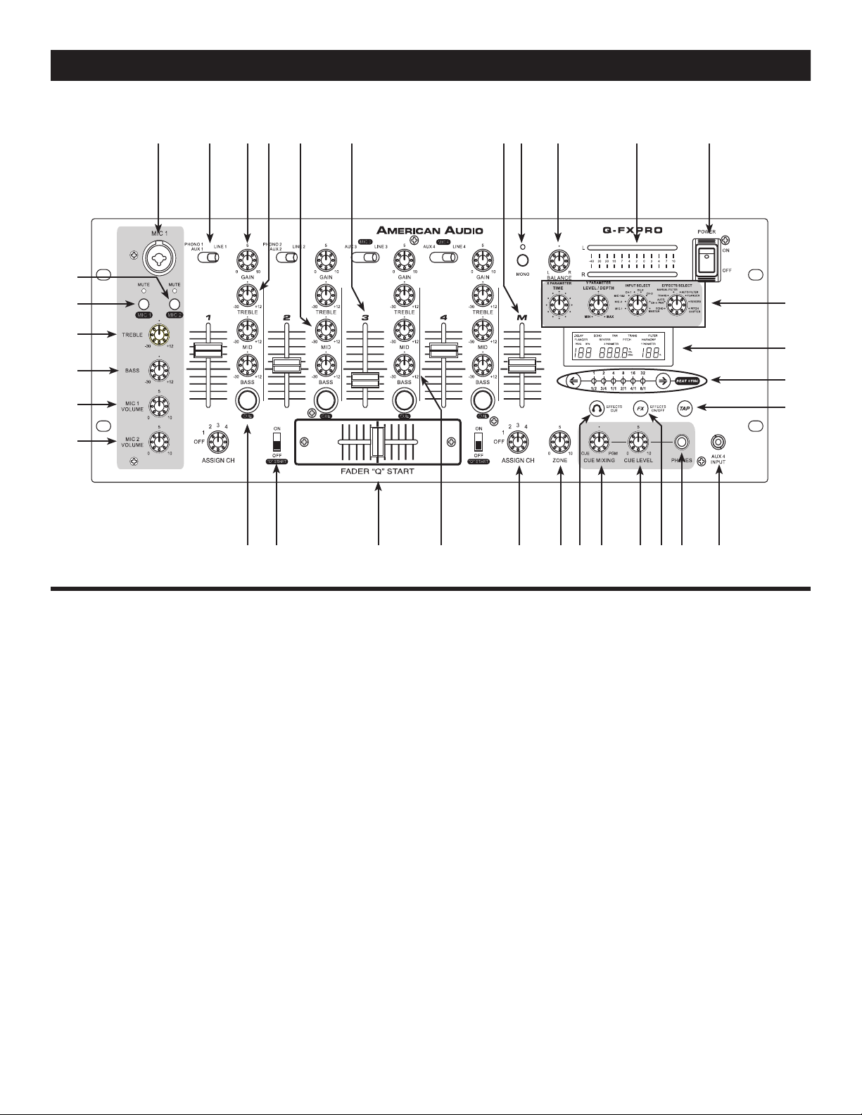
1. MICROPHONE 1 - This combo jack will accept a standard 1/4 plug or XLR 3-pin balanced male
plug. The volume output level for this microphone will be controlled by its own respective CHANNEL
KNOB (29). Note: We recommend that you use a 500-600ohm microphone for the best sound
quality.
2. SOURCE SELECTOR SWITCH - These switches are used to select the input source assigned to
each channel. Each channel may only be assigned one input source at a time. This switch must be in
the “phono” position for turntable operation.
3. CHANNEL GAIN CONTROL - This adjustment is used to adjust the audio source signal input gain
for a channel. Never use the gain control to adjust a channels output volume. Setting the gain level
properly will ensure a clean output signal. An improper gain level adjustment will send a distorted
signal throughout the entire audio line which may damage speakers and amplifiers. To properly set a
channels gain level control:
1. Be sure the MASTER VOLUME CONTROL (
2. Set the CHANNEL FADER (
6) to level 8.
7) is set to level 8.
3. Begin playback on an audio source connected to the channel you are adjusting.
4. Use the Gain Control to adjust an average output volume of +4 dB
.
5. Repeat this step for all channels
4. CHANNEL TREBLE CONTROL - This knob is used to adjust the treble levels of a channel
allowing for a maximum treble gain of 12dB or maximum decrease of -30dB. Turning the knob in
a counter-clockwise direction will decrease the amount of treble applied to a channel signal, turning the knob in a clockwise direction will increase the amount of treble applied to a channel signal.
©American Audio® - www.americanaudio.us - Q-FXPRO Instruction Manual Page 8
Page 9

Q-FXPRO CONTROLS AND FUNCTIONS cont.
5. CHANNEL MIDRANGE CONTROL - This knob is used to adjust the midrange levels of a channel
allowing for a maximum midrange gain of 12dB or maximum decrease of -30dB. Turning the knob in a
counter-clockwise direction will decrease the amount of midrange applied to a channel signal, turning
the knob in a clockwise direction will increase the amount of midrange applied to a channel signal.
6. CHANNEL VOLUME FADER - These faders are used to control the output signal of any source
assigned to its particular channel. However, master volume is controlled by the MASTER VOLUME
CONTROL (7).
7. MASTER VOLUME CONTROL - This slider is used to control the master output level (main volume).
To avoid distorted output try to maintain an average output signal level no greater than +4 dB. (see
Channel Gain 2) To avoid speaker damage that may be caused by excessive volume, be sure this
slider is always set to zero (completely down) before turning the unit on.
8. MASTER OUTPUT MONO/STEREO SWITCH - This switches the Master Output signal between
stereo and mono.
9. MASTER OUTPUT BALANCE CONTROL - This knob is used to control the pan, adjust how much
of the signal is sent to the left and right output level. For true stereo imaging, maintain the knob in the
12 o’ clock position.
10. MASTER VOLUME LEVEL INDICATORS - The dual MASTER LEVEL LED indicator
s are used
to detail the master fader output level. The meters will detail the output level of both the left and right
channels.
11. MAIN POWER SWITCH - This is the main power ON/OFF button. Before main power is applied,
be sure you have made all connections to the mixer. Also be sure your amplifier(s) is(are) tuned off.
Remember to avoid damaging pops to the speakers, the mixer is turned on first and turned off las
t.
12. DSP EFFECTS (DIGITAL SIGNAL PROCESSING)
TIME ARRAY KNOB (PARAMETER X) - This knob is used to adjust the parameter time value.
DEPTH FEEDBACK KNOB (PARAMETER Y) - This knob is used to adjust the parameter ratio
value.
INPUT SELECT - This knob is used to select a channel in which to apply effects.
EFFECTS SELECTOR KNOB - This knob is used to select a desired effect. The effects have
two adjustable parameters, Time Array and Depth Feedback. Effects are listed below;
ECHO - When the ECHO effect is selected it will add an echo to your output signal.
AUTO PAN -
When the PAN effect is selected the effect will automatically pan the output from
the left channel to the right channel.
TRANS - When the TRANS effect is selected it will simulate a real-time mixer transformer
effect.
MANUAL & AUTO FILTER - When the FILTER effect is selected it will tweak the original sound
to add different tonal definition.
FLANGER - When the FLANGER effect is selected distorts the output signal and creates an
effect similar to frequencies phasing in and out of each other.
PITCH SHIFT - When the PITCH SHIFT effect is selected it can increase or decrease the play-
ing speed. Using the BEAT SYNC button you can change the pitch percentange between
- 100%, -50%, 0%, +50%, and +100%.
©American Audio® - www.americanaudio.us - Q-FXPRO Instruction Manual Page 9
Page 10

Q-FXPRO CONTROLS AND FUNCTIONS cont.
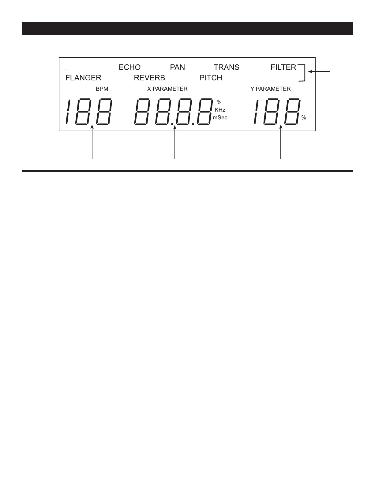
13. LCD SCREEN - FOR INFORMATION SEE PAGE 15.
14. BEAT SELECT BUTTONS/BEAT DISPLAY - This button is used to set the delay time of an effect
to the beat of music. The display indicates the beat ratio that has been set for an effect. The beat ratios
are 1/2, 3/4, 1/1, 2/1, 4/1, and 8/1. It also changes the TIME PARAMETER according to the measured
BPM of the effector.
15. TAP BUTTON - This button is used to override and manually set a tracks BPM. Occasionally the
built-in BPM meter may not function as desired. This button allows you to override the internal beat
clock and manually set a tracks BPMs. To manually set the BPMs; tap this button a few times to a
tracks heavy down beat, the unit will automatically calculate your tapping and translate it into a tracks
BPM. The BPM readout is then displayed in the LCD (13). To return to the automatic BPM counter,
press and hold down the TAP BUTTON for at least 2 seconds and then release.
16. AUX 4 INPUT JACK - This Aux input is for the use of a Mp3 player, or XM or Sirius satellite radio.
Input volume will be controlled by the channel four
17. HEADPHONE JACK -
This jack is used to connect your headphones to the mixer allowing you to
fader
monitor the cue source. Use headphones only rated at 8 ohms to 32 ohms. Most DJ headphones are
rated at 16 ohm, these are highly recommended. Always be sure the CUE LEVEL VOLUME (19) is set
to minimum before you put the headphones on.
18. FX ON/OFF BUTTON - This button functions as an effect Master on/off button and is used to
activate and deactivate the effects.
19. CUE LEVEL VOLUME CONTROL -
This knob is used to adjusts the headphone volume output
level. Turn the knob in a clockwise direction to increase the headphone volume.
20. CUE MIXING CONTROL - This functions allows you to monitor the Cue level as well as the
Program (main output) level in your headphones. A channels Cue Level may only be monitored if the
channels CUE (27) function is selected. To select a channels cue function press the CUE BUTTON
(27) that is directly associated with the specific channel you wish to monitor. You may use the mixing
function to blend both the Cue level and the Program level together. You can vary the output level to
either hear more or less of either of the two levels. Turning the Cue Mixing
(left) will allow you to hear more of the Cue level. Turning the knob to the PGM
knob to the CUE position
position (right) will
allow you to hear more of the Program level (main output). You may also use the Cue Mixing Control
to hear either the Cue level or the Program level exclusively. If the
will only hear the cue level, if the
knob is in the full PGM position you will only hear the main output.
knob is in the full CUE position you
This function is especially useful when mixing without an monitor.
21. FX CUE BUTTON - This is used to select the effects to be monitored with headphones.
22. ZONE LEVEL VOLUME OUTPUT CONTROL - This rotary knob is used to control the zone level
volume. The zone level is not PFL, it is essentially a second master output volume with separate out
-
put volume control.
23. FADER ASSIGN SWITCH - This is a five position switch that assigns a channel to the CROSS-
FADER (25). When a channel is assigned to the left side of the CROSSFADER (25) that channels
output level is routed to and controlled by the CROSSFADER (25). Sliding the CROSSFADER (25) to
left position will send the volume output of the assigned channel to the MASTER VOLUME LEVEL (7),
siding the CROSSFADER (25) to right position will cut that channels volume to MASTER VOLUME
LEVEL (7). The reverse is true for the right channel fader assign switch. When the assign switch is set
to the "OFF" position the crossfader will have no function.
©American Audio® - www.americanaudio.us - Q-FXPRO Instruction Manual Page 10
Page 11

Q-FXPRO CONTROLS AND FUNCTIONS cont.
24. CHANNEL BASS CONTROL - This knob is used to adjust the low frequency levels of a channel
allowing for a maximum bass gain of 12dB or maximum signal decrease of -30dB. Turning the knob
in a counter-clockwise direction will decrease the amount of bass applied to a channel signal, turning
the knob in a clockwise direction will increase the amount of bass applied to a channel signal.
25. FEATHER FADER PLUS CROSSFADER - This fader is used to blend the output signals of channels one and two together. When the fader is in the full left position (channel 1), the output signal of
channel one will be controlled by the master volume level. The same fundamentals will apply for chan
nel two. Sliding the fader from one position to another will vary the output signals of channels one
and two respectively. When the crossfader is set in the center position, the output signals of both the
channels one and channels two will be even.
-
26. Q-START ON/OFF SWITCH -
This function works in conjunction with a compatible American DJ®
or American Audio® “Q” Start CD player. When used with a compatible CD player, you can use the
crossfader to start and stop a CD Player with the slide of the mixer’s CROSSFADER (25). The ON/OFF
“Q" START SWITCH activates the FADER “Q" START feature. When in the ON position, the FADER
“Q" START automatically returns the CD player to the preset CUE POINT.
For example; Assuming you have two compatible American Audio™ CD players or a
compatible dual CD player connected to channels one and two. When the Fader "Q" Start option
is turned on, sliding the crossfader to the far left position will trigger playback on CD player
1. When the crossfader is pushed to the far right position, playback on CD player 2 will
begin, and CD player 1 will return to the cue position. Refer to your American Audio CD
player user manual for setting CUE POINTS. Turn the ON/OFF SWITCH to the OFF
position to disengaged “Q” Start function and resume to a normal fader.
27. CUE SELECTOR BUTTON - These buttons are used to activate a channels “CUE” mode. The
red CUE LED will glow when a channels cue mode is activated. The Cue function sends a channels
incoming signal to the headphones. The cue level is adjusted by the CUE LEVEL KNOB (19). Be sure
the CUE MIXING KNOB (20) is set to the “CUE” position to hear a selected channel source.
28. MIC 2 VOLUME CONTROL - This knob controls the output volume of MICROPHONE 2 (36).
However, master volume is controlled by the MASTER VOLUME CONTROL (7).
29. MIC 1 VOLUME CONTROL - This knob controls the output volume of MICROPHONE 1 (1).
However, master volume is controlled by the MASTER VOLUME CONTROL (7).
30. MICROPHONE BASS CONTROL - This knob is used to adjust the low frequency levels of the micro-
phone with a maximum signal gain of 12dB or maximum signal decrease of -30dB. Turning the knob in
a counter-clockwise direction will decrease the amount of bass applied to the microphone signal, turning the knob in a clockwise direction will increase the amount of bass applied to microphone signal.
. MICROPHONE TREBLE CONTROL - This knob is used to adjust the treble levels of the
31
Microphone with a maximum signal gain of 12dB or maximum signal decrease of -30dB. Turning the
knob in a counter-clockwise direction will decrease the amount of treble applied to the microphone signal,
turning the knob in a clockwise direction will increase the amount of treble applied to microphone signal.
32. MIC 1 ON/OFF BUTTON - This switches MIC 1 On and Off.
33. MIC 2 ON/OFF BUTTON - This switches MIC 2 On and Off.
©American Audio® - www.americanaudio.us - Q-FXPRO Instruction Manual Page 11
Page 12
Q-FXPRO CONTROLS AND FUNCTIONS cont.
REAR PANEL
51 50 49
4445485254 43 3747 46 42 41 38 40 39 38 3653
34 34
35
34. GND (GROUND TERMINAL) - Be sure to connect turntable ground leads to either or both of
the two available ground terminals. This will reduce the humming and popping noises associated
with magnetic phono cartridges.
35. MICROPHONE 3 CONNECTOR - This jack is used to a connect a microphone to the mixer. Connect you microphone via this 1/4 inch (6.3mm) jack. This microphone will be controlled through the
channel 3 fader. The channel 3 EQ will also effect the microphone output. Be sure to flip the SOURCE
SELECTOR SWITCH (2) to the “MIC 3” position to operate this microphone’s input signal.
36. MICROPHONE 2 CONNECTOR - This jack is used to a connect a microphone to the mixer.
Connect you microphone via this 1/4 inch (6.3mm) jack. The volume output level for this microphone
will be controlled by its own respective CHANNEL KNOB (28).
37. MICROPHONE 4 CONNECTOR - This jack is used to a connect a microphone to the mixer. Con
nect you microphone via this 1/4 inch (6.3mm) jack. This microphone will be controlled through the
channel 4 fader. The channel 4 EQ will also effect the microphone output. Be sure to flip the SOURCE
SELECTOR SWITCH (2) to the “MIC 4” position to operate this microphone’s input signal.
38. CHANNEL LINE LEVEL SELECTOR SWITCHES - These switches are used to change the voltage line levels of there respected Phono / Aux RCA inputs jacks. When connecting turntables with
magnetic cartridges to these jacks be sure the corresponding switch is in the “PHONO” position,
and when using line level input devices be sure this switch is in the “AUX” position. Always be sure
main power is shut off before change the position of the Line Level Selector Switch.
39. CHANNEL 1: PHONO 1/AUX 1 INPUT - The type of input must directly reflect the selected
mode of the LINE LEVEL SELECTOR SWITCH (38). Turntables equipped with MM pickup cartridge
(All DJ turntable use MM pick-up cartridges) may be connected to these jacks as long as the LINE
LEVEL SELECTOR SWITCH (38) is in the “PHONO 1” position. CD players, Tape Decks and other
line level instruments may only be connected to these jacks as long as the LINE LEVEL SELECTOR SWITCH (38) is in the “AUX 1” position. Never connect line level instruments (CD players, tape
decks, etc.) to these jacks when the LINE LEVEL SELECTOR SWITCH (38) is in the “PHONO 1” position, THIS MAY SERIOUSLY DAMAGE YOUR MIXER! The red colored RCA jack represents the right
channel input and the white represents the left channel input. Input volume will be controlled by the
channel three fader. The channel SOURCE SELECTOR SWITCH (2) must be in the "Phono 1/Aux 1"
position, to monitor any source connected to these jacks.
©American Audio® - www.americanaudio.us - Q-FXPRO Instruction Manual Page 12
Page 13

Q-FXPRO CONTROLS AND FUNCTIONS cont.
40. CHANNEL 1: LINE 1 INPUT JACKS - DO NOT CONNECT TURNTABLES TO THESE JACKS!
CD players, Tape Decks and other line level instruments may be connected to these jacks. The red
colored RCA jack represents the right channel input and the white represents the left channel input.
Input volume will be controlled by channel three fader. The channel SOURCE SELECTOR SWITCH
(2) must be in the "Line 1" position, to monitor any source connected to these jacks.
41. CHANNEL 2: PHONO 2/AUX 2 INPUT - The type of input must directly reflect the selected
mode of the
(All DJ turntable use MM pick-up cartridges) may be connected to these jacks as long as the LINE
LEVEL SELECTOR SWITCH (38) is in the “PHONO 2” position. CD players, Tape Decks and other
line level instruments may only be connected to these jacks as long as the LINE LEVEL SELECTOR SWITCH (38) is in the “AUX 2” position. Never connect line level instruments (CD players, tape
decks, etc.) to these jacks when the LINE LEVEL SELECTOR SWITCH (38) is in the “PHONO 2” position, THIS MAY SERIOUSLY DAMAGE YOUR MIXER! The red colored RCA jack represents the right
channel input and the white represents the left channel input. Input volume will be controlled by the
channel three fader. The channel SOURCE SELECTOR SWITCH (2) must be in the "Phono 2/Aux 2"
position, to monitor any source connected to these jacks.
LINE LEVEL SELECTOR SWITCH (38). Turntables equipped with MM pickup cartridge
42. CHANNEL 2: LINE 2 INPUT JACKS - DO NOT CONNECT TURNTABLES TO THESE JACKS!
CD players, Tape Decks and other line level instruments may be connected to these jacks. The red
colored RCA jack represents the right channel input and the white represents the left channel input.
Input volume will be controlled by channel three fader. The channel SOURCE SELECTOR SWITCH
(2) must be in the "Line 2" position, to monitor any source connected to these jacks.
43. CHANNEL 3: AUX 3 INPUT - The type of input must directly reflect the selected mode of the
LINE LEVEL SELECTOR SWITCH (38). CD players, Tape Decks and other line level instruments may
only be connected to these jacks as long as the LINE LEVEL SELECTOR SWITCH (38) is in the “AUX
3” position. Never connect line level instruments (CD players, tape decks, etc.) to these jacks when
the LINE LEVEL SELECTOR SWITCH (38) is in the “PHONO 3” position, THIS MAY SERIOUSLY
DAMAGE YOUR MIXER! The red colored RCA jack represents the right channel input and the white
represents the left channel input. Input volume will be controlled by the channel three fader. The
channel SOURCE SELECTOR SWITCH (2) must be in the "Phono 3/Aux 3" position, to monitor any
source connected to these jacks.
44. CHANNEL 3: LINE 3 INPUT JACKS - DO NOT CONNECT TURNTABLES TO THESE JACKS!
CD players, Tape Decks and other line level instruments may be connected to these jacks. The red
colored RCA jack represents the right channel input and the white represents the left channel input.
Input volume will be controlled by channel three fader. The channel SOURCE SELECTOR SWITCH
(2) must be in the "Line 3" position, to monitor any source connected to these jacks.
45. CHANNEL 4: LINE 4 INPUT JACKS - These Jacks are used for line level inputs. Connect CD
players or Tape Decks to line level inputs. Line level musical instruments with stereo outputs such as
Rhythm Machines or Samplers should also be connected to line level inputs. The red colored RCA
jack represents the right channel input and the white represents the left channel input. Input volume
will be controlled by the channel four
fader. Do not connect turntables to these jacks, turntables
should only be connected to “Phono” inputs.
46. REC OUTPUT JACKS - This is a low current unbalanced output source designed for various
tape and CD recorders. The Record Out (REC OUT) level is dictated by the
CHANNEL FADER LEVEL
(6), it is not influenced by the MASTER VOLUME CONTROL (7).
47. ZONE LEVEL OUTPUT - Use this separate output signal to drive a booth monitor or separate
©American Audio® - www.americanaudio.us - Q-FXPRO Instruction Manual Page 13
Page 14

Q-FXPRO CONTROLS AND FUNCTIONS cont.
sound system. The output level for these jacks will be controlled by the ZONE VOLUME KNOB
(22). These RCA jacks send a low current, unbalanced output signal. These jacks should only be
used for shorter cable runs (under 15 feet) to signal processors or looping to another mixer.
48. RCA MASTER OUTPUTS - The Master Output includes a pair
XLR BALANCED JACKS (52)
as well as a pair of RCA Unbalanced Jacks. The RCA jacks send a low current unbalanced output
signal. These jacks should only be used for shorter cable runs to signal processors or looping to
another mixer. For cable runs greater than 15 feet use the
XLR BALANCED JACKS (52).
49. PLAYER A CONTROL - This jack is used to control the “Q-Start” function between the mixer
and a compatible American Audio
® or American DJ® CD Player. Using the mini plug included with
your CD player, connect from the CD player controller out jack to this jack. Player A “Q-Start”
functionallity will be controlled by the left side of the CROSSFADER (25). For more information on
“Q-Start” functionallity refer to the user manual included with your CD player. Be sure to only use
the mono tip mini plug included with your CD player to avoid damage to the mixer and/or the CD
player.
50. PLAYER B CONTROL - This jack is used to control the “Q-Start” function between the mixer
and a compatible American Audio
® or American DJ® CD Player. Using the mini plug included with
your CD player, connect from the CD player controller out jack to this jack. Player B “Q-Start”
functionallity will be controlled by the right side of the CROSSFADER (25). For more information on
“Q-Start” functionallity refer to the user manual included with your CD player. Be sure to only use
the mono tip mini plug included with your CD player to avoid damage to the mixer and/or the CD
player.
51. TRIM OUTPUT -
This knob is used to adjust the maximum voltage output level. Output voltage
wil range from 0v ~ 9v. This function may be used to limit the maximum siganl output level.
52. BALANCED XLR MASTER OUTPUTS JACKS - The Master Output includes a pair of XLR
Balanced jacks as well as a pair of RCA UNBALANCED JACKS (48)
. The 3-pin XLR jacks send a
high current balanced output signal. These jacks should be used when you will be driving an amp or
other audio equipment with a balanced input, or whenever you will be running a signal line greater
than 15 feet. Always, use these jacks whenever possible.
53. AC CONNECTION -
This connector is used to supply main power to the unit via the included
detachable power cord. The power connection uses an I.E.C. type connector, use only the supplied,
polarized AC power cord. Use only a power cord that matches this type of connection. Be sure to
only connect this unit to a power outlet that matches the printed power label on the unit. Never use
a power cord when the ground prong has been removed or broken off. The ground prong is used to
reduce the risk of electrical shock in case of an electrical short. This cord is designed to fit in one
direction only. Do not attempt to force a cord if it does not fit, be sure the cord is being inserted
properly.
54. AC VOLTAGE SELECTOR - This switch is used to change the operating voltage. Operating
voltage can be toggled between 115v or 230v/50~60Hz. Be sure the selector is set to the proper
voltage for your area before attempting to operate the unit. Always be sure main power is shut off
before change the position of the Voltage Selector Switch.
©American Audio® - www.americanaudio.us - Q-FXPRO Instruction Manual Page 14
Page 15
Q-FXPRO DSP EFFECT CONTROLS AND FUNCTIONS
58 57 56 55
55. EFFECTS INDICATOR - When any of the eight effects are in use, these indicators will glow to
match any of the eight effects that may be functioning.
56. DEPTH FEEDBACK DISPLAY - The Depth Feedback digital display will indicate the parameter
ratio percentage. Turning the DEPTH FEEDBACK KNOB (12) in a clockwise direction will increase your
ratio percentage. Turning the knob in a counter-clockwise direction will decrease the ratio percent
age.
-
57. TIME ARRAY DISPLAY - This display will signify the pitch percentage (speed). Any adjustments
will be based on this default setting. Turning the knob in a clockwise direction will increase your pitch.
Turning the knob in a counter-clockwise direction will decrease the pitch.
58
. BPM (BEATS PER MINUTE) DISPLAY - This meter will display the master output BPMs.
©American Audio® - www.americanaudio.us - Q-FXPRO Instruction Manual Page 15
Page 16
Q-FXPRO TYPICAL MIXER SET-UP
C A S S E T T E D E C K
T U R N TA B L E
T U R N TA B L E
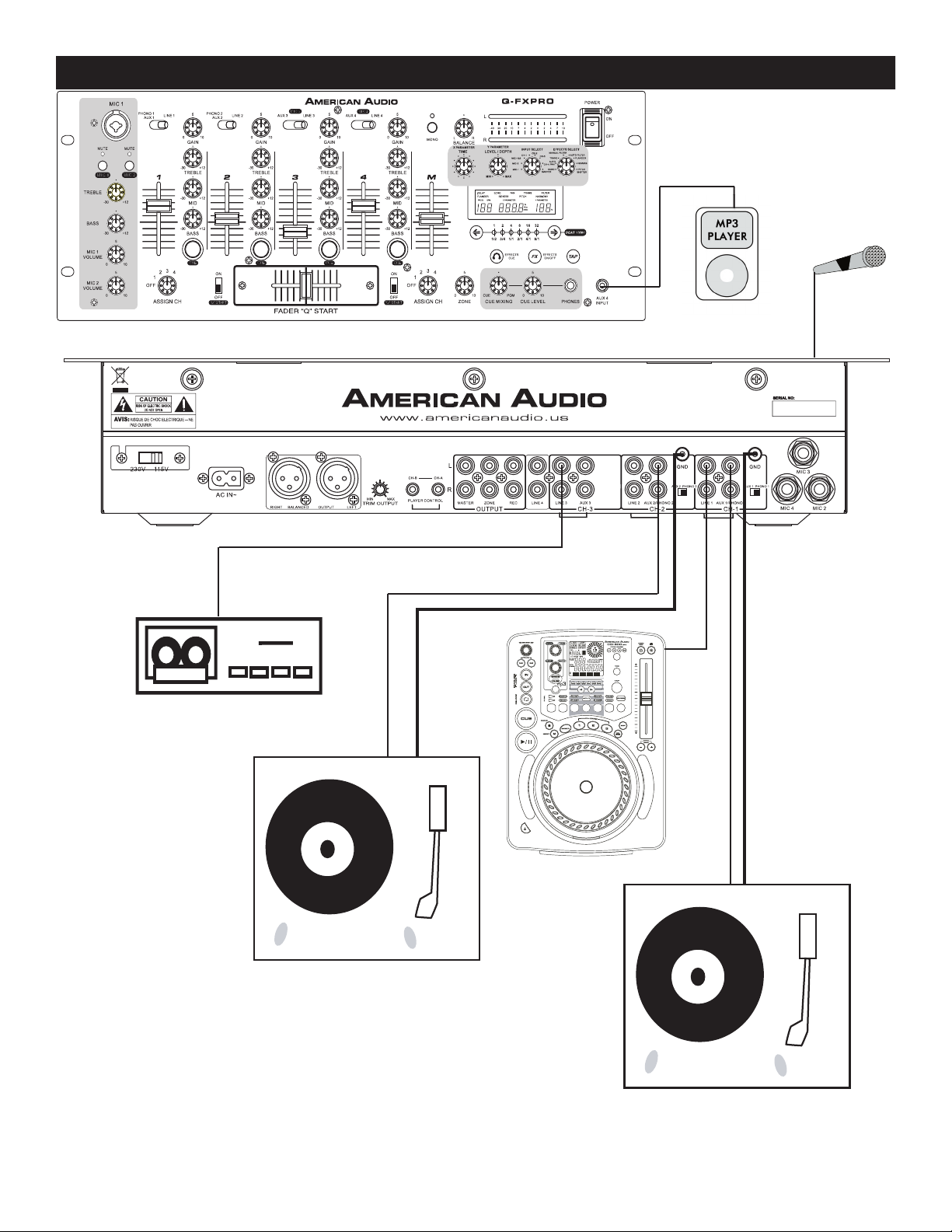
This image details a typical DJ Set Up consisting of a microphone, turntables, CD players, and a tape deck.
Note: Turntables can only be connected to the PHONO LEVEL RCA
JACKS. Be sure the LINE LEVEL SELECTOR SWITCHES are in the
"PHONO" position when using turntables.
©American Audio® - www.americanaudio.us - Q-FXPRO Instruction Manual Page 16
Page 17
Q-FXPRO TYPICAL MIXER SET-UP
C A S S E T T E D E C K
Balanced XLR male to XLR female Cables
American Audio V4001™
Speaker Cables
RCA to RCA Patch Cables
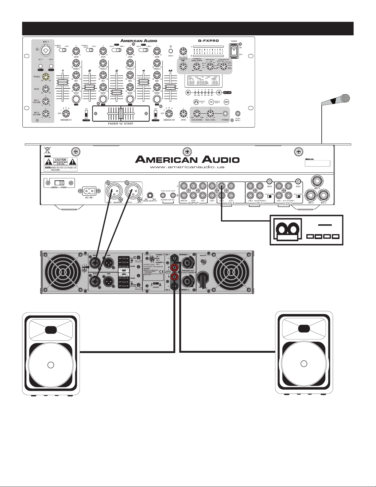
Typical Balanced Output Set-up
This image details a typical stereo output layout. Note the use of the Balanced XLR Jacks on both
the mixer and the amplifier. Always use the balanced output jacks whenever possible. The balanced
output jacks should always be used for cable runs in excess of 15 feet.
Using the balanced jacks will ensure a clean signal through out the entire audio system.
©American Audio® - www.americanaudio.us - Q-FXPRO Instruction Manual Page 17
Page 18
Q-FXPRO CLEANING
Due to fog residue, smoke, and dust, cleaning the mixer should be carried out periodically to residue
build up.
1. Use normal glass cleaner and a soft cloth to wipe down the outside casing.
2. Use a cleaner specially designed for electronics to spray in and around the knobs and switch.
This will reduce small particle built up that can effect the proper operation of the mixer.
3. Cleaning should be carried out every 30-60 days to prevent heavy built up.
4. Always be sure to dry all parts completely before plugging the mixer in.
Cleaning frequency depends on the environment in which the mixer operates (i.e. smoke, fog residue,
dust, dew).
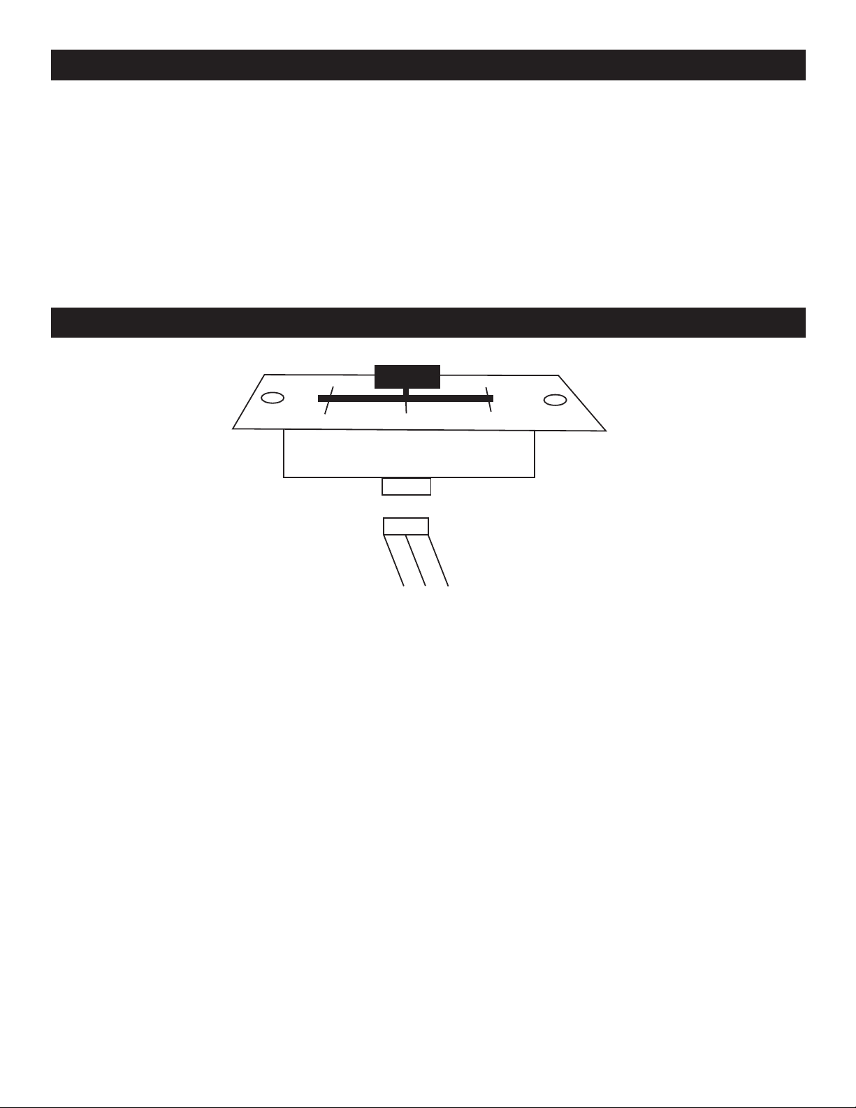
Q-FXPRO CROSS FADER REPLACEMENT
The crossfader is “Hot Swapable” which means it may be replaced at any time, even when power is
applied. Only replace with American Audio Part Feather Fader Plus. Replacing with any other model
fader may seriously damage your mixer.
Replacing the Crossfader:
1. Disconnect the mixers main power supply
2. Using a number two Phillips screw driver, unscrew the each of the stainless steel retain screws
that hold the crossfader in place.
3. Gently remove the crossfader from its seated position. You may need to wiggle the crossfader
slightly to remove it.
4. After removing the crossfader, disconnect the ribbon cable that attaches the crossfader to the
PC board. Grasp the crossfader by its base and pull the ribbon cable by its connector not the
actual cables. The connector is designed to only fit one way, so don’t worry about the connec
tors orientation.
5. Connect the new crossfader to the ribbon cable and replace in reverse order.
©American Audio® - www.americanaudio.us - Q-FXPRO Instruction Manual Page 18
Page 19

Q-FXPRO TROUBLESHOOTING
Trouble Shooting: Listed below are common problems you may encounter, and solutions.
There is no power to the unit:
Be sure you have connected the power cord to a correct wall outlet.
There is little or no sound:
1. Check the input selector switch. Make sure it is set to the device that is currently playing.
2. Check to see if the connection cables are connected properly.
3. Check the Trim Output level control on the rear panel, make sure it is not set to low.
The sound is distorted:
1. Check the Trim Output level control on the rear panel, make sure it is not set to high.
2. Make sure that the Gain level control is not set to high.
Crossfader is not working:
Check and see if any channels have been assigned to the crossfader.
Effects are not working:
1. Check to see if the effects have been activated. Activate them by pressing the “FX ON” button.
2. Make sure a channel has been selected in which to apply effects to.
Cannot measure BPM, or measured BPMs seem incorrect:
Sometimes the BPM cannot be measured, depending on the music. If this happens, you will
have to set the BPM manually, by using the TAP button (15). See TAP button (15) on page 10.
©American Audio® - www.americanaudio.us - Q-FXPRO Instruction Manual Page 19
Page 20

Q-FXPRO WARRANTY
The Q-FXPRO carries a one year limited warranty. We recommend you fill out the enclosed warranty
card to validate your purchase. All returned service items whether under warranty or not, must be freight
pre-paid and accompany a R.A. (return authorization) number. If the mixer is under warranty, you must
provide a proof of purchase invoice. You may obtain a R.A. number by contacting our customer support
team on our toll free number.
for a R.A. number. All package not displaying a R.A. number on the outside of the package will
be returned to the shipper.
1-YEAR LIMITED WARRANTY
Please contact American Audio® customer support at (800) 322-6337
A. American Audio
® hereby warrants, to the original purchaser, American Audio® products to be free
of manufacturing defects in material and workmanship for a period of 1 Year (365 days) from the date
of purchase. This warranty shall be valid only if the product is purchased within the United States of
America, including possessions and territories. It is the owner’s responsibility to establish the date and
place of purchase by acceptable evidence, at the time service is sought.
B. For warranty service, send the product only to the American Audio
® factory. All shipping charges
must be pre-paid. If the requested repairs or service (including parts replacement) are within the terms
of this warranty, American Audio® will pay return shipping charges only to a designated point within
the United States. If the entire instrument is sent, it must be shipped in its original package. No accessories should be shipped with the product. If any accessories are shipped with the product, American
Audio® shall have no liability whatsoever for loss of or damage to any such accessories, nor for the
safe return thereof.
C. This warranty is void if the serial number has been altered or removed; if the product is modified in
any manner which American Audio
® concludes, after inspection, affects the reliability of the product;
if the product has been repaired or serviced by anyone other than the American Audio® factory unless
prior written authorization was issued to purchaser by American Audio®; if the product is damaged
because not properly maintained as set forth in the instruction manual.
D. This is not a service contract, and this warranty does not include maintenance, cleaning or peri
odic check-up. During the period specified above, American Audio® will replace defective parts at
its expense, and will absorb all expenses for warranty service and repair labor by reason of defects
in material or workmanship. The sole responsibility of American Audio
® under this warranty shall be
limited to the repair of the product, or replacement thereof, including parts, at the sole discretion of
American Audio®. All products covered by this warranty were manufactured after January 1, 1990, and
bear identifying marks to that effect.
E. American Audio
® reserves the right to make changes in design and/or improvements upon its prod-
ucts without any obligation to include these changes in any products theretofore manufactured.
F. No warranty, whether expressed or implied, is given or made with respect to any accessory sup
plied with products described above. Except to the extent prohibited by applicable law, all implied
warranties made by American Audio® in connection with this product, including warranties of merchantability or fitness, are limited in duration to the warranty period set forth above. And no warranties, whether expressed or implied, including warranties of merchantability or fitness, shall apply to
this product after said period has expired. The consumer’s and or Dealer’s sole remedy shall be such
repair or replacement as is expressly provided above; and under no circumstances shall American
Audio® be liable for any loss or damage, direct or consequential, arising out of the use of, or inability
to use, this product.
G. This warranty is the only written warranty applicable to American Audio® Products and supersedes
all prior warranties and written descriptions of warranty terms and conditions heretofore published.
©American Audio® - www.americanaudio.us - Q-FXPRO Instruction Manual Page 20
Page 21

Q-FXPRO SPECIFICATIONS
Model: Q-FXPRO 4 Channel Mixer
POWER SUPPLY: AC 115v~60Hz/230v~50Hz, User Selectable
Single Voltage:
AC 100V, 50/60Hz (Japan); AC 110V, 60Hz (Colombia)
AC 120V, 60Hz (U.S.A. and Canada); AC 127V, 60Hz (Mexico)
AC 220V, 50Hz (Chile and Argentina); AC 240V, 50Hz (Australia)
AC 220V, 60Hz (Philippines and Korea)
AC 230V, 50Hz (Europe, U.K., New Zealand, South Africa, and Singapore)
DIMENSIONS: 482.6mm (W) x 177mm (D) x 109.6mm (H)
19” (W) x 6.9” (D) x 4.31” (H)
WEIGHT: 8.4 Lbs. / 3.8 Kgs.
CROSSFADER: Feather Fader Plus - VCA detecting fader start control -
Low grounding impedance crossfader
POWER CONSUMPTION: 19.5W
HEADPHONE IMPEDANCE: 16 Ohms
OPERATING TEMPERATURE: 5 to 35 deg. C; Humidity: 25 to 85% RH
(non-condensing); Storage Temperature: -20 to 60 deg. C
Input/Output Impedance & Sensitivity: (EQ Flat, Maximum Gain, FX Off, Load = 100K OHM)
LINE: 10K OHM / -14dBV (200mV)
AUX: 47K OHM / -14dBV (200mV)
PHONO: 47K OHM / -54dBV (2mV)
MIC: 10K OHM / -54dBV (2mV)
REC: 2.2K OHM / -10dBV (316mV) +/-2dB
MASTER UNBAL.: 1K OHM / 0dBV (1V) +/-2dB
MASTER XLR (load=600 OHM): 600 OHM / +4dBm (1.23V) +/-2dB
ZONE: 1K OHM / 0dBV (1V) +/-2dB
PHONES (load=32 OHMS): 33 OHM / 0dBV (1V) +/-2dB
Maximum Input: (1KHz Input, Master Output THD=10%, EQ Flat, FX Off, Maximum Gain)
LINE, AUX: MORE THAN +4dBV
PHONO: MORE THAN -36dBV
MIC: MORE THAN -36dBV
Maximum Output: (EQ Flat, Maximum Gain, FX Off, THD=10%)
MASTER/ZONE: MORE THAN +18 dBV (8.0V)
PHONES: (LOAD=32 ohms) MORE THAN +3dBV (1.4V)
CHANNEL BALANCE: WITHIN 3dB
Frequency Response:
LINE/AUX: 20 - 20KHz +/-2dB
PHONO: 20 - 20KHz +2 /-3dB (RIAA)
MICROPHONE: 20 - 20KHz +2 /-3dB
THD - Total Harmonic Distortion: (EQ Flat, Maximum Gain, FX Off, W/ 20KHz LPF):
LINE, AUX: LESS THAN 0.05% 20 - 20KHz
PHONO: LESS THAN 0.15% @ 1KHz (A-Weighted)
MIC: LESS THAN 0.2% @ 1KHz (A-Weighted)
CROSS TALK: Maximum Gain, EQ Flat, Master Output)
LINE, AUX, PHONO: More Than 60dB @ 1KHz Between L and R, and Channels
Channel Equalizer:
BASS: +12 ±2dB,-31 ±3dB at 70Hz
MID: +12 ±2dB, Below -27dB at 1KHz
TREBLE: +12 ±2dB,-14 ±3dB at 13KHz
Microphone Equalizer:
BASS: +12 ±2dB, -22 ±2dB, at 100Hz
TREBLE: +12 ±2dB, -15 ±2dB, at 10KHz
©American Audio® - www.americanaudio.us - Q-FXPRO Instruction Manual Page 21
Page 22

©American Audio® World Headquarters:
4295 Charter Street Los Angeles, CA 90058 USA
Tel: 323-582-3322 Fax: 323-582-2941
Web: www.americanaudio.us E-mail: [email protected]
 Loading...