

Page 1
Sampling
Sampling
FLIPFLOP
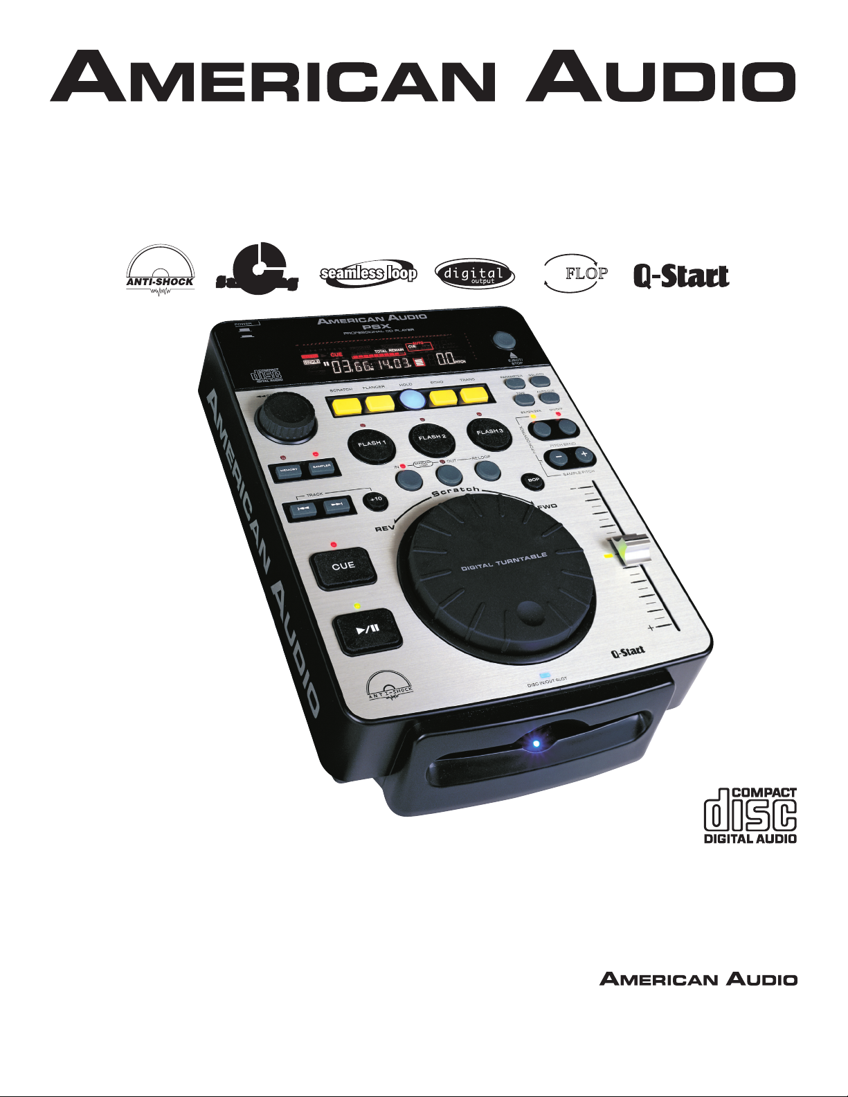
PSX
Featuring:
™
Rev 02/04
User Guide
and Reference Manual
4295 Charter Street
Los Angeles Ca. 90058
www.americanaudio.us
Page 2

CONTENTS
SAFETY REGULATIONS.........................................................................................................................3
ELECTRICAL PRECAUTIONS.................................................................................................................4
SAFETY INSTRUCTIONS ........................................................................................................................5
VOLTAGE SELECTOR.............................................................................................................................5
UNPACKING........................................................................................................................................6
INTRODUCTION....................................................................................................................................6
CUSTOMER SUPPORT..........................................................................................................................6
FEATURES............................................................................................................................................7
SET-UP INSTALLATION...........................................................................................................................8
FUNCTIONS AND CONTROLS
MAIN UNIT...................................................................................................................................9
LCD DISPLAY................................................................................................................................12
BASIC OPERATIONS
LOADING EJECTING DISC.......................................................................................................13
SELECTING TRACKING............................................................................................................13
STARTING PLAYBACK..............................................................................................................14
PAUSING PLAYBACK...............................................................................................................14
FRAME SEARCH.......................................................................................................................14
TRACK SCANNING (FAST FWD/FAST REV).............................................................................15
SETTING AND STORING CUE POINTS...................................................................................15
CREATING A SEAMLESS LOOP...............................................................................................16
USING THE BUILT-IN SAMPLER..............................................................................................18
CREATING A BOP EFFECT......................................................................................................20
USING FLASH START BUTTONS.............................................................................................21
CHANGING TIME DISPLAY.......................................................................................................21
PITCH ADJUSTMENTS
PITCH SLIDER...........................................................................................................................22
PITCH BENDING.......................................................................................................................23
SYSTEM MEMORY...............................................................................................................................24
BUILT-IN EFFECTS
SCRATCH................................................................................................................................25
FLANGER...........................................................................................................................25
ECHO......................................................................................................................................25
ROBOT.....................................................................................................................................25
TRANS......................................................................................................................................26
CHANGING PARAMETERS.......................................................................................................26
FLIP-FLOP™...................................................................................................................................27
WARRANTY.....................................................................................................................................28
SPECIFICATIONS.................................................................................................................................31
Specifications and changes to this manual and the PSX™ are subject to change at any time without and prior notice written
©American Audio® - www.americanaudio.us - PSX™ Instruction Manual Page 2
Page 3
IMPORTANT SAFETY ITEMS FOR
U.S.A. & CANADA MODEL ONLY
NOTE:
This CD player uses a semiconductor laser.
It is recommended for use in a room at the
following temperature: 41˚F - 95˚F / 5˚C - 35˚C
WARNING:
TO PREVENT FIRE OR SHOCK HAZARD,
DO NOT EXPOSE THIS CD PLAYER TO
WATER OR MOISTURE
CAUTION:
1. Handle the power supply cord carefully. Do not
damage or deform; it may cause electric shock
or malfunction when used. Hold plug attach ment when removing from wall outlet. Do not
pull on the cord.
2. To avoid electric shock, do not open the top
cover when the unit is plugged in. If problems
occur with the unit, call your local American
Audio® dealer.
3. Do not place metal objects or spill liquid inside
the CD player. Electric shock or malfunction
may occur.
CAUTION
Do not open -
risk of electric shock
CAUTION: TO REDUCE THE RISK OF ELECTRIC
SHOCK, DO NOT REMOVE THE COVER RACK.
THERE ARE NO USER SERVICEABLE PARTS
INSIDE REFER SERVICE TO YOUR
AUTHORIZED American Audio DEALER.
The lightning flash with an arrow triangular
symbol is intended to alert the user to
the presence of non insulated “dangerous
voltage” within the products enclosure, and
may be of sufficient magnitude to constitute
a risk of electric shock.
The exclamation point triangular symbol is
intended to alert the user to the presence
of important operating and maintenance
(servicing) instructions in the user manual
accompanying the CD player.
CAUTION
TO PREVENT ELECTRIC SHOCK DO NOT USE THIS
(POLARIZED) PLUG WITH AN EXTENSION CORD,
RECEPTACLE OR OTHER OUTLET UNLESS THE BLADES
CAN BE CAREFULLY INSERTED TO PREVENT BLADE
EXPOSURE
CAUTION:
USE OF CONTROLS OR ADJUSTMENTS OTHER
THAN THOSE SPECIFIED HEREIN MAY RESULT
IN HAZARDOUS RADIATION EXPOSURE
THE COMPACT DISC PLAYER SHOULD NOT BE
ADJUSTED OR REPAIRED BY ANYONE EXCEPT
PROPERLY QUALIFIED SERVICE PERSONNEL.
NOTE:
This unit may cause interference to radio and
television reception.
Please carefully read and understand the instructions in this manual thoroughly before attempting to operate this unit. These instructions
contain important safety information regarding
the use and maintenance of this unit. Take special care to follow all warning symbols and labels
both on the unit and printed in this manual. Also,
Please keep this manual with the unit, for future
reference.
CAUTION: TO PREVENT ELECTRIC SHOCK
DO NOT USE THIS (POLARIZED) PLUG
WITH AN EXTENSION CORD, RECEPTACLE,
OR OTHER TYPE OF ELECTRICAL OUTLET
UNLESS THE WIDE BLADES CAN BE
CAREFULLY INSERTED INTO A MATCHING
WIDE SLOT.
ATTENTION: POUR PREVENIR LES CHOCS
ELECTRIQUES NE PAS UTILISER CETTE
FICHE POLARISEE AVEC UN PROLONGATEUR, UNE PRISE DE COURANT OU
UNE AUTRE SORTIE DE COURANT, SAUF SI
LES LAMES PEUVENT ETRE INSEREES A
FOND SANS EN LAISSER AUCUNE PARTIE
A DECOUVERT.
©American Audio® - www.americanaudio.us - PSX™ Instruction Manual Page 3
Page 4
ELECTRICAL SAFETY PRECAUTIONS
ELECTRICAL PRECAUTIONS
CAUTION
RISK OF ELECTRIC SHOCK
DO NOT OPEN
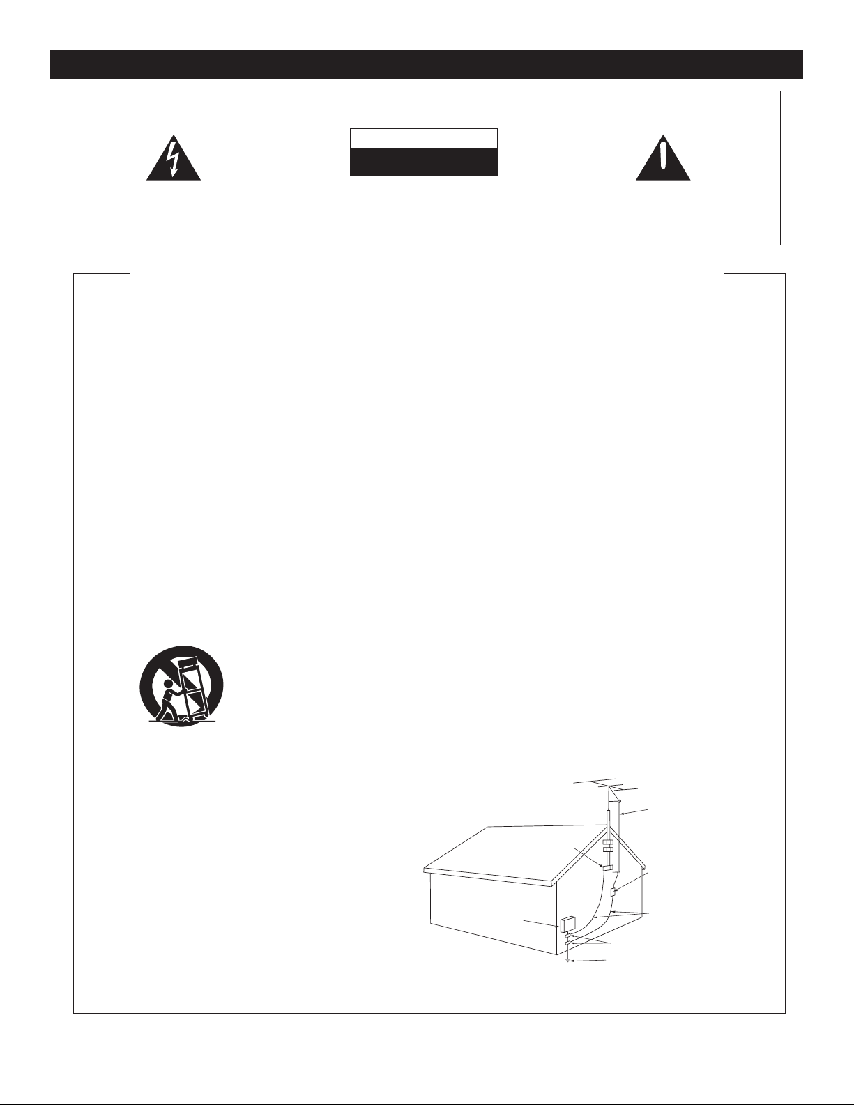
The lightning flash with arrowhead symbol, within an
equilateral triangle, is intended to alert the user to the
presence of uninsulated "dangerous voltage" within the
product's enclosure that may be of sufficient magnitude
to constitute a risk of electric shock to persons.
CA UTI ON : T O R ED UC E TH E R ISK OF ELE CT RI C
SHOCK, DO NOT REMOVE THE COVER (OR BACK).
T HE RE AR E N O U SE R S ER V ICE AB LE PA RT S
INS IDE REF ER SERV ICE TO YOUR AUTHO RIZED
AMERICAN AUDIO® SERVICE TECHNICIAN.
IMPORTANT SAFETY INSTRUCTIONS
READ INSTRUCTIONS — All the safety and operating
instructions should be read before the product is
operated.
RETAIN INSTRUCTIONS — The safety and operatin
instructions should be retained for future reference.
HEED WARNING
in the operating instructions should be adhered to.
FOLLOW INSTRUCTIONS — All operating and use
instructions should be followed.
CLEANING
a polishing cloth or a soft dry cloth. Never clean with
furniture wax, benzine, insecticides or other volatile
liquids since they may corrode the cabinet
ATTACH MENTS — Do no t use attachmen ts not
recommended by the product manufacturer as they
may cause hazards.
WATER AND MOISTURE
near
bowl, kitchen sink, or laundry tub; in
or near a swimming pool; and the like.
ACCESSORIES
unstable cart, stand, tripod, bracket, or table. Th
product may
adult, and serious damage to the product. Use only
with a cart, s tand , tr ipod , brack et, or tabl e
recommended by the manufacturer, or sold
the product. Any mounting of the product shoul
follow the manufacturer’s instructions, and should
use
manufacturer
CART — A product and cart combination should be
moved
uneven surfaces may cause the product and car
combination to overturn
VENTILATION
provided for ventilation and to e nsure reliab l
operation of the product and
overheating, and these openings must not be
blocked or covered. The openings should never be
blocked by placing the product on
or other
placed
rack unless proper ventilation
manufacturer’s instructions have been adhered
POWER SOURCES
only from the type of power source indicated on
marking label.
power supply
dealer or local power company.
LOCATIO
stable location.
NONUSE PERIOD
should be unplugged from the
used for a long period of time.
S — All warnings on the product and
— The product should be cleaned only with
.
water — for example, near a bathtub, wash
a mounting accessory recommended by the
with care. Quick stops, excessive force, and
— Slots and openings in the cabinet are
similar surface. This product should not be
in a built-in installation such as a bookcase or
N – The appliance should be installed in a
— Do not use this product
a wet basement;
— Do not place this product on an
fall, causing serious injury to a child or
with
.
.
to protect it from
a bed, sofa, rug,
is provided or the
— This product should be operated
If you are not sure of the type of
to your home, consult your product
S – The power cord of the appliance
outlet when left un-
the
g
e
d
t
e
to.
GROUNDING OR POLARIZATION
• If this product is equipped with a polarized alternating
current line plug
the other),
it will fit into the outlet only one way. This
is a safety feature. If you are unable to insert the plug
fully into the outlet, try reversing the plug. If the plug
should
still fail to fit, contact your electrician to
replace your obsolete outlet. Do not defeat the
safety purpose of the polarized plug.
• If this product is equipped wi th a three-wire
grounding type plug,
pin,
it will only fit into a grounding type power outlet.
This
is a safety feature. If you are unable to insert the
into the outlet, contact your electrician to
plug
replace your obsolete outlet. Do not defeat the
safety purpose of the grounding type plug.
POWER-CORD PROTECTION
should be routed so that they are not likely
walked on or pinched by
against them, paying particular attention
plugs, convenience receptacles, and the point where
they exit from the product
OUTDOOR ANTENNA GROUNDING
antenna or cable system is connected to the product
be sure the antenna or cable system
as to provide some protection against voltage surges
and built-up static charges. Article 810 of the National
Electrical Code, ANSI/NFPA 70, provides informatio
with regard to proper grounding of the mast and
supporting structure, grounding of the lead-in wire
to an antenna discharge unit, size of grounding
conductors, location of antenna-discharge unit,
co nn ectio n to gr ound ing ele ctro des, an d
requirements for the grounding electrode. See Figure
A.
LIGHTNING
POWER LINES
OVERLOADING — Do not overload wall outlets,
— For added protection for this product
a lightning storm, or when it is left unattended
during
and unused for long periods of time, unplug it from
the
wall outlet and disconnect the antenna or cable
system. This
due to lightning and power-line surges.
not be located
or other electric light or power circuits, or where it
can
installing an outside antenna system, extreme car
should be taken
lines or circuits as contact with them might be
extension cords, or integral convenience receptacles
as this can result in a risk of fire or electric shock.
will prevent damage to the product
— An outside antenna system should
in the vicinity of overhead power lines
fall into such power lines or circuits. When
(a plug having one blade wider than
a plug having a third (grounding)
- Power-supply cords
items placed upon or
.
to keep from touching such power
to be
to cords at
— If an outside
is grounded so
fatal.
ELECTRI
SERVICE
EQUIPMENT
Fig.
A
C
,
n
e
GROUND
CLAM
The exclamation point within an equilateral triangle is
intended to alert the user to the presence of important
operating and maintenance (servicing) instructions in
the literature accompanying the appliance.
OBJECT AND LIQUID ENTRY
any kind
into this product through openings as they
may touch dangerous voltage points or short-out
parts that could result
Never spill liquid of any kind on the product.
SERVICING
DAMAGE REQUIRING SERVICE
• When the power-supply cord or plug is damaged.
• If liquid has been spilled, or objects have fallen into
• If the product has been exposed to rain or water.
• If the product does not operate normally by following
• If the product has been dropped or damaged in any
• When the product exhibits
REPLACEMENT PARTS
SAFETY CHECK - Upon completion of any service or
WALL OR CEILING MOUNTING
HEAT
P
— Do not attempt to service this product
yourself as opening or removing covers may expose
you
to dangerous voltage or other hazards. Refer all
servicing to qualified service personnel
from the wall outlet and refer servicing to qualifie
service personnel under the following conditions:
the product
the operating instructions. Adjust only those controls
that are covered by the operating instructions as an
improper adjustment of other controls may result
damage and will often require extensive work by
qualified technician
normal operation.
way.
performance — this indicates a need for service.
are required, be sure the service technician has used
replacement parts specified by the manufacturer or
have the same characteristics as the original part.
Unauthorized substitutions may result in fire, electri
shock, or other hazards.
repairs
perform safety checks
is in proper operating condition.
not be mounted to a wall or ceiling.
sources such as radiators, heat registers, stoves, or
other products (including
heat
.
to this product, ask the service technician to
— The product should be situated away from heat
.
GROUND CLAMPS
POWER SERVICE GROUNDING
ELECTRODE SYSTEM
(NEC ART 250, PART H)
- Never push objects of
in a fire or electric shock.
.
- Unplug this product
to restore the product to its
a distinct change in
-- W hen replacement parts
to determine that the product
— The product should
amplifiers) that produce
ANTENNA
LEAD IN
WIRE
ANTENNA
DISCHARGE UNI
(NEC SECTION 810-20)
GROUNDING CONDUCTOR
(NEC SECTION 810-21)
T
d
in
a
c
S
©American Audio® - www.americanaudio.us - PSX™ Instruction Manual Page 4
NEC — NATIONAL ELECTRICAL CODE
Page 5
SAFETY INSTRUCTIONS
POWE R
ON OFF
115V230V
DIGI TAL
OU
T
SERIA L NO:
CUE
HEADP HONE
LR
HEADP HONE
VOLUM E
AUDI O OUT
Complies with DHHs radiation Perfomance
standards. 21 CFR Subchapter J"
Manufactured :
MODEL NO : PS X
COMPACT DISC PLAYER
POWER SOURCE :
115/230V~ 50/60Hz 14W
MADE IN TAIWAN
AC IN ~
I. Read Instructions - All the safety and oper ating instructions should be read before
the CD Player is operated. The safety and
operating instructions should be saved for
future reference.
3. Heed Warnings - All warnings on the CD
Player and in the operating instructions
should be adhered to.
5. Water and Moisture - The player should not
be used near water - for example, near a
bath tub, kitchen sink, laundry tub, in a wet
basement or near a swimming pool, etc.
6. Ventilation - The CD Player should be situ ated so that its location or position does
not interfere with its proper ventilation. For
example, the CD player should not be situ ated on a bed, sofa, rug, or similar surface
that may block the ventilation openings; or,
placed in a built-in installation, such as a
bookcase or cabinet that may impede the
flow of air through the ventilation openings.
7. Heat - The CD player should be situated
away from heat sources such as radiators,
heat registers, stoves, or other appliances
(including amplifiers) that produce heat.
8. Power Sources - The CD player should be
connected to a power supply only of the type
described in the operating instructions or as
marked on the CD Player.
14. Servicing - The user should not attempt to
service the CD Player beyond that described
in the operating instructions. All other ser vicing should be referred to qualified service
personnel. The Player should be serviced
by qualified service personnel when:
A. The power-supply cord or the plug has
been damaged.
B. Objects have fallen, or liquid has been
spilled into the CD Player.
C. The CD Player has been exposed to
rain or water.
D. The CD Player does not appear to
operate normally or exhibits a marked
change in performance.
©American Audio® - www.americanaudio.us - PSX™ Instruction Manual Page 5
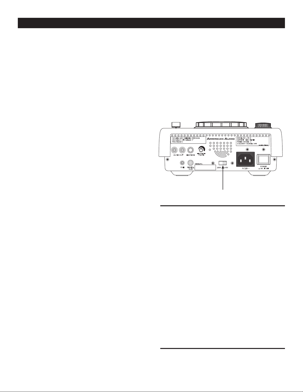
Line Voltage Selection
• The desired voltage may be set with the
VOLTAGE SELECTOR switch on the rear
panel (using a flat head screw driver).
• Do not force the VOLTAGE SELECTOR
switch as this may cause damage
• If the VOLTAGE SELECTOR switch does
not move smoothly, please contact a quali fied service technician.
VOLTAGE SELECTOR switch
The serial and model number for this unit
is located on the rear panel. Please write
down the numbers here and retain for future
reference.
Model No._____________________________
Serial No._____________________________
Purchase Notes:
Date of Purchase_______________________
Dealer Name__________________________
Dealer Address_________________________
_____________________________________
_____________________________________
________
Page 6

UNPACKING
Every PSX™ has been thoroughly tested and has been shipped in perfect operating condition. Carefully
check the shipping carton for damage that may have occurred during shipping. If the carton appears
to be damaged, carefully inspect your CD player for any damage and be sure all equipment necessary
to operate the CD player has arrived intact. In the event damage has been found or parts are missing,
please contact our toll free customer support number for further instructions. Please do not return the
CD player to your dealer without first contacting customer support.
INTRODUCTION
Introduction:
Congratulations and thank you for purchasing the American Audio® PSX™ CD player. This CD player
is a representation of American Audio’s continuing commitment to produce the best and highest quality audio products possible at an affordable price. Please read and understand this manual completely
before attempting to operate your new CD player. This booklet contains important information concerning the proper and safe operation of your new CD player.
Customer Support:
American Audio® provides a toll free customer support line, to provide set up help and answer any
question should you encounter problems during your initial set up or operation. You may also visit us
on the web at www.americanaudio.us for any comments or suggestions. Service Hours are Monday
through Friday 9:00 a.m. to 5:30 p.m. Pacific Standard Time.
Voice: (800) 322-6337
Fax: (323) 582-2610
E-mail: [email protected]
To purchase parts online visit http://parts.americandj.com
Caution! There are no user serviceable parts inside this CD player. Do not attempt any repairs yourself,
without being instructed to do so by an authorized American Audio service technician. Doing so will void
your manufactures warranty. In the unlikely event your CD player may require service, please contact
American Audio® customer support.
Do not discard the packing carton in the trash. Please recycle when ever possible.
SET-UP PRECAUTIONS
Please be sure to make any connections before plugging the CD player in to an electrical outlet. All
fader and volume controls should be set to zero or minimum position, before the CD player is switched
on. If the CD player has been exposed to drastic temperature fluctuation (e.g. after transportation), do
not switch on the CD player immediately. The arising condensation of water might damage your device.
Leave the device switched off until it has reached room temperature.
Operating Determinations:
• When installing this CD player, please make sure that the device is not exposed or will not be
exposed to extreme heat, moisture or dust!
• Do not operate the CD player in extremely hot (more than 30°/100°F) or extremely cold (less than
5°C/40°F) surroundings.
• Keep the unit out of direct sunlight and away from heaters.
• Operate the CD player only after becoming familiar with its' functions. Do not permit operation by
persons not qualified for operating the unit. Most damages are the result of unprofessional opera-
tion.
©American Audio® - www.americanaudio.us - PSX™ Instruction Manual Page 6
Page 7

MAIN FEATURES
• 8 times over sampling 1 bit D/A converter
• Auto cue
• 1/75th second frame search
• Real time cue (“Cue on the Fly”)
• 4 different speed scan (2 Forward/2 Reverse)
• Pitch display
• Digital RCA coaxial output
• Large bright Digital Screen can be viewed from wide angles.
• Fader “Q” Start Control (a)
• Seamless Loop (uninterrupted loop playback)
• Sampler (Forward & Reverse Sampling)
• Bop Effect (b)
• Flip-Flop (Relay Playback) (c)
• Adjustable Pitch Percentages: +/-8%, +/-12% or +/-16%
• Jog Wheel Pitch Bend +/-100%
• Memory Backup, Defaults to last setting (d)
• Instant Start within 10 ms (sound is produced immediately when the PLAY button is pressed)
• 3 Programmable Cue (Flash Start ) Buttons
• Slot Loading Drive - No more Transport Tray
• 384 programmable Cue Points (128 x 3) (e)
(a) FADER “Q” START CONTROL: This feature is used in conjunction with most American Audio® and American DJ®
audio mixers that also feature “Fader Q Start” control. For best results use this feature with two (2) PSX™ players.
Connect your PSX’s as described in the set-up section of this manual. After set-up is completed load your players.
By moving the mixer’s crossfader from left to right you can start and pause your PSX™ playback functions. For
Example, when using two (2) PSX™ players and a Fader “Q” Start mixer, if your mixer’s crossfader is all the way to
the left (player one is playing, player two is in cue or pause mode), and you move the fader at least 20% to the right,
player two (2) will begin to play and player one (1) will return to cue mode. When the crossfader is to the right, and
you move it 20% to the left, player one (1) will begin to play and player two (2) will return to its’ cue point. You can
create great effects similar to scratching with this feature. After storing cue points on each side of the CD player,
different songs or samples may quickly be recalled by moving the mixer crossfader back and forth. New cue points
can be easily selected on the PSX™ player (see setting cue points page 13). “Q” Start control is easy to use and
mastering this feature will help you create amazing effects with your music. Note: For proper “Q” Start operation be
sure your mixers “Hamster” setting are set to 1/2 (Normal Setting).
(b) BOP EFFECT: The Bop Effect button serves two features. First, it is a stutter effect, creating a sound similar to a
sampler. Second, it will return to the last Cue point in memory instantly. This will allow you to create great effects. To
create the BOP Effect, see BOP Effect on page 15.
(c) FLIP-FLOP: This feature is used in conjunction with American Audio® mixers that also feature Fader “Q” Start.
For FLIP-FLOP results you must use two (2) PSX™ players. Connect your PSX’s as described in the set-up
section of this manual. This feature will start the next player once one (1) player has ended. For example, if player
one (1) is playing a disc and it ends, player two (2) will instantly begin to play. You may set FLIP-FLOP to play track
to track or disc to disc. For more information on this feature, see FLIP-FLOP™ on page 18.
(d) MEMORY BACKUP: The PSX™ has a five (5) year memory back-up, that will save your setting in case the
power supply is accidentally disconnected. PSX™ will remember your last setting (repeat, SGL, CTN, and effect
parameters) even if you disconnect your main power. The PSX™ will store your cue points in memory
if you accidentally eject a disc or shut off the power. To store your settings into memory hold down the
BUTTON (7
) for 3 seconds. For more information see SYSTEM MEMORY on page 24.
MEMORY
(e) PROGRAMMABLE CUE POINTS: The PSX™ has three Flash Start Buttons (8). 128 Cue points can be stored in
each of the
memory and may be recalled at any time. See setting "Cue Points" on page 16
FLASH START BUTTONS (6), for a total of 384. These cue points can be stored into the unit's internal
©American Audio® - www.americanaudio.us - PSX™ Instruction Manual Page 7
Page 8
SET-UP
1. Checking the Contents
Be sure your PSX™ was shipped with the following:
1) PSX™ Professional CD player.
2) Operating instructions (this booklet).
3) One (1) set of RCA cables.
4) One (1) 1/8” mini plug.
5) Warranty card.
2. Installing the Units
Place your unit on a flat surface or mount it in a flat surface case
3. Connections
1) Be sure the power is disconnected.
2) Connect the included RCA cable from your PSX™ outputs to the inputs on your mixer.
3) Use the supplied 1/8” mini plug cable to connect your PSX™ to a mini jack connection (A or B ) on a compatible
American Audio® or American DJ® “Fader Q Start” mixer. (This will enable the Fader “Q” Start function - See
Fader “Q” start control page 8)
CAUTION:
• Be sure to use the supplied mono 1/8" control cables. Using other types of cable may result in unit damage
• To avoid sever damage to the unit, be sure the power is off when making connections to the unit.
CAUTION:
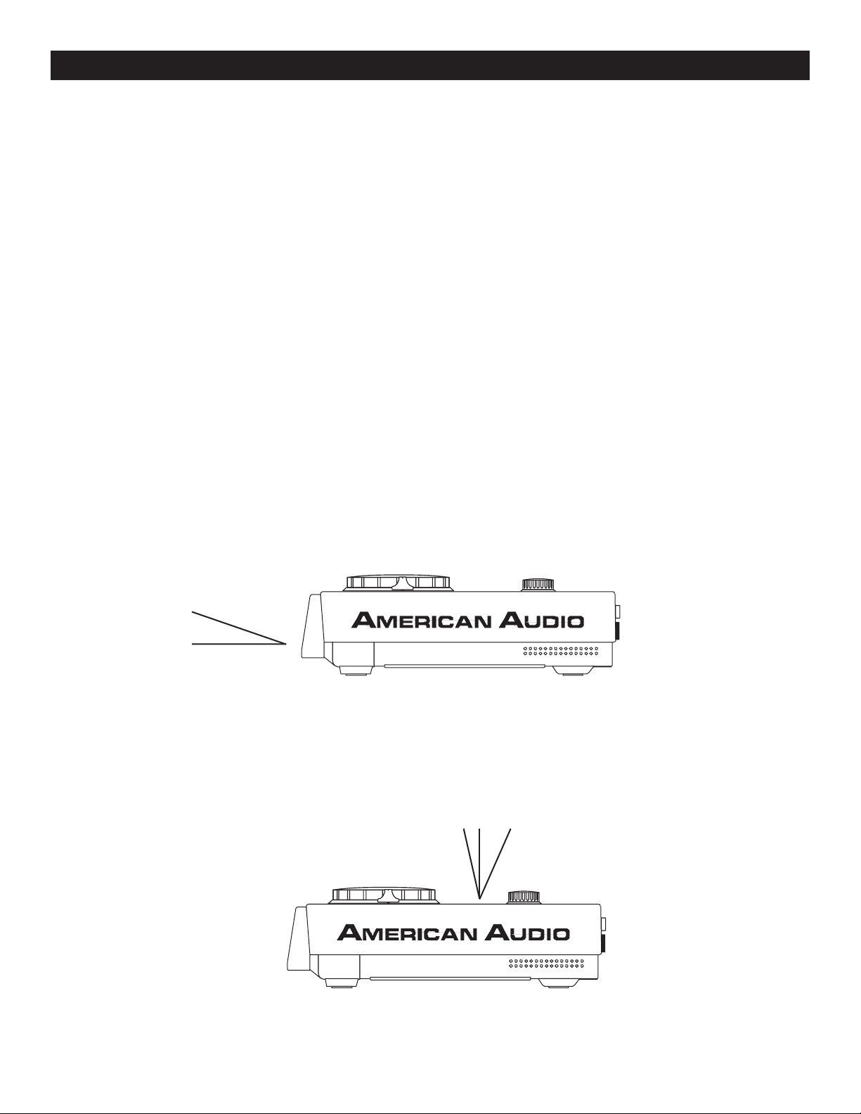
• The player will work normally when the main unit is mounted with the front panel within 15 degrees of
the vertical plane If the unit is tilted excessively, disks may not be loaded or unloaded properly. (Figure 1)
15˚
Figure 1
CAUTION:
• The LCD is designed to be clearly visible within the angles shown in Figure 2. Mount the control unit
so that the visual angle is within this range.
50˚10˚
Figure 2
©American Audio® - www.americanaudio.us - PSX™ Instruction Manual Page 8
Page 9
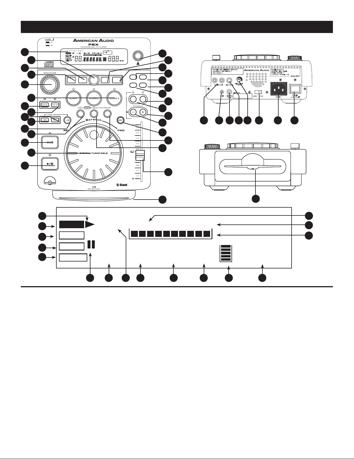
GENERAL FUNCTIONS AND CONTROLS
88
00
:
00 00
160
EFFECT
ELAPSED
SINGLE
TOTAL REMAIN
CUE
T M S F
LOOP
RELOOP
.
--
TRANSECH OSCRATC H FLAN GER
PARAME TER
SGL/CT
N
TIME AUT O
CUE
SAMPLE P ITCH
CUE
1 2 3 4 5 6 7 8 9 0
RELOO P
SINGL E
LOOP
REMAIN
TOTALELAPSE D
M
T
S
.
F
PITCH
CUE
AUTO
HOLD
EJECT/
STOP
8%/12%/16% ON/OF F
POWER
ON OFF
115V230V
DIGIT AL
OU
T
SERIAL NO :
CUE
HEADPH ONE
LR
HEADPHO NE
VOLUME
AUDIO O UT
Complies with DHHs radiation Perfomance
standards. 21 CFR Subchapter J"
Manufactured :
MODEL NO : PS X
COMPACT DISC PLAYER
POWER SOURCE :
115/230V~ 50/60Hz 14W
MADE IN TAIWAN
AC IN ~
Figure 3
1
2
3
4
5
6
7
8
9
10
11
12
13
14
15
31
30
29
28
27
26
25
24
23
22
21
20
19
18
17
37
3635343332 39
38
Figure 4
Figure 5
41
42
43
44
45
46
47
48
49
A. TOP UNIT CONTROLS (FIGURE 3)
1. LCD DISPLAY - This high quality LCD display
indicates all the functions, as they are occurring.
This display is viewable at several comfortable
angles (see page 4). The display ICONS will be
explained in the section D.
2. HOLD BUTTON - This button allows you to
set and lock any new parameters you set to
the effects. This button will glow bright blue
when the hold function is activated. If the hold
function is not selected any changes to the effect
parameters will be momentary.
3. FLANGER EFFECT - This button is used
to activate and deactivate the FLANGER effect.
See built-in effects on page 22.
©American Audio® - www.americanaudio.us - PSX™ Instruction Manual Page 9
16
40
56
55
54
50
51 52 53
Figure 6
4. SCRATCH BUTTON - This button is used to
activate and deactivate the Scratch effect. See
built-in effects on page 21.
5. SEARCH WHEEL - This wheel has four
forward and four reverse speed positions allowing
you to quickly scan through tracks. The more
you turn the wheel in either direction, the faster
your search.
6. FLASH BUTTONS 1-3 - These button are
used to store either three (3) cue points or three
(3) samples. Each Flash Button can store either
a sample or a cue point.
7. MEMORY BUTTON - This button allows you
to program up to 3 cue points or three samples in
to the three FLASH BUTTONS (6)
. The samples
Page 10

GENERAL FUNCTIONS AND CONTROLS (Cont.)
or cue point can then be recalled at any time even
when the disk has been removed and replaced at
a later time.
8. SAMPLER BUTTON - This is used to activate
the sampler function. When this function is acti
vated a created sample will play in a continuos
loop mode.
9. TRACK BUTTON - This buttons is
used to select a track. Tapping this button will
forward skip to the next track, holding down
this button will rapidly forward skip through the
tracks.
10. TRACK BUTTON - This buttons is
used to select a track. Tapping this button will
back skip on track, holding down this button will
rapidly BACK SKIP through the tracks.
11. + 10 - This button instantly advances the
track selection by 10. For example if the unit
is cued on track one, pressing this button will
instantly advance to and cue track 11. If the
button is pressed once more the unit will advance
to and cue track 21.
12. SEAMLESS LOOP IN BUTTON - “CUE ON
THE FLY” - This function allows you to set a
CUE POINT (see CUE POINT page 11) without
music interruption (“on the fly”). This button also
sets the starting point of a seamless loop (see
SEAMLESS LOOP).
13. CUE - Pressing the
CUE button during play-
back immediately pauses playback and returns
the track to the last set cue point (see setting a
CUE POINT, page 13). The red CUE LED will
glow when the unit is in cue mode The LED
will also flash every time a new CUE POINT
is set. The CUE button can be held down to
momentarily play the CD. When you release
the CUE button it instantly returns to the CUE
POINT. You can also tap the CUE button to
create a BOP EFFECT (for definition of BOP
EFFECT, see page 5).
14. JOG WHEEL - This wheel has two functions.
A. The jog wheel will act as a frame search
control when the CD is in pause or cue
mode, allowing you to set a cue point.
B. The wheel also works as a pitch bend during
©American Audio® - www.americanaudio.us - PSX™ Instruction Manual Page 10
playback. Turning the wheel clockwise will
increase the pitch percentage up to 100%, and
turning the wheel in the counter-clock- w i s e
direction will decrease the pitch percentage down
to -100%. The pitch bend will be determined on
how long you turn the jog wheel continuously.
15. PLAY/PAUSE BUTTON - Each press of the
PLAY/PAUSE BUTTON causes the operation to
change from play to pause or from pause to
play. While in play mode the green play LED will
glow, and while in pause mode the green play
LED will flash.
16. TRANSPORT SLOT - Trayless Design! A disc
is loaded the same as a car CD player, simply
insert the disc in to the slot and the unit will auto
matically load the disc in to the drive mechanism.
Never attempt to force a disc into the slot
when the power is turned off.
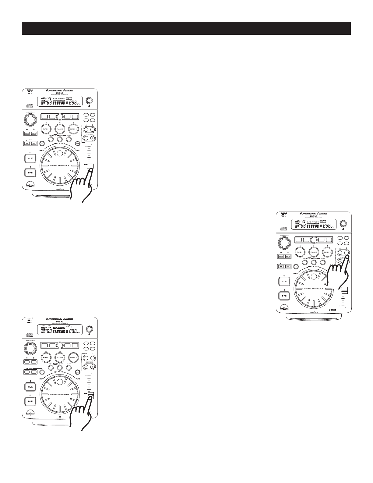
17. PITCH SLIDER - This slider is used to adjust
the playback pitch percentage. The slider is a set
adjustment and will remain set until the pitch slid
er is moved or the pitch function has been turned
off. This adjustment can be made with or with
out a disk in the drive. The pitch adjustment will
remain even if a disc has been remove and will
reflect on any other disc loaded into the player.
That is to say, if you set a +2% pitch on one disc,
remove that disc and insert another, that disc too
will have a +2% pitch. The amount of pitch being
applied will be displayed in the LCD (1).
18. OUT BUTTON
the ending point of a loop. A loop is started by
pressing the
BUTTON set the loop ending point. The loop
will continue to play until the OUT BUTTON
pressed once again.
19. RELOOP BUTTON - If a SEAMLESS LOOP
has been made (see setting a SEAMLESS LOOP
on page 11), but the CD Player is not actively in
SEAMLESS LOOP mode (a loop is not playing),
pressing the RELOOP BUTTON will instantly
reactivate the SEAMLESS LOOP mode. To exit
loop, press the OUT BUTTON (18)
RELOOP will appear in the LCD DISPLAY (1)
when the RELOOP function is available.
-
-
-
- This button is used to set
IN BUTTON (12), pressing the OUT
is
. LOOP and
Page 11

GENERAL FUNCTIONS AND CONTROLS (Cont.)
20. BOP - During play mode, pressing the BOP
button will instantly return play to the last set cue
point without interruption of music. Use this func
tion to create a stutter effect.
21. (-) PITCH BEND BUTTON - The (-) pitch bend
function creates a momentary “Slow Down” in the
CD’s BPM’s (Beats per minute) while it is playing.
This will allow you to match the beats between
two playing CD’s or other playing music source.
Remember, this is a momentary function. When
you remove your finger from the pitch button, the
BPM’s will automatically return to
ERS (17)
pitch value Holding down this button will
PITCH SLID-
give a maximum of +100% pitch. Use this func
tion to slow to another playing music source. Be
sure to notice that this function is a momentary
pitch adjustment, for a more precise adjustment
use the
PITCH SLIDER (17) to match the BPM’s
with another playing music source.
22. (+) PITCH BEND BUTTON - The (+) pitch
bend function creates a momentary “BUMP” in
the CD’s BPM’s (Beats per minute) while it is
playing. This will allow you to match the beats
between two playing CD’s or any other music
source. Remember, this is a momentary function.
When you remove your finger from this button,
the BPM’s will automatically return to PITCH
SLIDERS (17) selected pitch. Holding down this
button will give a maximum of +100% pitch.
23. PITCH PERCENTAGE BUTTON - This but
ton will change the pitch percentage the
SLIDER (17)
will react to. The pitch percentage
PITCH
can be changed between 8%, 12%, and 16%.
8% will allow the least amount of pitch manipula
tion and 16% will allow the most amount of pitch
manipulation. To adjust to the different values
tap this button at any time. The LED above the
PITCH PERCENTAGE BUTTON (23)
will indicate
which pitch percentage mode you are in, glowing
green for 8%, glowing orange for 12%, or glow
ing red for 16%. Note, the Pitch Function must be
activated (Pitch On/Off) to get a LED reading.
24. PITCH ON/OFF BUTTON - This button is
used to turn the PITCH SLIDER (17)
and off. The
PITCH BUTTON’s LED will indicate
©American Audio® - www.americanaudio.us - PSX™ Instruction Manual Page 11
function on
the pitch function has been activated.
25. TIME MODE - The TIME button will switch the
time value described in the TIME METER between
ELAPSED PLAYING TIME, TRACK
TIME, and TOTAL REMAINING TIME.
26. AUTO CUE FUNCTION - This button acti
vates the Auto Cue function. The Auto Cue
function allows the unit to automatically cue a
track when a CD is inserted, therefore allowing a
track to start instantly.
27. SGL/CTN - This function allows you to choose
between single track play or continuous track play
(all tracks in order). This function also operates in
PROGRAM
28. PARAMETERS - This button activates the
parameters mode. You use the parameters mode
to adjust and customize your effects settings.
29. TRANS EFFECT - This button is used to
activate and deactivate the TRANS effect. See
built-in effects on page 22.
30. ECHO EFFECT - This button is used to
activate and deactivate the ECHO effect. See
built-in effects on page 22.
31. EJECT/STOP FUNCTION - This button has
two functions. Pressing this button once will stop
CD playback, pressing this once more will eject
the CD. The CD may also be ejected while
the unit is in playback mode by pressing and
holding down this button for five seconds, this
is to prevent accidentally ejecting the disc when
in play mode.
-
B. REAR PANEL (FIGURE 4)
32. AUDIO OUT R & L - Audio out signals.
Connect stereo RCA cable from AUDIO OUT to
a mixer's line input.
33. CUE MINI JACK
plug from CUE jack on the rear of your unit to a
compatible American Audio® mixer’s CONTROL
out. This feature is only available on American
Audio’s “Q” series mixers.
34. DIGITAL OUT - Use this connection to create
near perfect copies of your disc to a Mini disc,
CD-R, or any other digital recording device.
REMAINING
-
and FLIP FLOP modes.
- Connect the supplied mini-
Page 12

GENERAL FUNCTIONS AND CONTROLS (Cont.)
35. HEADPHONE MONITOR - Use this stereo
jack to connect a pair of headphones.
36. HEADPHONE VOLUME CONTROL - This
knob will control the volume output level of the
HEADPHONE JACK (35).
37. VOLTAGE SELECTOR - Because power sup
plies vary from location to location we have
incorporated a selectable power supply. This
switch can select a voltage input of 115V or
230V. Always disconnect the power plug before
changing the voltage.
38. POWER CONNECTOR - This connection is
used to connect your main power. Be sure that
your local power matches the unit’s required
power.
39. POWER SWITCH - This switch is used to
turn your unit’s power on and off.
C. FRONT PANEL (FIGURE 5)
40. CD SLOT POWER INDICATOR - This is the
main power LED. This extremely bright Indigo
LED will also aid in locating the CD slot in dark
and club situations.
when the drive is in pause mode.
47. TRACK INDICATOR - This indicator describes
which track is currently cued or is playing.
48. CUE INDICATOR - This indicator will glow
when the unit is in CUE or mode and will flash
every time a new CUE POINT is set.
49, 50, 51. TIME METERS - These indicators will
detail the current Minutes, Seconds, and Frames.
The meter will display either the elapse, total, or
remaining time of a track or the entire disc. The
display time will depend on the selected time func
tion. The selected time function will be displayed
above the TIME METER
REMAIN (55) OR ELAPSE (56).
52. MEMORY BUCKET INDICATOR - This indi
cates serves two functions. The red bucket
outline details the cue memory status, a full
bucket outline indicates the cue memory is full.
The five bars in the memory bucket detail the
anti-shock memory state. Each bar indicates 2
second of digital anti-shock
53. PITCH METER - This meter will display either
the pitch percentage applied by the
ER (17)
.
-
as TOTAL REMAIN (55),
-
PITCH SLID-
D. LCD DISPLAY (FIGURE 6)
41. PLAY INDICATOR - This indicator will glow
when the unit is in play mode.
42. EFFECT INDICATOR - This will glow when
any of the four built-in effects are selected.
43. SINGLE INDICATOR - This indicates that the
CD drive is in single play mode, the track will
play once and return to CUE mode. If the single
indicator is not on the unit is in continuous mode
In continuous mode the drive will play all the
remaining tracks on the disc. Once the remaining
tracks have ended the unit will return to cue
mode
44. LOOP - This icon will flash when you are in
loop mode. This icon will glow when a loop has
been created but is not actively playing.
45. RELOOP INDICATOR - Appears when LOOP
is engaged or ready to be engaged.
46. PAUSE INDICATOR - This indicator will glow
54. TIME BAR INDICATOR - This bar gives a
visual approximation of a track's or disc's time
This bar will begin to flash when a track is
ending. The flashing bar is great reminder, that
time is running out to get that next track ready
to go.
55. TOTAL/REMAIN INDICATOR -
is indicated in the
DESCRIBED (49, 50, & 51)
the total disc remaining time.
is indicated in the
DESCRIBED (49, 50, & 51)
the current track's remaining time.
56. ELAPSE INDICATOR - When this indica
tor is on it will define the time displayed in the
TIME METER (49, 50, & 51)
elapse time.
LCD DISPLAY (1) the TIME
in the LCD will define
LCD DISPLAY (1) the TIME
in the LCD will define
as the current track’s
When TOTAL
When REMAIN
-
©American Audio® - www.americanaudio.us - PSX™ Instruction Manual Page 12
Page 13
BASIC OPERATIONS
TRANSECHOSCRATCH FLANGER
PARAMETE R
SGL/CT
N
TIME AUTO
CUE
SAMPLE PI TCH
CUE
1 2 3 4 5 6 7 8 9 0
RELOOP
SINGLE
LOOP
REMAIN
NONSTOP
TOTALELAPSED
M
T
S
PROGRA M
.
F
PITCH
BPM
CUE
AUTO
HOLD
EJECT/
STOP
8%/12%/16% ON/ OFF
TRANSECHOSCRATCH FLANGER
PARAMETER
SGL/CT
N
TIME AUTO
CUE
SAMPLE PITC H
CUE
1 2 3 4 5 6 7 8 9 0
RELOOP
SINGLE
LOOP
REMAIN
TOTALELAPSED
M
T
S
.
F
PITCH
CUE
AUTO
HOLD
EJECT/
STOP
8%/12%/16% ON/OFF
TRANSECHOSCRATCH FLANGER
PARAMETER
SGL/CT
N
TIME AUTO
CUE
SAMPLE PITC H
CUE
1 2 3 4 5 6 7 8 9 0
RELOOP
SINGLE
LOOP
REMAIN
TOTALELAPSED
M
T
S
.
F
PITCH
CUE
AUTO
HOLD
EJECT/
STOP
8%/12%/16% ON/OFF
TRANSECHOSCRATCH FLANGER
PARAMETER
SGL/CT
N
TIME AUTO
CUE
SAMPLE PITC H
CUE
1 2 3 4 5 6 7 8 9 0
RELOOP
SINGLE
LOOP
REMAIN
TOTALELAPSED
M
T
S
.
F
PITCH
CUE
AUTO
HOLD
EJECT/
STOP
8%/12%/16% ON/OFF
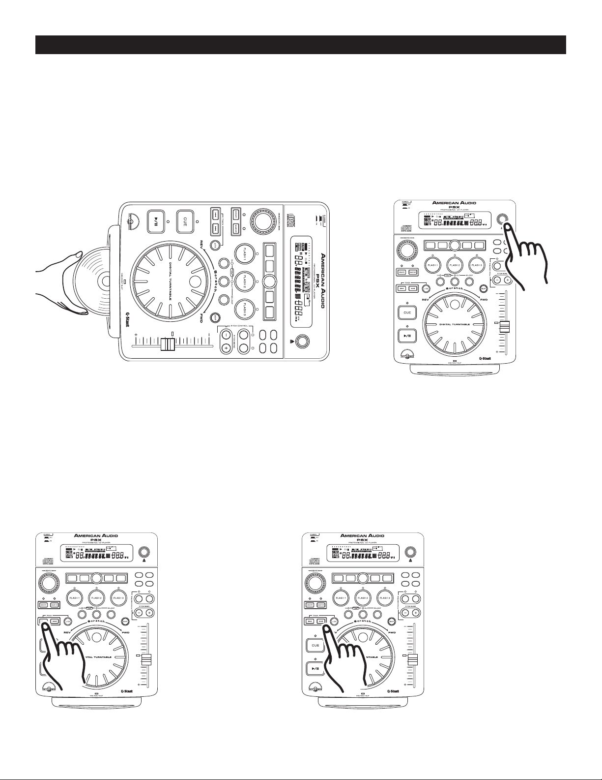
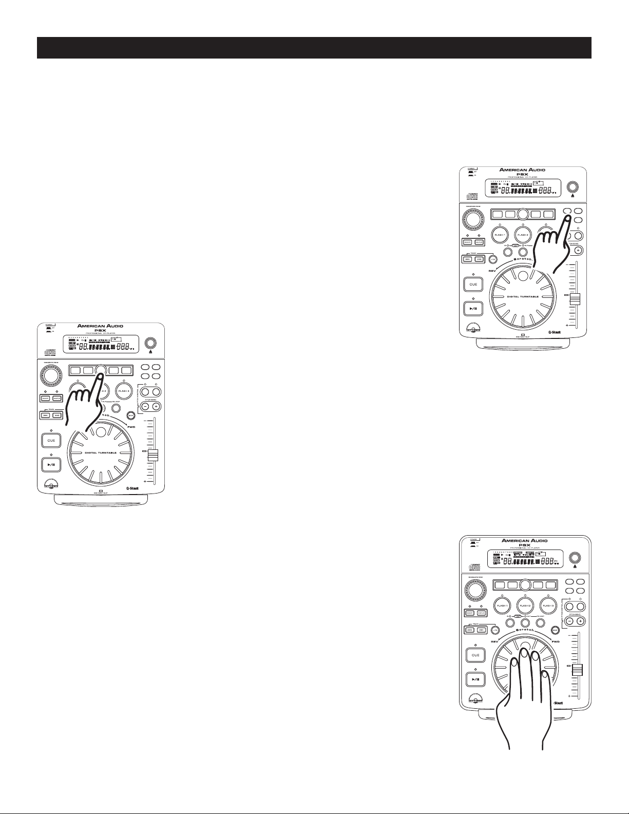
1. LOADING/EJECTING DISCS
The PSX™ can only play regular 5 inch CDs. 3 inch, odd shaped, and oval CDs are not compatible. When
loading a CD into the player always hold the disc by it edge (see Figure 7). Load the disc label side up and
slide it in the disc slot. Never touch the signal surface (the glossy side). To remove a disc from the slot press
the EJECT/STOP BUTTON (31), see Figure 8.
CAUTION:
NEVER attempt to insert any other objects beside 5" CD in the disc slot.
•
• NEVER attempt to insert more than one disc at a time. Doing so may result in sever damage to your unit.
• DO NOT force a disc into the slot when the power is off, this may damage the drive system.
Figure 7:
disc by it edges and load the disc label side up.
When inserting a disc always hold the
Figure 8
2. SELECTING TRACKS
Select a desired track by using either of the two TRACK BUTTONS (9 & 10). Tapping the TRACK BUTTONS
(9 & 10) once will select either the next higher or lower track. You may hold down the
10) to change tracks continuously at a faster speed. If you are using the TRACK BUTTONS (9 & 10) to select a
new track during playback (a track is already in play mode) the new track you selected will immediately begin
playback as soon as the search operation is completed.
Figure 9: When inserting a
disc always hold the disc by it
edges and load the disc label
side up.
©American Audio® - www.americanaudio.us - PSX™ Instruction Manual Page 13
TRACK BUTTONS (9 &
Figure 10: When inserting a
disc always hold the disc by it
edges and load the disc label
side up.
Page 14
BASIC OPERATIONS (CONT.)
TRANSECHOSCRATCH FLANGER
PARAMETER
SGL/CT
N
TIME AUTO
CUE
SAMPLE PITC H
CUE
1 2 3 4 5 6 7 8 9 0
RELOOP
SINGLE
LOOP
REMAIN
TOTALELAPSED
M
T
S
.
F
PITCH
CUE
AUTO
HOLD
EJECT/
STOP
8%/12%/16% ON/OFF
TRANSECHOSCRATCH FLANGER
PARAMETER
SGL/CT
N
TIME AUTO
CUE
SAMPLE PITC H
CUE
1 2 3 4 5 6 7 8 9 0
RELOOP
SINGLE
LOOP
REMAIN
TOTALELAPSED
M
T
S
.
F
PITCH
CUE
AUTO
HOLD
EJECT/
STOP
8%/12%/16% ON/OFF
TRANSECHOSCRATCH FLANGER
PARAMETER
SGL/CTN
TIME AUTO
CUE
SAMPLE PITC H
CUE
1 2 3 4 5 6 7 8 9 0
RELOOP
SINGLE
LOOP
REMAIN
NONSTOP
TOTALELAPSED
M
T
S
PROGRAM
.
F
PITCH
BPM
CUE
AUTO
HOLD
EJECT/
STOP
8%/12%/16% ON/OFF
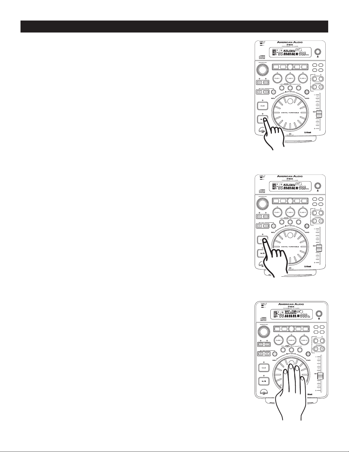
3. STARTING PLAYBACK - Figure 11
Insert an audio CD as describe on page 12 (LOADING/EJECTING DISCS).
Pressing the PLAY/PAUSE BUTTON (15) with an audio CD inserted will imme
diately start playback. The PLAY (41)
begins. The point at which playback starts (cue point) will automatically be stored
in the memory as the cue point. The unit will return to this cue point (the point at
which playback started) when the
pressed.
4. AUTO CUE
Press the AUTO CUE BUTTON (26) to engage the Auto Cue function. This function
will automatically set a cue point to the first audio source when a CD is inserted.
The first set cue point will always be the beginning of track 1. If a new track is
selected before the PLAY BUTTON (15) is pressed, a new CUE POINT will be set
to reflect the new starting point.
5. STOPPING PLAYBACK - Figures 11 & 12
Stopping playback will not stop the drive mechanism, but merely pause or cue the
track, this functions allows the unit to begin play instantly. The drive mechanism
will only stop if a disc is ejected or the unit has gone in to sleep mode. There are
two ways to stop (pause) playback:
1) Press the PLAY/PAUSE BUTTON (15) during playback. This will
pause playback at the exact same point the
pressed.
2) Press the
return the track to the last set cue point.
CUE BUTTON (13) during playback. This will pause playback and
indicator will glow as soon as playback
CUE BUTTON (13) or the BOP BUTTON (20) is
PLAY/PAUSE BUTTON (15) was
-
Figure 11
6. PAUSING - Figure 11
This function pauses playback at the exact same point the PLAY/PAUSE BUTTON
(15) was pressed. Pressing the PLAY/PAUSE BUTTON (15) will switch between
play and pause modes. When the unit is in pause mode the PAUSE INDICATOR
(46) in the LCD DISPLAY (1) will glow. The green PLAY/PAUSE BUTTON (15) LED
will also begin to flash repeatedly.
7. FRAME SEARCH
This feature allows you to scroll through a track frame by frame, allowing you to find
and set a starting cue, sample, or loop point. To use the scroll function you must
first be in Pause Mode (see section 5) or Cue Mode (see section 7). Once you are
in Pause or Cue mode, turn the
13). Turning the wheel in a clockwise direction will advance the frame search and
turning the wheel in a counter-clockwise direction rewinds the frame search. When
you use the JOG WHEEL (14)
to here what you are scrolling through. Once you reach your desired starting point
you can set a cue (starting) point by pressing the
in Figure 11. Pressing the
to the point you just set.
JOG WHEEL (14) to scroll through the track (Figure
the monitor (headphone level) function allows you
PLAY/PAUSE BUTTON (15) as
CUE BUTTON (10) as in Figure 12 will now return you
Figure 13
Figure 12
©American Audio® - www.americanaudio.us - PSX™ Instruction Manual Page 14
Page 15
BASIC OPERATIONS (CONT.)
TRANSECHOSCRATCH FLANGER
PARAMETER
SGL/CT
N
TIME AUTO
CUE
SAMPLE PIT CH
CUE
1 2 3 4 5 6 7 8 9 0
SINGLE
LOOP
REMAIN
NONSTOP
TOTALELAPSED
M
T
S
PROGRAM
.
F
PITCH
BPM
CUE
AUTO
HOLD
EJECT/
STOP
8%/12%/16% ON /OFF
RELOOP
TRANSECHOSCRATCH FLANGER
PARAMETER
SGL/CT
N
TIME AUTO
CUE
SAMPLE PITC H
CUE
1 2 3 4 5 6 7 8 9 0
RELOOP
SINGLE
LOOP
REMAIN
TOTALELAPSED
M
T
S
.
F
PITCH
CUE
AUTO
HOLD
EJECT/
STOP
8%/12%/16% ON/OFF
TRANSECHOSCRATCH FLANGER
PARAMETER
SGL/CTN
TIME AUTO
CUE
SAMPLE PITC H
CUE
1 2 3 4 5 6 7 8 9 0
RELOOP
SINGLE
LOOP
REMAIN
NONSTOP
TOTALELAPSED
M
T
S
PROGRAM
.
F
PITCH
BPM
CUE
AUTO
HOLD
EJECT/
STOP
8%/12%/16% ON/OFF
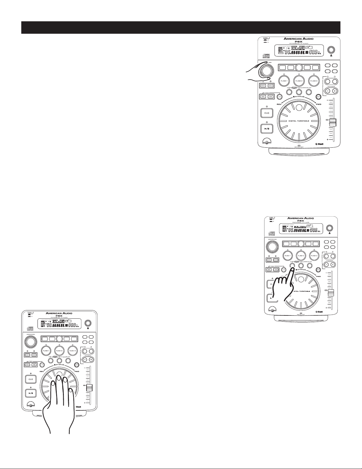
8. SCANNING (FAST FORWARD / FAST REVERSE)
This function gives you a fast search through a disk or track. Turn the
SEARCH WHEEL (5)
counterclockwise for fast reverse. You can scan in four different forward
and four different reverse speeds depending on how much you rotate the
wheel.
9. SETTING and STORING a CUE POINT:
Setting A Cue Point:
A cue point is the exact point playback will begin when the PLAY/PAUSE (15) is pressed. You may set your cue
points anywhere on a disc or in a track. You may set up to four independent cue points per disk. Three cue points
are stored in the
the CUE BUTTON (13). There are two (2) ways to set and create a CUE point as detailed in figures 15 and 16
Storing A Cue Point:
in clockwise direction for fast forward or turn the wheel
Figure 14
FLASH BUTTONS 1-3 (6) and one is shared by the IN BUTTON (12), BOP BUTTON (20) and
1) You may press the IN BUTTON (12) on the fly (while the disc is playing). This
will set a CUE Point without music interruption. Pressing the
(13)
BUTTON (12)
BUTTONS 1-3 (6).
the IN BUTTON (12)
will now return you to the same point that you pressed the IN
. You may now store this CUE Point in any of the FLASH
Pressing the CUE BUTTON (13), BOP BUTTON (20) or
will now return you to this exact point.
2) You may also use the
in PAUSE or CUE mode, use the JOG WHEEL (14)
find your desired starting point. Once you have found your desired position press
PLAY BUTTON (15) to set your cue point. Pressing the CUE BUTTON (13) or
the
the IN BUTTON (12) will now return you to this exact point.
Figure 16
JOG WHEEL (14) to set a cue point. While a disc is
CUE BUTTON
Figure 15
to scroll through a track to
©American Audio® - www.americanaudio.us - PSX™ Instruction Manual Page 15
Page 16
BASIC OPERATIONS (CONT.)
TRANSECHOSCRATCH FLAN GER
PARAMETER
SGL/CT
N
TIME AU TO
CUE
SAMPLE PITC H
CUE
1 2 3 4 5 6 7 8 9 0
RELOOP
SINGLE
LOOP
REMAIN
TOTALELAPSED
M
T
S
.
F
PITCH
CUE
AUTO
HOLD
EJECT/
STOP
8%/12%/16% ON/OFF
TRANSECHOSCRATCH FLAN GER
PARAMETER
SGL/CT
N
TIME AU TO
CUE
SAMPLE PITC H
CUE
1 2 3 4 5 6 7 8 9 0
RELOOP
SINGLE
LOOP
REMAIN
TOTALELAPSED
M
T
S
.
F
PITCH
CUE
AUTO
HOLD
EJECT/
STOP
8%/12%/16% ON/OFF
TRANSECHOSCRATCH FLANGER
PARAMETER
SGL/CT
N
TIME AUTO
CUE
SAMPLE PITC H
CUE
1 2 3 4 5 6 7 8 9 0
RELOOP
SINGLE
LOOP
REMAIN
TOTALELAPSED
M
T
S
.
F
PITCH
CUE
AUTO
HOLD
EJECT/
STOP
8%/12%/16% ON/OFF
TRANSECHOSCRATCH FLANGER
PARAMETER
SGL/CT
N
TIME AUTO
CUE
SAMPLE PITC H
CUE
1 2 3 4 5 6 7 8 9 0
RELOOP
SINGLE
LOOP
REMAIN
TOTALELAPSED
M
T
S
.
F
PITCH
CUE
AUTO
HOLD
EJECT/
STOP
8%/12%/16% ON/OFF
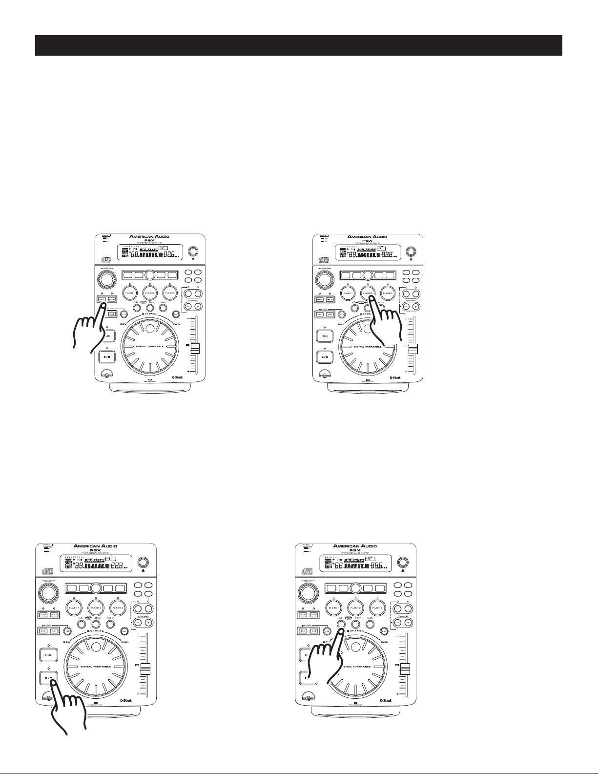
Once you have set your CUE Point by one of the two means listed on page 14, you may store your cue point in
one of the
may even recall if the disc has been remove or power had been disconnected. You may store a maximum of
three cue points per a disc and maximum of 384 cue points can saved in unit's memory. The
ET (52)
(See creating a sample loop on page 17) can be stored into a
point:
FLASH BUTTONS (6). Once you store this cue point in memory you may recall it at any time and you
MEMORY BUCK-
in the LCD DISPLAY (1) will approximate the available memory. Either a CUE POINT or a SAMPLE
FLASH BUTTON (6), not both. To Store a cue
1) Create a Cue Point by one of the two means listed on page 14. Press the
MEMORY BUTTON (12), as
in Figure 17. The red Memory Cue LED will glow indicating the store memory function has been activated.
You may now press any one of the three
18). After pressing one of the
FLASH BUTTONS (6), the corresponding Flash Button LED will flash briefly.
FLASH BUTTONS (6) to store your cue point into memory (Figure
The LED on the above the Flash Button (6) will remain lit indicating either a sample or cue point is stored
in memory. The red Memory LED will turn off.
Figure 17
Figure 18
2) Repeat the above steps to store up to three Cue Points. Once all your three cue points have been stored you
may access them at any time. During playback the cue points will instantly start playback from that point without
any music interruption. Please note in order to access these cue point, the disc used to create the cue points
must be in the drive.
10. CREATING AND PLAYING A SEAMLESS LOOP
A seamless loop is a sound loop that plays continuously without sound interruption. You can use this loop to
create dramatic effect in your mixing. This loop has no time limit and you could actually loop the entire length
of disc. You create a seamless loop between two continuous points of a disc.
11. EDITING A LOOP:
1) Press
BUTTON (15) to
activate playback
mode
Figure 19
©American Audio® - www.americanaudio.us - PSX™ Instruction Manual Page 16
PLAY/PAUSE
2) Press the IN BUTTON
(12)
. This will set the
starting point of the
SEAMLESS LOOP. The
IN BUTTON (12) LED
will light.
Figure 20
Page 17
BASIC OPERATIONS (CONT.)
TRANSECHOSCRATCH FLANGER
PARAMETER
SGL/CT
N
TIME AUTO
CUE
SAMPLE PITC H
CUE
1 2 3 4 5 6 7 8 9 0
RELOOP
SINGLE
LOOP
REMAIN
TOTALELAPSED
M
T
S
.
F
PITCH
CUE
AUTO
HOLD
EJECT/
STOP
8%/12%/16% ON/OFF
TRANSECHOSCRATCH FLANGER
PARAMETER
SGL/CT
N
TIME AUTO
CUE
SAMPLE PITC H
CUE
1 2 3 4 5 6 7 8 9 0
RELOOP
SINGLE
LOOP
REMAIN
TOTALELAPSED
M
T
S
.
F
PITCH
CUE
AUTO
HOLD
EJECT/
STOP
8%/12%/16% ON/OFF
TRANSECHOSCRATCH FLANGER
PARAMETER
SGL/CT
N
TIME AUTO
CUE
SAMPLE PITC H
CUE
1 2 3 4 5 6 7 8 9 0
RELOOP
SINGLE
LOOP
REMAIN
TOTALELAPSED
M
T
S
.
F
PITCH
CUE
AUTO
HOLD
EJECT/
STOP
8%/12%/16% ON/OFF
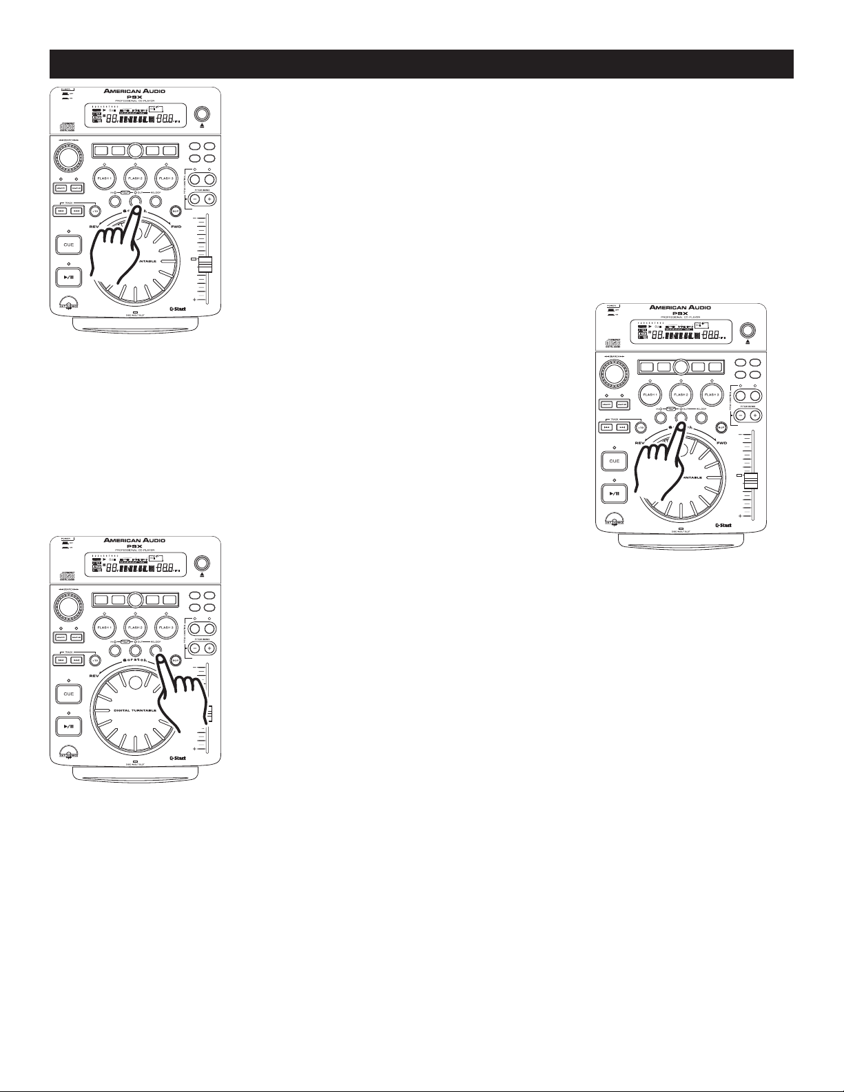
3) Press the OUT BUTTON (18) to set the ending point for your SEAMLESS
LOOP (Figure 13). The
immediately begin to flash rapidly, indicating the SEAMLESS LOOP mode
has been activated.
LCD LOOP INDICATORS - During a seamless loop, the LOOP (44) and
RELOOP (45) INDICATORS
is active.
Figure 21
EXITING A LOOP - To exit a SEAMLESS LOOP, press the OUT
BUTTON (18)
remain on, but will stop flashing. Music playback will resume normal
play (Figure 13). The IN BUTTON (12)
will remain on to remind you that a loop is stored in memory.
. The IN BUTTON (12) and OUT BUTTON (18) LEDs will
and OUT BUTTON (18) LEDs
IN BUTTON (12) and OUT BUTTON (18) LEDs will
will turn on in the LCD DISPLAY (1) indication a loop
Figure 22
REPLAY LOOP - The RELOOP (19) function allows you to return to your stored
loop at any time. The
a loop is stored in memory, and may be played at any time. To replay the loop,
press the
RELOOP BUTTON (19). The IN BUTTON (12) and OUT BUTTON (18)
LEDs will again begin to flash indicating SEAMLESS LOOP mode has been acti
vated (Figure 14) and your stored loop will immediately begin to play.
Figure 23
Please note: Only the ending point of the loop may be edited. You may make your loop shorter or longer. Before
you can edit your seamless loop you obviously must first have created a seamless loop to edit. If you haven’t
created a SEAMLESS LOOP, follow the instructions in step 10 to create a loop. If a SEAMLESS LOOP has
already been created, press the RELOOP BUTTON (19) to activate your SEAMLESS LOOP (Figure 23) if it is
not already activated. To edit your seamless loop’s ending point:
1) Press the
OUT BUTTON (18) to return to normal play from the loops cue point. (Figure 20). This will
disengage the SEAMLESS LOOP mode and allows you to edit the loops ending point.
2) Press the
- FOR A SHORTER LOOP: Press the
- FOR LONGER LOOP: Press the
OUT BUTTON (18) again when you reach your new ending point (Figure 21).
OUT BUTTON (18) at sooner point in the track (Figure 21).
OUT BUTTON (14) at later point in the track (Figure 21).
IN BUTTON (12) and OUT BUTTON (18) LEDs will indicate
12. Using the Built In Sampler:
©American Audio® - www.americanaudio.us - PSX™ Instruction Manual Page 17
-
Page 18
BASIC OPERATIONS (CONT.)
TRANSECHOSCRATCH FLANGER
PARAMETER
SGL/CT
N
TIME AUTO
CUE
SAMPLE PITC H
CUE
1 2 3 4 5 6 7 8 9 0
RELOOP
SINGLE
LOOP
REMAIN
TOTALELAPSED
M
T
S
.
F
PITCH
CUE
AUTO
HOLD
EJECT/
STOP
8%/12%/16% ON/OFF
TRANSECHOSCRATCH FLANGER
PARAMETER
SGL/CT
N
TIME AUTO
CUE
SAMPLE PITC H
CUE
1 2 3 4 5 6 7 8 9 0
RELOOP
SINGLE
LOOP
REMAIN
TOTALELAPSED
M
T
S
.
F
PITCH
CUE
AUTO
HOLD
EJECT/
STOP
8%/12%/16% ON/OFF
TRANSECHOSCRATCH FLANGER
PARAMETER
SGL/CT
N
TIME AUTO
CUE
SAMPLE PITC H
CUE
1 2 3 4 5 6 7 8 9 0
RELOOP
SINGLE
LOOP
REMAIN
TOTALELAPSED
M
T
S
.
F
PITCH
CUE
AUTO
HOLD
EJECT/
STOP
8%/12%/16% ON/OFF
TRANSECHOSCRATCH FLANGER
PARAMETER
SGL/CT
N
TIME AUTO
CUE
SAMPLE PITC H
CUE
1 2 3 4 5 6 7 8 9 0
RELOOP
SINGLE
LOOP
REMAIN
TOTALELAPSED
M
T
S
.
F
PITCH
CUE
AUTO
HOLD
EJECT/
STOP
8%/12%/16% ON/OFF
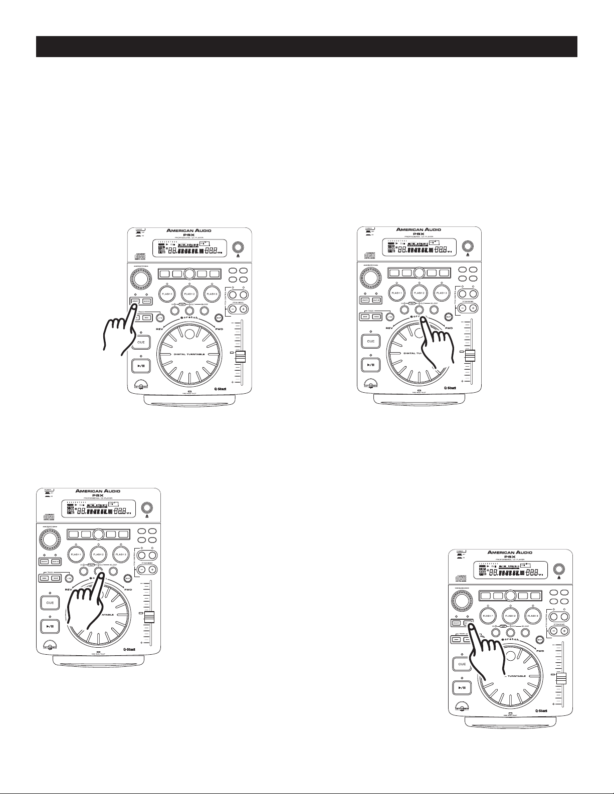
Your PSX™ comes with a built in sampler. You may store up to three samples on the three FLASH BUTTON (6)
(Once again please note you may only store either a CUE POINT or a SAMPLE into a
both). Your sample can be a maximum of 7 seconds in length. A sample can be recalled while a CD is playing, or
while the CD drive is in PAUSE MODE. You may play your sample at anytime without music interruption. If you
play your sample when the unit is already in playback mode you sample will over lap the current music source.
You can also play your sample once or in a continuous loop. As with cue points you may store approximately
384 (128 x 3) samples in a drives memory (depending on available memory). The
the LCD DISPLAY (1) will approximate the remaining memory.
To create a sample:
1) Initialize a loop (see creating a seamless loop on page 15). If your loop is longer than 6.5 seconds it
can not be stored as a sample and will stored as a Cue Point.
FLASH BUTTON (6), not
MEMORY BUCKET (52) on
2) Press the MEMORY BUTTON (7). The
MEMORY CUE BUTTON (1) Red LED will
glow indicating memory is ready to be stored.
3) Select one of the three FLASH BUTTON
(6) you wish to store your loop in and press
that button.
4) The red MEMORY BUTTON (7) LED will turn off, when your sample is locked
into memory.
5) At this point your sample has been stored into memory. The original loop you
used to create the sample will remain playing until the OUT BUTTON (18) is
pressed (Figure 26).
6) Your sample can now be recalled at any time
even when the unit is in PAUSE MODE. To recall
the sample
be sure the sample function is on, by
pressing the SAMPLE BUTTON (8) until the red sam
ple button LED turn
Figure 26
Important Notice: If you try to activate your sample without turning
continuos loop leave the sample function on. To play
your sample just once, turn the sample function off
immediately after initiating your sample. With the
sample function on the sample will continue to play
until the sample function is turned off.
the sample function on, the Flash button (6) will act as cue points!
s on. To play your sample in a
Figure 27
Figure 25Figure 24
-
©American Audio® - www.americanaudio.us - PSX™ Instruction Manual Page 18
Page 19
BASIC OPERATIONS (CONT.)
TRANSECHOSCRATCH FLANGER
PARAMETER
SGL/CT
N
TIME AUTO
CUE
SAMPLE PITC H
CUE
1 2 3 4 5 6 7 8 9 0
RELOOP
SINGLE
LOOP
REMAIN
TOTALELAPSED
M
T
S
.
F
PITCH
CUE
AUTO
HOLD
EJECT/
STOP
8%/12%/16% ON/OFF
TRANSECHOSCRATCH FLANGER
PARAMETER
SGL/CT
N
TIME AUTO
CUE
SAMPLE PITC H
CUE
1 2 3 4 5 6 7 8 9 0
RELOOP
SINGLE
LOOP
REMAIN
TOTALELAPSED
M
T
S
.
F
PITCH
CUE
AUTO
HOLD
EJECT/
STOP
8%/12%/16% ON/OFF
TRANSECHOSCRATCH FLANGER
PARAMETER
SGL/CTN
TIME AUTO
CUE
SAMPLE PITC H
CUE
1 2 3 4 5 6 7 8 9 0
RELOOP
SINGLE
LOOP
REMAIN
NONSTOP
TOTALELAPSED
M
T
S
PROGRAM
.
F
PITCH
BPM
CUE
AUTO
HOLD
EJECT/
STOP
8%/12%/16% ON/OFF
Changing the Sample Parameters:
Changing the sample parameters allows you to change the sample's volume and pitch. The param
eters values for both the pitch and volume settings range from 00:00 to 20:00, 00:00 being the lowest
value. A higher value will increase the pitch percentage or volume. It's important to understand that the
pitch value is basic a speed adjustment and has nothing to do tonal quality. The values can be either
a momentary change or set adjustment. The sample values are changed in three easy steps, while in
sample playback mode:
Changing the Sample Parameters - Step 1:
While a sample is playing tap the PARAMETERS BUTTON (28). One tap
will display
BUTTON (28)
signify the pitch percentage and
is your default setting - Normal playback. Any adjustments will be based on
this default setting.
SP 10 00 in the LCD DISPLAY (1). If you tap the PARAMETERS
again, SV 10 00 will read out in the LCD DISPLAY (1). SP will
SV will signify the sample volume. 10 00
Figure 28
-
Changing the Sample Parameters - Step 2:
Hold Function - This mode will allow you to save and lock your parameter
adjustments, if the hold function is not activated all your parameter adjust
ments will be momentary. Once you are in the parameters mode you can
begin to make your adjustments.
Figure 29
Changing the Sample Parameters - Step 3:
Use the JOG WHEEL (14) to change your selected parameters. Turning the
wheel in a clockwise rotation will increase your parameters - this will wither
increase the volume or increase the pitch. Turning the wheel in a counterclockwise direction will decrease the parameters value, either decreasing
the volume or decreasing the pitch. If you engaged the HOLD BUTTON (2)
in the previous step, you would now turn the hold function off to save your
settings.
-
Figure 30
©American Audio® - www.americanaudio.us - PSX™ Instruction Manual Page 19
Page 20
BASIC OPERATIONS (CONT.)
TRANSECHOSCRATCH FLANGER
PARAMETER
SGL/CT
N
TIME AUTO
CUE
SAMPLE PITC H
CUE
1 2 3 4 5 6 7 8 9 0
RELOOP
SINGLE
LOOP
REMAIN
TOTALELAPSED
M
T
S
.
F
PITCH
CUE
AUTO
HOLD
EJECT/
STOP
8%/12%/16% ON/OFF
TRANSECHOSCRATCH FLANGER
PARAMETER
SGL/CT
N
TIME AUTO
CUE
SAMPLE PITC H
CUE
1 2 3 4 5 6 7 8 9 0
RELOOP
SINGLE
LOOP
REMAIN
TOTALELAPSED
M
T
S
.
F
PITCH
CUE
AUTO
HOLD
EJECT/
STOP
8%/12%/16% ON/OFF
TRANSECHOSCRATCH FLANGER
PARAMETER
SGL/CT
N
TIME AUTO
CUE
SAMPLE PITC H
CUE
1 2 3 4 5 6 7 8 9 0
RELOOP
SINGLE
LOOP
REMAIN
TOTALELAPSED
M
T
S
.
F
PITCH
CUE
AUTO
HOLD
EJECT/
STOP
8%/12%/16% ON/OFF
TRANSECHOSCRATCH FLANGER
PARAMETER
SGL/CT
N
TIME AUTO
CUE
SAMPLE PITC H
CUE
1 2 3 4 5 6 7 8 9 0
RELOOP
SINGLE
LOOP
REMAIN
TOTALELAPSED
M
T
S
.
F
PITCH
CUE
AUTO
HOLD
EJECT/
STOP
8%/12%/16% ON/OFF
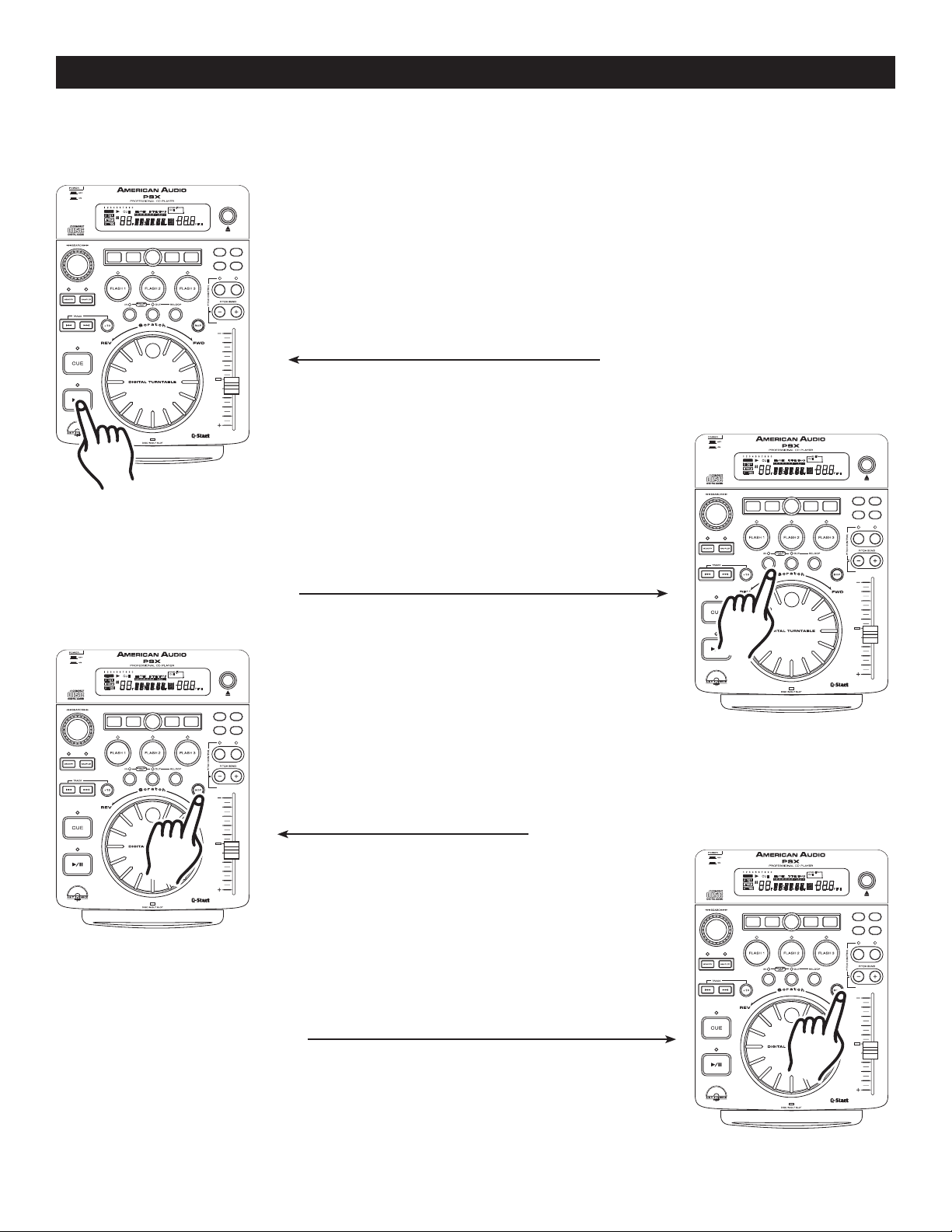
13. Creating a BOP Effect:
The Bop Effect is a stutter effect that is similar to turntable scratching. You can use this effect to create tricks
in your mixing. Creating a BOP effect is a simple process:
1) Press the PLAY/PAUSE BUTTON
(15)
Figure 31
so music is playing (Figure 31).
2) Press the
IN BUTTON (12) (Figure 32) at
the point you want your BOP to take place.
Figure 32
3) Now tap the
a stutter effect as quickly as you tap on the
BUTTON (20)
Figure 33
4) When you discontinue the BOP effect normal playback
will resume from the point you initial started your BOP.
BOP BUTTON (20). It will produce
BOP
. See Figure 34.
Figure 34
©American Audio® - www.americanaudio.us - PSX™ Instruction Manual Page 20
Page 21
BASIC OPERATIONS (CONT.)
TRANSECHOSCRATCH FLANGER
PARAMETER
SGL/CT
N
TIME AUTO
CUE
SAMPLE PITC H
CUE
1 2 3 4 5 6 7 8 9 0
RELOOP
SINGLE
LOOP
REMAIN
TOTALELAPSED
M
T
S
.
F
PITCH
CUE
AUTO
HOLD
EJECT/
STOP
8%/12%/16% ON/OFF
TRANSECHOSCRATCH FLANGER
PARAMETER
SGL/CT
N
TIME AUTO
CUE
SAMPLE PITC H
CUE
1 2 3 4 5 6 7 8 9 0
RELOOP
SINGLE
LOOP
REMAIN
TOTALELAPSED
M
T
S
.
F
PITCH
CUE
AUTO
HOLD
EJECT/
STOP
8%/12%/16% ON/OFF
88
00
:
00 00
160
EFFECT
ELAPSED
SINGLE
TOTAL REMAIN
CUE
T M S F
LOOP
RELOOP
.
--
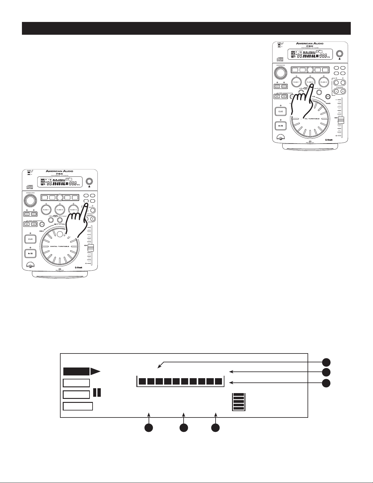
14. FLASH START BUTTONS (6):
These button are used to store your samples and cue points. Only a sample
or a cue point can be stored into each of these three banks. When a sample is
stored in to these banks you may use the sample starting point as a cue point.
The FLASH BUTTONS instantly recall and play any of your stored samples or
cue points without interrupting music playback. When in sample mode, (see
"Using the Built-In Sampler" on page 17) and during playback, pressing any of
the FLASH BUTTONS (6) that stores a sample, will immediately begin to play that
sample without interruption of music. If the unit is in sample mode and the drive
is not in playback mode, pressing any of the
sample, will immediately begin to play that sample.
15. CHANGING THE TIME DISPLAY (49, 50, & 51)/TIME BAR (54):
DURING NORMAL PLAYBACK, pressing the TIME BUTTON (25), will change the
time display information (49, 50, 51, 55, & 57) in the LCD (1) see figure 35. The
following is a break down of the time settings and their definitions:
FLASH BUTTONS (6) that stores a
Figure 35
1) ELAPSED (56) - This describes the time in the LCD (49, 50, & 51) as the
current TRACKS Elapse running time.
2) REMAIN (55) - This describes the time in the LCD (49, 50, & 51) as the
current TRACKS remaining running time.
3) TOTAL REMAIN (55) - This describes the time in the LCD (49, 50, & 51) as
the disc total remaining running time.
Figure 36
TIME BAR INDICATOR
- Details the time defined in the TIME METER (49, 50, & 51) as a visual bar icon. As
with the TIME METER (49, 50, & 51) this bar is also dependent on the selected time function [TOTAL REMAIN
(55), REMAIN (55) OR ELAPSE (56)]
. This bar will begin to flash when a track is ending regardless of which time
function you are in. Use the flashing bar as a visual reminder that a track is ending.
56
55
54
©American Audio® - www.americanaudio.us - PSX™ Instruction Manual Page 21
49
50
51
Figure 37
Page 22
PITCH ADJUSTMENTS
TRANSECHOSCRATCH FLANGER
PARAMETER
SGL/CT
N
TIME AUTO
CUE
SAMPLE PITC H
CUE
1 2 3 4 5 6 7 8 9 0
RELOOP
SINGLE
LOOP
REMAIN
TOTALELAPSED
M
T
S
.
F
PITCH
CUE
AUTO
HOLD
EJECT/
STOP
8%/12%/16% ON/OFF
TRANSECHOSCRATCH FLANGER
PARAMETER
SGL/CT
N
TIME AUTO
CUE
SAMPLE PITC H
CUE
1 2 3 4 5 6 7 8 9 0
RELOOP
SINGLE
LOOP
REMAIN
TOTALELAPSED
M
T
S
.
F
PITCH
CUE
AUTO
HOLD
EJECT/
STOP
8%/12%/16% ON/OFF
TRANSECHOSCRATCH FLANGER
PARAMETER
SGL/CT
N
TIME AUTO
CUE
SAMPLE PITC H
CUE
1 2 3 4 5 6 7 8 9 0
RELOOP
SINGLE
LOOP
REMAIN
TOTALELAPSED
M
T
S
.
F
PITCH
CUE
AUTO
HOLD
EJECT/
STOP
8%/12%/16% ON/OFF
PITCH ADJUSTMENTS:
The different pitch adjustments allow a track's or a loop's playback speed to be manipulated. This speed manipulations is commonly used to beat match between two or more music sources such as a turntable or another CD
played. The playback speed may be increased or decreased by a factor of +/-100. The next section details the
different pitch manipulation schemes.
1. PITCH SLIDER:
This function will increase or decrease the tracks playback speed or "PITCH." The
maximum pitch percentage manipulation in this function is +/-16%. The
SLIDER (17)
move up (towards the top of the unit) the pitch will decrease, if the slider is moved
down (towards the bottom of the unit) the pitch will increase. The PITCH SLIDER
(17) adjustment can be changed to range from +/-8%, +/-12%, or +/-16% (See
changing "PITCH SLIDER PERCENTAGE RANGE" on the next page). This pitch
adjustments will effect normal playback and loops only when the Pitch On/Off
Button (24) is turned on. The pitch adjustments will not effect your samples.
PITCH
is used to decrease or increase the playback pitch. If the slider is
Figure 38
Activating the Pitch Slider (17): To activate the PITCH SLIDER (17) you
must turn on the pitch adjustment function. Press the
located in the pitch control section of the unit. The ON/OFF BUTTON (24)
will glow when the function is activated. If the pitch function is not activated the
PITCH SLIDER (17)
will not function.
ON/OFF BUTTON (24)
LED
Figure 39
Using the Pitch Slider (17): Be sure the pitch function has been engaged
as described above. To use the pitch slider (17) slide the slider up and down.
Down will increase the pitch and up will decrease the pitch. When the slider
is in the center position, a green LED just left of the slider will glow. When this
slider is glowing there is zero pitch being applied to the track, regardless if the
pitch function is on or off.
Figure 40
©American Audio® - www.americanaudio.us - PSX™ Instruction Manual Page 22
Page 23
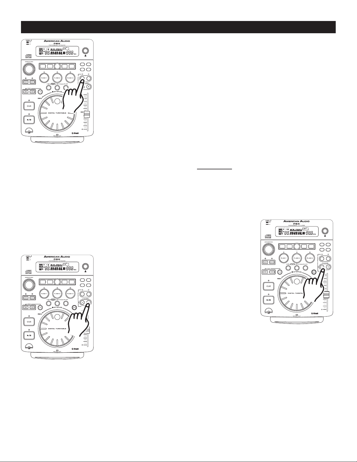
PITCH ADJUSTMENTS
TRANSECHOSCRATCH FLANGER
PARAMETER
SGL/CT
N
TIME AUTO
CUE
SAMPLE PITC H
CUE
1 2 3 4 5 6 7 8 9 0
RELOOP
SINGLE
LOOP
REMAIN
TOTALELAPSED
M
T
S
.
F
PITCH
CUE
AUTO
HOLD
EJECT/
STOP
8%/12%/16% ON/OFF
TRANSECHOSCRATCH FLANGER
PARAMETER
SGL/CT
N
TIME AUTO
CUE
SAMPLE PITC H
CUE
1 2 3 4 5 6 7 8 9 0
RELOOP
SINGLE
LOOP
REMAIN
TOTALELAPSED
M
T
S
.
F
PITCH
CUE
AUTO
HOLD
EJECT/
STOP
8%/12%/16% ON/OFF
TRANSECHOSCRATCH FLANGER
PARAMETER
SGL/CT
N
TIME AUTO
CUE
SAMPLE PITC H
CUE
1 2 3 4 5 6 7 8 9 0
RELOOP
SINGLE
LOOP
REMAIN
TOTALELAPSED
M
T
S
.
F
PITCH
CUE
AUTO
HOLD
EJECT/
STOP
8%/12%/16% ON/OFF
Figure 41
2. PITCH BENDING:
Adjusting the Pitch Slider's Range (17): You may change the pitch slider's
(17) operating range. To change the operating range be sure the pitch function
is turned on, see figure 39.
The pitch percentage can be changed between +/8%, +/-12%, and +/-16%. 8% will allow the least amount of pitch manipulation
and 16% will allow the most amount of pitch manipulation. To adjust to the dif
ferent values tap the 8% 12% 16% BUTTON (23). The LED above the
PERCENTAGE BUTTON (23)
will indicate which pitch percentage mode you are
PITCH
in by, glowing green for 8%, glowing orange for 12%, or glowing red for 16%.
Note, the pitch percentage must be activated to get a LED reading.
-
Unlike the
during playback. There are two ways to operate this function with the (-) & (+) PITCH BUTTONS (21 & 22)
PITCH SLIDER (17) adjustment this function will momentarily increase or decrease a tracks speed
or with
the JOG WHEEL (14). The maximum pitch bend percentage allowed is +/- 100%. The pitch bend function will
work in conjunction with the
2% pitch gain the pitch bending process will begin at 2% and wi
PITCH SLIDER (17) pitch setting. For example, if the PITCH SLIDER (17) is set to a
ll continue to the maximum of +/- 100%.
NOTE: A -100% pitch manipulation will stop playback entirely.
Holding down or tapping on the
PITCH BEND BUTTON
(21) will provide
a slow down in the playback pitch
Holding down or tapping on the (+)
PITCH BEND BUTTON
(22) will provide
a speed bump in the playback pitch.
Figure 42
(-)
.
PITCH BEND BUTTONS (21 & 22):
The (+) PITCH BEND BUTTON (22) will increase track playback speed and the (-) PITCH BEND BUTTON (21)
Figure 42
will decrease track playback speed. The extent to which the speed changes is proportionate to the amount of
time the button is pressed. For example, if the (+) PITCH BEND BUTTON (22)
figure 43, the disc speed will increases and will continue to increase until reaches a maximum of 100% speed
gain. When you release the (+) PITCH BEND BUTTON (22)
the disc speed will automatically return to it’s previ-
is held down continuously as in
ous set speed.
©American Audio® - www.americanaudio.us - PSX™ Instruction Manual Page 23
Page 24
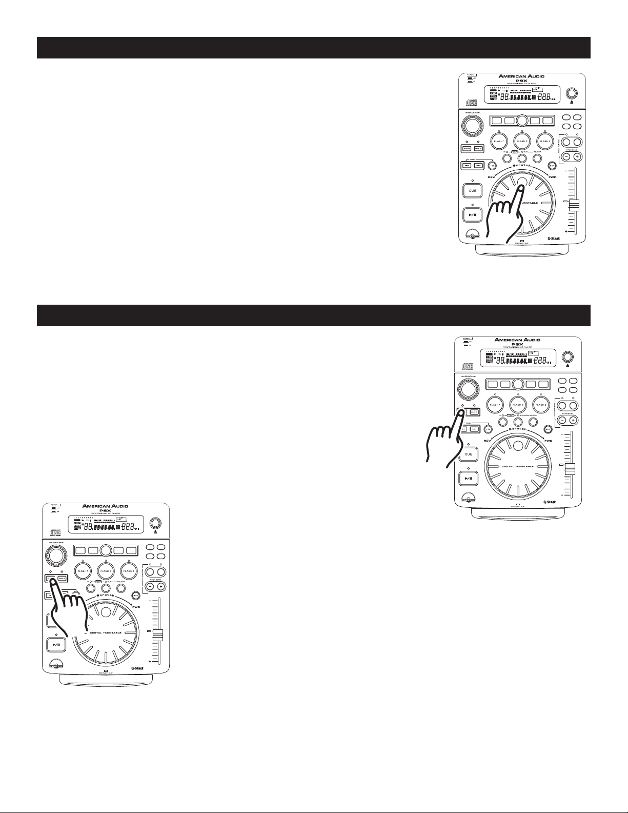
PITCH ADJUSTMENTS
TRANSECHOSCRATCH FLANGER
PARAMETER
SGL/CT
N
TIME AUTO
CUE
SAMPLE PITC H
CUE
1 2 3 4 5 6 7 8 9 0
RELOOP
SINGLE
LOOP
REMAIN
TOTALELAPSED
M
T
S
.
F
PITCH
CUE
AUTO
HOLD
EJECT/
STOP
8%/12%/16% ON/OFF
TRANSECHOSCRATCH FLANGER
PARAMETER
SGL/CT
N
TIME AUTO
CUE
SAMPLE PITC H
CUE
1 2 3 4 5 6 7 8 9 0
RELOOP
SINGLE
LOOP
REMAIN
TOTALELAPSED
M
T
S
.
F
PITCH
CUE
AUTO
HOLD
EJECT/
STOP
8%/12%/16% ON/OFF
TRANSECHOSCRATCH FLANGER
PARAMETER
SGL/CT
N
TIME AUTO
CUE
SAMPLE PITC H
CUE
1 2 3 4 5 6 7 8 9 0
RELOOP
SINGLE
LOOP
REMAIN
TOTALELAPSED
M
T
S
.
F
PITCH
CUE
AUTO
HOLD
EJECT/
STOP
8%/12%/16% ON/OFF
JOG WHEEL (14):
The JOG WHEEL will temporarily bend the pitch if a track is in playback mode
Rotating the wheel in a clockwise direction will increase your track pitch and
rotating the wheel in a counter-clockwise direction will slow your track pitch.
The speed you rotate the
(%). For example, if the
wise direction the playback speed will steadily decreases and will continue to
decrease until playback reaches a maximum of -100% and playback stops
entirely. When you stop turning the
cally return to it’s previous set speed.
JOG WHEEL will determine pitch bend percentage
JOG WHEEL is continuously turned in a counter-clock-
JOG WHEEL the disc speed will automati-
Figure 44
SYSTEM MEMORY
SYSTEM MEMORY:
The PSX™ comes with an incredible memory system. The PSX™ can memorize
virtually every customized setting for a particular CD. The unit can memorize all
customized effect parameters, cue points, and samples used on a particular disk.
To store all your setting for a CD, press and hold down the MEMORY BUT
-
TON (16) for at least three seconds. When the memory has been stored
properly the MEMORY LED (16) will turn off. The memory is full the RED
outline of the MEMORY BUCKET (39) in the LCD (30) will disappear.
Figure 45
RECALL FLASH MEMORY:
The PSX™ can store all your user programmed cue points and effect parameters
in to memory. These setting may be recalled at any time, even when a disc has
been removed and reinserted at a later time. To recall the memory on a specific
disc; 1) Be sure a CD is not inserted in to the drive. 2) Press the MEMORY BUT
TON (16) down until the red memory LED turns on. 3) Insert the CD. "RECALL"
will appear in the LCD (30) while the memory is being installed and the red
MEMORY BUTTON (16) led will turn off.
Figure
46
-
©American Audio® - www.americanaudio.us - PSX™ Instruction Manual Page 24
Page 25
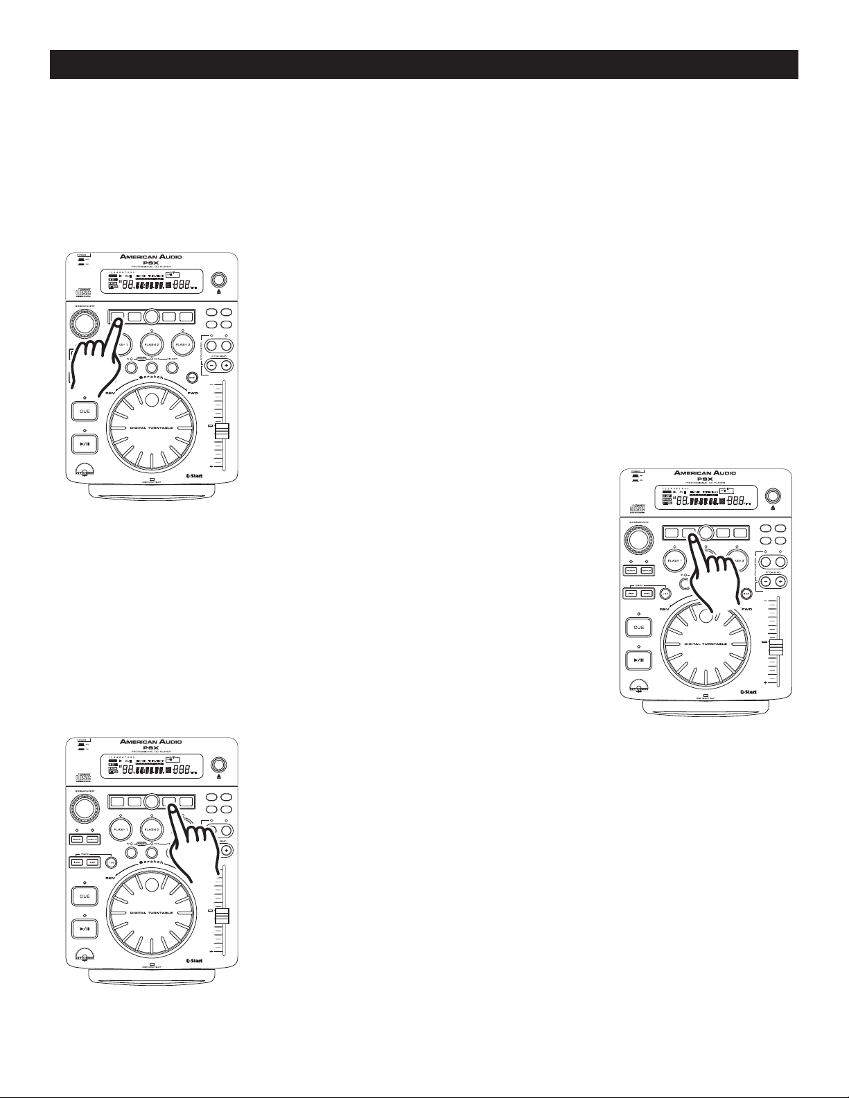
BUILT-IN EFFECTS
TRANSECHOSCRATCH FLANGER
PARAMETER
SGL/CT
N
TIME AUTO
CUE
SAMPLE PITC H
CUE
1 2 3 4 5 6 7 8 9 0
RELOOP
SINGLE
LOOP
REMAIN
TOTALELAPSED
M
T
S
.
F
PITCH
CUE
AUTO
HOLD
EJECT/
STOP
8%/12%/16% ON/OFF
TRANSECHOSCRATCH FLANGER
PARAMETER
SGL/CT
N
TIME AUTO
CUE
SAMPLE PITC H
CUE
1 2 3 4 5 6 7 8 9 0
RELOOP
SINGLE
LOOP
REMAIN
TOTALELAPSED
M
T
S
.
F
PITCH
CUE
AUTO
HOLD
EJECT/
STOP
8%/12%/16% ON/OFF
TRANSECHOSCRATCH FLANGER
PARAMETER
SGL/CT
N
TIME AUTO
CUE
SAMPLE PITC H
CUE
1 2 3 4 5 6 7 8 9 0
RELOOP
SINGLE
LOOP
REMAIN
TOTALELAPSED
M
T
S
.
F
PITCH
CUE
AUTO
HOLD
EJECT/
STOP
8%/12%/16% ON/OFF
The PSX™ comes with five built in effects. These effects can be used one at a time or you may choose to
overlap the effects and use up to four at a time. The Built-in effects include Scratch, Flanger, Echo, Robot, and
Transform. Up to four effects may run at the same time. When any of the effects are activated, the EFFECT (42)
icon will display in the LCD (1). You can choose to use the effects with their default setting or you may choose
to customized each effect by changing the parameters.
Some effects will have more adjustable parameters than others. The parameters have two adjustable values,
PR (Parameter Ratio) and PV (Parameter volume).
All parameters will be reset to there default values when
power is shut off!
SCRATCH EFFECT: The Scratch effect simulates real time turntable scratch-
ing. Pressing
When the Scratch Effect is activated the SCRATCH BUTTON (4)
the Scratch Effect has been activated the JOG WHEEL (14) may be used in the
same fashion a turntable platter is used. Use the JOG WHEEL (14) to simulate
the scratch motion on a turntable platter and to manipulate playback.
SCRATCH BUTTON (4) will activate the scratch effect (figure 45).
The parameters values for all the effects will range.
will glow. Once
Figure 47
FLANGER EFFECT: The flanger effect distorts the output signal and cre-
ates an effect similar to frequencies phasing in and out of each other.
FLANGER Effect has two adjustable parameters, Parameter Time (PT) and
Parameter Ratio (PR). The PT will adjust the Flanger Mode and The PR will
adjust the Flanger Frequency Range (see "Parameters" in the next section).
The
Figure 48
ECHO EFFECT: The ECHO effect adds an echo to your output signal. The
ECHO Effect has two adjustable parameters, Parameter Time (PT) and Parameter
Ratio (PR). The PR will adjust the length of the echo (drop off time), and the PT
will adjust the echo gap length (see "Parameters" in the next section).
ROBOT EFFECT: The ROBOT effect distorts the output to simulates a sci-
fi robot voice. The ROBOT effect is activated in the ECHO parameters
"Parameters" in the next section). To activate the ROBOT effect select the ECHO
effect. After the Echo effect is activated enter the Parameters menu and turn the
HOLD (2) function on. Set the (PT) value to 0010. After "PT" value has been set,
tap the PARAMETER BUTTON (28) again to enter into "PR" values menu. Now
use turn the JOG WHEEL (14) back and forth to create the effect.
(see
Figure 49
©American Audio® - www.americanaudio.us - PSX™ Instruction Manual Page 25
Page 26
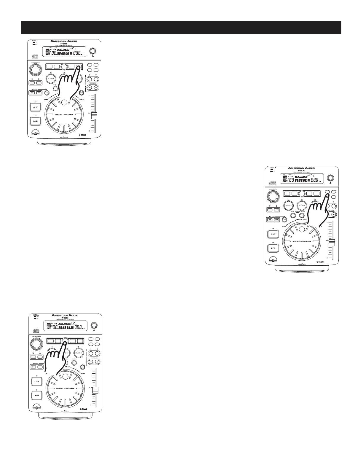
BUILT-IN EFFECTS
TRANSECHOSCRATCH FLANGER
PARAMETER
SGL/CT
N
TIME AUTO
CUE
SAMPLE PITC H
CUE
1 2 3 4 5 6 7 8 9 0
RELOOP
SINGLE
LOOP
REMAIN
TOTALELAPSED
M
T
S
.
F
PITCH
CUE
AUTO
HOLD
EJECT/
STOP
8%/12%/16% ON/OFF
TRANSECHOSCRATCH FLANGER
PARAMETER
SGL/CT
N
TIME AUTO
CUE
SAMPLE PITC H
CUE
1 2 3 4 5 6 7 8 9 0
RELOOP
SINGLE
LOOP
REMAIN
TOTALELAPSED
M
T
S
.
F
PITCH
CUE
AUTO
HOLD
EJECT/
STOP
8%/12%/16% ON/OFF
TRANSECHOSCRATCH FLANGER
PARAMETER
SGL/CT
N
TIME AUTO
CUE
SAMPLE PITC H
CUE
1 2 3 4 5 6 7 8 9 0
RELOOP
SINGLE
LOOP
REMAIN
TOTALELAPSED
M
T
S
.
F
PITCH
CUE
AUTO
HOLD
EJECT/
STOP
8%/12%/16% ON/OFF
TRANS EFFECT: The TRANS effect simulates a real-time mixer transformer
effect. Pressing TRANS BUTTON (29)
ure 48). When the "Transformer" effect is activated the
glow.
TRANS EFFECT: The TRANS Effect has two adjustable parameters, Parameter
Time and Parameter Ratio. The PT will adjust the Trans Speed and The PR will
adjust the Trans Audio Length. The lower the PT value the faster the TRANS effect
(PT 0500 = 1/2 second, PT 1000 = 1 second).
Figure 50
PARAMETERS:
Most the effects have adjustable parameters. The parameters change the way the
effect will react. To enter the parameters menu for any of the effects, press the
PARAMETER BUTTON (28)
the time display in the LCD (1) will change to indicate the parameters. Some
effects have more adjustable parameter than others. Pressing the PARAMETER
BUTTON (28)
more than once will advance you to the next parameter adjustment,
if there are no other adjustable parameters pressing the PARAMETER BUTTON
(28) will exit the parameters menu and return the LCD (1) to the time display.
as in figure 49. When the parameter mode is selected
will activate the "Transformer" effect (fig-
TRANS BUTTON (29) will
Figure 51
HOLD BUTTON: Use the HOLD BUTTON (2) to lock your customized param-
eters. If the hold button is not activated any changes to your parameters will
be momentary. To activate the hold function press the HOLD BUTTON (2) as in
©American Audio® - www.americanaudio.us - PSX™ Instruction Manual Page 26
figure 52. When the hold function becomes activated, the hold button will begin
to glow blue.
Figure 52
Page 27
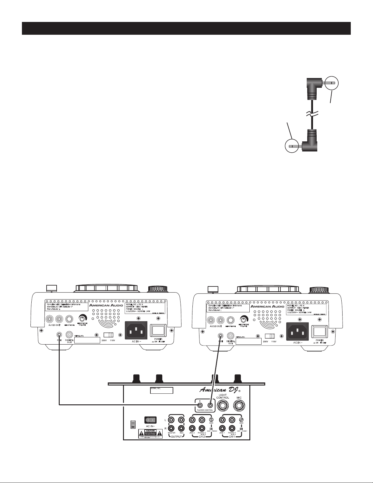
FLIP -FLOP™
POWE R
ON OFF
115V230 V
DIGI TAL
OU
T
SERIA L NO:
CUE
HEADP HONE
LR
HEADP HONE
VOLUM E
AUDI O OUT
Complies with DHHs radiation Perfomance
standards. 21 CFR Subchapter J"
Manufactured :
MODEL NO : PS X
COMPACT DISC PLAYER
POWER SOURCE :
115/230V~ 50/60Hz 14W
MADE IN TAIWAN
AC IN ~
POWE R
ON OFF
115V230 V
DIGI TAL
OU
T
SERIA L NO:
CUE
HEADP HONE
LR
HEADP HONE
VOLUM E
AUDI O OUT
Complies with DHHs radiation Perfomance
standards. 21 CFR Subchapter J"
Manufactured :
MODEL NO : PS X
COMPACT DISC PLAYER
POWER SOURCE :
115/230V~ 50/60Hz 14W
MADE IN TAIWAN
AC IN ~
FLIP-FLOP™
This feature is kind of “auto pilot”. When you are using two PSX™ players and an American Audio® “Q” Deck™
mixer, you can have one player begin playback when the other ends. You can “Flip -Flop™” single tracks, the
entire disc, or a combination of the two.
FLIP-FLOP™ single tracks:
To
1) Connect your system as described in the set up section on page 7.
2) Set your American Audio® “Q” Deck™ mixer’s crossfader to the center
position.
3) Set your two PSX™ to playback in single mode, SINGLE (43) should be
indicated in the LCD (1).
4) Load your two PSX™ with audio disc.
5) After they have both cued, press the PLAY/PAUSE BUTTON (15
your drive to begin playback.
6) After the first player’s single track has ended the second player’s track will
immediately begin playback.
7) FLIP-FLOP™ will continue until you stop it or power is interrupted.
To Flip-Flop entire CDs:
Be sure your drives are both in continuous play mode, make sure SINGLE MODE (43)
LCD'S (1)
of both players. Follow all directions for single track FLIP -FLOP™ above. When one player’s disc
ends the other player will immediately begin playback.
Single black cross line
Single black cross line
) on one of
Mono Mini Plug
does not appear in the
Note: You may combine FLIP -FLOP™ single and continuously playback modes by selecting either single or
continuous playback on your units.
Connecting your PSX™ to an American Audio® or an American DJ® “Q” Deck™ mixer for “Flip Flop™” control:
Be sure to connect 1/8” mono mini plugs from the control connection on the rear your PSX™ to the 1/8” control
jack on the rear of American Audio® “Q” series mixer. That’s it, you’ll be set for FLIP-FLOP.™
Sample "Q" Start Set-Up. This set-up will allow "Q" start functions and Flip-Flop™ function to operate.
Be sure to use 1/8" mono mini plugs only.
PSX 1 PSX 1
©American Audio® - www.americanaudio.us - PSX™ Instruction Manual Page 27
Compatible Q-Deck Mixer
Page 28

WARRANTY
WARRANTY INFORMATION:
The PSX™ carries a TWO year (730 days) limited warranty. This warranty covers parts and labor.
Please fill out the enclosed warranty card to validate your purchase and warranty. All returned service
items whether under warranty or not, must be freight pre-paid and accompany a return authorization
(R.A.) number. If the unit is under warranty, you must provide a copy of your proof of purchase invoice.
Please contact American Audio® customer support at (800) 322-6337 for a R.A. number. All package
not displaying a R.A. number on the outside of the package will be returned to the shipper.
2-YEAR LIMITED WARRANTY
A. American Audio® hereby warrants, to the original purchaser, American Audio® products to be free
of manufacturing defects in material and workmanship for a period of 2 Year (730 days) from the date
of purchase. This warranty shall be valid only if the product is purchased within the United States of
America, including possessions and territories. It is the owner’s responsibility to establish the date and
place of purchase by acceptable evidence, at the time service is sought.
B. For warranty service, send the product only to the American Audio
® factory. All shipping charges
must be pre-paid. If the requested repairs or service (including parts replacement) are within the terms
of this warranty, American Audio® will pay return shipping charges only to a designated point within the
United States. If the entire instrument is sent, it must be shipped in its original package. No accessories
should be shipped with the product. If any accessories are shipped with the product, American Audio®
shall have no liability whatsoever for loss of or damage to any such accessories, nor for the safe return
thereof.
C. This warranty is void if the serial number has been altered or removed; if the product is modified
in any manner which American Audio
® concludes, after inspection, affects the reliability of the product;
if the product has been repaired or serviced by anyone other than the American Audio® factory unless
prior written authorization was issued to purchaser by American Audio®; if the product is damaged
because not properly maintained as set forth in the instruction manual.
D. This is not a service contract, and this warranty does not include maintenance, cleaning or peri
odic check-up. During the period specified above, American Audio® will replace defective parts at its
expense, and will absorb all expenses for warranty service and repair labor by reason of defects in
material or workmanship. The sole responsibility of American Audio® under this warranty shall be limited to the repair of the product, or replacement thereof, including parts, at the sole discretion of American Audio®. All products covered by this warranty were manufactured after January 1, 1990, and bear
identifying marks to that effect.
E. American Audio
® reserves the right to make changes in design and/or improvements upon its prod-
ucts without any obligation to include these changes in any products theretofore manufactured.
-
F. No warranty, whether expressed or implied, is given or made with respect to any accessory supplied
with products described above. Except to the extent prohibited by applicable law, all implied warran
ties made by American Audio® in connection with this product, including warranties of merchantability
or fitness, are limited in duration to the warranty period set forth above. And no warranties, whether
expressed or implied, including warranties of merchantability or fitness, shall apply to this product after
said period has expired. The consumer’s and or Dealer’s sole remedy shall be such repair or replacement as is expressly provided above; and under no circumstances shall American Audio® be liable for
any loss or damage, direct or consequential, arising out of the use of, or inability to use, this product.
G. This warranty is the only written warranty applicable to American Audio® Products and supersedes
©American Audio® - www.americanaudio.us - PSX™ Instruction Manual Page 28
-
Page 29

NOTES
©American Audio® - www.americanaudio.us - PSX™ Instruction Manual Page 29
Page 30

NOTES
©American Audio® - www.americanaudio.us - PSX™ Instruction Manual Page 30
Page 31

SPECIFICATIONS
GENERAL Model: American Audio® PSX™ - Professional Compact Disc Player
Type: Slot loading, digital compact disc audio player.
Disc type: Standard size compact discs only (5 in / 12 cm discs)
Dimensions: 3 1/4” ~ 4 1/2” H x 8 1/2” W x 10 3/8” L (217.5 mm x 81.8 mm x 306 mm)
Installation: Place on flat surface or mount in flat case
Weight: 4 1/2 Lbs. / 1 3/4 Kgs
Power supply: AC 115/230V, 50/60Hz
Power consumption: 14W
Environmental conditions: Operational temperature: 5 to 35˚C (41 to 95˚F)
Operational humidity: 25 to 85% (no condensation)
Storage temperature: -20 to 60˚C (4 to 140˚F)
Accessories: Connecting RCA Cable (2 sets for left and right channels)
Control 1/8” miniplug type (3 feet)
AUDIO SECTION
Quantization: 16 bit linear per channel
Sampling rate: 44.1 kHz at normal pitch
Over sampling rate: 8 times
D/A conversion 16 bit
Frequency response: +/- 1 dB 20 Hz to 20,000 KHz
Output level: 2.0V +/- 1dB
Load impedance: 47k ohm or more
AUDIO CHARACTERISTICS (TEST DISC: TCD-782, LOAD=47Kohm)
ITEM NOMINAL LIMIT CONDITION
Output level 2.0Vrms+/-1dB 2.0V+/-1dB 1KHz,0dB
Channel balance 0.5dB 1.0dB 1KHz,0dB
Frequency response +/-0.5dB +/-1.0dB 20Hz-20KHz,0dB
De-emphasis response +/-2.5dB +/-3dB 16KHz, -20dB
Channel separation* 82dB 75dB 1KHz,0dB
T.H.D. + NOISE* 0.02% 0.025% 1KHz,0dB
S/N ratio (IHF-A)* 84dB 75dB 1KHz.0dB
Phones max. output 10mW 8mW 1KHz,THD=10%
NOTE: * With 20KHz low pass filter.
SEARCHING TIME (TEST DISC: TCD-792)
ITEM NOMINAL LIMITS CONDITION
Short access time 1.7sec 4sec Play next track
Long access time 3sec 6sec Track 1 ->Track 20
Track 20 ->Track 1
PLAYABILITY
ITEM NOMINAL LIMIT CONDITION
Interruption 1000um 700um TCD-725
Black dot 1000um 600um TCD-725
Finger prints 75um 65um TCD-725
Eccentricity 210um 140um TCD-712,713 NO TRACK JUMP
Vertical deviation 1mm 0.54mm TCD-731R
PICK-UP
System Object lens drive system optical pick-up
Object lens drive system 2 dimensional parallel drive
Tracking detection 3 spot beam detection
Optical source Semiconductor laser
Wave length 780nm
NOTES:
The specifications are subject to change to any improvement by negotiations in advance.
The parts are subject to change to any improvement within the range of the specifications.
©American Audio® - www.americanaudio.us - PSX™ Instruction Manual Page 31
Page 32

©American Audio® World Headquarters:
4295 Charter Street Los Angeles, CA 90058 USA
Tel: 323-582-3322 Fax: 323-582-3311
Web: www.americanaudio.us E-mail: [email protected]
 Loading...