

Page 1
WIFLY NE1 BATTERY
BATTERY
©2016 ADJ Products, LLC all rights reserved. Information,
specications, diagrams, images, and instructions herein are
subject to change without notice. ADJ Products, LLC logo and
identifying product names and numbers herein are trademarks
of ADJ Products, LLC. Copyright protection claimed includes all
forms and matters of copyrightable materials and information
now allowed by statutory or judicial law or hereinafter granted.
Product names used in this document may be trademarks or
registered trademarks of their respective companies and are
hereby acknowledged. All non-ADJ Products, LLC brands and
product names are trademarks or registered trademarks of their
respective companies.
ADJ Products, LLC and all aliated companies hereby dis-
claim any and all liabilities for property, equipment, building,
and electrical damages, injuries to any persons, and direct or
indirect economic loss associated with the use or reliance of
any information contained within this document, and/or as a
result of the improper, unsafe, unsucient and negligent assembly, installation, rigging, and operation of this product.
Rev. 5/16
User Instructions
Europe Energy Saving Notice
Energy Saving Matters (EuP 2009/125/EC)
Saving electric energy is a key to help protecting the enviroment.
Please turn o all electrical products when they are not in use. To
avoid power consumption in idle mode, disconnect all electrical
equipment from power when not in use. Thank you!
Page 2

WiFly NE1 Battery General Information
WiFly NE1 Battery General Instructions
Unpacking: Thank you for purchasing the WiFly NE1 Battery by ADJ
Products, LLC. Every WiFly NE1 Battery has been thoroughly tested
and has been shipped in perfect operating condition. Carefully check
the shipping carton for damage that may have occurred during shipping. If the carton appears to be damaged, carefully inspect your xture for any damage and be sure all equipment necessary to operate
the unit has arrived intact. In the event damage has been found or parts
are missing, please contact our toll free customer support number for
further instructions. Please do not return this unit to your dealer with-
out contacting customer support rst.
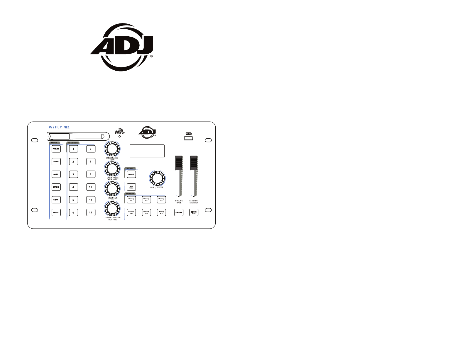
Introduction:
The WiFly NE1 Battery is a 432 channel battery pow-
ered DMX controller with ADJ’s WiFly, wireless DMX built-in or hard
wired via 3-pin DMX cable. This controller is designed for RGB, RGBW,
RGBA, RGBWA, and RGBWA + UV LED units. The controller come
preloaded with generic profiles for most of the fixture’s that fall into the
category above.
Customer Support: ADJ Products, LLC provides a toll free customer
support line, to provide help and to answer any question should you
encounter problems during your set up or initial operation. You may
also visit us on the web at www.adj.com for any comments or sugges-
tions. Service Hours are Monday through Friday 8:00 a.m. to 4:30 p.m.
Pacic Standard Time.
Voice: (800) 322-6337
Fax: (323) 582-2941
E-mail: support@americandj.com
Warning! To prevent or reduce the risk of electrical shock or re, do
not expose this unit to rain or moisture.
To optimize the performance of this product, please read these
operating instructions carefully to familiarize yourself with the basic
operations of this unit. These instructions contain important safety
information regarding the use and maintenance of this unit. Please
keep this manual with the unit, for future reference.
WiFly NE1 Battery Features
• 432 Channel DMX Controller
• Optional Battery Powered
• Removable/Replaceable Battery
• Power Save Mode
• Control Up to 12 Individual Fixtures
• 15 Different Radio Channels
• 12 Multi-Function Buttons
• 12 Memories via 2 Banks
• 4 Rotary Encoders for Channel & Function Control
• 6 Mode Buttons (Fixture, Color, Gobo, Effect, Show, & Pause)
• Master Blackout Function
• ADJ’s WiFly TransCeiver Wireless DMX
• USB Slot (8GB USB stick included.)
• Password Protection
• Master Dimmer Fader Control
• Strobe Rate Fader Control
WiFly NE1 Battery Product Registration
The WiFly NE1 Battery carries a 1 year (365 days) limited warranty.
Please fill out the enclosed warranty card to validate your purchase
and warranty. You may also register your product online at www.
americandj.com. All returned service items whether under warranty or
not, must be freight pre-paid and accompany a return authorization
(R.A.) number. If the unit is under warranty you must provide a copy
of your proof of purchase invoice. Please contact ADJ Products, LLC
customer support for a R.A. number.
ADJ Products, LLC www.adj.com - WiFly NE1 Battery Page 2
ADJ Products, LLC www.adj.com - WiFly NE1 Battery Page 3
Page 3
WiFly NE1 Battery DMX Set Up
REMOTE
CONTROL
INPUT
POWER
INPUT OUTPUT
SOUND
REMOTE
CONTROL
INPUT
POWER
INPUT OUTPUT
SOUND
REMOTE
CONTROL
INPUT
POWER
INPUT OUTPUT
DMX512
DMX+,DMX-,COMMON
1
2
3
Termination reduces signal errors and
avoids signal transmission problems
and interference. It is always advisable
to connect a DMX terminal, (Resistance
120 Ohm 1/4 W) between PIN 2 (DMX-)
and PIN 3 (DMX +) of the last fixture.
POWER
SOUND
REMOTE
CONTROL
INPUT
POWER
INPUT OUTPUT
and PIN 3 (DMX +) of the last fixture.
WiFly NE1 Battery DMX Set Up
Power Supply: The ADJ® WiFly NE1 Battery contains a electronic
voltage switch, which will auto sense the voltage when it is plugged
into the power source. With the electronic voltage switch you do not
need to worry about wall voltage, this unit can be plugged in anywhere.
DMX-512: DMX is short for Digital Multiplex. This is a universal pro-
tocol used by most lighting and controller manufactures as a form of
communication between intelligent fixtures and controllers. A DMX
controller sends DMX data instructions from the controller to the fixture. DMX data is sent as serial data that travels from fixture to fixture
via the DATA “IN” and DATA “OUT” XLR terminals located on all DMX
fixtures (most controllers only have a DATA “OUT” terminal).
DMX Linking: DMX is a language allowing all makes and models of
dierent manufactures to be linked together and operate from a single
controller, as long as all xtures and the controller are DMX compli-
ant. To ensure proper DMX data transmission, when using several
DMX fixtures try to use the shortest cable path possible. The order
in which fixtures are connected in a DMX line does not influence the
DMX addressing. For example; a fixture assigned a DMX address of 1
may be placed anywhere in a DMX line, at the beginning, at the end,
or anywhere in the middle. Therefore, the first fixture controlled by
the controller could be the last fixture in the chain. When a fixture is
assigned a DMX address of 1, the DMX controller knows to send DATA
assigned to address 1 to that unit, no matter where it is located in the
DMX chain.
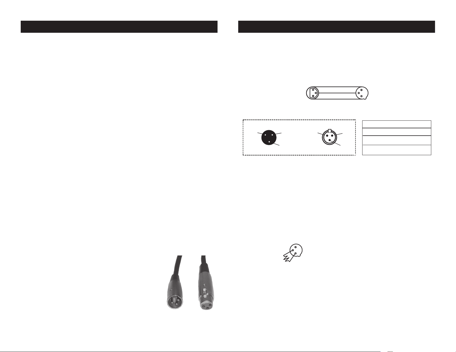
Data Cable (DMX Cable) Requirements (For DMX and Master/Slave
Operation): DMX controller and unit require a approved DMX-512
110 Ohm Data cable for data input and data output (Figure 1). We
recommend Accu-Cable DMX cables. If you are
making your own cables, be sure to use standard
110-120 Ohm shielded cable (This cable may be
purchased at almost all professional sound and
lighting stores). Your cables should be made with
a male and female XLR connector on either end of
the cable. Also remember that DMX cable must be
daisy chained and cannot be split.
Figure 1
Notice: Be sure to follow gures two and three when making your own
cables. Do not use the ground lug on the XLR connector. Do not connect the cable’s shield conductor to the ground lug or allow the shield
conductor to come in contact with the XLR’s outer casing. Grounding
the shield could cause a short circuit and erratic behavior.
COMMON
1
DMX512 IN
3
3-PIN XLR
2
Figure 2
XLR Pin Conguration
Pin 1 = Ground
Pin 2 = Data Compliment (negative)
Pin 3 = Data True (positive)
Figure 4
XLR Male Socket
1 Ground
DMX512 OT
3-PIN XLR
2 Cold
3 Hot
1
3
2
XLR Female Socket
2 Cold
DMX +
DMX -
1 Ground
3 Hot
Figure 3
Special Note: Line Termination.
When longer runs of cable are
used, you may need to use a terminator on the last unit to avoid erratic
behavior. A terminator is a 110-120 ohm 1/4 watt resistor which is connected between pins 2 and 3 of a male XLR connector (DATA + and
DATA -). This unit is inserted in the female XLR connector of the last
unit in your daisy chain to terminate the line. Using a cable terminator
(ADJ part number Z-DMX/T) will decrease the possibilities of erratic
behavior.
Termination reduces signal errors and
1
avoids signal transmission problems
3
and interference. It is always advisable
2
to connect a DMX terminal, (Resistance
120 Ohm 1/4 W) between PIN 2 (DMX-)
ADJ Products, LLC www.adj.com - WiFly NE1 Battery Page 4 ADJ Products, LLC www.adj.com - WiFly NE1 Battery Page 5
Page 4
WiFly NE1 Battery DMX Set Up
WiFly NE1 Battery Controls and Functions
5-Pin XLR DMX Connectors.
Some manufactures use 5-pin DMX-
512 data cables for DATA transmission in place of 3-pin. 5-pin DMX
xtures may be implemented in a 3-pin DMX line. When inserting standard 5-pin data cables in to a 3-pin line a cable adaptor must be used,
these adaptors are readily available at most electric stores. The chart
below details a proper cable conversion.
3-Pin XLR to 5-Pin XLR Conversion
Conductor 5-Pin XLR Male (In)3-Pin XLR Female (Out)
Ground/Shield
Data Compliment (- signal)
Data True (+ signal)
Not Used
Not Used
Pin 1
Pin 2
Pin 3
Pin 1
Pin 2
Pin 3
Pin 4 - Do Not Use
Pin 5 - Do Not Use
876542
13 12 11 10 9
3
ADJ Products, LLC www.adj.com - WiFly NE1 Battery Page 6
1
BATTERY
15 14
ADJ Products, LLC www.adj.com - WiFly NE1 Battery Page 7
Page 5

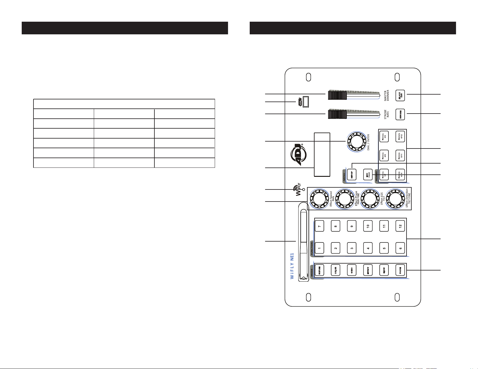
1. WIFLY ANTENNA - This is used to send WiFly wireless DMX signal to
compatible WiFly products.
2. EFFECT ROTARY KNOBS - These knobs are used to adjust fixture
channels and to adjust effect functions.
3. WIFLY INDICATOR - This LED will illuminate when a WiFly signal
enabled and active.
WiFly NE1 Battery Controls and Functions WiFly NE1 Battery Controls and Functions
4. LCD DISPLAY - Displays all current functions and menu data.
5. DIAL/ENTER BUTTON - This dial is used to scroll through menu options
and confirm a selection by pressing it. It is also used to access manual
fixture control mode.
6. STROBE RATE FADER - This fader controls the shutter channel for fix-
tures that include a shutter channel.
7. USB PORT - This USB port is used to upload fixture profiles and
save/upload memory files. Supports most USB drives.
Note: USB stick can be formatted for FAT16 or FAT32.
Note: In order for your controller to recognize your files, they must be
stored in a folder named ADJ-NE1B. The folder cannot have any other
name.
8. MASTER DIMMER FADER - This fader controls the master intensity,
typically tied into the dimmer channel of a fixture.
9. BLACKOUT BUTTON - Activates/Deactivates blackout state.
10. STROBE BUTTON - Press this button to activate/deactivate strobing for
selected fixtures.
11. MEMORY 1-6/7-12 BUTTONS - Used to save/playback memories (can
be static or moving scenes).
12. SET-UP BUTTON - This button is used to enter and exit the settings
menu. You can press this button to view the battery status as well.
13. ESC/PAGE - This button is used to exit the submenu. If you press and
hold this button for at least 3 seconds all output goes to zero. This but-
ton is also used to switch between memory button pages.
14. FUNCTION BUTTONS 1-12 - These buttons are multi-functional
depending on the selected mode.
15. MODE BUTTONS - These buttons are used to change the state of
operation. Note: The PAUSE button will only pause running effects.
ADJ Products, LLC www.adj.com - WiFly NE1 Battery Page 8 ADJ Products, LLC www.adj.com - WiFly NE1 Battery Page 9
1
1. BATTERY - This is the rechargeable battery. To charge the battery simply plug the included I.E.C. cord into a matching power supply. To install
another battery, unscrew the two thumb screws that hold the battery in
place. Slowly slide the battery out. Unhook the connected cable from the
battery and replace with a new battery. Connect the cable as it was before
and slide the new battery into the compartment. NOTE: The battery can
be charged separately from the unit by purchasing a DC adapter. Please
contact an ADJ authourized dealer or visit the ADJ parts website for more
information.
2. DMX OUT - Used to send DMX signal to the compatable LED fixtures.
3. POWER CORD INLET - This cord is designed to match the electrical requirements of the unit. Voltage may vary from venue to venue, when
connecting this unit to a power supply be sure to connect to a matching
power outlet. Never use this xture if the ground prong has been removed
or broken o. The ground prong is designed to reduce the risk of re or
2 43
electrical shock in the event the unit suers from an internal short.
Fuse Holder - This housing stores a 5 amp protective fuse. Never defeat
the fuse, the fuse is designed to protect the electronics in the event of
severe power uctuations. Always be sure to replace the fuse with an
exact match as the one being replaced, unless otherwise told to do so by
an authorized ADJ service technician.
4. POWER SWITCH - Use this switch to power on/off the controller.
WiFly NE1 Battery Battery Charging
To charge the battery simply connect the included I.E.C. cord
to the unit and plug power cord into matching power source
and turn the controllers Power on. To check the battery status,
press the SET UP button or follow the Battery Status instruc-
tions on page 15.
Page 6

WiFly NE1 Battery WiFly Set Up
WiFly NE1 Battery Operation
Set Wiy Channel
1. Press the SET-UP button for two seconds to enter the main menu.
2. Turn the DIAL/ENTER button to menu option 6 (Set wiy channel).
Press the DIAL/ENTER button to enter.
3. Turn the DIAL/ENTER button to set the channel address (00 – 14),
then press the DIAL/ENTER button to conrm.
4. Press and hold the SET-UP button for 2 seconds to exit menu
mode.
Set Wiy Power
1. Press the SET-UP button for two seconds to enter the main menu.
2. Turn the DIAL/ENTER dial to menu option 7 (Set WiFly Power).
Press the DIAL/ENTER button to enter.
3. Turn the DIAL/ENTER dial to turn the WiFly power ON or OFF, then
press the DIAL/ENTER button to enter.
4. Press and hold the SET-UP button for 2 seconds to exit menu
mode.
LOADING FIXTURE PROFILES
NOTE: The WiFly NE1 Battery comes pre-loaded with Generic
xture proles, which include RGB, RGBW, RGBA, RGBWA,
RGBWAU, TRI-WHITE, 36CH 8-Bit ML (M1), and 36CH 16-Bit
ML (M2). See the Generic xture traits chart section on page
19 for channel details. All other proles can be loaded from the
USB stick, which is included. The USB stick includes several
ADJ proles, which are compatible with this controller. Because
the le names are abbreviated, due to character limitations,
please us the “Fixture Prole Details” PDF list to cross reference the les. So your controller runs at optimum speed, please
only load the proles that you will be using. A maximum of 65
proles can be loaded at a time.
1. With the controllers power switch OFF, insert the included
USB drive into the controllers USB port and power ON the con-
troller.
2. Press and hold down the SET-UP button for two seconds to
enter the main menu.
3. Select menu option 1 (Load Light Lib) by pressing the DIAL/
ENTER dial then turn the DIAL/ENTER dial to nd the prole
that you wish to load.
ADJ Products, LLC www.adj.com - WiFly NE1 Battery Page 10
4. Once you have located the prole, press the DIAL/ENTER
dial to load it. The display will momentarily read “Operation
Complete”. Repeat steps 3 and 4 to load additional proles or
press the ESC/PAGE button to exit.
Delete Light Lib
1. Press and hold the SET-UP button for two seconds to enter
the main menu.
2. Turn the DIAL/ENTER dial to menu option 2 (Delete Light
Lib). Press the DIAL/ENTER dial to enter.
3. Turn the DIAL/ENTER dial to nd the prole that you wish to
ADJ Products, LLC www.adj.com - WiFly NE1 Battery Page 11
Page 7

WiFly NE1 Battery Operation
WiFly NE1 Battery Operation
delete or select “delete all lib” to delete all proles. Press the
DIAL/ENTER dial to enter.
4. Turn the DIAL/ENTER dial to select “Yes”. Press the DIAL/
ENTER dial to enter. Press the ESC/PAGE button to exit.
Patch Light Lib
1. Press and hold the SET-UP button for two seconds to enter
the main menu.
2. Turn the DIAL/ENTER dial to menu option 3 (Patch Light Lib).
Press the DIAL/ENTER dial to enter.
3. Turn the DIAL/ENTER dial to nd the prole that you wish to
patch. Press the DIAL/ENTER dial to enter.
4. Press the xture button(s), 1-12, that you wish to patch the
selected prole to and turn the DIAL/ENTER dial to set the
starting address. Press the DIAL/ENTER dial to enter. Press the
ESC/PAGE button to exit.
Delete Patch Light
1. Press and hold the SET-UP button for two seconds to enter
the main menu.
2. Turn the DIAL/ENTER dial to menu option 4 (Delete Light
Patch) then select the xture(s), 1-12, that you wish to delete
from the patch. Press the DIAL/ENTER dial to excute.
3. Turn the DIAL/ENTER dial to select “Yes”. Press the DIAL/
ENTER dial to excute.
Edit Light Lib
Note: WiFly NE1 Battery allows for channel defaults to be set
for PAN, TILT, COLOR, and GOBO channels when the prole is
being created. If you wish to edit these defaults or set automatic defaults for other channels, this is where you do this.
1. Press the SET-UP button for two seconds to enter the main
ADJ Products, LLC www.adj.com - WiFly NE1 Battery Page 12
menu.
2. Select the xture(s), 1-12, that you wish to edit. Turn the
DIAL/ENTER dial to menu option 5 (Edit Light Lib). Press the
DIAL/ENTER dial to enter. Turn the DIAL/ENTER dial to select
the xture that you wish to edit. Press the DIAL/ENTER dial to
save and conrm.
3. Turn the EFFECT dials, 1-4, to adjust the relevant channel
data. Turn the DIAL/ENTER dial to access additional channels.
Press the DIAL/ENTER dial to save and conrm.
Save Data To USB
Note: This option allows you to store all of your controllers data
to the included USB stick. Up to 12 data les can be stored on
the stick. File names are automatically generated as CONFIG01
- CONFIG12. These le name cannot be changed. If changed,
the controller will not recognize them when you attempt to upload it.
1. Press the SET-UP button for two seconds to enter the main
menu.
2. Turn the DIAL/ENTER dial to menu option 8 (Save Data to
USB). Press the DIAL/ENTER dial to enter
3. Using the function buttons 1-12, select the le button that
you wish to save to. If you select button #4, for example, the le
will be stored on the USB stick as “CONFIG04”.
Note: If you have a ashing green FUNCTION button, this
means you already have data stored in that location. So
if you do not want to overwrite it, do not select a ashing
green button.
Load Data From USB
Note: This option can only be used if you already have data
from a WiFly NE1 Battery controller stored on your USB stick.
Data les will appear in your computer as CONFIG01-CON-
ADJ Products, LLC www.adj.com - WiFly NE1 Battery Page 13
Page 8

WiFly NE1 Battery Operation
WiFly NE1 Battery Operation
FIG12. These les cannot be renamed. Otherwise, the controller
will not recognize them.
1. Press and hold the SET-UP button for two seconds to enter
the main menu.
2. Turn the DIAL/ENTER dial to menu option 9 (Load Data from
USB). Press the DIAL/ENTER dial to enter.
3. Usin the FUNCTION buttons 1-12, select the le button that
you wish to upload into your computer.
Note: Green ashing FUNCTION buttons indicate there is
data stored there and are available to be selected. If you
select a non-ashing button, you will get a “Operation Failure!” error.
Format The USB
Note: This function should be used with caution as all data on
the USB stick will be erased. It is highly recommended that you
back up all USB stick les to your computer before proceeding.
1. With the controllers power switch OFF, insert the USB stick
into the controllers USB port and power on the controller.
2. Press the SET-UP button for two seconds to enter the main
menu.
1. Press the SET-UP button for two seconds to enter the main
menu.
2. Turn the DIAL/ENTER dial to menu option 11 (Strobe Settings). Press the DIAL/ENTER dial to enter.
3. Turn the DIAL/ENTER dial to select between “Latch” and
“Flash”. Press the DIAL/ENTER dial to conrm your selection.
Power Save Mode
1. Press the SET-UP button for two seconds to enter the main
menu.
2. Turn the DIAL/ENTER dial to menu option 12 (Power Save
Mode). Press the DIAL/ENTER dial to enter.
3. Turn the DIAL/ENTER dial to highlight either “Yes” or “No”.
Press the DIAL/ENTER dial to execute.
Battery Status
1. Press the SET-UP button for two seconds to enter the main
menu.
2. Turn the DIAL/ENTER dial to menu option 13 (Battery Status).
Press the DIAL/ENTER dial to enter. The battery status will now
be shown.
3. Turn the DIAL/ENTER dial to menu option 10 (Format the
USB disk). Press the DIAL/ENTER dial to enter.
4. Turn the DIAL/ENTER dial to select “YES”. Press the DIAL/
ENTER dial to excute.
Strobe Settings
This setting allows you to choose the manner in which the
STROBE button functions. It allows you to choose between
Latch and Flash. Selecting Latch will make the STROBE button
latch ON/OFF and selecting Flash will make it momentary, last-
ing only as long as you press the hold down the button.
ADJ Products, LLC www.adj.com - WiFly NE1 Battery Page 14
Delete Memory
Note: This function should be used with caution as it will delete all memories stored in MEMORY buttons 1-12. The default
passcode to execute this function is 1668. If your passcode has
changed, you will need to input it to execute this function.
1. Press the SET-UP button for two seconds to enter the main
menu.
2. Turn the DIAL/ENTER dial to menu option 14 (Delete Memory). Press the DIAL/ENTER dial to enter.
3. Turn the DIAL/ENTER dial to select the memory that you wish
ADJ Products, LLC www.adj.com - WiFly NE1 Battery Page 15
Page 9

WiFly NE1 Battery Operation
WiFly NE1 Battery Operation
to delete. Press the DIAL/ENTER dial to execute.
4. Using the FUNCTION 1-12 buttons, input the passcode.
5. Turn the DIAL/ENTER dial to select “Yes”. Press the DIAL/
ENTER dial to execute.
Delete all data
Note: This function should be used with caution as it will de-
lete all data stored in your controller. Deleted data will include
all proles and MEMORY button les. The default passcode to
execute this function is 1668. If your passcode has changed,
you will need to input it to execute this function.
1. Press the SET-UP button for two seconds to enter the main
menu.
2. Turn the DIAL/ENTER dial to menu option 15 (Delete All
Data). Press the DIAL/ENTER dial to enter.
4. Using the FUNCTION 1-12 buttons, input the passcode.
5. Turn the DIAL/ENTER dial to select “Yes”. Press the DIAL/
ENTER dial to execute.
Factory Setting
Note: This function should be used with caution as it will delete
all data, memories, and return all settings, including passcode,
back to factory default. The default passcode to execute this
function is 1668. If your passcode has changed, you will to
input it to execute this function.
1. Press the SET-UP button for two seconds to enter the main
menu.
2. Turn the DIAL/ENTER dial to menu option 16 (Factory Settings). Press the DIAL/ENTER dial to enter.
4. Using the FUNCTION 1-12 buttons, input the passcode.
5. Turn the DIAL/ENTER dial to select “Yes”. Press the DIAL/
ADJ Products, LLC www.adj.com - WiFly NE1 Battery Page 16
ENTER dial to execute.
Change Passcode
1. Press the SET-UP button for two seconds to enter the main
menu.
2. Turn the DIAL/ENTER dial to menu option 17 (Change Password). Press the DIAL/ENTER dial to enter.
4. Using the FUNCTION 1-12 buttons, input the current pass-
code.
5. Using the FUNCTION 1-12 buttons, input your new four digit
passcode, then re-input your new passcode a second time to
conrm.
Firmware Version
Note:This is a read only menu option that will display the controllers current software version.
1. Press the SET-UP button for two seconds to enter the main
menu.
2. Turn the DIAL/ENTER dial to menu option 18 (Firmware Version). Press the DIAL/ENTER dial to enter. Press the ESC/PAGE
button to exit.
Fixture Control, Saving, & Playing Memories
Note: Although the generic proles may work for you, it is recommended that you load and use the custom proles that were
provided on the USB sitck that was included with your controller. The custom proles may oer you additional control and
features that the generic proles do not include. If you wish to
use the custom proles, please refer to the LOADING FIXTURE
PROFILES section of this user manual and load them before
proceeding. After you have patched your xtures, you can con-
trol and save memories using the following steps.
1. Press the FIXTURE button then select the xtures, using the
ADJ Products, LLC www.adj.com - WiFly NE1 Battery Page 17
Page 10

Profile DMXChannels ChannelInfo
WiFly NE1 Battery Operation
WiFly NE1 Battery Operation
FUNCTION 1-12 buttons, that you want to control. If you are
using multiple xtures of the same type and want to control
them at the same time, you can press the rst and last buttons
so all xtures in between are selected at the same time. For example, I have patched 6 xtures on buttons 1-6, to select them
all quickly, I would simultaneously press buttons 1 & 6 so all 6
xtures are selected.
2. Press the COLOR button and add a color by using the
FUNCTION 1-12 buttons. Turn the DIAL/ENTER dial to switch
between two pages of preset colors (Note: your xture must
support this feature to function).
3. Press the GOBO button and add a gobo by using the FUNCTION 1-12 buttons. Turn the DIAL/ENTER dial to switch between two pages of preset gobos (Note: your xture must sup-
port this feature to function).
4. Press the EFFECT button and add an eect by using the
FUNCTION 1-12 buttons. Turn the DIAL/ENTER dial to switch
between three pages of eects. In the display, you will see ML
EFFECT (for moving lights) and RGB EFFECT 1 and RGB EFFECT 2 (for RGBWA+UV LED’s) plus the speed, phase, size,
and direction settings, which can be controlled from the four
EFFECT rotary dials. You can pause an eect at any time by
pressing the PAUSE button. (Note: your xture must support
this feature to function).
5. Press the SHOW button and enable a show by using the
FUNCTION 1-12 buttons. (Note: your xture must support this
feature to function).
6. You can also set all channel values manually. If you have
already set your scene and want to store it. please see step 7
now. To make manual channel adjustments, press the FIXTURE
button, then press the DIAL/ENTER dial for two seconds, the
display will list channels 1-4 along with their current values.
Use the four EFFECT dials to adjust each channel listed in the
display. Channels are displayed four at a time. To access additional channels, turn the DIAL/ENTER dial clockwise and
counter-clockwise.
7. To save your current output, press and hold down any of the
six MEMORY buttons until the display reads “Operation Complete!”. Press that same MEMORY button a second time to
playback from that memory location, it should illuminate solid
green. Repeat steps 1-6 to store additional memories. There
are two memory banks. To access the secondary memory bank
press the ESC/PAGE button. If there is a memory running, that
MEMORY button will ash letting you know that is actively running in the other bank. If your memory includes an “EFFECT”,
you can pause the eect by pressing the PAUSE button.
8. You can trigger the STROBE button at any time during playback. The STROBE button will function relative to the STROBE
RATE fader setting. Adjusting your STROBE RATE fader will
give you DMX control over your xtures shutter or RGBWA+UV
channels. This function cannot be stored into a memory.
9. You can manually adjust the MASTER DIMMER fader at any
time during playback to set the overall intensity for you active
xtures. This function cannot be stored into a memory.
WiFly NE1 Battery Generic Fixture Traits
RGB 3 CH1=RED,CH2=GREEN,CH3=BLUE
RGBW 4 CH1=RED,CH2=GREEN,CH3=BLUE,CH4=WHITE
RGBA 4 CH1=RED,CH2=GREEN,CH3=BLUE,CH4=AMBER
RGBWA 5 CH1=RED,CH2=GREEN,CH3=BLUE,CH4=WHITE,CH5=AMBER
RGBWAU 6 CH1=RED,CH2=GREEN,CH3=BLUE,CH4=WHITE,CH5=AMBER,CH6=UV
TRIWHITE 3 CH1=WARMWHITE,CH2=COOLWHITE,CH3=AMBER
36CHML8BIT 36 CH1=PAN,CH2=TILT,CH3=CH3,CH4=CH4,...CH35=CH35,CH36=CH36
36CHML16BIT 36 CH1=PAN,CH2=PANFINE,CH3=TILT,CH4=TILTFINE,CH5=CH5,CH6=CH6,...CH35=CH35,CH36=CH37
ADJ Products, LLC www.adj.com - WiFly NE1 Battery Page 18
ADJ Products, LLC www.adj.com - WiFly NE1 Battery Page 19
Page 11

WiFly NE1 Battery Fixture Profile Details
1
2
3
11 Dotz Flood
14
16
17
18
19
22
23
24
25
27
29
30
33
34
35
36
Generic RGBW LED
RGBW
Generic RGBWAU LED
ID44-12, ID44-14
CRAZ8-1, CRAZ8-9, CRAZ8-12, CRAZ8-15
Inno Color Beam Z19
Inno Pocket Beam
Inno Beam LED
Inno Spot LED
WWCWA
Inno Spot LED Wifly
Inno Pocket Roll
Inno Pocket Wash
Inno Pocket Scan
Inno Spot Pro Pearl
Inno Spot PRO
ICB19-14
IPB-10, IPB-11, IPB13
Item Name
Event Bar
Inno Color Beam Quad 7
Inno Color Beam 12
EVBAR-12, EVBAR-14, EVBAR-25
name indicate channel mode)
ISLEDW10
Inno Spot Elite
ICBQ7-1, ICBQ7-13
Generic 36ch ML 16-bit
36CH-M2
DFLD-3, DFLD-4, DFLD-6, DFLD-9A, DFLD-9B
Freq Matrix Quad
FMAQD-2, FMAQD-5, FMAQD-18
Generic RGB LED
RGB
IPS-9, IPS-11
Inno Pocket Spot Pearl
IPSP-9, IPSP-11
Inno Pocket Spot Twins
IPST19, IPST23
Inno Scan HP
ISHP-9, ISHP-12
IPW-9, IPW-11, IPW-19, IPW-21
Dotz Par-100
INPSCN-6
Inno Roll HP
ISLED-10
ISPPRL14
FPQA12-1, FPQA12-2, FPQA12-3, FPQA12-4,
FPQA12-5, FPQA12-6, FPQA12-7, FPQA12-8
Inno Pocket Fusion
IPF-2, IPF-6, IPF-8, IPF-9, IPF-11
IBLED-12, IBLED-14
IRHP-9
ISPEL-15
ICB12-9, ICB12-16
Zipper
ZIPPR-1, ZIPPR-3, ZIPPR-11
Quad Phase HP
Nucleus LED
NUCLS-4
Starburst
Stinger
STNGR-10
Vizi Beam Hybrid 2R
VBH2R-10, VBH2R-12
WBQA5-4, WBQA5-5, WBQA5-6, WBQA5-7,
VB5R-10, VB5R-12
Vizi Spot 5R
VS5R-11, VS5R-13
Sniper 2R
PPBAR-1, PPBAR-4
SN2R-14, SN2R-16, SN2R-18
X-Move LED 25R
QSPRO-32
Warlock
Vizi Beam 5RX
Mega Tri Par Profile Plus
Quad Scan Pro
KAOS-2, KAOS-6, KAOS-15, KAOS-23
WiFly NE1 Battery Fixture Profile Details
NO.
Generic 36ch ML 8-bit
Generic RGBA LED
4
5
Generic RGBWA LED
6
7
Generic Tri White LED
8
COB Cannon Wash
9
Crazy 8
10
12
Event Bar Q4
13
Flat Par QA12XS
15
Illusion Dotz 3.3
Illusion Dotz 4.4
20
Inno Color Beam LED
21
Inno Color Beam Z7
ADJ-NE1 Fixture Profile List
File Names (Numbers at the end of each file
36CH-M1
RGBA
RGBWA
RGBWAU
COBCWS-1, COBCWS-2, COBCWS-3, COBCWS-
4, COBCWS-5, COBCWS-6, COBCWS-7,
DP100-3, DP100-4, DP100-5, DP100-9
ID33-12, ID33-13
ICBL-1, ICBL-13
ICBZ7-14
NO.
Kaos
40
Mega Par Profile Plus
41
Item Name
42
43
Pixel Pulse Bar
44
45
46
47
Sweeper Beam Quad LED
48
49
50
Vizi Beam 5R
51
52
53
54
Vortex 1200
55
56
WiFly Bar QA5
58
WiFly EXR HEX5IP
57
WiFly Par QA5
58
58
59
File Names (Numbers at the end of each file
name indicate channel mode)
MPPP-4, MPPP-5, MPPP-6, MPPP-9, MPPP-10
QPHP-4
SBQLED-6
SBST-13
VB5RX-16, VB5RX-19
VTEX-14, VTEX-15, VTEX-17
WARLOCK8
WBQA5-8
WEH5IP6, WEH5IP7, WEH5IP8, WEH5IP11,
WEH5IP12
WPQA5-1, WPQA5-2, WPQA5-3, WPQA5-4,
WPQA5-5, WPQA5-6, WPQA5-7, WPQA5-8
XML25R-9
26
28
Inno Pocket Spot
31
32
37
38
39
ADJ Products, LLC www.adj.com - WiFly NE1 Battery Page 20 ADJ Products, LLC www.adj.com - WiFly NE1 Battery Page 21
IPROLL-6
ISPRO-14
Page 12

WiFly NE1 Battery Warranty
MANUFACTURER’S LIMITED WARRANTY
A. ADJ Products, LLC hereby warrants, to the original purchaser, ADJ Products, LLC products
to be free of manufacturing defects in material and workmanship for a prescribed period from
the date of purchase (see specific warranty period on reverse). This warranty shall be valid only if the
product is purchased within the United States of America, including possessions and
territories. It is the owner’s responsibility to establish the date and place of purchase by acceptable
evidence, at the time service is sought.
B. For warranty service you must obtain a Return Authorization number (RA#)
before sending back the product–please contact ADJ Products, LLC Service Department
at 800-322-6337. Send the product only to the ADJ Products, LLC factory. All
shipping charges must be pre-paid. If the requested repairs or service (including
parts replacement) are within the terms of this warranty, ADJ Products, LLC will pay return
shipping charges only to a designated point within the United States. If the entire instrument is
sent, it must be shipped in it’s original package. No accessories should be shipped with the product. If
any accessories are shipped with the product, ADJ Products, LLC shall have no liability whatsoever for
loss of or damage to any such accessories, nor for the safe return thereof.
C. This warranty is void if the serial number has been altered or removed; if the product is modified in any
manner which ADJ Products, LLC concludes, after inspection, affects the reliability of the product; if the
product has been repaired or serviced by anyone other than the ADJ Products, LLC factory unless prior
written authorization was issued to purchaser by ADJ Products, LLC; if the product is damaged because
not properly maintained as set forth in the instruction manual.
D. This is not a service contract, and this warranty does not include maintnance, cleaning or periodic check
up. During the period specified above, ADJ Products, LLC will replace defective parts at its expense
with new or refurbished parts, and will absorb all expenses for warranty service and repair labor by
reason of defects in material or workmanship. The sole responsibility of ADJ Products, LLC under this
warranty shall be limited to the repair of the product, or replacement thereof, including parts, at the sole
discretion of ADJ Products, LLC. All products covered by this warranty were manufactured after August
15, 2012, and bear indentifying marks to that effect.
E. ADJ Products, LLC reserves the right to make changes in design and/or improvements upon its products
without any obligation to include these changes in any products theretofore manufactured.
No warranty, whether expressed or implied, is given or made with respect to any accessory supplied with
products described above. Except to the extent prohibited by applicable law, all implied warranties made
by ADJ Products, LLC in connection with this product, including warranties of merchantability or fitness,
are limited in duration to the warranty period set forth above. And no warranties, whether expressed or
implied, including warranties of merchantability or fitness, shall apply to this product after said period
has expired. The consumer’s and/or Dealer’s sole remedy shall be such repair or replacement as is
expressly provided above; and under no circumstances shall ADJ Products, LLC be liable for any loss or
damage, direct or consequential, arising out of the use of, or inability to use, this product.
This warranty is the only written warranty applicable to ADJ Products, LLC Products and
supersedes all prior warranties and written descriptions of warranty terms and conditions heretofore
published.
MANUFACTURER’S LIMITED WARRANTY PERIODS:
•LightingProducts=1-year(365days)LimitedWarranty(Such as: Special Effect Lighting,
Intelligent Lighting, UV lighting, Strobes, Fog Machines, Bubble Machines, Mirror Balls, Par Cans,
Trussing, Lighting Stands etc. excluding LED and lamps)
•LaserProducts=1Year(365Days)LimitedWarranty(excluding laser diodes which have a 6 month
limited warranty)
•L.E.D.Products=2-year(730days)LimitedWarranty(excluding motors, PCB boards, and power
supplies, which have a 1-year (365 day Limited Warranty) batteries which have a 180 day limited war-
ranty). Only the L.E.D.s carry a 2-year warranty (excludingStarTecSerieswhichacarriesa1Year
LimitedWarranty)Note:2YearWarrantyonlyappliestopurchaseswithintheUnitedStates.
•ADJDMXControllers=2Year(730Days)LimitedWarranty(excluding faders and tact switches)
ADJ Products, LLC www.adj.com - WiFly NE1 Battery Page 22
WiFly NE1 Battery Specifications
Specifications
POWER SUPPLY: 100-240V 50/60HZ
POWER CONSUMPTION: 8.1 Watts
WIRELESS FREQUENCY: 2.4 GHz DSSS
OUTPUT: 3-Pin XLR
DIMENSIONS: 12.8” (L) x 7.25” (W) x 3.25” (H)
325 x 185 x 80mm
WEIGHT: 6 lbs./ 2.9 kgs.
BATTERY LIFE: 10 Hours
BATTERY CHARGE TIME: 4 Hours
BATTERY: 11.1V 2.2AH
WARRANTY: 1 Year (365 Days)
Please Note: Specications and improvements in the design
of this unit and this manual are subject to change without any
prior written notice.
ADJ Products, LLC
6122 S. Eastern Ave. Los Angeles, CA 90040 USA
Tel: 323-582-2650 / Fax: 323-725-6100
Web: www.adj.com / E-mail: info@americandj.com
A.D.J. Supply Europe B.V.
Junostraat 2
6468 EW Kerkrade
The Netherlands
service@adjgroup.eu / www.adj.eu
Tel: +31 45 546 85 00 / Fax: +31 45 546 85 99
 Loading...