

Page 1

AVIATOR-32
USER'S MANUAL
5
3
4
2
1
LATCH
FLASH
POWER
American DJ
Special Effect Lighting & Entertainment Products
HEATING
PAGE-1
87 6
PAGE-2
STAND BY
PAGE-3
PAGE-4
LAST
PAGE
PROGRAM
NEXT
READY
GROUP
FOG MACHINE
GROUP-1
GROUP-2
DMX IN
EXIT
UP
SPEED
MODE
DOWN
DMX INLOGIC
R
STAND BY
Please read before use
English
Page 2
Contents
Features 1
General Instructions 2
1. Overview 3
1.1 Front Panel 3
1.2 Rear Panel 5
2. Operation Guide 6
2.1 Set-Up 6
2.2 Basic Operation 6
2.2.1 Latch Buttons 7
2.2.2 Flash Buttons 7
2.2.3 Select Chase Group 7
2.2.4 Pattern Mode 8
2.2.5 Audio Mode 10
American DJ
Improvement and changes to
this manual, specifications
and design, may be made at
any time without prior notice.
ALL RIGHTS RESERVED
2.2.6 Logic Mode 10
2.2.7 DMX Mode 12
2.2.8 Program Mode 13
R
2.2.9 Clear Memory 15
Technical Specifications 16
American DJ
Los Angeles, CA 90058 USA
R
Page 3
Features
Thank you for purchasing this American DJ product.
This Aviator-32 features include:
Serves as a Switch Pack or a 32 channel controller, depending
upon the current operating mode.
Flash button allows to momentarily flash the channel
Latch button allows to turn on/off or latch the channel
3-pin standard DMX IN/OUT ports
Power failure memory.
4 digits Segment Display shows current activity
and function state.
1
Page 4
General Instructions
2
Page 5
1. Overview
1.1 Front Panel
3
LATCH
FLASH
POWER
15
PROGRAM
GROUP-1
GROUP-2
DMX IN
14
HEATING
READY
GROUP
FOG MACHINE
SPEED
LOGIC
EXIT
UP
MODE
DOWN
STAND BY
DMX IN
5
4
5
3
4
2
1
PAGE-1
87 6
PAGE-2
STAND BY
PAGE-3
PAGE-4
LAST
PAGE
NEXT
1 2
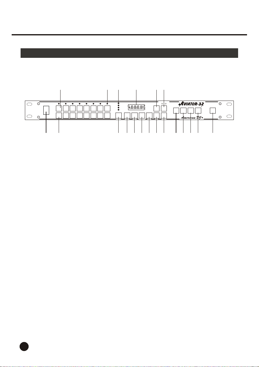
1. Power Switch
2. Flash Buttons
3. Latch Buttons
4. Channel LEDs
5. Page LEDs
6. Page Button
7. Segment Display
8. Next Button
9. Last Button
10. Program Button
678 9
10
11 12
13
18
16
19 20
17
This switch turns the main power on and off.
These 8 Flash buttons are used to bring an individual
channel to full intensity.
These 8 Latch buttons are used to turn on/ off or Latch
the corresponding channel.
These 8 LEDs show the current activity or intensity of
the relevant channel.
The LED lights when the page is selected.
Tap the button to scroll through the four pages until the
page is selected.
Shows the current programming or function state.
Tap this button to store the scene you've set as one
step and to program next step from 01 to 16.
Tap this button to revert to the last step.
The button is used to program or run the chase
pattern and disable other function modes.
3
Page 6

1. Overview
1.1 Front Panel
11. Exit Button
12. Up Button
13. Down Button
14. Group Button
15. Fog Machine Button
16. Mode Button
17. Speed Button
18. Logic Button
19. DMX In Button
20. Stand By Button
The button is used to exit from the Program or
DMX mode.
Tap the button to increase the display value.
Tap the button to decrease the display value.
Tap the button to select the chase group between
Group 1 and Group 2 indicated by the lit LED.
Activates Fog Machine function.
Press to select operating mode between Pattern
mode and Audio mode.
Activates Speed setting except that Audio mode
is active.
Tap to activate Logic mode.
Tap to activate DMX mode with the exception that
Speed setting is active.
This button is used to disable all output.
4
Page 7
1. Overview
1.2 Rear Panel
AUDIO IN
LINE IN
0.1V~2VP-P
4
PIN
1
CH
VCC 4 3 2 1 8 7 6 5
1 7653 42
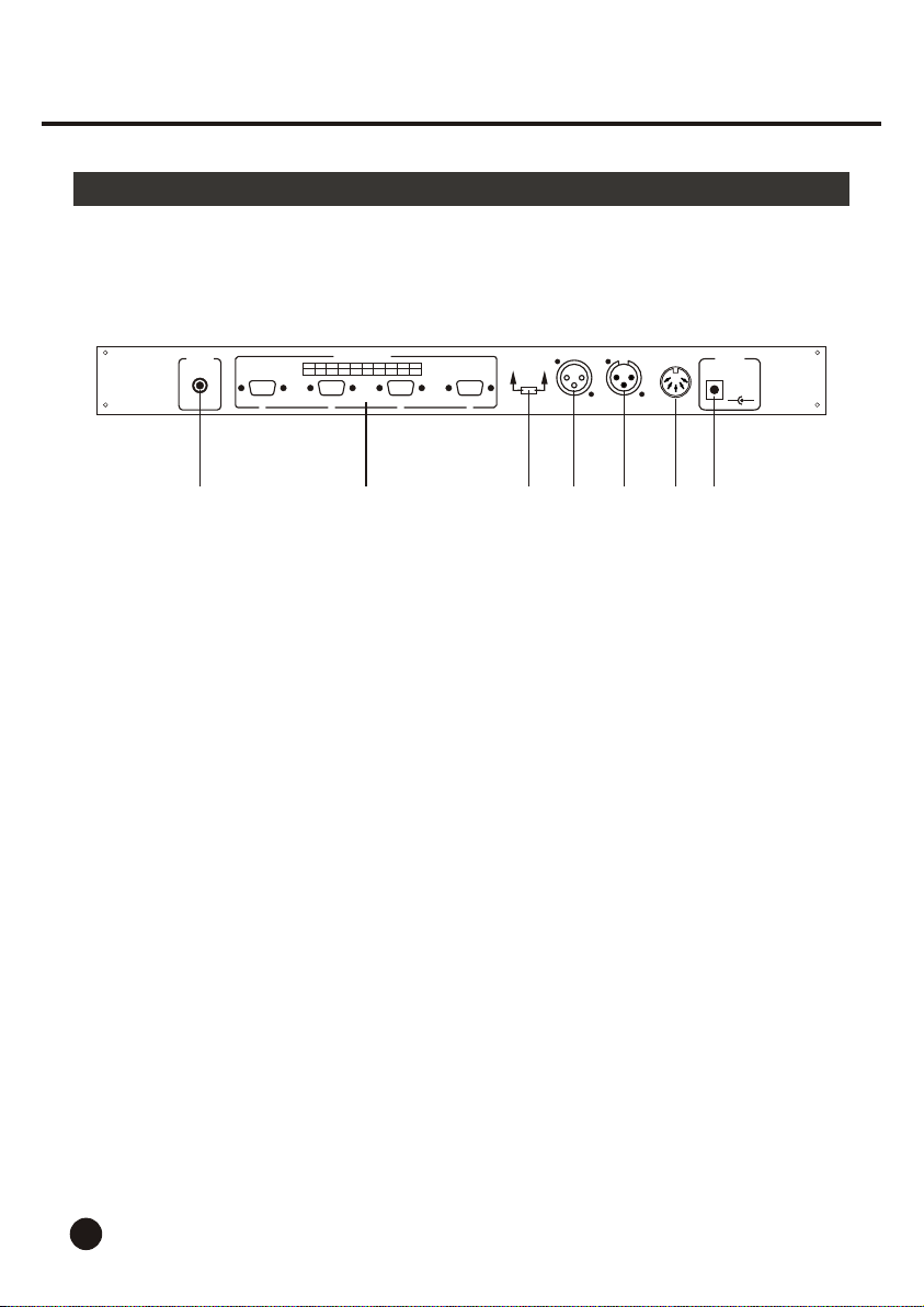
1. Audio Input
2. Control Output
3. DMX Polarity Select
4. DMX Output
5. DMX Input
6. Fog Machine Connector
CONTROL OUTPUT
2 3 4 5 6 7 8 9
3
1=GROUND
1=GROUND
2=DATA+
2=DATA-
3=DATA-
3=DATA+
DMX OUT
2
Polarity Select
1
DMX IN
FOG MACHINE
DC INPUT
DC IN
+9V~+12V
500mA min.
Connects an external audio source directly to the
unit. This will provide a more accurate audio source
when the internal Mic is not sensitive enough or
when the unit is mounted far away from the speaker.
These 4 outputs connect to the Relay Pack using
9 pin extension cables.
Move to select Data polarity of DMX output.
This connector sends the DMX signal through to
the next DMX device.
This connector receives DMX signal.
Connects to the Fog Machine.
++--
7. DC Input
5
This input jack is used to plug in an external power
supply (9V-12V DC, 500 mA min.).
Page 8

2. Operation Guide
2.1 Set-Up
1. Connected the supplied 9 pin com cable from the output on the rear of this unit
to the input of the power pack.
2. Connect your lighting effects to the channel output on the power pack.
3. Plug in a DMX controller to your unit via the 3-pin XLR cables.
4. After you have made all your connections, turn the main power on.
5. Wait for at least 1 second to turn the main power on a second time.
2.2 Basic Operations
General
This unit is a 32 channel controller, has 4 Pages of banks, each bank consisting
of two separate chase groups for 8 channel output. Each chase group has three
operating modes: Pattern Mode, Audio Mode and Logic Mode.
This unit consists of 8 Latch buttons allowing to turn on/off and latch the matching
channels, 8 Flash buttons to momentary turn the corresponding channel on, a
Program button enabling you to program a chase pattern including 16 steps x 4
pages, a DMX In button to activate the DMX function.
6
Page 9
2. Operation Guide
2.2.1 Latch Buttons
LATCH
2.2.2 Flash Buttons
FLASH
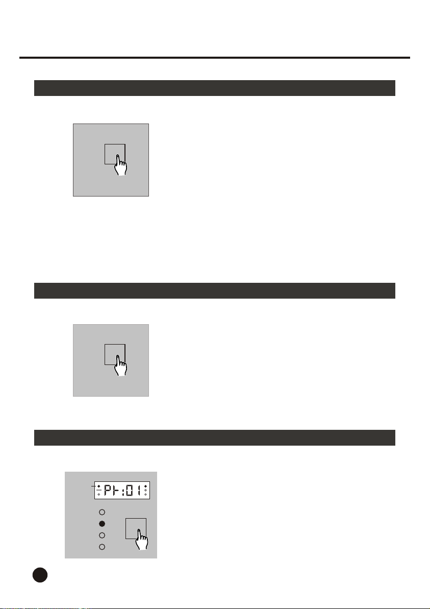
The 8 Latch buttons are used to turn on/off or
latch the matching channel. Latch 1-4 buttons
are used for Group 1 while Latch 5-8 buttons
for Group 2.
Pressing and holding down the button for two
seconds will change the channel between On
and Off.
When the channel is Off, the channel goes out
regardless of the chase of pattern.
When the channel is On, tap the Latch button
to change the channel between On and Latch.
If the channel is On, the channel is activated
by the chase of pattern. If the channel is Latch,
the channel lights regardless of the chase of
pattern.
The 8 Flash buttons are used to momentarily light
the corresponding channel.
Pressing and holding down the button will give
full intensity to the corresponding channel, release
will deactivate this function.
2.2.3 Select Chase Group
Stand By
PAGE-1
PAGE-2
PAGE-3
PAGE-4
PAGE
7
1. Turn the main power on, the Segment Display
shows the operating mode of last change and
the Stand By LED blinks.
Tap the Page button to scroll through the 4 pages,
the red LED indicates which page you've selected.
Page 10
2. Operation Guide
2.2.3 Select Chase Group
GROUP
2.2.4 Pattern Mode
MODE
Group-2
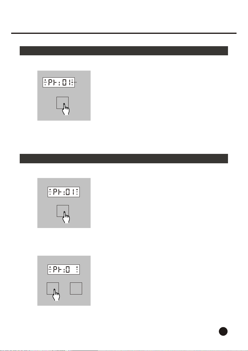
2. Tap the Group button to select the chase group
from Group 1-2, the Group LED lights indicating
the group.
1. Press the Mode button until the Segment Display
shows "PR" followed by two numbers.
2
OR
UP DOWN
2. Tap the Up or Down button to select desired
pattern from Patterns 01-16.
8
Page 11
2. Operation Guide
2.2.4 Pattern Mode
03:00
SPEED
Group-2
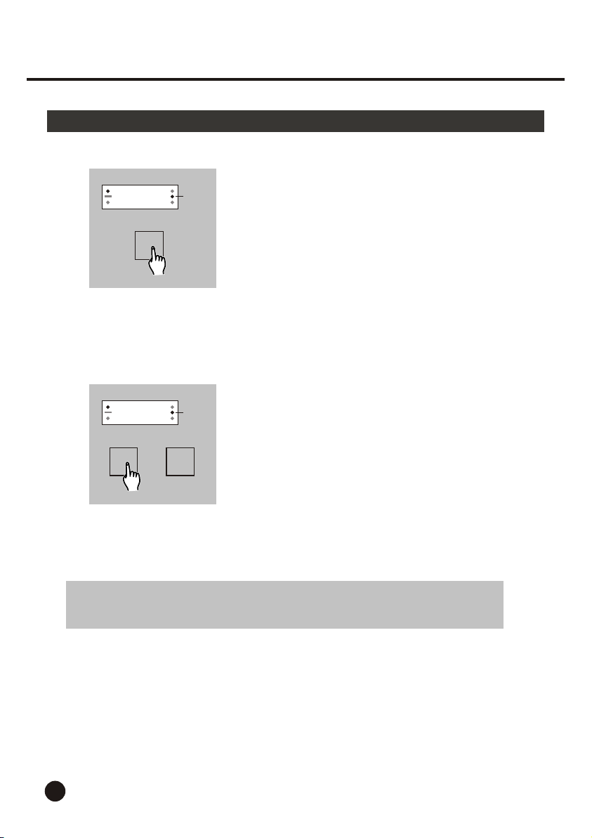
3. Tap the Speed button, the Segment Display
shows the current chasing speed indicated
by three or four numbers.
If the Segment Display shows three digits,
the speed is in second cycle.
For example: 3:00 indicates 3 seconds.
If the Segment Display shows four digits,
the speed is in minute cycle.
For example: 03:00 indicates 3 minutes.
03:00
UP DOWN
NOTE: In the course of speed setting, the Logic, Program and DMX In
buttons are disabled.
Group-2
OR
4. Tap the Up or Down button to change the
speed from 0.10 second to 10 minutes.
Each tap will change the speed once, and
pressing and holding down will change the
speed quickly.
9
Page 12
2. Operation Guide
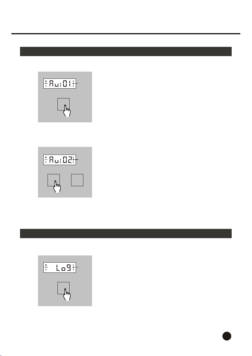
2.2.5 Audio Mode
MODE
OR
UP DOWN
2.2.6 Logic Mode
Group-2
Group-2
1. Press the Mode button until the Segment Display
shows "Au" followed by two numbers.
2. Tap the Up or Down button to select desired
pattern from Patterns 01-16. The pattern will
chase on audio beat and the Speed button is
disabled.
LOGIC
Group-2
In Logic Mode, the "latch" and "flash" function
will take the channel out from the chase when
the chase is running.
1. Tap the Logic button, the Segment Display
shows "Log" indicating Logic mode is active.
10
Page 13
2. Operation Guide
2.2.6 Logic Mode
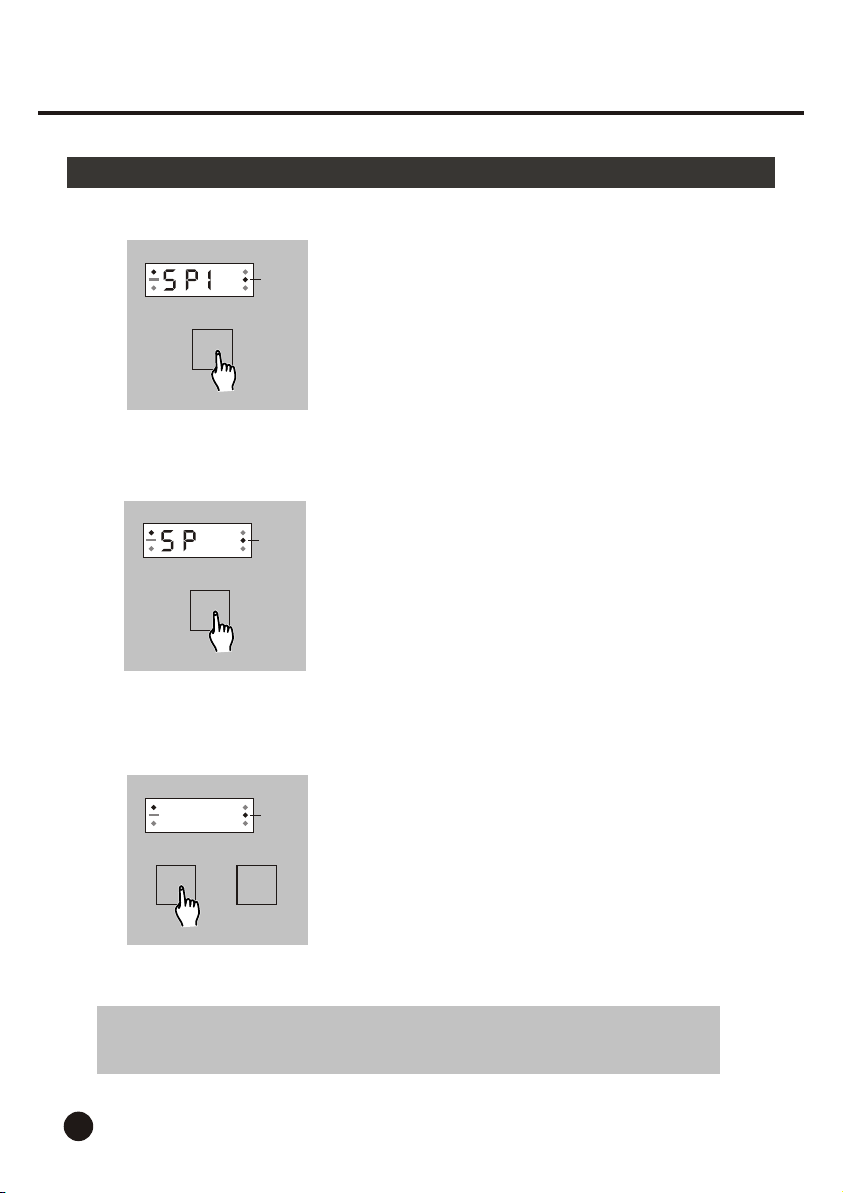
SPEED
2
SPEED
03:00
OR
UP DOWN
Group-2
Group-2
Group-2
2. Tap the Speed button, the Segment Display
shows "SP" followed by one number from 1-4
indicating channel 1-4.
3. Tap the Speed button a second time to
change the channel.
Each tap of the Speed button will change
the channel once.
4. Tap the Up or Down button to change the
speed from 0.10 second to 10 minutes.
Each tap will change the speed once, and
pressing and holding down will change the
speed quickly.
NOTE: In the course of speed setting, the Program and DMX In buttons
are disabled.
11
Page 14
2. Operation Guide
2.2.7 DMX Mode
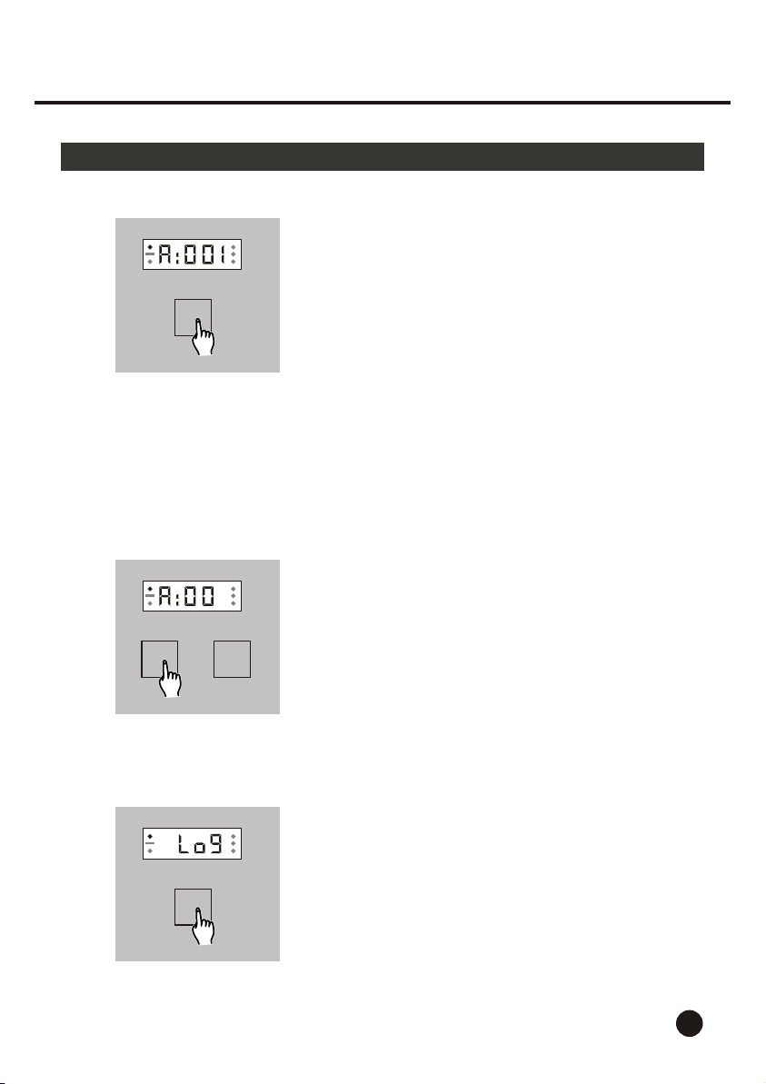
DMX IN
1. Tap the DMX In button, the Segment Display
shows "A" followed by three numbers which
indicates the DMX address for the starting
DMX channel.
Now you may use the unit as a 32 channel
DMX pack which allows you to control the
turning on or off of the channel 1-32 through
the DMX controller. If the DMX value is less
than 20%, the channel will go out. If the level
amounts to or exceeds 20%, the channel
will light.
This unit also allows you to control the Stand
By function if the DMX address for channel
33 is available.
5
OR
UP UP
EXIT
2. Tap the Up or Down button to select the DMX
address from 001-512. Be sure your DMX
controller's address matches the DMX address
you've set. If the DMX address is not available
for the channel, the channel will go out.
For example, if the DMX address is 512,
channels 2-31 will go out.
3. Tap the Exit button to exit from DMX mode,
this unit will return to normal operating mode.
12
Page 15
2. Operation Guide
2.2.8 Program Mode
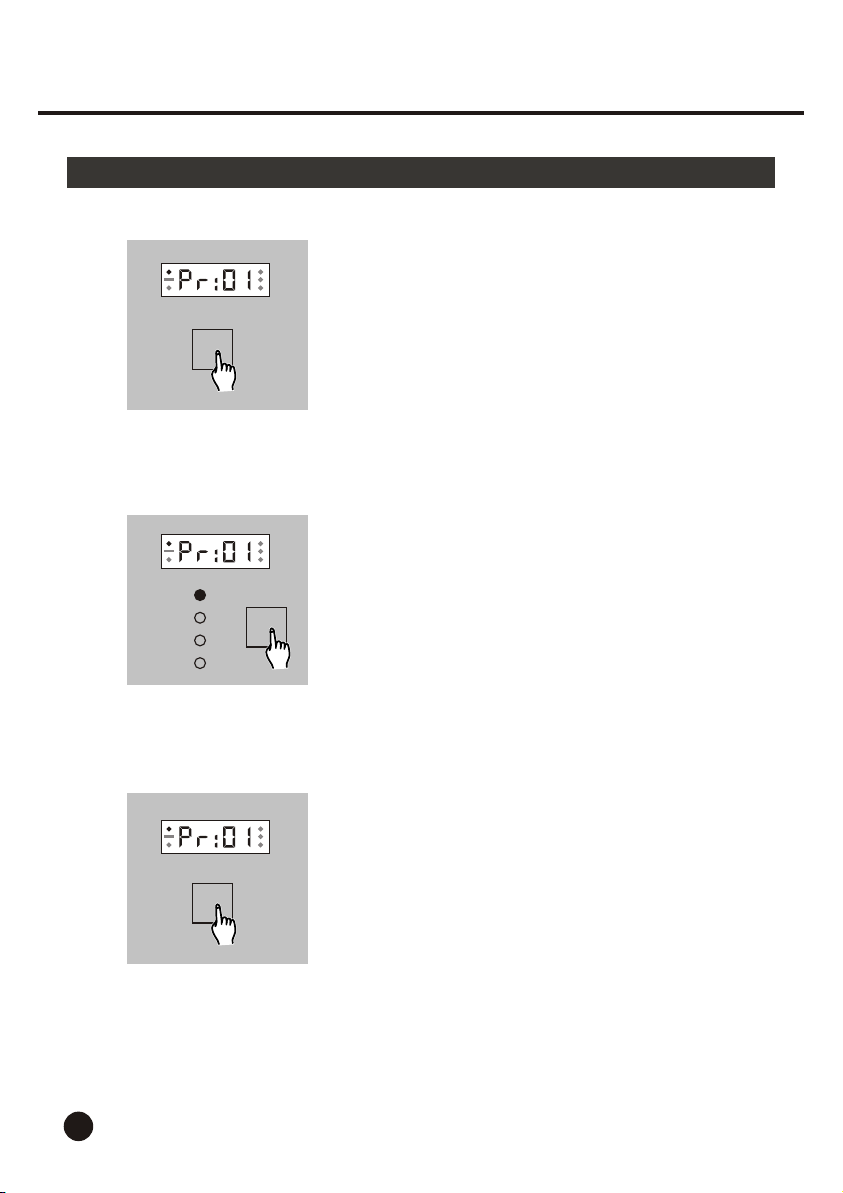
PROGRAM
PAGE-1
PAGE-2
PAGE-3
PAGE-4
PAGE
1. Tap the Program button, the Segment Display
shows "PR" followed by "01" which prompts
Program mode is active.
2. Tap the Page button to select the page
indicated by the lit LED.
13
3. Create desired scene by tapping the Latch
buttons.
LATCH
Page 16
2. Operation Guide
2.2.8 Program Mode
2
NEXT
PROGRAM
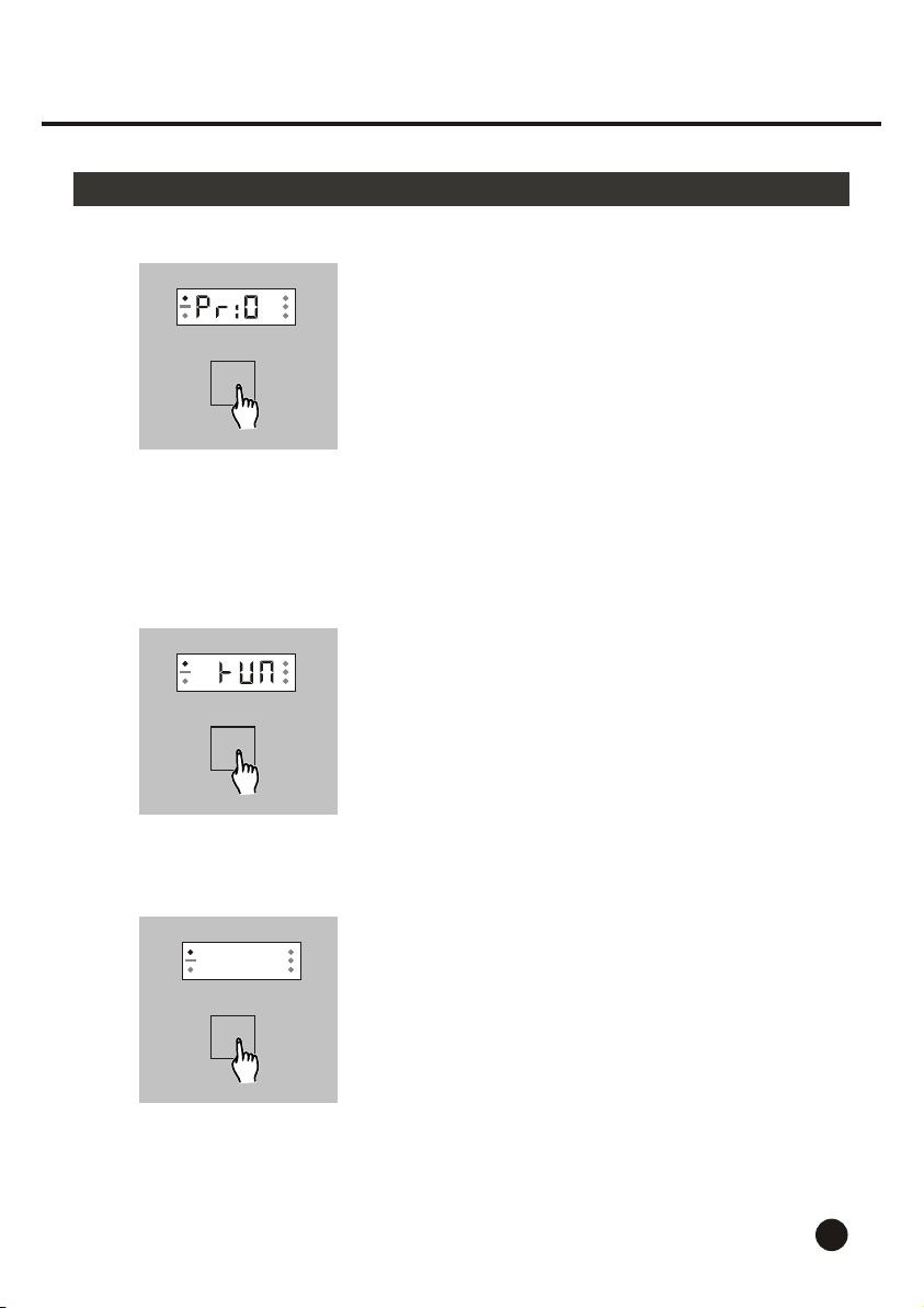
4. Once the scene is satisfactory, tap the Next
button to store the step into memory and you
are prompted to program next step.
If you want to change last step, tap the Last
button and set the scene again.
5. Repeat step 3 and 4 until you've programmed
the desired steps(up to 16 steps).
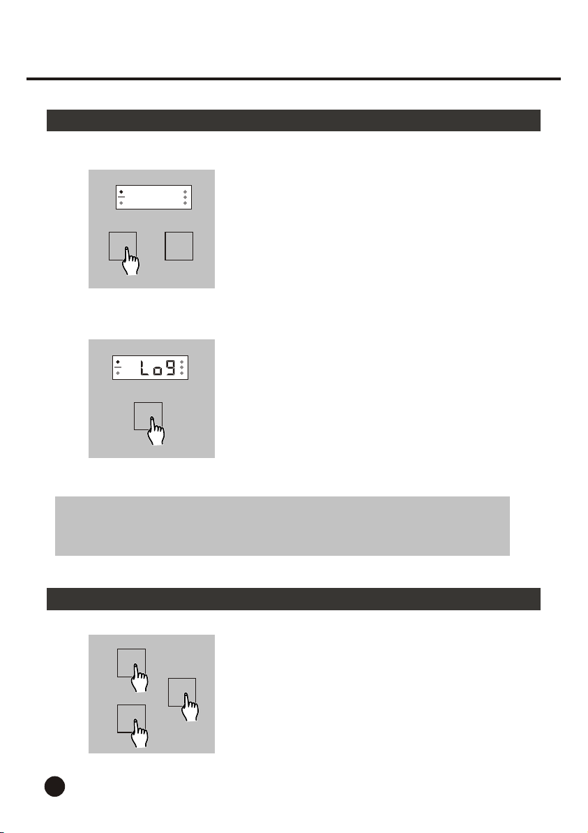
6. Tap the Program button causing the
programmed pattern to chase, the Segment
Display shows "RUN".
Tap the Program button a second time to
re-program the chase pattern.
03:00
SPEED
7. Tap the Speed button, the Segment Display
shows the current chasing speed indicated
by three or four numbers.
If the Segment Display shows three digits,
the speed is in second cycle.
For example: 3:00 indicates 3 seconds.
If the Segment Display shows four digits,
the speed is in minute cycle.
For example: 03:00 indicates 3 minutes.
14
Page 17
2. Operation Guide
2.2.8 Program Mode
3:00
speed from 0.10 second to 10 minutes.
Each tap will change the speed once, and
8. Tap the Up or Down button to change the
OR
UP DOWN
pressing and holding down will change the
speed quickly.
9. Tap the Exit button to exit from the Program
mode.
EXIT
NOTE:
When Program mode is active, other function modes, such as Pattern, Audio,
Logic and DMX modes will be disabled unless deactivation of Program.
2.2.9 Clear Memory
8
LATCH
5
FLASH
15
To clear all your memory, press and hold down
Latch 8, Flash 5 and Page buttons at a time while
turning the main power on.
PAGE
Page 18
Technical Specifications
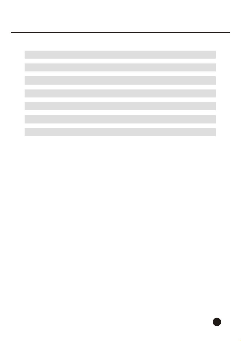
Power Input .............................................................. 9V-12V DC, 500 mA min.
DMX OUT ................................................................ 3-pin XLR female socket
DMX IN ....................................................................... 3-pin XLR male socket
Built-in Patterns ..............................................................................16 patterns
Memory Time ............................................................................ Over 10 years
Dimensions ............................................................................ 482x44x102mm
Weight ................................................................................................... 1.3 Kg
16
Page 19
ALL RIGHTS RESERVED
Rev 1.0 Jul., 2000
American DJ
C
American DJ Supply - www.americandj.com
R
24-004-0359
R
Page 20
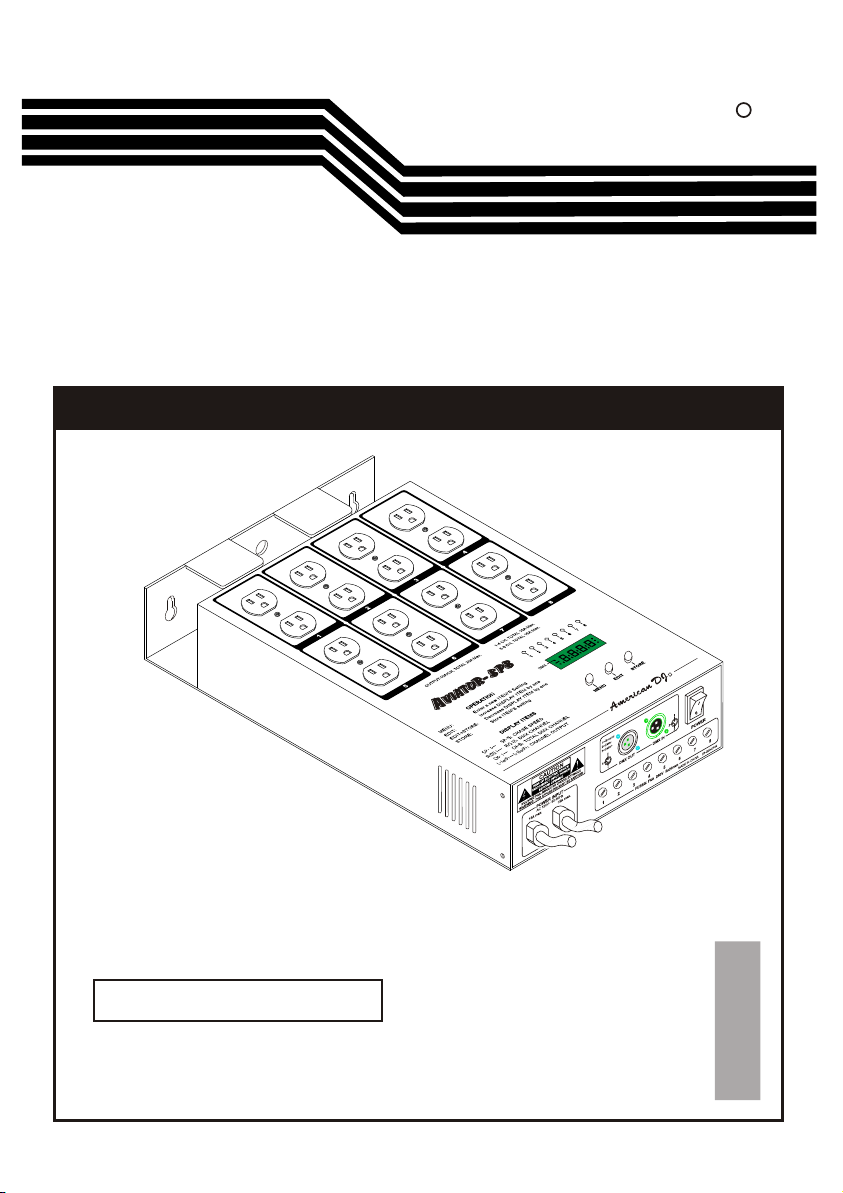
AVIATOR-SP8
USER'S MANUAL
American DJ
R
R
Please read before use
English
Page 21

Contents
Features 1
General Instructions 2
1. Overview 3
1.1 Front Panel 3
1.2 Rear Panel 4
2. Operation Guide 5
2.1 Self Test Mode 5
2.2 DMX Mode 7
Technical Specifications 11
American DJ
R
AVIATOR-SP8AVIATOR-SP8
Improvement and changes to
this manual, specifications
and design, may be made at
any time without prior notice.
ALL RIGHTS RESERVED.
American DJ
Los Angeles, CA 90058 USA
R
Page 22
Features
Thank you for purchasing this American DJ product.
This Aviator-SP8 features include:
3-pin standard DMX IN/OUT ports.
Linkup for synchronous control using DMX 512.
Serves as 1, 2, 4, and 8 dimmer pack depending on your setting
Allows individual channel Full On regardless of DMX signal
Power failure memory.
4 digits Segment Display shows current activity
and function state.
Every effort has been made to design dependability, reliability and
comfort into each unit. New products are being designed constantly
to meet the needs of both entertainment and the lighting industry.
We welcome your comments about our product and services.
It is both a privilege and a pleasure serving you.
1
Page 23
General Instructions
Please read through this operating instructions before installing or using
your new product. After you have finished reading the instructions, put
them away in a safe place for future reference.
Safe and Efficient Use
This product must be earthed.
Do not make any inflammable liquids, water or metal objects
enter the unit.
Take care not to damage the power cord.
No user serviceable parts inside, always consult authorized
personnel for repairs.
In the event of a malfunction(burning smell, etc.), immediately
stop operation, disconnect the power supply plug, and consult
authorized service personnel.
To prevent fire or shock hazard, do not expose this product to
rain or moisture.
Product Care
This product is intended for indoor use only.
Please unpack and inspect this unit for any damage. If in doubt,
don't use it and contact your local dealer.
Provide occasional ventilation during use.
Unplug the power plug from the sockets when not using the
unit for extended period.
Do not use the unit in places subject to excessive humidity,
vibration or bumps.
Do not dismantle or modify the unit.
2
Page 24
1. Overview
1.1 Front Panel
1
1 2 3 4
5 6 7 8
AVIATOR - S P8
OPERATION
MENU:
Enter a new ITEM'S Setting
EDIT:
Increase DISPLAY ITEM by one
EDIT+STORE:
Decrease DISPLAY ITEM by one
STORE:
Store ITEM'S setting
DISPLAY ITEMS
CHASE SPEED
SP-9:
DMX CHANNEL
TOTAL DMX CHANNEL
CH-8:
( ) ( )
CHANNEL OUTPUT
American DJ
1-4 CH, TOTAL 15A Max.OUTPUT:10A/CH, TOTAL 30A Max.
5-8 CH, TOTAL 15A Max.
1 2 3 4 5 6 7 8
DMX
MENU
EDIT
R
STORE
2
3
6
5
4
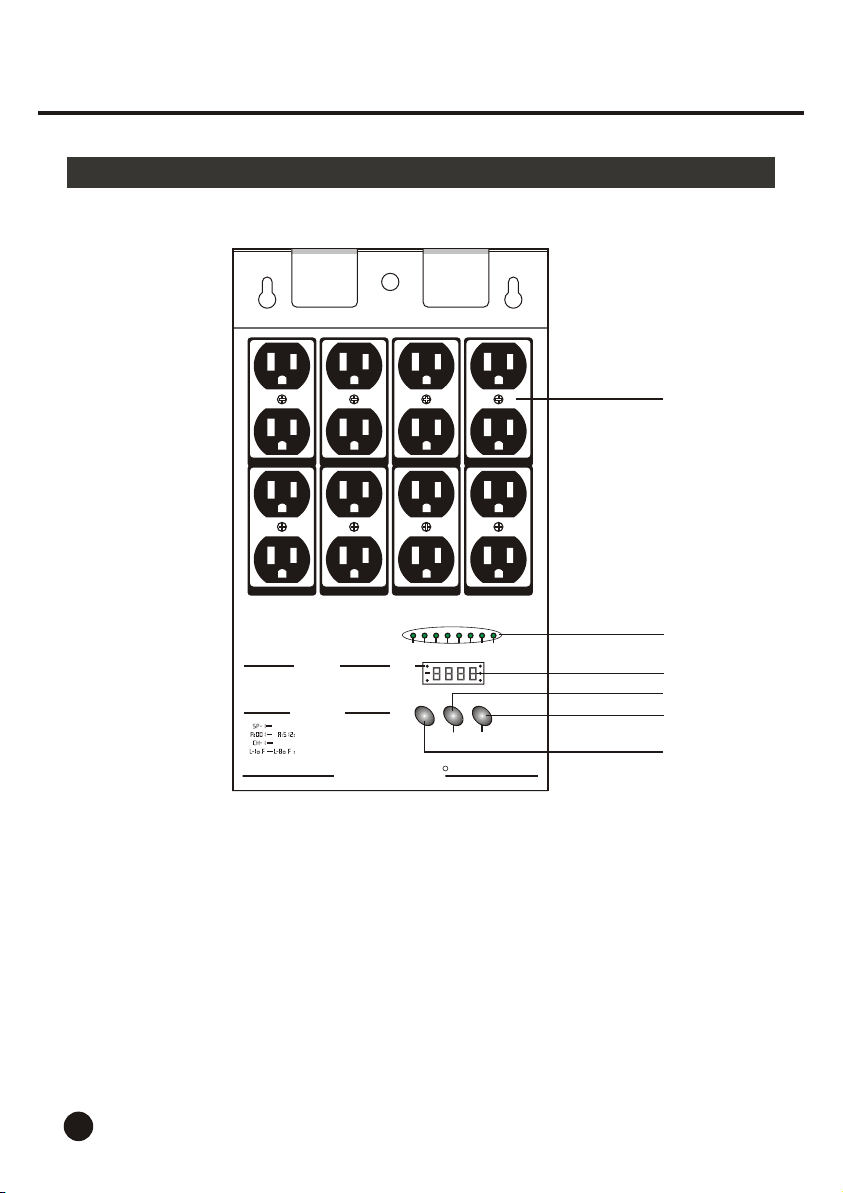
1. Channel Output 10 A per channel, total 30 A max.
1-4 CH., Total 15 A max., 5-8 CH., Total 15 A max.
2. Channel LEDs Shows the intensity of the channel in use.
3. Segment Display Shows the current activity or function state.
4. Menu button Press to enter next level.
5. Edit button Used to increase the display value in Segment Display.
Each tap changes the value once. Pressing and holding
down will increase quickly.
6. Store button Stores your settings or when used with Edit button,
decreases the display value.
3
Page 25
1. Overview
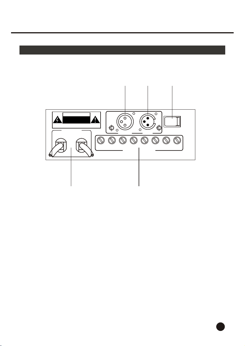
1.2 Rear Panel
3 4 5
CAUTION
RISK OF ELECTRIC SHOCK
DISCONNECT INPUT POWER
BEFORE OPENING
N'OUVREZ PAS..RISQUE DE CHOCELECTRIQUE
WARNING: THIS APPARATUS MUST BE EARTHED
POWER INPUT
AC 120V~ 50-60Hz
15A max. 15A max.
1-4 CH main control
5-8 CH
1=Ground
2=Data3=Data+
2
3
1
DMX OUT
1
3
2
FUSES: F6A 250V 5x20mm
4
DMX IN
5
1
3
POWER
2
8
7
6
1 2
1.
Power Cords Plug these cords into a matching power outlet.
2. Channel Fuse F6A 250V 5x20mm
3. DMX Output This connector sends your DMX input signal
through to the next DMX device.
4. DMX Input This connector receives your DMX input signal.
5. Power Switch This switch controls the unit's main power.
4
Page 26
2. Operation Guide
General
The Aviator-SP8 is a 8 channel DMX switch pack, consisting of a Segment
Display and several push buttons that can be used easily. The Aviator-SP8
is controlled via a standard DMX controller, which allows you to control
special affect lighting.
The Aviator-SP8 has two different operating modes: Self Test mode and DMX
mode. Please follow the instructions below to operate the unit in your desired
mode.
2.1 Self Test Mode
112233445566778
DMX
s p - 2
MENU
DMX
s p - 5
MENU
5
EDIT
EDIT
STORE
STORE
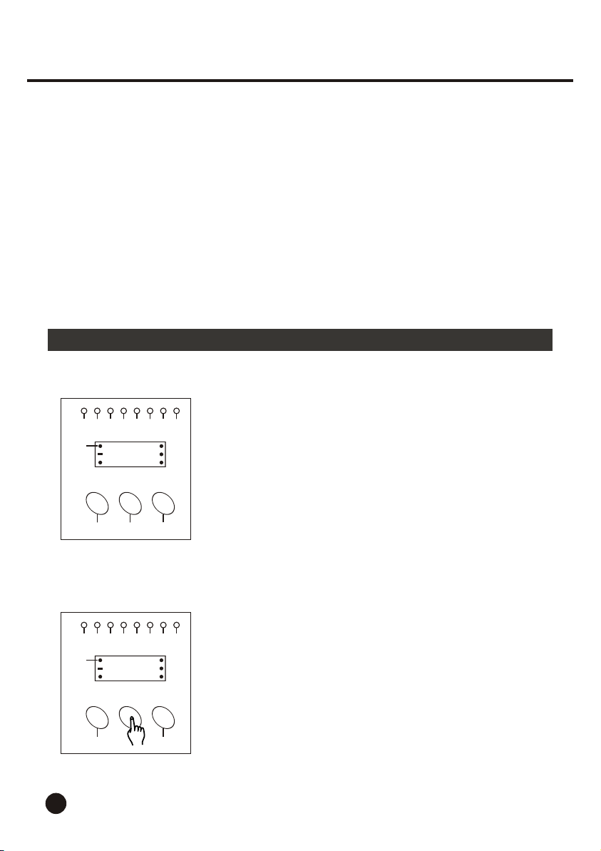
1. Turn on the power of the unit, the Segment Display
will show the self test speed of last time.
Self test speed is indicated by "SP" followed by
numbers 1-9. A value of 1 will give the slowest
speed, and the value of 9 will give the fastest speed.
8
2. Tap the Edit button to increase the speed. Each tap
will change the speed once. Pressing and holding
down the Edit button will increase the speed quickly.
Page 27
2. Operation Guide
2.1 Self Test Mode
112233445566778
DMX
s p - 4
MENU
EDIT
DMX
s p - 3
MENU
EDIT
STORE
STORE
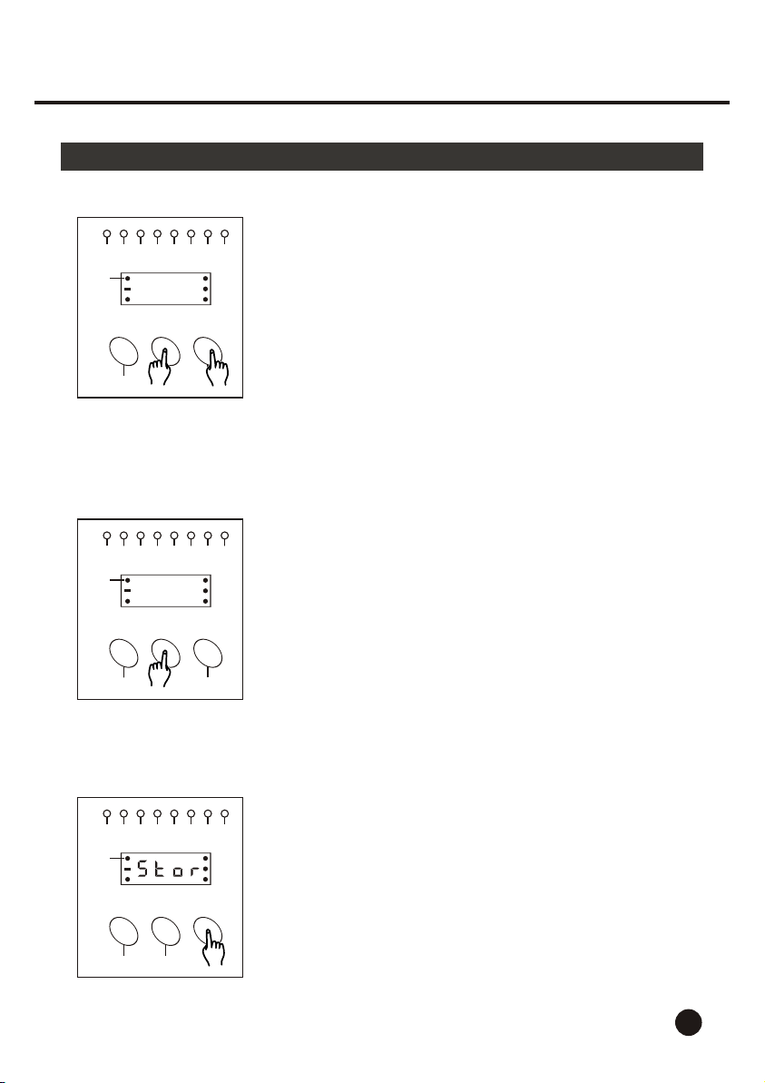
3. While pressing and holding down the Edit button,
tap the Store button, the speed will be decreased
by one.
(If you tap the Store button a second time while
pressing and holding down the Edit button, the
speed will be increase by one.)
8
4. Tap the Edit button to decrease the speed.
Pressing and holding down the Edit button
will decrease the speed quickly.
1 2 3 4 5 6 7 8
DMX
MENU
EDIT
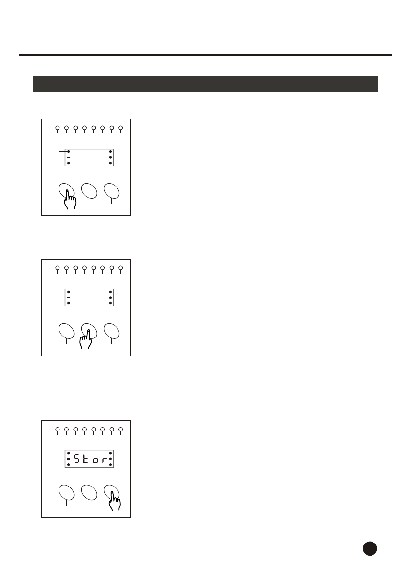
5. Tap the Store button to store the speed you've
set, the Segment Display shows " Stor " appro.
2 seconds.
STORE
6
Page 28
2. Operation Guide
2.2 DMX Mode
1 2 3 4 5 6 7 8
DMX
A 0 3 5
MENU
EDIT
1 2 3 4 5 6 7 8
DMX
A 0 5 3
MENU
EDIT
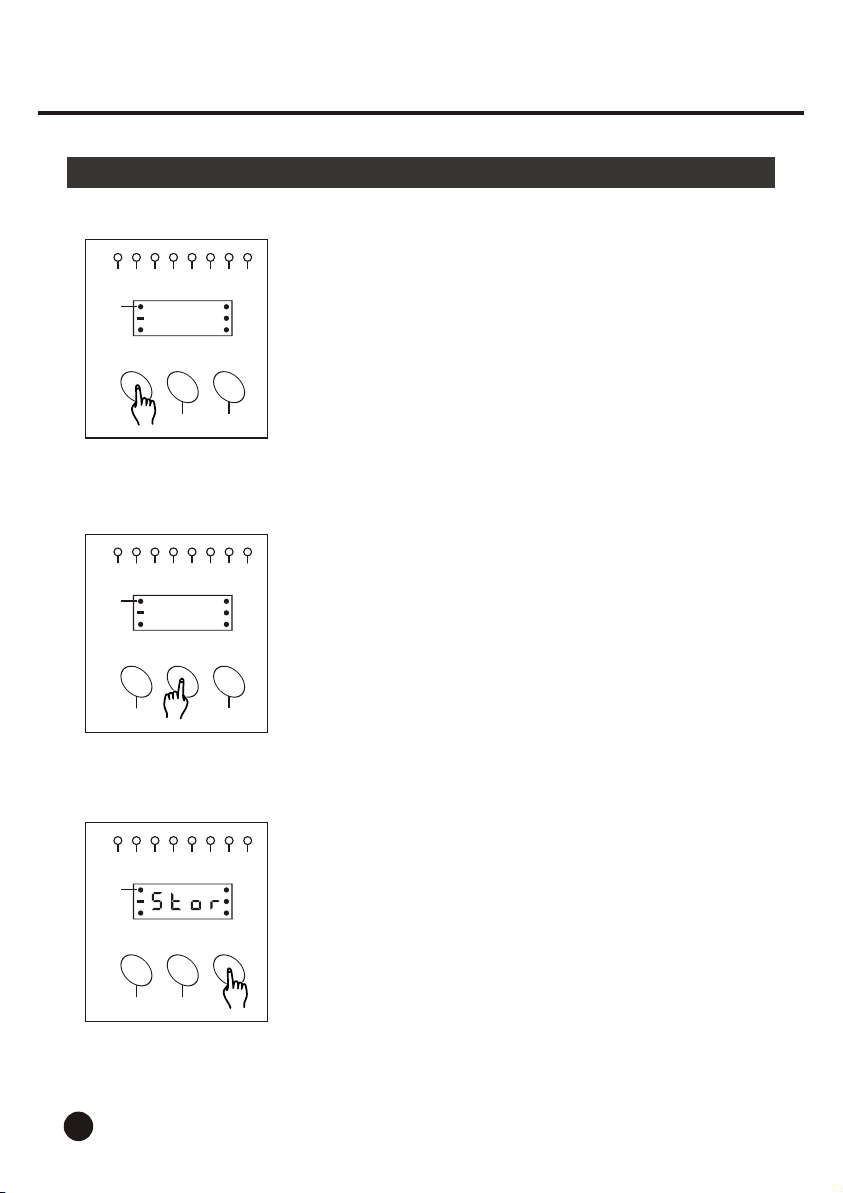
1. Tap the Menu button to enter next level, the Segment
Display shows the DMX address of last time.
The DMX address is indicated by "A" followed by three
numbers and tells the DMX controller what channel to
activate the pack's functions.
STORE
2. Follow the instructions of step 2 and 3 in Self Test Mode
to select desired DMX address.
STORE
1 2 3 4 5 6 7 8
DMX
MENU
7
EDIT
3. Tap the Store button to store the DMX address, the
Segment Display shows " Stor " appro. 2 seconds.
STORE
Page 29
2. Operation Guide
2.2 DMX Mode
1 2 3 4 5 6 7 8
DMX
c h - 4
MENU
EDIT
1 2 3 4 5 6 7 8
DMX
c h - 8
MENU
EDIT
STORE
STORE
4. Tap the Menu button to enter next level, the Segment
Display shows the " CH-" followed by any one number
from 1, 2, 4 and 8.
This functions allows you to set your dimmer pack to
serve as 1,2,4 and 8 channel DMX pack
5. Tap the Edit button to select desired channel function
from 1, 2, 4 and 8.
a. When "CH-1" appears, all 8 channel is controlled
by one DMX channel.
b. When "CH-2" appears, every four channel (CH. 1-4,
and CH.5-8) is controlled by one DMX channel.
c. When "CH-4" appears, every two channel( CH. 1-2,
CH. 3-4, CH. 5-6 and CH.7-8) is controlled by one
DMX channel.
d. When "CH-8" appears, each channel is controlled
by one DMX channel.
1 2 3 4 5 6 7 8
DMX
MENU
EDIT
6. Tap the Store button to store the channel function, the
Segment Display shows " Stor " appro. 2 seconds and
then returns to channel function.
STORE
8
Page 30
2. Operation Guide
2.2 DMX Mode
1 2 3 4 5 6 7 8
DMX
MENU
EDIT
1 2 3 4 5 6 7 8
DMX
MENU
EDIT
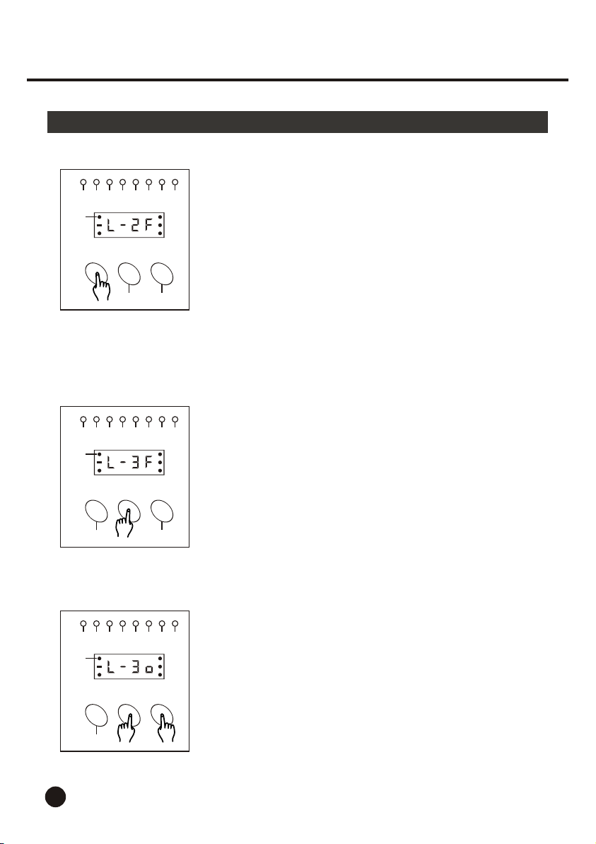
7. Tap the Menu button to enter next level, the Segment
Display shows the current state (OFF / FULL ON) of
relevant channel output
STORE
8. Tap the Edit button to select desired channel from
channels 1-8.
STORE
1 2 3 4 5 6 7 8
DMX
MENU
9
EDIT
STORE
9. While pressing and holding down the Edit button tap
the Store button to change channel state between
Off and Full On. Each tap changes the state once.
When the channel is "Off", the Segment Display
shows "o" in the fourth character and the channel is
controlled by the DMX signals.
When the channel is "Full On", the Segment Display
shows " F" in the fourth character and the channel
lights at full intensity regardless of the DMX signals.
Page 31
2. Operation Guide
2.2 DMX Mode
1 2 3 4 5 6 7 8
DMX
MENU
EDIT
1 2 3 4 5 6 7 8
DMX
s p - 3
MENU
EDIT
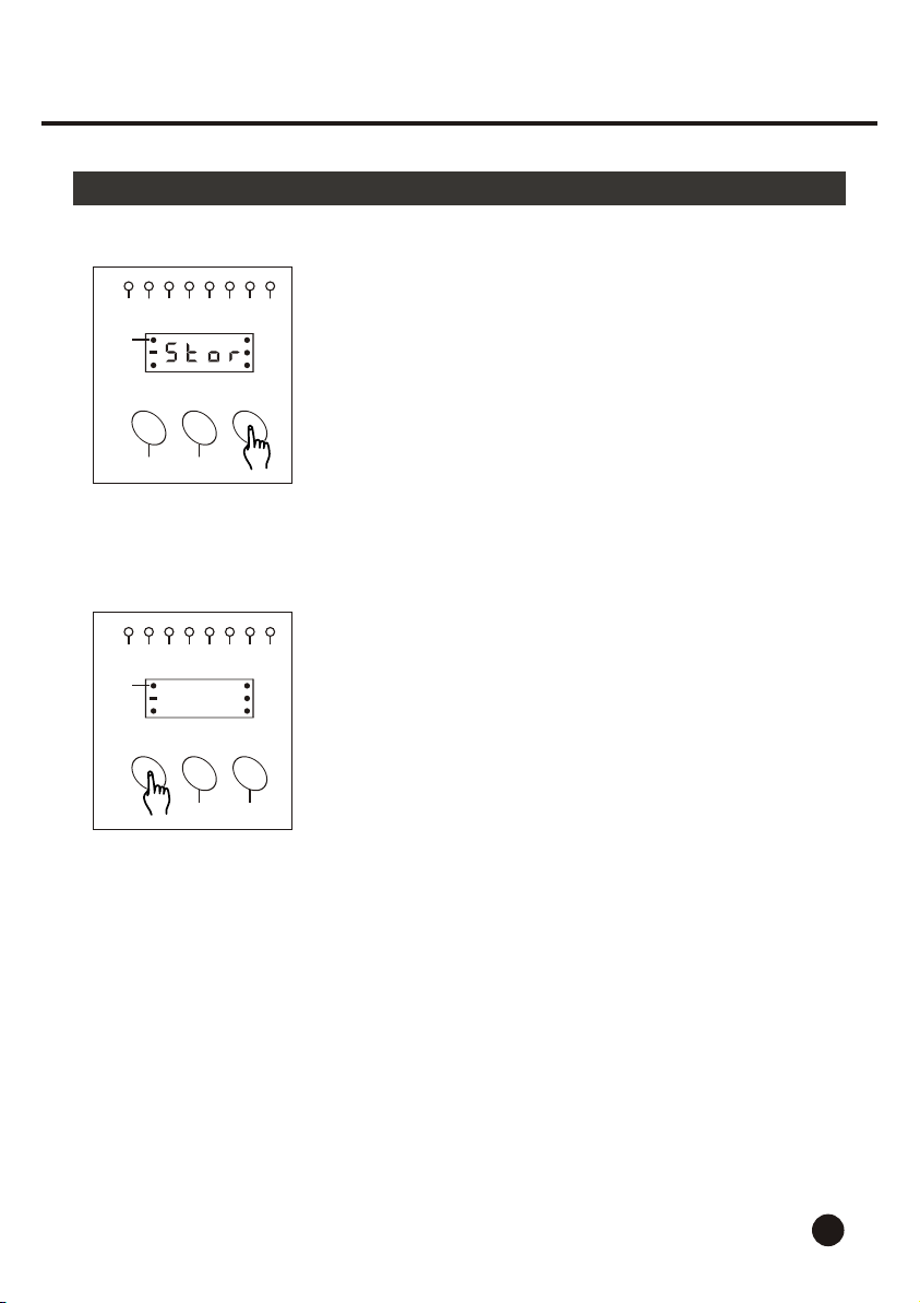
10.Tap the Store button to store the state of channel,
the Segment Display shows " Stor " appro. 2 seconds
and then returns to the state of channel.
STORE
11. Tap the Menu button, this unit will return to Self Test
mode, the Segment Display will show the speed
you've set.
STORE
10
Page 32
Technical Specifications
Power Input .......................................................................... AC 120V~50-60Hz
Channel Output ............................................. 10 A per channel, Total 30 A max.
1-4 CH., Total 15 A max., 5-8 CH., Total 15 A max.
DMX OUT .................................................................. 3-pin XLR female socket
DMX IN ......................................................................... 3-pin XLR male socket
Channel Fuse ...................................................................... F6A 250V 5x20mm
Dimensions ............................................................................... 330x192x65mm
Weight ...................................................................................................... 3.6 Kg
11
Page 33
ALL RIGHTS RESERVED
American DJ
R
24-004-0384
Rev 1.1 Jul., 2000
C
American DJ Supply - www.americandj.com
R
 Loading...