

Page 1
18P HEX IP
User Instructions
Page 2
©2018 ADJ Products, LLC all rights reserved. Information, specications, diagrams, images, and
instructions herein are subject to change without notice. ADJ Products, LLC logo and identifying
product names and numbers herein are trademarks of ADJ Products, LLC. Copyright protection
claimed includes all forms and matters of copyrightable materials and information now allowed by
statutory or judicial law or hereinafter granted. Product names used in this document may be
trademarks or registered trademarks of their respective companies and are hereby acknowledged.
All non-ADJ Products, LLC brands and product names are trademarks or registered trademarks of
their respective companies.
ADJ Products, LLC and all aliated companies hereby disclaim any and all liabilities for property,
equipment, building, and electrical damages, injuries to any persons, and direct or indirect economic
loss associated with the use or reliance of any information contained within this document, and/or as
a result of the improper, unsafe, unsucient and negligent assembly, installation, rigging, and operation of this product.
DOCUMENT VERSION
Please check www.adj.com for the latest revision/update of this guide.
Date
5/25/18
6/13/18
Document
Version
1 1.04
1.2 1.05
Software
Version
>
DMX
Channel
Mode
6/7/8/13 Initial Release
6/7/8/13 Updated Color Macros
Notes
Europe Energy Saving Notice
Energy Saving Matters (EuP 2009/125/EC)
Saving electric energy is a key to help protecting the enviroment. Please turn o all electrical products when they are not in use. To avoid power consumption in idle mode, disconnect all electrical
equipment from power when not in use. Thank you!
Page 3
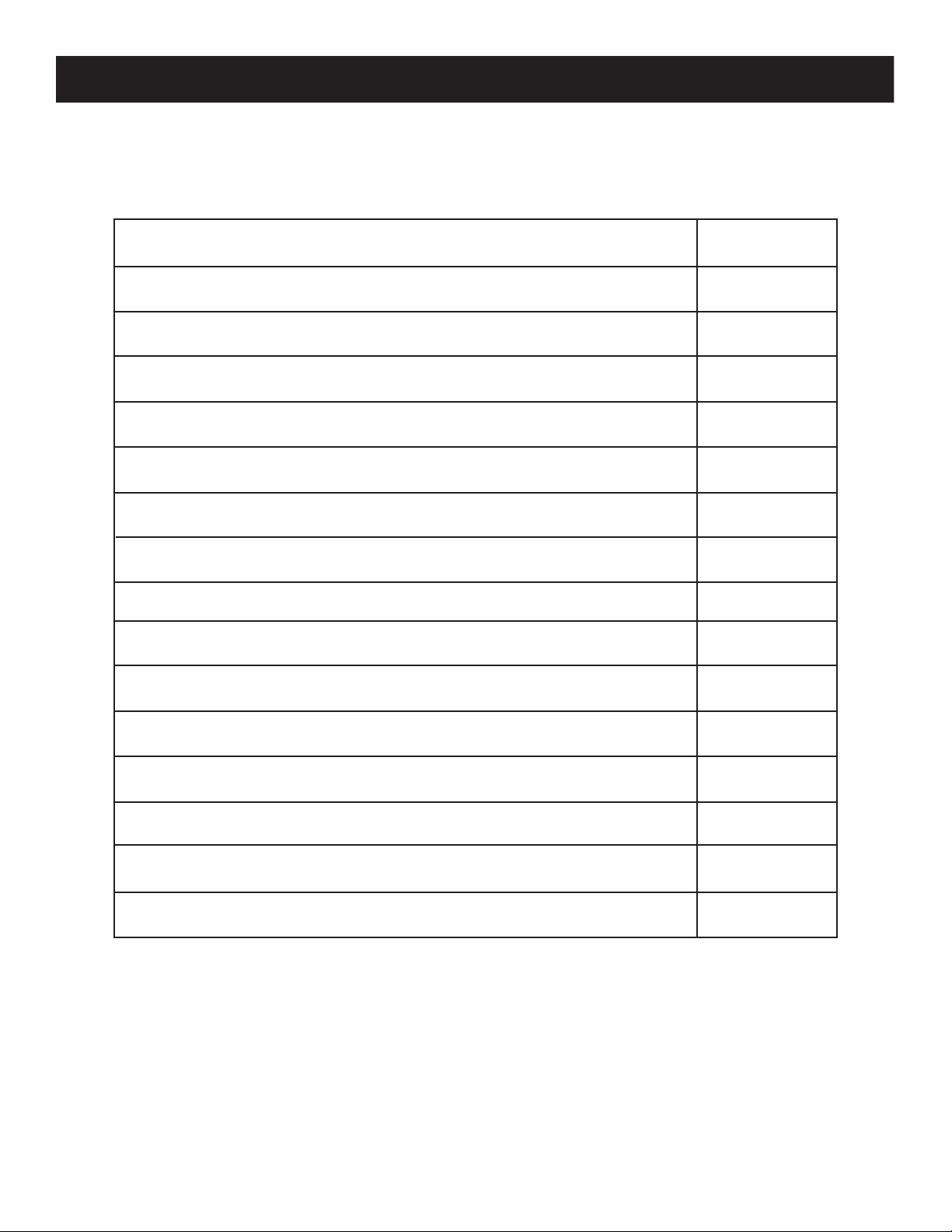
18P Hex IP Table of Contents
Introduction
F e a t u r e s / W a r r a n t y R e g i s t r a t i o n / I n s t a l l a t i o n
Safety Precautions
IP Notice
Layout
DMX Set Up
DMX Addressing
DMX Channel Modes
Color Macro Chart
System Menu
Operating Instructions
3
4
5
7
8
9
11
12
13
15
17
Dimmer Curve Chart
Dimensional Drawings
Power Linking/Trouble Shooting/Cleaning
Warranty
Technical Specications
ADJ Products, LLC - www.adj.com - 18P Hex IP User Manual Page 2
21
22
23
24
25
Page 4

18P Hex IP Introduction
Unpacking: Thank you for purchasing the 18P Hex IP by ADJ Products, LLC. Every 18P Hex IP has
been thoroughly tested and has been shipped in perfect operating condition. Carefully check the shipping carton for damage that may have occurred during shipping. If the carton appears to be damaged,
carefully inspect your xture for any damage and be sure all accessories necessary to operate the unit
has arrived intact. In the case damage has been found or parts are missing, please contact our toll free
customer support number for further instructions. Do not return this unit to your dealer without rst
contacting customer support.
Introduction: The 18P Hex IP is a DMX intelligent, IP rated LED par fixture. This xture can be used in
a stand alone mode or connected in a Master/Slave conguration. This par has five operating modes:
RGBWA + UV dimmer mode, Static Color mode, Auto Run mode, Color Macro mode, and DMX control.
The 7P Hex IP has 4 DMX channel modes; 6, 7, 8, & 13.
Customer Support: ADJ Products, LLC provides a customer support line, to provide set up help and
to answer any question should you encounter problems during your set up or initial operation. You
may also visit us on the web at www.adj.com for any comments or suggestions. Service Hours are
Monday through Friday 8:00 a.m. to 4:30 p.m. Pacic Standard Time.
Voice: (323) 582-2650
Fax: (323) 582-2941
E-mail: support@americandj.com
Caution! There are no user serviceable parts inside this unit. Do not attempt any repairs yourself,
doing so will void your manufactures warranty. In the unlikely event your unit may require service
please contact ADJ Products, LLC.
PLEASE recycle the shipping carton when ever possible.
ADJ Products, LLC - www.adj.com - 18P Hex IP User Manual Page 3
Page 5

18P Hex IP Features
• Multi-Colors
• Five Operating Modes
• Electronic Dimming 0-100%
• DMX-512 protocol
• 3-Pin DMX Connection
• Four DMX Modes: 6 Channel Mode, 7 Channel Mode, 8 Channel Mode, and 13 Channel Mode.
• Multiple Unit Power Linking (See page 23)
Included:
1 x Seetronic Power Cable
18P Hex IP Warranty Registration
The 18P Hex IP carries a 2 year limited warranty. Please fill out the enclosed warranty card to validate
your purchase. All returned service items whether under warranty or not, must be freight pre-paid and
accompany a return authorization (R.A.) number. The R.A. number must be clearly written on the out-
side of the return package. A brief description of the problem as well as the R.A. number must also
be written down on a piece of paper included in the shipping carton. If the unit is under warranty, you
must provide a copy of your proof of purchase invoice. You may obtain a R.A. number by contacting
our customer support team on our customer support number. All packages returned to the service
department not displaying a R.A. number on the outside of the package will be returned to the ship-
per.
18P Hex IP Installation
The unit should be mounted using a mounting clamp (not provided), axing it to the mounting
bracket that is provided with the unit. Always ensure that the unit is rmly xed to avoid vibration
and slipping while operating. Always ensure that the structure to which you are attaching the unit is
secure and is able to support a weight of 10 times the unit’s weight. Also, always use a safety cable
that can hold 12 times the weight of the unit when installing the xture.
The equipment must be installed by a professional, and it must be installed in a place where it is out
of the reach of people’s grasp.
Ensure ALL connections and end caps are properly sealed with a non-conductive dielectric
grease (available at most electrical suppliers) to prevent water ingress/condensation and/or
corrosion.
ADJ Products, LLC - www.adj.com - 18P Hex IP User Manual Page 4
Page 6

18P Hex IP Safety Precautions
• Do not attempt to operate this unit if the power cord has been frayed or broken. Do not attempt to
remove or break o the ground prong from the electrical cord. This prong is used to reduce the risk
of electrical shock and re in case of an internal short.
• Disconnect from main power before making any type of connection.
• Do not remove the cover under any conditions. There are no user serviceable parts inside.
• Never operate this unit when it’s cover is removed.
• Never plug this unit in to a dimmer pack
• Always be sure to mount this unit in an area that will allow proper ventilation. Allow about 6”
(15cm) between this device and a wall.
• Do not attempt to operate this unit, if it becomes damaged.
• During long periods of non-use, disconnect the unit’s main power.
• Always mount this unit in safe and stable matter.
• Power-supply cords should be routed so that they are not likely to be walked on or pinched by
items placed upon or against them, paying particular attention to the point they exit from the unit.
• Cleaning -The fixture should be cleaned only as recommended by the manufacturer. See page 23
for cleaning details.
• Heat -The appliance should be situated away from heat sources such as radiators, heat registers,
stoves, or other appliances (including amplifiers) that produce heat.
• The fixture should be serviced by qualified service personnel when:
A. The power-supply cord or the plug has been damaged.
B. Objects have fallen, or liquid has been spilled into the fixture.
C. The fixture does not appear to operate normally or exhibits a marked change in performance.
D. The fixture has fallen and/or subjected to extreme handling.
ADJ Products, LLC - www.adj.com - 18P Hex IP User Manual Page 5
Page 7

18P Hex IP Safety Precautions
RISK GROUP 3 - RISK OF EXPOSURE TO ULTRAVIOLET (UV) RADIATION!
FIXTURE EMITS HIGH INTENSITY ULTRAVIOLET (UV) LIGHT FROM THE UV LED.
WEAR PROPER EYE AND SKIN PROTECTION.
AVOID PROLONGED PERIODS OF EXPOSURE TO THE UV LED.
AVOID WEARING WHITE COLOR CLOTHING AND/OR USING (UV) PAINTS ON SKIN.
AVOID DIRECT EYE AND/OR SKIN EXPOSURE AT DISTANCES SHORTER THAN 11 feet (3.3m).
DO NOT OPERATE FIXTURE WITH DAMAGED OR MISSING EXTERNAL COVER.
DO NOT LOOK DIRECTLY INTO THE (UV) LIGHT AND/OR VIEW (UV) LIGHT DIRECTLY WITH
OPTICAL INSTRUMENTS THAT MAY CONCENTRATE THE LIGHT/RADIATION OUTPUT.
INDIVIDUALS SUFFERING FROM A RANGE OF EYE CONDITIONS, SUNLIGHT EXPOSURE
DISORDERS, OR INDIVIDUALS USING PHOTOSENSITIVE MEDICATION, MAY RECEIVE
DISCOMFORT IF EXPOSED TO THE ULTRAVIOLET (UV) LIGHT EMITTED FROM THIS FIXTURE.
ADJ Products, LLC - www.adj.com - 18P Hex IP User Manual Page 6
Page 8
18P Hex IP IP Notice
IP65 RATED
An IP rated lighting fixture is one, which is commonly installed in
outdoor environments and has been designed with an enclosure
that effectively water. The International Protection (IP) rating
system is commonly expressed as "IP" (Ingress Protection) followed
by two numbers (i.e. IP65) where the numbers define the degree
of protection. The first digit (Foreign Bodies Protection) indicates
the extent of protection against particles entering the fixture and
the second digit (Water Protection) indicates the extent of
protection against water entering the fixture. An IP65 rated
lighting fixture is one, which has been designed and tested to
protect against the ingress of dust (6) and high-pressure water jets
from any direction (5).
MARINE/COASTAL ENVIRONMENT INSTALLATIONS!
Please note although this fixture is IP rated, the fixture is NOT
suitable for marine and/or coastal environment installations.
Installing this fixture in a marine and/or coastal environment may
cause corrosion and/or excessive wear to the interior and/or
exterior components of the fixture. Damages and/or
performance issues resulting from installation in a marine and/or
coastal environment will void the manufactures warranty and will
NOT be subject to any warranty claims and/or repairs.
OPTIONAL CORROSION- RESISTANT COATING
Optional Corrosion-Resistant Coatings may be available for this
fixture. Please consult your ADJ Products, LLC sales representative
for details.
ADJ Products, LLC - www.adj.com - 18P Hex IP User Manual Page 7
Page 9

18P Hex IP Layout
LCD Screen
Mode Button
Up Button
Down Button
Enter Button
Seetronic In Port
Seetronic Out Port
3-Pin XLR Out Port
3-Pin XLR In Port
ADJ Products, LLC - www.adj.com - 18P Hex IP User Manual Page 8
Page 10

18P Hex IP DMX Set Up
REMOTE
CONTROL
INPUT
POWER
INPUT OUTPUT
SOUND
REMOTE
CONTROL
INPUT
POWER
INPUT OUTPUT
SOUND
REMOTE
CONTROL
INPUT
POWER
INPUT OUTPUT
DMX512
DMX+,DMX-,COMMON
1
2
3
Termination reduces signal errors and
avoids signal transmission problems
and interference. It is always advisable
to connect a DMX terminal, (Resistance
120 Ohm 1/4 W) between PIN 2 (DMX-)
and PIN 3 (DMX +) of the last fixture.
DMX-512: DMX is short for Digital Multiplex. This is a universal protocol used as a form of commu-
nication between intelligent fixtures and controllers. A DMX controller sends DMX data instructions
from the controller to the fixture. DMX data is sent as serial data that travels from fixture to fixture
via the DATA “IN” and DATA “OUT” XLR terminals located on all DMX fixtures (most controllers only
have a DATA “OUT” terminal).
DMX Linking: DMX is a language allowing all makes and models of dierent manufactures to be
linked together and operate from a single controller, as long as all xtures and the controller are DMX
compliant. To ensure proper DMX data transmission, when using several DMX fixtures try to use
the shortest cable path possible. The order in which fixtures are connected in a DMX line does not
influence the DMX addressing. For example; a fixture assigned a DMX address of 1 may be placed
anywhere in a DMX line, at the beginning, at the end, or anywhere in the middle. When a fixture is
assigned a DMX address of 1, the DMX controller knows to send DATA assigned to address 1 to that
unit, no matter where it is located in the DMX chain.
Data Cable (DMX Cable) Requirements (For DMX Operation): The 18P Hex IP can be controlled via
DMX-512 protocol. The 18P Hex IP has 4 DMX channel modes. The DMX address is set on the back
panel of the 18P Hex IP. Your unit and your DMX controller require a standard 3-pin XLR connector for
data input and data output (Figure 1). We recommend Accu-Cable DMX cables. If you are making your
own cables, be sure to use standard 110-120 Ohm shielded cable (This cable may
be purchased at almost all pro lighting stores). Your cables should be made with a
male and female XLR connector on either end of the cable. Also remember that
DMX cable must be daisy chained and cannot be split.
Figure 1
Notice: Be sure to follow gures two and three when making your own cables. Do not use the ground
lug on the XLR connector. Do not connect the cable’s shield conductor to the ground lug or allow the
shield conductor to come in contact with the XLR’s outer casing. Grounding the shield could cause a
short circuit and erratic behavior.
XLR Male Socket
1 Ground
Figure 3
DMX512 OT
3-PIN XLR
2 Cold
3 Hot
1
3
2
XLR Female Socket
2 Cold
COMMON
DMX +
DMX -
1 Ground
3 Hot
1
DMX512 IN
3
3-PIN XLR
2
Figure 2
XLR Pin Conguration
Pin 1 = Ground
Pin 2 = Data Compliment (negative)
Pin 3 = Data True (positive)
ADJ Products, LLC - www.adj.com - 18P Hex IP User Manual Page 9
Page 11

18P Hex IP DMX Set Up
POWER
SOUND
REMOTE
CONTROL
INPUT
POWER
INPUT OUTPUT
and PIN 3 (DMX +) of the last fixture.
Special Note: Line Termination.
When longer runs of cable are used, you may need to use a terminator on the last unit to avoid erratic behavior. A terminator is a 110-120 ohm 1/4 watt resistor which is
connected between pins 2 and 3 of a male XLR connector (DATA + and DATA -). This unit is inserted
in the female XLR connector of the last unit in your daisy chain to terminate the line. Using a cable
terminator (ADJ part number Z-DMX/T) will decrease the possibilities of erratic behavior.
Termination reduces signal errors and
1
3
avoids signal transmission problems
and interference. It is always advisable
2
to connect a DMX terminal, (Resistance
120 Ohm 1/4 W) between PIN 2 (DMX-)
Figure 4
5-Pin XLR DMX Connectors.
Some manufactures use 5-pin DMX-512 data cables for DATA transmission in place of 3-pin. 5-pin DMX xtures may be implemented in a 3-pin DMX line. When inserting
standard 5-pin data cables in to a 3-pin line a cable adaptor must be used, these adaptors are readily
available at most electric stores. The chart below details a proper cable conversion.
3-Pin XLR to 5-Pin XLR Conversion
Conductor 5-Pin XLR Male (In)3-Pin XLR Female (Out)
Ground/Shield
Data Compliment (- signal)
Data True (+ signal)
Not Used
Not Used
Pin 1
Pin 2
Pin 3
Pin 1
Pin 2
Pin 3
Do Not Use
Do Not Use
ADJ Products, LLC - www.adj.com - 18P Hex IP User Manual Page 10
Page 12

18P Hex IP DMX Addressing
All xtures should be given a DMX starting address when using a DMX controller, so the correct xture
responds to the correct control signal. This digital starting address is the channel number from which
the xture starts to “listen” to the digital control signal sent out from the DMX controller. The assignment
of this starting DMX address is achieved by setting the correct DMX address on the digital control
display on the xture.
You can set the same starting address for all xtures or a group of xtures, or set dierent addresses
for each individual xture. Setting all xtures to the same DMX address will cause all xtures to react
in the same way, in other words, changing the settings of one channel will aect all the xtures
simultaneously.
If you set each xture to a dierent DMX address, each unit will start to “listen” to the channel number
you have set, based on the quantity of DMX channels of each xture. That means changing the settings
of one channel will only aect the selected xture.
In the case of the 18P Hex IP, when in 13 channel mode you should set the starting DMX address of
the rst unit to 1, the second unit to 14 (13 + 1), the third unit to 27 (14 + 13), and so on. (See chart
below for more details.)
Channel Mode
6 channels 1 7 13 19
7 channels 1 8 15 22
8 channels 1 9 17 25
13 channels 1
Unit1
Address
Unit2
Address
14 27
Unit3
Address
Unit4
Address
40
ADJ Products, LLC - www.adj.com - 18P Hex IP User Manual Page 11
Page 13

18P Hex IP DMX Traits & Values
6CH 7CH 8CH 13CH
1 1 1 1
0 -255
Red
0~100%
2 2 2 2
3 3 3 3
4 4 4 4
5 5 5 5
6 6 6 6
7 7
7
8 8
0 - 31
32 - 63
64 - 95
96 - 127
128 - 159
160 - 191
192 - 223
224 - 255
9
0 - 255
0 -255
0 -255
0 -255
0 -255
0 -255
0 -255
Green
0~100%
Blue
0~100%
White
0~100%
Amber
0~100%
UV
0~100%
Master Dimmer
0 ~100%
Strobe
LED O
LED On
Strobe Slow - Fast
LED On
Strobe Pulse Slow - Fast
LED On
Random Strobe
LED On
Color Macro
See pages 13-14 for the Color Macro Chart
Auto Programs
No Function
Program 1
Program 2
Program 3
Program 4
Program 5
Program 6
Program 7
Program 8
Program 9
Program 10
Program 11
Program 12
Auto Program Speed
From slow to fast
Auto Program Fade
From slow to fast
10
11
12
0 - 19
20 - 39
40 - 59
60 - 79
80 - 99
100 - 119
120 - 139
140 - 159
160 - 179
180 - 199
200 - 219
220 - 239
240 - 255
0 - 255
0 - 255
Dimmer Modes
0 - 20
21- 40
13
41- 60
61- 80
81- 100
101- 255
Standard
Stage
TV
Architectural
Theatre
Default to unit setting
ADJ Products, LLC - www.adj.com - 18P Hex IP User Manual Page 12
Page 14

18P Hex IP Color Macro Chart
Color No. DMX
VALUE
Color33 129-132 255 206 143 0
Color34 133-136 254 177 153 0
Color35 137-140 254 192 138 0
Color36 141-144 254 165 98 0
Color37 145-148 254 121 0 0
Color38 149-152 176 17 0 0
Color39 153-156 96 0 11 0
Color40 157-160 234 139 171 0
Color41 161-164 224 5 97 0
Color42 165-168 175 77 173 0
Color43 169-172 119 130 199 0
Color44 173-176 147 164 212 0
Color45 177-180 88 2 163 0
Color46 181-184 0 38 86 0
Color47 185-188 0 142 208 0
Color48 189-192 52 148 209 0
Color49 193-196 0 46 35 0
Color50 197-200 8 107 222 0
Color51 201-204 107 156 231 0
Color52 205-208 165 198 247 0
Color53 209-212 0 83 115 0
Color54 213-216 0 97 166 0
Color55 217-220 1 100 167 0
Color56 221-224 0 40 86 0
Color57 225-228 209 219 182 0
Color58 229-232 42 165 85 0
Color59 233-236 255 0 0 0
Color60 237-240 0 255 0 0
Color61 241-244 0 0 255 0
Color62 245-248 0 0 0 255
Color63 249-252 0 0 0 0
Color64 253-255 0 0 0 0
Color No. DMX
VALUE
OFF 0 0 0 0 0
Color1 1-4 80 255 234 80
Color2 5-8 80 255 164 80
Color3 9-12 77 255 112 77
Color4 13-16 117 255 83 83
Color5 17-20 160 255 77 77
Color6 21-24 223 255 83 83
Color7 25-28 255 243 77 77
Color8 29-32 255 200 74 74
Color9 33-36 255 166 77 77
Color10 37-40 255 125 74 74
Color11 41-44 255 97 77 74
Color12 45-48 255 71 77 71
Color13 49-52 255 83 134 83
Color14 53-56 255 93 182 93
Color15 57-60 255 96 236 96
Color16 61-64 238 93 255 93
Color17 65-68 196 87 255 87
Color18 69-72 150 90 255 90
Color19 73-76 100 77 255 77
Color20 77-80 77 100 255 77
Color21 81-84 67 148 255 67
Color22 85-88 77 195 255 77
Color23 89-92 77 234 255 77
Color24 93-96 158 255 144 144
Color25 97-100 255 251 153 153
Color26 101-104 255 175 147 147
Color27 105-108 255 138 186 138
Color28 109-112 255 147 251 147
Color29 113-116 151 138 255 138
Color30 117-120 100 138 255 138
Color31 121-124 138 169 255 138
Color32 125-128 255 255 255 255
RED GREEN BLUE WHITE
RGBWA+UV COLOR INTENSITY
AMBER UV
0
0
0
0
0
0
0
0
0
0
0
0
0
0
0
0
0
0
0
0
0
0
0
0
0
0
0
0
0
0
0
0
0
ADJ Products, LLC - www.adj.com - 18P Hex IP User Manual Page 13
0
0
0
0
0
0
0
0
0
0
0
0
0
0
0
0
0
0
0
0
0
0
0
0
0
0
0
0
0
0
0
0
0
Page 15

18P Hex IP Color Macro Chart
Color No. DMX
VALUE
Color33 129-132 255 206 143 0
Color34 133-136 254 177 153 0
Color35 137-140 254 192 138 0
Color36 141-144 254 165 98 0
Color37 145-148 254 121 0 0
Color38 149-152 176 17 0 0
Color39 153-156 96 0 11 0
Color40 157-160 234 139 171 0
Color41 161-164 224 5 97 0
Color42 165-168 175 77 173 0
Color43 169-172 119 130 199 0
Color44 173-176 147 164 212 0
Color45 177-180 88 2 163 0
Color46 181-184 0 38 86 0
Color47 185-188 0 142 208 0
Color48 189-192 52 148 209 0
Color49 193-196 0 46 35 0
Color50 197-200 8 107 222 0
Color51 201-204 107 156 231 0
Color52 205-208 165 198 247 0
Color53 209-212 0 83 115 0
Color54 213-216 0 97 166 0
Color55 217-220 1 100 167 0
Color56 221-224 0 40 86 0
Color57 225-228 209 219 182 0
Color58 229-232 42 165 85 0
Color59 233-236 255 0 0 0
Color60 237-240 0 255 0 0
Color61 241-244 0 0 255 0
Color62 245-248 0 0 0 255
Color63 249-252 0 0 0 0
Color64 253-255 0 0 0 0
RED GREEN BLUE WHITE
RGBWA+UV COLOR INTENSITY
AMBER UV
0
0
0
0
0
0
0
0
0
0
0
0
0
0
0
0
0
0
0
0
0
0
0
0
0
0
0
0
0
0
255
0
0
0
0
0
0
0
0
0
0
0
0
0
0
0
0
0
0
0
0
0
0
0
0
0
0
0
0
0
0
0
0
255
ADJ Products, LLC - www.adj.com - 18P Hex IP User Manual Page 14
Page 16

18P Hex IP System Menu
1. STATC
ON/OFF
MENU SUB MENU OPTIONS/VALUES (DEFAULT SHADED) DESCRIPTION
Display
Menu
Menu
Set ADDR
Menu
User Mode
Menu
Function
Update Wait…
ADJ
V1.03
Set ADDR
001
CH06
DimCurve
Standard
NO DMX
Hold
AUTO RUN
FQN:01
CL:R
Macros
00
LCD.Set
001 -506
6/7/8/13
Standard
/Stage/TV Architec /Theatre
Hold /Blackout / Program
01~99
R/G/B/RG/GB/RB/RGB/BLAC
STR 000-255
00 ~63
Backlight
Key Lock
05~60m
ON/ON1/OFF
DisFlash
DMX Addressing
/
DMX Channel Modes
Dimmer Curve Setting
DMX Lost Setting
Auto Run Programs
Static Color Mode
Color Macro Mode
LCD Display Settings
DFSET
OFF
TEMP
Fahren
Settings
WhiteBal
ON/OFF
Fahren
Celsius
Red:000~255
Green:000~255
Blue:000~255
White:000~255
Default Reset
Temperature Display
Setting
White Balance Setting
Amber:000~255
UV:000~255
Fre_hz
900
Gamma
2.0
900 /1000/1100/1200/1300/1400/1500/2500/4000/50
00/10k /15k /20k /25k
2.0 / 2.2 / 2.4 / 2.8
Set LED Refresh
Frequency Rate
Set Gamma Brightness
ADJ Products, LLC - www.adj.com - 18P Hex IP User Manual Page 15
Page 17

CH06
DimCurve
Standard
Standard
/Stage/TV Architec /Theatre
NO DMX
Hold
Hold /Blackout / Program
AUTO RUN
FQN:01
01~99
1. STATC
CL:R
R/G/B/RG/GB/RB/RGB/BLAC
STR 000-255
Macros
00
00 ~63
LCD.Set
Backlight
Key Lock
05~60m
ON/ON1/OFF
DisFlash
ON/OFF
DFSET
OFF
ON/OFF
TEMP
Fahren
Fahren
Celsius
Settings
WhiteBal
Red:000~255
Green:000~255
Blue:000~255
White:000~255
Amber:000~255
UV:000~255
White Balance Setting
Fre_hz
900
900 /1000/1100/1200/1300/1400/1500/2500/4000/50
00/10k /15k /20k /25k
Gamma
2.0
2.0 / 2.2 / 2.4 / 2.8
User Mode
Menu
Function
Default Reset
/
Dimmer Curve Setting
DMX Lost Setting
Auto Run Programs
Static Color Mode
Color Macro Mode
Temperature Display
Setting
LCD Display Settings
Set Gamma Brightness
Set LED Refresh
Frequency Rate
18P Hex IP System Menu
Menu
Info
Menu
Slave
Menu
Manual
Info
TimeInfo
Info
TempInfo
Info
Model Inf
Info
Software
Info
ErrorInf
Slave
ManCtrl Dimmer 000~
ManCtrl Red 000~255
ManCtrl Green 000~255
ManCtrl Blue 000~255
ManCtrl White 000~255
TimeInfo Current
TimeInfo TotalTim
TimeInfo LastClea
TimeInfo TimerPIN
TempInfo
XXX
V1.03
None
255
Current Running Time (Hours)
Total Time (Hours)
Last Time The Running Time
Was Cleared (Hours)
Clear 0 Password:
(Password=050)
Total Time Clear 0:
(Password=060)
Current Running
Temperature
Model Name
Current Software Version
Error Information
Slave Setting
Manual Control
ManCtrl Amber 000~255
ManCtrl Purple 000~255
ManCtrl Strobe 000~255
ADJ Products, LLC - www.adj.com - 18P Hex IP User Manual Page 16
Page 18

18P Hex IP Operating Instructions
DMX Addressing:
Operating through a DMX controller gives the user the freedom to create their own programs tailored
to their own individual needs. The 18P Hex IP has 4 DMX modes: 6 Channel mode, 7 Channel mode,
8 Channel mode, and a 13 Channel mode.
1. To run your fixture in DMX mode press the MODE button and press the UP or DOWN buttons
until “Menu Set Addr” is displayed and press ENTER. The current DMX address will now be
displayed. Use the UP or DOWN buttons to find your desired DMX address, and press ENTER .
2. Please see page 12 for DMX values and traits.
DMX Channel Mode - With this function, you can select your desired DMX channel mode.
1. Access the main menu, and press the UP or DOWN buttons so that “Menu User Mode” is highlighted,
then press ENTER.
2. Press the UP or DOWN buttons to scroll through the 4 DMX channel modes. When you have
found your desired DMX channel mode, press ENTER.
3. Press the MODE button to return to the main menu.
Dimmer Curve Setting:
1. Access the main menu, and press the UP or DOWN buttons so that “Menu Function” is highlighted,
then press ENTER. Press the UP or DOWN buttons so that “DimCurve” is highlighted.
2. There are 5 dimmer curve settings to choose from. Please see the Dimmer Curve Diagram Chart
on page 21 to see the settings and their respective beginning and ending fade times.
DMX State:
This mode is used as a precaution mode, that in case the DMX signal is lost, the operating mode
chosen in the setup is the running mode the xture will go into when the DMX signal is lost. You can
also set this as the operating mode you would like the unit to return to when
1. Access the main menu, and press the UP or DOWN buttons so that “Menu Function” is highlighted,
then press ENTER. Press the UP or DOWN buttons so that “NODMX” is highlighted.
2. Use the UP and DOWN buttons to scroll through the 3 DMX standing states.
• “Hold” - If the DMX signal is lost or interrupted, the xture will stay in the last DMX set up.
If power is applied and this mode is set, the unit will automatically go into the last DMX set up.
• “Blackout” - If the DMX signal is lost or interrupted, the unit will automatically go into stand
by mode.
• “Program” - If the DMX signal is lost or interrupted, the unit will automatically go into Auto Run
mode.
3. Use the UP and DOWN buttons to nd your desired DMX state and press ENTER to conrm and
press MODE to exit.
Auto Run Mode:
1. Access the main menu, and press the UP or DOWN buttons so that “Menu Function” is highlighted,
then press ENTER. Use the UP or DOWN buttons to highlight “AUTO RUN FQN” and press
ENTER.
2. Use the UP or DOWN buttons to scroll through the 99 Auto Run programs. Press ENTER to confirm
your selection.
power is applied.
ADJ Products, LLC - www.adj.com - 18P Hex IP User Manual Page 17
Page 19

18P Hex IP Operating Instructions
Static Color Mode:
1. Access the main menu, and press the UP or DOWN buttons so that “Menu Function” is highlighted,
then press ENTER. Use the UP or DOWN buttons to highlight “1. STATC CL:X” and press
ENTER. “X” is the current color that is displayed.
2. Press ENTER to access 1 of 3 internal programs: 6 Color Change Mode, 30 Color Change Mode,
or Color Fade Mode. Use the UP and DOWN buttons to scroll through the programs. Press
ENTER to make your selection. After making your selection you are able to adjust running speed.
Use the UP or DOWN buttons to adjust the running speed, and press ENTER.
3. You are now able to adjust the strobe rate using the UP or DOWN buttons. Press ENTER after
you have made your desired adjustment.
4. If you would like to run a static color, press the UP or DOWN buttons until “1. STATC CL” is
displayed again and press ENTER. Use the UP or DOWN buttons to scroll through the static colors.
5. Press ENTER again to enter the strobe function. Use the UP and DOWN buttons to adjust the
strobe rate. Press ENTER after you have found your desired strobe rate.
Color Macro Mode:
1. Plug the fixture in and press the MODE button and press the UP or DOWN buttons until
“Menu Function” is displayed, and press ENTER.
2. Press the UP or DOWN buttons until “Macros” is displayed and press ENTER.
3. There are 63 colors to choose from. Find your desired color using the UP and DOWN buttons.
4. Once you have found your desired color press ENTER.
LCD Display Settings:
1. Plug the fixture in and press the MODE button and press the UP or DOWN buttons until
“Menu Function” is displayed, and press ENTER.
2. Press the UP or DOWN buttons until “LCD.Set” is displayed and press ENTER.
3. Use the UP and DOWN buttons to make adjustments, and press ENTER to move on to the next
setting.
• “Backlight” - This lets you set how long the backlight display will stay on.
• “Key Lock” - This lets you control the key lock feature.
“ON” - Press the MODE button for 10 seconds to unlock the keypad.
“OFF” - The keypad is unlocked, simply press the MODE button to activate the keypad.
“ON1” - This setting is used to prevent the accidental unlocking of the keypad. To unlock the
keypad you will have to enter a passcode. Press the MODE button and the display will show
“LOCKED *****”. To unlock the keypad press UP, DOWN, UP, DOWN, & ENTER in that order.
Every press of these buttons will delete an asterisk.
Default Running Mode:
This is a default running mode. When this mode is activated all modes will return to their default settings.
1. Plug the fixture in and press the MODE button and press the UP or DOWN buttons until
“Menu Function” is displayed, and press ENTER.
2. Press the UP or DOWN buttons until “DFSET” displayed, and press ENTER.
3. Use the UP or DOWN button to toggle between “ON’ and “OFF”, press ENTER to make your
selection. Press the MODE button to make no selection and exit.
ADJ Products, LLC - www.adj.com - 18P Hex IP User Manual Page 18
Page 20

18P Hex IP Operating Instructions
Unit Temperature - With this function you can switch the temperature setting between celsius or
fahrenheit.
1. Plug the fixture in and press the MODE button and press the UP or DOWN buttons until
“Menu Function” is displayed, and press ENTER.
2. Press the UP or DOWN buttons until “Temp” is displayed and press ENTER.
3. Use the UP and DOWN buttons to switch between “Fahren” and “Celsius”.
4. Once you have found your desired setting press ENTER.
White Balance Settings - With this function you can adjust RGBWA & UV colors to balance the
white color.
1. Plug the fixture in and press the MODE button and press the UP or DOWN buttons until
“Menu Function” is displayed, and press ENTER.
2. Press the UP or DOWN buttons until “Settings WhiteBal” is displayed and press ENTER.
3. Use the UP and DOWN buttons to switch between the colors. When you have found the color
you wish to adjust press ENTER. Use the UP or DOWN button to adjust the color values.
4. Once you have made your desired adjustment press ENTER.
Frequency Setting - With this function you can adjust the dimming frequency.
1. Plug the fixture in and press the MODE button and press the UP or DOWN buttons until
“Menu Function” is displayed, and press ENTER.
2. Press the UP or DOWN buttons until “Fre_hz” is displayed and press ENTER.
3. Use the UP and DOWN buttons to scroll through different frequencies.
4. Once you have found your desired frequency press ENTER.
Gamma Brightness Setting - With this function you can adjust the gamma brightness.
1. Plug the fixture in and press the MODE button and press the UP or DOWN buttons until
“Menu Function” is displayed, and press ENTER.
2. Press the UP or DOWN buttons until “Gamma” is displayed and press ENTER.
3. Use the UP and DOWN buttons to scroll through different settings.
4. Once you have found your desired setting press ENTER.
Time Information:
1. Plug the fixture in and press the MODE button and press the UP or DOWN buttons until
“Menu Info” is displayed, and press ENTER.
2. Press the UP or DOWN buttons to scroll through the different information menus. Press ENTER
to access your desired menu.
3. Use the UP and DOWN buttons to scroll through time information menu.
• “TimeInfo Current” - This will display the current running time of the fixture in hours.
• “TimeInfo TotalTim” - This will display the total running time of the fixture in hours.
“TimeInfo LastClea” - This will display the last time the running time was cleared.
“TimeInfo TimerPIN” - This menu function will allow you to clear the running time.
“TempInfo” - This will display the current running temperature
“Model Inf” - This will display the model name.
“ErrorInf” - This will display any error information.
ADJ Products, LLC - www.adj.com - 18P Hex IP User Manual Page 19
Page 21

18P Hex IP Operating Instructions
Slave Setting - With this function you can set the unit as a “Slave” in Master-Slave configuration.
1. Plug the fixture in and press the MODE button and press the UP or DOWN buttons until
“Slave” is displayed, and press ENTER.
2. The unit is now set as a “Slave” in a Master-Slave configuration.
Manual Control - With this function you can manually adjust all colors to make your own desired
color.
1. Plug the fixture in and press the MODE button and press the UP or DOWN buttons until
“Menu Manual” is displayed, and press ENTER.
2. Press the UP or DOWN buttons to scroll through dimmer, the 6 colors, and strobe. Press ENTER
and use the UP and DOWN buttons to make adjustments.
3. Once you have made your desired adjustments, press ENTER.
18P Hex IP Master-Slave Configuration
Master-Slave Configuration:
This function will allows you to link units together to run in a Master-Slave set-up. In a Master-Slave
set up one unit will act as the controlling unit and the others will react to the controlling units built-in
programs. Any unit can act as a Master or as a Slave however, only one unit can be programmed to
act as the “Master.”
Master-Slave Connections and Settings:
1. Daisy chain your units via the XLR connector on the rear of the unit. Use standard XLR data
cables to link your units together. Remember that the Male XLR connector is the input and the
Female XLR connector is the ouput. The first unit in the chain (master) will use the female XLR
connector only. The last unit in the chain will use the male XLR connector only.
2. Connect the rst “Slave” unit to the “Master.”
3. Set the “Master” unit to your desired mode of operation. On the “Slave” unit’s press the MODE
button and use the UP or DOWN buttons until “Menu Slave” is displayed and press ENTER.
ADJ Products, LLC - www.adj.com - 18P Hex IP User Manual Page 20
Page 22

18P Hex IP Dimmer Curve Chart
DIMMER
100%
50%
10%
0%
0 Sec
Rise Time Down Time
Time (ms)
0 sec Fade Time 1 sec Fade Time
255 255
Dimming Curve
Ramp Effect
0 0
Rise Time (ms) Down Time (ms) Rise Time (ms) Down Time (ms)
Standard (default) 0 0 0 0
Stage 780 1100 1540 1660
TV 1180 1520 1860 1940
Architectural 1380 1730 2040 2120
Theatre 1580 1940 2230 2280
ADJ Products, LLC - www.adj.com - 18P Hex IP User Manual Page 21
Page 23

18P Hex IP Dimensional Drawing
7.09” / 180.1mm
2.89” / 73.5mm
7.15” / 181.6mm
13.23” / 336mm
11.79” / 299.4mm
7.92” / 201.1mm
9.19” / 233.4mm
10.98” / 279mm
ADJ Products, LLC - www.adj.com - 18P Hex IP User Manual Page 22
Page 24

18P Hex IP Multiple Unit Power Linking
With this feature you can connect the xtures to one another using the Seetronic input and
output sockets. The maximum that can be connected is 8 xtures @ 120V and 15 xtures @
240V. After the maximum connected xtures you will need to use a new power outlet.
NOTE: USE CAUTION WHEN POWER LINKING OTHER FIXTURES TO THE 18P HEX IP AS THE
POWER CONSUMPTION OF OTHER LIGHTING FIXTURES WILL VARY!
18P Hex IP Trouble Shooting
Listed below are a few common problems the user may encounter, with solutions.
Unit not responding to DMX:
1. Check that the DMX cables are connected properly and are wired correctly (pin 3 is “hot”; on
some other DMX devices pin 2 may be ‘hot’). Also, check that all cables are connected to the right
connectors; it does matter which way the inputs and outputs are connected.
18P Hex IP Cleaning
Due to fog residue, smoke, and dust cleaning the internal and external optical lenses must be carried
out periodically to optimize light output.
1. Use normal glass cleaner and a soft cloth to wipe down the outside casing.
2. Clean the external optics with glass cleaner and a soft cloth every 20 days.
3. Always be sure to dry all parts completely before plugging the unit back in.
Cleaning frequency depends on the environment in which the fixture operates (i.e. smoke, fog residue, dust, dew).
ADJ Products, LLC - www.adj.com - 18P Hex IP User Manual Page 23
Page 25

18P Hex IP Warranty
MANUFACTURER’S LIMITED WARRANTY
A. ADJ Products, LLC hereby warrants, to the original purchaser, ADJ Products, LLC products
to be free of manufacturing defects in material and workmanship for a prescribed period from
the date of purchase (see specific warranty period on reverse). This warranty shall be valid only if the
product is purchased within the United States of America, including possessions and
territories. It is the owner’s responsibility to establish the date and place of purchase by acceptable
evidence, at the time service is sought.
B. For warranty service you must obtain a Return Authorization number (RA#)
before sending back the product–please contact ADJ Products, LLC Service Department
at 800-322-6337. Send the product only to the ADJ Products, LLC factory. All
shipping charges must be pre-paid. If the requested repairs or service (including
parts replacement) are within the terms of this warranty, ADJ Products, LLC will pay return
shipping charges only to a designated point within the United States. If the entire instrument is
sent, it must be shipped in it’s original package. No accessories should be shipped with the product. If
any accessories are shipped with the product, ADJ Products, LLC shall have no liability whatsoever for
loss of or damage to any such accessories, nor for the safe return thereof.
C. This warranty is void if the serial number has been altered or removed; if the product is modified in any
manner which ADJ Products, LLC concludes, after inspection, affects the reliability of the product; if the
product has been repaired or serviced by anyone other than the ADJ Products, LLC factory unless prior
written authorization was issued to purchaser by ADJ Products, LLC; if the product is damaged because
not properly maintained as set forth in the instruction manual.
D. This is not a service contract, and this warranty does not include maintnance, cleaning or periodic check
up. During the period specified above, ADJ Products, LLC will replace defective parts at its expense
with new or refurbished parts, and will absorb all expenses for warranty service and repair labor by
reason of defects in material or workmanship. The sole responsibility of ADJ Products, LLC under this
warranty shall be limited to the repair of the product, or replacement thereof, including parts, at the sole
discretion of ADJ Products, LLC. All products covered by this warranty were manufactured after August
15, 2012, and bear indentifying marks to that effect.
E. ADJ Products, LLC reserves the right to make changes in design and/or improvements upon its products
without any obligation to include these changes in any products theretofore manufactured.
No warranty, whether expressed or implied, is given or made with respect to any accessory supplied with
products described above. Except to the extent prohibited by applicable law, all implied warranties made
by ADJ Products, LLC in connection with this product, including warranties of merchantability or fitness,
are limited in duration to the warranty period set forth above. And no warranties, whether expressed or
implied, including warranties of merchantability or fitness, shall apply to this product after said period
has expired. The consumer’s and/or Dealer’s sole remedy shall be such repair or replacement as is
expressly provided above; and under no circumstances shall ADJ Products, LLC be liable for any loss or
damage, direct or consequential, arising out of the use of, or inability to use, this product.
This warranty is the only written warranty applicable to ADJ Products, LLC Products and
supersedes all prior warranties and written descriptions of warranty terms and conditions heretofore
published.
MANUFACTURER’S LIMITED WARRANTY PERIODS:
•NonL.E.D.LightingProducts=1-year(365days)LimitedWarranty(Such as: Special Effect
Lighting, Intelligent Lighting, UV lighting, Strobes, Fog Machines, Bubble Machines, Mirror Balls, Par
Cans, Trussing, Lighting Stands etc. excluding LED and lamps)
•LaserProducts=1Year(365Days)LimitedWarranty(excluding laser diodes which have a 6 month
limited warranty)
•L.E.D.Products=2-year(730days)LimitedWarranty(excluding batteries which have a 180 day lim-
ited warranty). Note:2YearWarrantyonlyappliestopurchaseswithintheUnitedStates.
•StarTecSeries=1YearLimitedWarranty(excluding batteries which have a 180 day limited warranty).
•ADJDMXControllers=2Year(730Days)LimitedWarranty
ADJ Products, LLC - www.adj.com - 18P Hex IP User Manual Page 24
Page 26

18P Hex IP Specifications
with the included instructions, may cause harmful interference to radio communications. However, there is
Model:
18P Hex IP
Voltage: 100V ~ 240V/50~60Hz
LEDs: 18 x 12W 6-in-1 HEX LED’s
IP Rating: IP65
Working Position: Any safe working position
Power Draw: 155.5W
Power Linking: 8 Fixtures Max. @ 120V
15 Fixtures Max. @ 240V
Weight: 15 lbs./ 6.8 Kgs.
Dimensions: 10.98” (L) x 13.23” (W) x 9.19” (H)
279 x 336 x 233.4mm
Colors: RGBWA+UV Color Mixing
DMX Channels: 4 DMX Modes: 6 Channel Mode,
7 Channel Mode, 8 Channel Mode
& 13 Channel Mode
Warranty: 2 Year (730 days)
Please Note: Specications and improvements in the design of
this unit and this manual are subject to change without any prior
written notice.
FCC STATEMENT
This device complies with Part 15 of the FCC Rules. Operation is subject to the following two conditions:
(1) this device may not cause harmful interference, and (2) this device must accept any interference
received, including interference that may cause undesired operation.
FCC RADIO FREQUENCY INTERFERENCE WARNINGS & INSTRUCTIONS
This product has been tested and found to comply with the limits as per Part 15 of the FCC Rules. These
limits are designed to provide reasonable protection against harmful interference in a residential installation. This device uses and can radiate radio frequency energy and, if not installed and used in accordance
no guarantee that interference will not occur in a particular installation. If this device does cause harmful
interference to radio or television reception, which can be determined by turning the device off and on, the
user is encouraged to try to correct the interference by one or more of the following methods:
· Reorient or relocate the device.
· Increase the separation between the device and the receiver.
· Connect the device to an electrical outlet on a circuit different from which the radio receiver is
connected.
· Consult the dealer or an experienced radio/TV technician for help.
ADJ Products, LLC
6122 S. Eastern Ave. Los Angeles, CA 90040 USA
Tel: 323-582-2650 / Fax: 323-582-2941
www.adj.com / info@americandj.com
A.D.J. Supply Europe B.V.
www.adj.eu/ support@adjgroup.eu
Tel: +31 45 546 85 00 / Fax: +31 45 546 85 99
Junostraat 2
6468 EW Kerkrade
The Netherlands
 Loading...