

Adire Audio 350-W Owners manual
350W Subwoofer Amplifier
From Rythmik Audio www.rythmikaudio.com
Thanks for purchasing this 350W Subwoofer Amplifier. The
amplifier is designed for home theater application. It features an
extension (or rumble) filter that can be used to correct the bass rolloff of the subwoofer and/or to adjust for room response in the bass
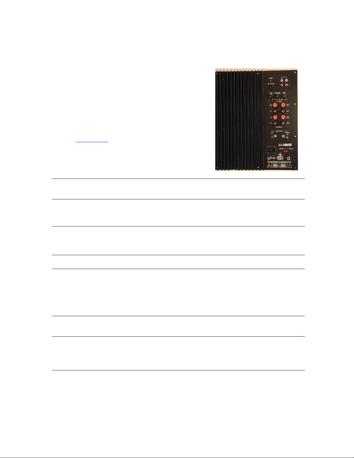
band. In addition, the amplifier is packed with other standard
features such as both speaker level and line level inputs, high-pass
line outputs (12db/oct) for the satellite speakers, continuously
adjustable crossover frequency (40-160hz) for the subwoofer
output, automatic on/off switch (activated by input signal), and a
subwoofer volume control. Mated with a high quality subwoofer
driver, its 350W@4ohm output is enough to shake your room.
Thermal protection and short circuit protection circuitry ensure
long-lasting durability.
Technical specs
Crossover frequency control Continuously variable for the subwoofer from 40hz to 160hz, 2
order characteristic (12db/oct).
Phase control Continuously adjustable phase lag control on the subwoofer from 0
to 180 degrees. This control helps to align the phase shift of the
subwoofer and the satellites for a smooth blending.
Power switch (Auto ON/OFF) When the switch is in the auto position, the amplifier will turn on
when the input signal is present. There are also ON and OFF
positions that can override this function.
Volume control Adjust the output level of subwoofer.
Line in These are line level RCA inputs. When using line level inputs,
connect them from pre-out’s or preamplifier outputs. These inputs
are summed into a mono signal. It is the preferred method of inputs.
For a line level signal that is already mono (for instance, subwoofer
output from home theater receiver), one can connect it to either
channel input. See setup section for more explanation.
Line out Connect them to the inputs, if available, of power amplifier that drive
satellite speakers.
High Level in These are inputs that accept speaker level signals. Use these inputs
when the line level inputs are not used. Connect them directly to the
speaker outputs of the amplifier that drives satellites (or front
channels).
nd

High Level out Speaker level outputs that connect to satellite speakers. Use these
outputs only when speaker level inputs are used. Using speaker level
outputs to drive satellites is not a recommended method because the
impedance of satellite (or front channel) speakers may interact with
the speaker level crossover network on this amp so the frequency
response becomes wavy.
Frequency Control
(Extension Filter)
This controls the frequency of the extension (or rumble) filter. Three
positions are available: 14hz, 20hz, and 28hz. The damping factor (or
inverse of Q value) can be controlled separately (see below).
Damping Control
(Extension Filter)
This controls the damping factor of the extension filter. Three
positions are available: low, medium, and high. Combined with 3
positions in the frequency control, there are a total of 9
combinations.
Extension (or rumble) Filter
Two toggle switches beneath the binding posts constitute the
extension filter controls: one controls the frequency (14,20,and
28) while the other controls the damping factor (inverse of Q
value). These switches control the frequency response contour
in the lower bass band. They serve three purposes: 1) limit the
excursion when excessive rumble signal is present in the
playback (with high damping setting), 2) reduce “room gain” if
it becomes noticeable (with high damping setting), and 3) minor boost at the lower end to further extend the
bass extension (with med and low damping settings).
“Room gain” is the boost of signal energy in the bass band inside a close room due to heavy wall
reflections. Excessive room gain can blur the bass or change the spectral balance of sound. High damping
setting can be used to reduce its impact. It is a Bessel filter with Q=0.6.
On the other hand, small vented box has a tendency of premature roll-off. To compensate that, we provide
med damping (1.5db boost) and low damping (3db boost).
Graph: The frequency response when the frequency setting is at 20hz is shown in Figure 1 for 3 different
Fig 1 3 damping settings at 20hz
Fig 2 Phase response of Fig 11
 Loading...