

Page 1

Spirometer
Owner’s Guide
Page 2

This document was, as far as possible, accurate at the time of release. However,
changes may have been made to the software and hardware it describes since
then. ADInstruments Pty Ltd reserves the right to alter specifications as
required. Late-breaking information may be supplied separately.
Trademarks of ADInstr uments
PowerLab
®
, LabTutor® and MacLab® are registered trademarks of ADInstruments
Pty Ltd. The names of specific recording units, such as PowerLab 8/30, are
trademarks of ADInstruments Pty Ltd. LabChart, Chart and Scope (application
programs) are trademarks of ADInstruments Pty Ltd.
Other Trademarks
Apple, Mac and Macintosh are registered trademarks of Apple Computer, Inc.
Windows, Windows XP and Windows Vista are either registered trademarks or
trademarks of Microsoft Corporation.
All other trademarks are the property of their respective owners.
Product: ML141 Spirometer
Document Number: U-ML141-OG-003C
Part Number: 4381
Copyright © March 2008 ADInstruments Pty Ltd.
Unit 13, 22 Lexington Drive, Bella Vista, NSW 2153, Australia
All rights reserved. No part of this document may be reproduced by any means
without the prior written permission of ADInstruments Pty Ltd.
Web: www.adinstruments.com
Technical Support: support.au@adinstruments.com
Documentation: documentation@adinstruments.com
ADInstruments Pty Ltd. ISO 9001:2000 Certified Quality Management System
Reg. No. 1053
ii
Spirometer Owner’s Guide
Page 3

Contents
Safety Notes 5
1 Overview 13
How to Use This Guide . . . . . . . . . . . . . . . . . . . . . . . . . . . . . . . 14
Checking the Front-end . . . . . . . . . . . . . . . . . . . . . . . . . . . . . 14
Front-end Basics. . . . . . . . . . . . . . . . . . . . . . . . . . . . . . . . . . 14
The Front-end . . . . . . . . . . . . . . . . . . . . . . . . . . . . . . . . . . . . . 15
The Front Panel . . . . . . . . . . . . . . . . . . . . . . . . . . . . . . . . . . 15
The Status Indicator . . . . . . . . . . . . . . . . . . . . . . . . . . . . . . 16
The Spirometer Input Pipes . . . . . . . . . . . . . . . . . . . . . . . . . 16
The Back Panel . . . . . . . . . . . . . . . . . . . . . . . . . . . . . . . . . . 16
2
I
C Input and Output Sockets . . . . . . . . . . . . . . . . . . . . . . . . 16
The Analog Out Socket . . . . . . . . . . . . . . . . . . . . . . . . . . . . 17
Equipment and Technique . . . . . . . . . . . . . . . . . . . . . . . . . . . . . . 17
Using the Spirometer . . . . . . . . . . . . . . . . . . . . . . . . . . . . . . . 17
Fitting the Flow Head. . . . . . . . . . . . . . . . . . . . . . . . . . . . . 18
Calibrating the Flow Head . . . . . . . . . . . . . . . . . . . . . . . . . . 19
Reducing Drift . . . . . . . . . . . . . . . . . . . . . . . . . . . . . . . . . 21
Contents
2 Setting Up 23
Connecting to the PowerLab. . . . . . . . . . . . . . . . . . . . . . . . . . . . . 24
Single Front-ends . . . . . . . . . . . . . . . . . . . . . . . . . . . . . . . 24
Multiple Front-ends . . . . . . . . . . . . . . . . . . . . . . . . . . . . . . 25
Using LabChart and Scope. . . . . . . . . . . . . . . . . . . . . . . . . . . . . . 25
The Front-end Driver . . . . . . . . . . . . . . . . . . . . . . . . . . . . . 26
Front-end Self-test. . . . . . . . . . . . . . . . . . . . . . . . . . . . . . . 26
The Spirometer . . . . . . . . . . . . . . . . . . . . . . . . . . . . . . . . . . . . 27
Signal Display . . . . . . . . . . . . . . . . . . . . . . . . . . . . . . . . . 27
Setting the Range . . . . . . . . . . . . . . . . . . . . . . . . . . . . . . . 28
Filtering. . . . . . . . . . . . . . . . . . . . . . . . . . . . . . . . . . . . . 28
Inverting the Signal . . . . . . . . . . . . . . . . . . . . . . . . . . . . . . 28
Offset Adjustment. . . . . . . . . . . . . . . . . . . . . . . . . . . . . . . 28
Units . . . . . . . . . . . . . . . . . . . . . . . . . . . . . . . . . . . . . . 29
iii
Page 4

A Technical Aspects 31
Spirometer Operation . . . . . . . . . . . . . . . . . . . . . . . . . . . . . . . . . 32
B Troubleshooting 35
Problems and Solutions . . . . . . . . . . . . . . . . . . . . . . . . . . . . . . . . 36
C Specifications 39
Input . . . . . . . . . . . . . . . . . . . . . . . . . . . . . . . . . . . . . . . . . . 39
Filters . . . . . . . . . . . . . . . . . . . . . . . . . . . . . . . . . . . . . . . . . . 40
Control Port . . . . . . . . . . . . . . . . . . . . . . . . . . . . . . . . . . . . . . 40
Physical Configuration . . . . . . . . . . . . . . . . . . . . . . . . . . . . . . . . 40
Index 41
iv
Spirometer
Owner’s Guide
Page 5
Safety Notes
Statement of Intended Use
All products manufactured by ADInstruments are intended for use in
teaching and research applications and environments only.
ADInstruments products are NOT intended to be used as medical
devices or in medical environments. That is, no product supplied by
ADInstruments is intended to be used to diagnose, treat or monitor a
subject. Furthermore no product is intended for the prevention, curing
or alleviation of disease, injury or handicap.
Safety Notes
Where a product meets IEC 60601-1 it is under the principle that:
• it is a more rigorous standard than other standards that could be
chosen, and
• it provides a high safety level for subjects and operators.
The choice to meet IEC 60601-1 is in no way to be interpreted to mean
that a product:
• is a medical device,
• may be interpreted as a medical device, or
• is safe to be used as a medical device.
5
Page 6
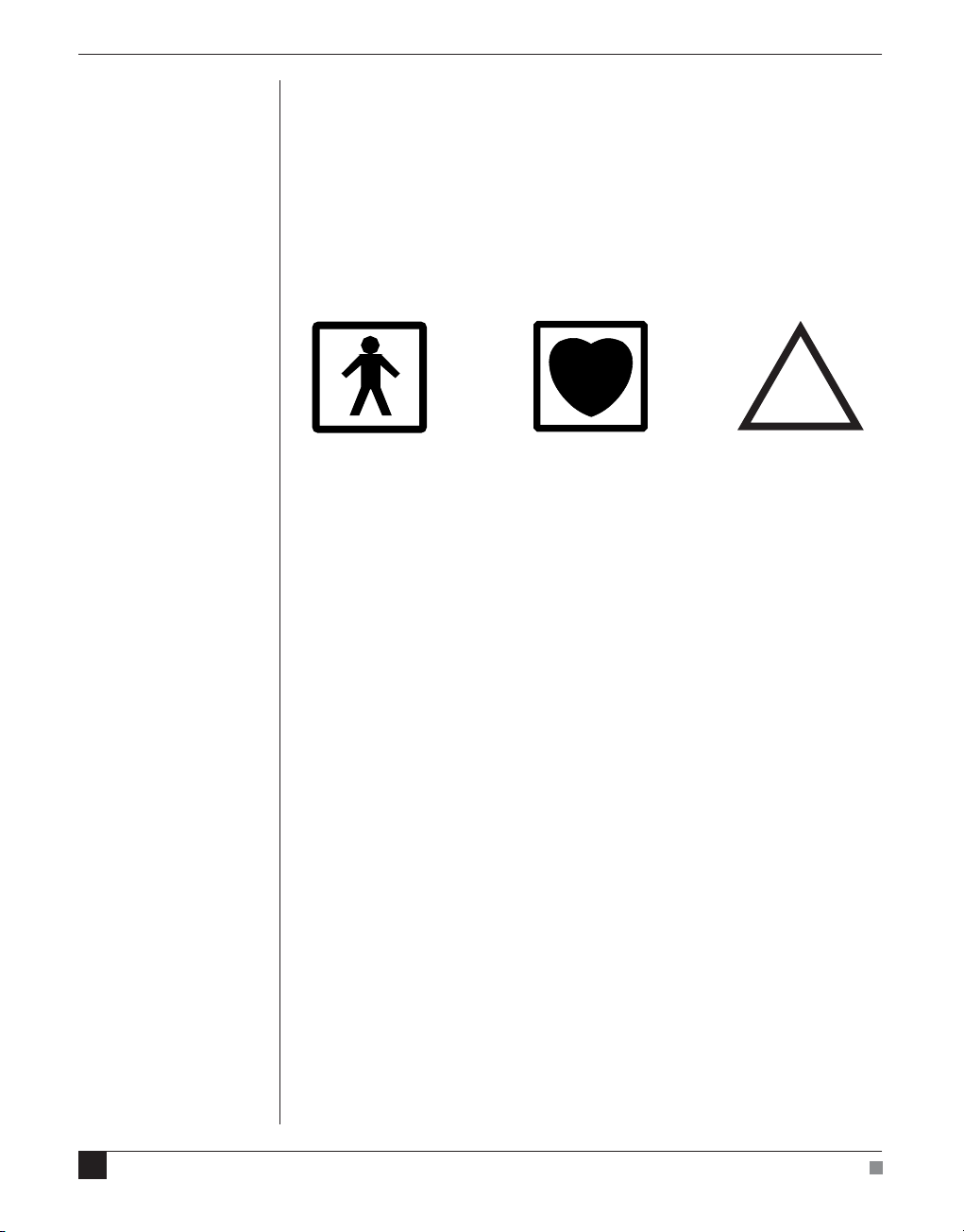
Safety Symbols
Devices manufactured by ADInstruments that are designed for direct
connection to humans are tested to IEC 601-1:1998 (including
amendments 1 and 2) and 60601-1-2, and carry one or more of the
safety symbols below. These symbols appear next to those inputs and
output connectors that can be directly connected to human subjects.
!
BF symbol: Bodyprotected equipment
The three symbols are:
• BF (body protected) symbol. This means that the input connectors
are suitable for connection to humans provided there is no direct
electrical connection to the heart.
• CF (cardiac protected) symbol. This means that the input
connectors are suitable for connection to human subjects even
when there is direct electrical connection to the heart.
• Warning symbol. The exclamation mark inside a triangle means
that the supplied documentation must be consulted for operating,
cautionary or safety information before using the device.
Further information is available on request.
CF symbol: Cardiacprotected equipment
Warning symbol: ‘see
documentation’
Bio Amp Safety Instructions
The Bio Amp inputs displaying any of the safety symbols are
electrically isolated from the mains supply in order to prevent current
flow that may otherwise result in injury to the subject. Several points
must be observed for safe operation of the Bio Amp:
6
Spirometer Owner’s Guide
Page 7

• All Bio Amp front-ends (except for the ML138 Octal Bio Amp) and
PowerLab units with a built-in Bio Amp are supplied with a 3-lead
or 5-lead Bio Amp subject cable and lead wire system. The ML138
Octal Bio Amp is supplied with unshielded lead wires (1.8 m). Bio
Amps are only safe for human connection if used with the
supplied subject cable and lead wires.
• All Bio Amp front-ends and PowerLab units with a built-in Bio
Amp are not defibrillator-protected. Using the Bio Amp to record
signals during defibrillator discharges may damage the input
stages of the amplifiers. This may result in a safety hazard.
• Never use damaged Bio Amp cables or leads. Damaged cables and
leads must always be replaced before any connection to humans is
made.
Isolated Stimulator Safety
Instructions
The Isolated Stimulator outputs of a front-end signal conditioner or
PowerLab with a built-in isolated stimulator are electrically isolated.
However, they can produce pulses of up to 100 V at up to 20 mA.
Injury can still occur from careless use of these devices. Several points
must be observed for safe operation of the Isolated Stimulator:
Safety Notes
• The Isolated Stimulator output must only be used with the
supplied bar stimulus electrode.
• The Isolated Stimulator output must not be used with individual
(physically separate) stimulating electrodes.
• Stimulation must not be applied across the chest or head.
• Do not hold one electrode in each hand.
• Always use a suitable electrode cream or gel and proper skin
preparation to ensure a low-impedance electrode contact. Using
electrodes without electrode cream can result in burns to the skin
or discomfort for the subject.
• Subjects with implantable or external cardiac pacemakers, a
cardiac condition, or a history of epileptic episodes must not be
subject to electrical stimulation.
• Always commence stimulation at the lowest current setting and
slowly increase the current.
• Stop stimulation if the subject experiences pain or discomfort.
7
Page 8

• Do not use faulty cables, or those that have exhibited intermittent
faults.
• Do not attempt to measure or record the Isolated Stimulator
waveform while connected to a subject using a PowerLab input or
any other piece of equipment that does not carry the appropriate
safety symbol (see Safety Symbols above).
Always check the status indicator on the front panel. It will always
flash green each time the stimulator delivers a current pulse. A yellow
flash indicates an ‘out-of-compliance’ (OOC) condition that may be
due to the electrode contact drying up. Always ensure that there is
good electrode contact at all times. Electrodes that are left on a subject
for some time need to be checked for dry contacts. An electrode
impedance meter can be used for this task.
• Always be alert for any adverse physiological effects in the subject.
At the first sign of a problem, stimulation must be stopped, either
from the software or by flicking down the safety switch on the
front panel of any built-in Isolated Stimulator or the ML180
Stimulus Isolator.
• The ML180 Stimulus Isolator is supplied with a special
transformer plug pack. The plug pack complies with medical
safety requirements. Therefore, under no circumstances should
any other transformer be used with the Stimulus Isolator. For a
replacement transformer plug pack please contact your nearest
ADInstruments representative.
General Safety Instructions
To achieve the optimal degree of subject and operator safety,
consideration should be given to the following guidelines when
setting up a PowerLab system either as stand-alone equipment or
when using PowerLab equipment in conjunction with other
equipment. Failure to do so may compromise the inherent safety
measures designed into PowerLab equipment. The following
guidelines are based on principles outlined in the international safety
standard IEC60601-1-1: General requirements for safety - Collateral
standard: Safety requirements for medical systems . Reference to this
standard is required when setting up a system for human connection.
8
Spirometer Owner’s Guide
Page 9

PowerLab systems (and many other devices) require the connection of
a personal computer for operation. This personal computer should be
certified as complying with IEC60950 and should be located outside a
1.8 m radius from the subject (so that the subject cannot touch it while
connected to the system). Within this 1.8 m radius, only equipment
complying with IEC60601-1 should be present. Connecting a system
in this way obviates the provision of additional safety measures and
the measurement of leakage currents.
Accompanying documents for each piece of equipment in the system
should be thoroughly examined prior to connection of the system.
While it is not possible to cover all arrangements of equipment in a
system, some general guidelines for safe use of the equipment are
presented below:
• Any electrical equipment which is located within the SUBJECT
AREA should be approved to IEC60601-1.
• Only connect those parts of equipment that are marked as an
APPLIED PART to the subject. APPLIED PARTS may be
recognized by the BF or CF symbols which appear in the Safety
Symbols section of these Safety Notes.
• Only CF-rated APPLIED PARTS must be used for direct cardiac
connection.
• Never connect parts which are marked as an APPLIED PART to
those which are not marked as APPLIED PARTS.
• Do not touch the subject to which the PowerLab (or its peripherals)
is connected at the same time as making contact with parts of the
PowerLab (or its peripherals) that are not intended for contact to
the subject.
• Cleaning and sterilization of equipment should be performed in
accordance with manufacturer’s instructions. The isolation barrier
may be compromised if manufacturer’s cleaning instructions are
not followed.
• The ambient environment (such as the temperature and relative
humidity) of the system should be kept within the manufacturer’s
specified range or the isolation barrier may be compromised.
• The entry of liquids into equipment may also compromise the
isolation barrier. If spillage occurs, the manufacturer of the affected
equipment should be contacted before using the equipment.
Safety Notes
9
Page 10

• Many electrical systems (particularly those in metal enclosures)
depend upon the presence of a protective earth for electrical safety.
This is generally provided from the power outlet through a power
cord, but may also be supplied as a dedicated safety earth
conductor. Power cords should never be modified so as to remove
the earth connection. The integrity of the protective earth
connection between each piece of equipment and the protective
earth should be verified regularly by qualified personnel.
• Avoid using multiple portable socket-outlets (such as power
boards) where possible as they provide an inherently less safe
environment with respect to electrical hazards. Individual
connection of each piece of equipment to fixed mains socketoutlets is the preferred means of connection.
If multiple portable socket outlets are used, they are subject to the
following constraints:
• They shall not be placed on the floor.
• Additional multiple portable socket outlets or extension cords
shall not be connected to the system.
• They shall only be used for supplying power to equipment which
is intended to form part of the system.
10
Cleaning and Sterilization
ADInstruments products may be wiped down with a lint free cloth
moistened with industrial methylated spirit. Refer to the
manufacturer’s guidelines or the Data Card supplied with transducers
and accessories for specific cleaning and sterilizing instructions.
Preventative Inspection and
Maintenance
PowerLab systems and ADInstruments front-ends are all
maintenance-free and do not require periodic calibration or
adjustment to ensure safe operation. Internal diagnostic software
performs system checks during power up and will report errors if a
significant problem is found. There is no need to open the instrument
for inspection or maintenance, and doing so within the warranty
period will void the warranty.
Spirometer Owner’s Guide
Page 11

Your PowerLab system can be periodically checked for basic safety by
using an appropriate safety testing device. Tests such as earth leakage,
earth bond, insulation resistance, subject leakage and auxiliary
currents and power cable integrity can all be performed on the
PowerLab system without having to remove the covers. Follow the
instructions for the testing device if performing such tests.
If the PowerLab system is found not to comply with such testing you
should contact your PowerLab representative to arrange for the
equipment to be checked and serviced. Do not attempt to service the
device yourself.
Environment
Electronic components are susceptible to corrosive substances and
atmospheres, and must be kept away from laboratory chemicals.
Storage Conditions
• Temperature in the range 0–40 °C
• Non-condensing humidity in the range 0–95%.
Operating Conditions
• Temperature in the range 5–35 °C
• Non-condensing humidity in the range 0–90%.
Disposal
• Forward to recycling center or return to manufacturer.
Safety Notes
11
Page 12

12
Spirometer Owner’s Guide
Page 13

1
Overview
The Spirometer is a modular device, in a family called front-ends,
designed to extend the capabilities of the PowerLab
Spirometer is a precision differential pressure transducer for
measurements of respiration flows.
®
system. The
Chapter 1 Overview
This chapter provides an overview of the Spirometer Front-end,
describing its features, and discusses aspects of its use.
13
Page 14

How to Use This Guide
This owner’s guide describes how to set up and begin using your
Spirometer. The chapters give an overview of front-ends in general
and the Spirometer in particular, and discuss how to connect the
hardware, perform a simple power-up test, and use the front-end with
some ADInstruments programs. The appendices provide technical
information about the Spirometer, and take a look at some potential
problems and their solutions.
At the end of this guide, you’ll find an index. Technical terms that are
not defined in the glossary of terms included with the owner’s guide
for your PowerLab, or in the guide that came with your computer, are
defined as they appear.
Checking the Front-end
Before connecting the Spirometer to anything, check it carefully for
signs of physical damage.
1. Check there are no signs of damage to the outside of the front-end.
2. Check that there is no obvious sign of internal damage, such as
rattling. Pick up the front-end, tilt it gently from side to side, and
listen for anything that appears to be loose.
If you have found a problem, contact your authorized ADInstruments
representative immediately, and describe the problem. Arrangements
can be made to replace or repair the front-end.
Front-end Basics
The PowerLab system consists of a recording unit and application
programs that run on the computer to which the unit is connected. It
is an integrated system of hardware and software designed to record,
display, and analyze experimental data. Your Spirometer is one of a
family of front-ends meant for use with your PowerLab system.
Front-ends are ancillary devices connected to the PowerLab recording
unit to extend the system’s capabilities. They provide additional
signal conditioning and other features, and extend the types of
experiments that you can conduct and the data you can record. All
ADInstruments front-ends are designed to be operated under full
software control. No knobs, dials or switches are needed, although
some may be provided for reasons of convenience or safety.
14
Spirometer
Owner’s Guide
Page 15

The PowerLab controls front-ends through an expansion connector
called the I
2
C (eye-squared-sea) bus. Each additional front-end
connects to the previous front-end, in a simple daisy-chain structure,
making it very easy to add front-ends to the system or to transfer
them between PowerLabs. In general, each front-end requires a
positive analog input channel of the PowerLab, although the Stimulus
Isolator and similar front-ends require the positive analog output.
Front-ends are automatically recognized by the PowerLab system.
Any front-end feature such as gain or filtering is combined with the
appropriate features of the program and presented as a single set of
software controls. This seamless integration of front-ends greatly
increases the flexibility and ease of use of the PowerLab system.
The Front-end
The Spirometer is a precision differential pressure transducer for
measuring respiratory variables, such as inspiration and expiration
flows and tidal volumes. It measures differential pressure across fine
gauze mounted in a flow head. With a flow head of a suitable size, the
Spirometer can be used with a variety of creatures, from small animals
such as mice and rats, to large animals and humans. Accessories such
as flow heads (various sizes), tubing, and calibration syringes are
available, and can be purchased separately.
Figure 1–1
The front panel of the
Spirometer
Chapter 1 Overview
The rest of this chapter contains general information about the
features, connections, and indicators of the Spirometer. It also looks at
the flow head and its calibration for spirometry. More detailed
information can be found in the technical appendices.
The Front Panel
Input pipes
Status indicator
15
Page 16

The Status Indicator
When an ADInstruments program, such as LabChart, starts up the
Status indicator light should flash briefly and then remain green,
indicating that the program has found the front-end, checked and
selected it, and is ready to use it. If it does not turn on and stay on
when the program is run, this indicates either that the front-end is not
connected properly or that there is a software or hardware problem.
The Spirometer Input Pipes
WARNING
The Spirometer input is
sensitive. Do not blow into
or apply high air flows to
the Spirometer input, as
this may damage the
internal transducer
Figure 1–2
The back panel of the
Spirometer
Connections are made to the Spirometer using two pipes on the front
panel. These are physical connections for airflow, not electrical ones.
Two flexible plastic tubes (3 mm internal diameter, 5 mm external
diameter) connect the input pipes on the Spirometer to the connection
pipes on the flow head. The input pipes carry a warning symbol (see
margin).
The Back Panel
2
I
C Input and Output Sockets
Two nine-pin sockets are used to communicate with the PowerLab
(they are marked ‘I
circuitry such as cables and connectors). These sockets, in conjunction
with the proper cables, allow multiple front-ends to be used
independently with one PowerLab. Power and control signals to
connected front-ends come from the PowerLab. ADInstruments
front-ends are connected to each other in series, output to input
(discussed in more detail in the next chapter).
2
C Bus’: a ‘bus’ is simply information-transmission
Signal output to PowerLab
16
2
C connection to PowerLab
I
2
C connection to other
I
front-ends
Spirometer
Owner’s Guide
Page 17

The Analog Out Socket
The Signal Output provides the signal to an analog input socket on
the front of the PowerLab. A BNC-to-BNC cable is supplied for this
connection. If you are using a PowerLab with differential inputs, only
connect the cable to a positive input. ADInstruments applications will
not find the front-end on start up if a negative input is used.
Equipment and Technique
Using the Spirometer
The ADInstruments Spirometer and an attached flow head together
function as a pneumotachometer, with an output signal proportional
to the airflow during breathing. Airflow is measured by means of a
pressure differential across a fine wire mesh inside the flow head. This
works on the principle that air flowing through an orifice of fixed
cross-section produces a pressure difference across the mesh
proportional to the air’s velocity — within certain limits. The greater
the velocity of the air (that is, the higher the flow), the larger the
pressure difference.
Chapter 1 Overview
The flow head itself contains no electronic parts, and is simply a tube
with a wire mesh placed across it. Two pipes, one on either side of the
mesh, allow the pressure difference to be measured by a highprecision differential pressure transducer in the Spirometer itself,
when connected with plastic tubing.
The Spirometer can support several sizes of flow head, each with
differing maximum flows, but all with the same connection to the
Spirometer. Standard flow heads, obtainable separately, are:
• MLT1L Respiratory Flow Head, 1 L/min, suitable for mice
• MLT10L Respiratory Flow Head, 10 L/min, suitable for rats
• MLT300L Respiratory Flow Head, 300 L/min, suitable for adult
humans at rest
• MLT3813H Heated Pneumotach, 800 L/min, suitable for adult
humans during exercise
• MLT1000L Respiratory Flow Head, 1000 L/min, suitable for adult
humans during exercise.
17
Page 18

Figure 1–3
A flow head, with the pipes
in the correct position:
upright
Fitting the Flow Head
To connect the flow head to the Spirometer, simply push the ends of
the two connection tubes firmly over the flow head pipes and over the
input pipes on the front panel of the Spirometer. In some cases you
may find that the tubes are difficult to fit because they are too tight. If
so, dip the ends of the tubes into some boiling water to soften the
plastic to make it easier to push the tubes onto the pipes.
Any leakage from the joint will affect the precision of the flow
readings, so ensure that the tubes are pushed on firmly. The flow head
is washable and able to be cold-sterilized, and should be dried gently
before use. Care should be taken to ensure that condensation does not
block the tubing connecting the flow head to the Spirometer. To avoid
problems, the flow head should be turned so that the tubing connects
at the top, not at the bottom.
18
More elaborate setups are possible. In human respiration, disposable
mouthpieces and filters would be usual, to prevent contamination,
and minimize drift due to moisture (the filter helps remove droplets).
For humans during exercise, the flow head could be fixed in position,
perhaps attached to a stand, and connected to a mouthpiece and filter
by a length of wide-bore flexible tubing, to allow the subject to
exercise freely. To obtain useful results with any method of spirometry,
all the air breathed by the subject must be measured. A nose clip
prevents inadvertent nasal breathing. With a little practice, the subject
can prevent air leaks around the mouthpiece.
ADInstruments supplies suitable accessories separately:
• MLA140 Spirometer kit (containing each item below)
• MLA1026 Pack of 10 vinyl disposable mouthpieces
• MLA1008 Pack of 50 foam-tipped disposable nose clips
• MLA304 Pack of 50 disposable droplet filters
• MLA1011A Clean bore tubing, 250 mm long by 35 mm i.d.
Spirometer Owner’s Guide
Page 19

Calibrating the Flow Head
Before using the flow head, you will probably want to calibrate the
Spirometer to read in terms of flow (L/s rather than V). There are two
ways of doing this: using an approximate conversion factor, or
injecting a known volume and integrating. The Spirometry Extension
for LabChart (available on both Windows and Macintosh platforms)
can be used to assist with either of these methods.
Using an approximate conversion factor . You can use an approximate
conversion value for converting the voltage signal to L/s. For the
MLT1000L Flow Head, the linear conversion is given approximately
by 0 V = 0 L/s; 1 V = 40.1 L/s. You apply this conversion in the Units
Conversion dialog, opened from the Channel Function pop-up menu.
Injecting a known volume and integrating . You can determine an
accurate conversion value for your particular flow head by injecting a
known volume of air through the breathing circuit and integrating the
flow signal in LabChart. This section describes the procedure in detail.
ADInstruments has calibration syringes available for this purpose,
such as the a 3-liter MLA5530 calibration syringe. Try to depress the
plunger at a steady rate, neither too quickly or too slowly, and try not
to bring the plunger to an abrupt stop at the end of the syringe.
Connect the Spirometer to an input on the PowerLab. Set up that
input channel using the Channel Settings dialog: change the channel
name to ‘Flow’ and click
Spirometer…
in the Input Settings column to
display the Spirometer dialog. You can then set the range to a suitable
value, such as 500 mV or 200 mV, and click
to zero the flow head
Zero
signal. You should always do this before you start recording.
Set up a new channel for Volume from the Channel Settings dialog.
Display the integral of the flow signal in this channel by choosing
Integral…
from the Channel Function pop-up menu and selecting
Flow
as the source channel, using a standard integral with no reset.
Injections can now be recorded and integrated using the spirometer
(flow) and volume channels. Making a single injection should produce
a trace similar to that shown in Figure 1–4 – a 3 L calibration syringe
was used to simulate a single expiration. The absolute value of the
integral at the cursor position is 76.79 mV.s. This corresponds to a flow
head correction factor of 39.1 L/s/V, obtained by dividing the syringe
volume by the integral value (converted to V.s).
Chapter 1 Overview
19
Page 20

Figure 1–4
The flow signal integrated
for a single injection.
The value of the integral at
the cursor position is
–76.79 mV.s
Figure 1–5
Setting units to calibrate
the Spirometer channel
3 L
----------------------------- 39.1 L/s/V=
0.07679 V.s
The correction factor is applied in the Units Conversion dialog
(0 V = 0 L/s; 1 V = 39.1 L/s).
20
Using the Spirometry Extension. The Spirometry Extension for
LabChart (for either the Windows or Macintosh platforms) is available
from the ADInstruments website and can be used to perform the units
conversion required for the Spirometer channel, using either an
approximate conversion value or a value calculated by integrating the
injection of a known volume. The extension adds an item called
Spirometry Flow... to the Channel Function pop-up menu.
Full details on using the Spirometry Extension can be found in the
Spirometry Extension User’s Guide (Macintosh) which is installed with
the software, or in the Help Center (Windows).
Spirometer Owner’s Guide
Page 21

Reducing Drift
The Spirometer is subject to drift for various reasons. There are a
number of ways to reduce this. Zeroing the Spirometer immediately
before use is an essential step in the setup procedure. Zeroing ensures
that the recorded flow signal is zero when there is no airflow, and
thereby prevents steady drift of the integrated volume trace.
Internal drift in the Spirometer’s electronics is minimized if you leave
the PowerLab unit and Spirometer turned on for 15 minutes or so,
before zeroing and use. We recommend placing the Spirometer beside
the PowerLab unit, or on a shelf above, to avoid its being affected by
heat from the power supply.
Expired volume is greater than inspired volume in most atmospheric
conditions. The increase, due to warming and humidification, is
typically 5–10%. For this reason there may be ‘breath-dependent drift’
of an integrated (volume) trace even when the Spirometer is correctly
zeroed. Non-ideal distribution of air flow across the flow head’s mesh
screen may also contribute to breath-dependent drift. This component
of drift is minimized by use of disposable droplet filters.
Finally, if you are using the Spirometry Extension, you can apply drift
correction after recording, provided that your recording meets certain
conditions. For more details on drift correction, please refer to the
Spirometry Extension User’s Guide (Macintosh) or the Help Center
(Windows).
Chapter 1 Overview
21
Page 22

22
Spirometer Owner’s Guide
Page 23

2 Setting Up
This chapter describes connecting the Spirometer to your PowerLab
and performing a quick test to make sure that it is working properly.
The best way to configure your system for one or more front-ends is
discussed, along with how to use the front-end with ADInstruments
software.
Chapter 2 Setting Up
23
Page 24

Connecting to the PowerLab
To connect a front-end to the PowerLab, first ensure that the
PowerLab is turned off. Failure to do this may damage the PowerLab,
the front-end, or both.
Connect the Signal Output on the rear panel of the Spirometer to an
analog input on the front panel of the PowerLab using a BNC cable.
If the PowerLab has differential inputs (+ and – channels), rather than
single-ended inputs, then you must connect the BNC cable to one of
the positive analog input channels. PowerLab applications will not
find the front-end on starting up if a negative input is used.
Single Front-ends
Connect the I2C output of the PowerLab to the I2C input of the frontend using the I2C cable provided.
Figure 2–1
Connecting a front-end to
the PowerLab: a PowerLab
has only one I
and each front-end has one
2
I
C output and one I2C input
2
C output,
Front-end I2C Input Front-end Signal Output
PowerLab I2C Output
2
Check that the plugs for the I
C bus are screwed in firmly. Check the
BNC cable for firm connections as well. Loose connectors can cause
erratic front-end behavior, or may cause the front-end to fail to work
at all. The BNC cable can be tucked under the front-end to keep it out
of the way if desired.
24
Spirometer Owner’s Guide
Page 25

Multiple Front-ends
Multiple front-ends can be connected up to a PowerLab; up to sixteen,
depending on the number of positive inputs sockets on the PowerLab.
The first front-end is connected with the I2C cable as in Figure 2–1.
The remainder are daisy-chained via I2C cables, connecting the I2C
Output of the previous connected front-end to the I2C Input of the
next front-end to be added. The BNC cable for each front-end is
connected to one of the positive analog inputs of the PowerLab.
Figure 2–2
Connecting multiple
front-ends to the PowerLab
(two single front-ends
shown for simplicity)
Front-end I2C inputs
PowerLab I2C output
Front-end I2C output
Using LabChart and Scope
Front-ends are used with PowerLabs and ADInstruments programs
such as LabChart and Scope. The combined amplification and filtering
of the Spirometer, the PowerLab and the program and presented as a
single set of software controls.
Chapter 2 Setting Up
When the Spirometer is connected to a channel and successfully
installed, the Input Amplifier… menu command from the Channel
Function pop-up menu in LabChart is replaced by the Spirometer…
menu command. In Scope, the Input Amplifier… button in the Input A
(or Input B) panel is replaced by the Spirometer… button. The
LabChart Help Center and Scope User’s Guide have details on the Input
Amplifier dialog, and explain some of the software terms used here.
25
Page 26

If the application fails to find a front-end attached, the normal text
remains. If you were expecting a connected front-end, close the
program, turn the PowerLab off and check the connections. Then
restart the PowerLab and program. Note: do not leave the PowerLab
on while checking the connections, as doing so may damage the
PowerLab, the front-end, or both.
Choosing the Spirometer… menu command or clicking the button will
open the Spirometer dialog. Only the Spirometer dialog for LabChart
is described here, but the Spirometer dialog for Scope is similar.
The Front-end Driver
There are several front-end drivers for the various front-ends made by
ADInstruments (a driver is a piece of software the computer uses to
control a peripheral device). For example the Bridge Amplifier frontend driver is used with the Spirometer and GP Amp; and the Stimulus
Isolator front-end driver is used with the Stimulus Isolator.
In order for the Spirometer to be recognized by PowerLab software,
the Bridge Amplifier front-end driver must be present. It should have
been installed when the LabChart and Scope applications were
installed on your computer. If it is not present, then you may need to
reinstall the software or obtain a software update.
26
Front-end Self-test
Once the Spirometer is properly connected to the PowerLab, and the
proper software is installed on the computer, a quick check can be
performed on the front-end. To perform the self-test:
1. Turn on the PowerLab and check that it is working properly, as
described in the owner’s guide that was supplied with it.
2. Once the PowerLab is ready, open either LabChart or Scope. While
the program is opening, keep a close eye on the Status indicator
for the Spirometer (at the bottom right of the front panel).
During initialization, you should see the indicator flash briefly
and then remain lit.
If the indicator lights correctly, the front-end has been found by the
PowerLab and is working properly, and you can close the application
or carry on as appropriate. If the indicator doesn’t light, check your
cable connections and repeat the procedure. If this does not solve the
problem, contact your ADInstruments representative.
Spirometer Owner’s Guide
Page 27

The Spirometer
The Spirometer dialog allows software control of the combined filters
and other circuitry in the PowerLab and Spirometer. Change settings
in the dialog, then click OK to apply them. To set up many channels
quickly, click the arrows by the dialog title, or press the right or left
arrow keys on the keyboard, to move to the equivalent dialogs for
adjacent channels. This skips channels that are turned off. The channel
number is shown next to the arrows, and the channel title or axis label
(if any) is shown along the vertical Amplitude axis.
Figure 2–3
The Spirometer dialog
(LabChart for Windows;
the Macintosh and Scope
versions are similar)
Signal amplitude Pause/Scroll buttons
Range
options
Filter
options
Amplitude
axis
Click this
to remove
the offset
for the
Spirometer
Signal Display
The signal at the channel input is displayed so you can see the effect
of changing the settings – data is not recorded while setting things up.
Slowly changing signals are represented quite accurately, whereas
quickly changing signals are displayed as a solid dark area showing
only the envelope (shape) of the signal from minimum and maximum
recorded values. The average signal value is displayed at the top of
the display area: the offset is displayed when the Spirometer is not
zeroed, and may indicate a problem if it is large.
Chapter 2 Setting Up
You can stop the signal scrolling by clicking the Pause button at the
bottom left (Macintosh) or top right (Windows) of the data display
area. This changes to the Scroll button on the Macintosh. Click the
Scroll button to start scrolling again.
27
Page 28

Shift and stretch the vertical Amplitude axis, by clicking and dragging
it in various ways, to make the best use of the available display area.
It functions the same as the Amplitude axis of the Chart Window,
controls are identical and any change is applied to the Chart Window.
Setting the Range
The Range pop-up menu lets you select the input range or sensitivity
of the channel. Changing the range in the Spirometer dialog is
equivalent to changing it in the Chart or Scope window. The available
ranges are 500 mV, 200 mV, 100 mV, 50 mV and 20 mV.
Filtering
The Low Pass pop-up menu gives a choice of 1, 10 and 100 Hz
low-pass filters. These filters are appropriate for the built-in pressure
transducer in the Spirometer and help to eliminate high-frequency
components, such as noise, from the input signal.
Inverting the Signal
Click the Invert checkbox to invert the signal displayed on screen. It
provides a simple way to change the polarity of the recorded signal
without having to swap the tubes on the Spirometer or flow head.
For example, you might be recording an experiment where expiration
gives a positive signal, but you want the expired air to give a negative
signal on the screen. The Invert checkbox would change the display.
28
Offset Adjustment
The Spirometer is effectively a pressure transducer and amplifier,
transducing flow into voltage. Transducers almost always produce
some amount of signal, usually small, when at equilibrium or rest.
The signal value above the display area shows this offset – if it is large,
it may indicate a problem. Offsets from a zero reading need to be
removed, in a process called zeroing. Commonly, you may also wants
to remove a constant term from the measurement of interest. This
enables more accurate measurement of the changes in the signal
under stimulus.
Zeroing. To perform automatic zeroing, click Zero: the program works
out a corrective DC voltage that cancels, as closely as possible, the
transducer output voltage. Auto-zeroing takes a few seconds to work
out the best zeroing value at all ranges.
Spirometer Owner’s Guide
Page 29

Note: variations in the transducer signal during the auto-zeroing
operation will cause the software to fail to zero the offset properly, if it
zeroes at all; make sure the Spirometer and flow head are kept still
and that there is no airflow during the auto-zeroing.
Units
Click Units… to open the Units Conversion dialog, with which you can
set the units for a channel and, using waveform measurements,
calibrate the channel. The waveform in the data display area of the
Spirometer dialog is transferred to the data display area of the Units
Conversion dialog. (Use the Pause button to capture a specific signal.)
This units conversion only applies to subsequently recorded signals,
so it is more limited than choosing Units Conversion… from the
Channel Function pop-up menu, as it does not allow the conversion of
individual blocks or pages of data.
Chapter 2 Setting Up
29
Page 30

30
Spirometer Owner’s Guide
Page 31

APPENDIX
A Technical
Aspects
A
This appendix describes some of the important technical aspects of the
Spirometer to give some insight into how it works. You do not need to
know the material here to use a front-end. It is likely to be of especial
interest to the technically minded, indicating what a front-end can and
cannot do, and its suitability for particular purposes. (You should not
use it as a service manual: user modification of the equipment voids
your rights under warranty.)
The Spirometer and other ADInstruments front-ends have been
designed to integrate fully into the PowerLab system. Each requires
connection to the PowerLab via a special communications connector
called the I2C (eye-squared-sea) bus, and a BNC connector.
Appendix A Technical Aspects
31
Page 32

Spirometer Operation
Gain
The Spirometer is essentially an extension of the PowerLab’s analog
input. The Spirometer provides:
• a precision differential pressure input used to determine flow rates
using an attached flow head
• the additional amplification necessary to deal with a variety of
flow rates, from fractions of a liter per minute (mice and rats) to a
thousand liters per minute (adult humans during exercise)
• additional programmable filtering to remove unwanted signal
frequencies
• digitally controlled zeroing circuitry, for offset removal of
unwanted constant flow rates, for instance, to measure volume
accurately when using computed integration.
The internal functions of the Spirometer are controlled from the
PowerLab through the I2C bus, which also supplies power to the
Spirometer. The front-end is also connected to an analog input channel
of the PowerLab via a BNC-to-BNC cable, through which the pressure
signal from the flow head is sent. The overall operation of the
Spirometer can be better understood by referring to Figure A–1.
Block diagram of the
32
Figure A–1
Spirometer
Signal
Signal
Output
Output
I2C
I2C
Output
Output
I2C
I2C
Input
Input
Low-pass Filters
Low-pass Filters
I2C Control
I2C
Interface
Control
+
Interface
Power
+
Supply
Power
Supply
100 Hz
100 Hz
10 Hz
10 Hz
1 Hz
1 Hz
Pressure
Transducer
Transducer
Status
Online
Indicator
Indicator
Pressure
Inputs
Inputs
Gain
Voltage
Voltage
Reference
Reference
Spirometer Owner’s Guide
Pressure
Pressure
Page 33

The Spirometer and an attached flow head together function as a
pneumotachometer, with an output signal proportional to the airflow
rate during breathing. Expired or inspired air has to pass through a
very fine wire mesh in the attached flow head. This creates a pressure
differential between the two sides of the mesh proportional to the flow
rate or velocity of the air passing through the flow head. The input of
the Spirometer is a differential pressure transducer that converts the
differential pressure in the flow head into an analogous voltage. This
output voltage is in turn fed into a programmable gain amplifier,
which provides additional signal amplification. The output of the
amplifier is passed through a set of software-selectable, fourth-order,
low-pass filters. The signal is then sent to the PowerLab.
To remove any offsets caused by its pressure transducer or a signal
baseline, the Spirometer uses a DC offset circuit consisting of a 12-bit
DAC (digital-to-analog converter) that is internally connected to the
input stage when in the DC coupling mode.
Zeroing of offsets is achieved by applying a corrective DC voltage to
the input stage via the DAC, under software control. Since the DAC is
only capable of producing corrective voltages in ‘steps’, a facility to set
the offset range is provided to decrease the size of these steps and
make the zeroing circuit more sensitive, especially at the higher range
settings.
Appendix A Technical Aspects
33
Page 34

34
Spirometer Owner’s Guide
Page 35

B
APPENDIX
B Troubleshooting
This appendix describes most of the common problems that can occur
when using the Spirometer with your PowerLab recording unit. It
covers how these problems are caused, and what you can do to
alleviate them. If the solutions here do not work, earlier chapters, the
LabChart Help Center, and the guide to your PowerLab may contain
possible solutions. If none of the solutions here or elsewhere are of
help, then consult your ADInstruments representative.
Most of the problems that users encounter are connection problems,
and can usually be fixed by checking connections and starting up the
hardware and software again. Very rarely will there be an actual
Appendix B Troubleshooting
problem with the front-end or the PowerLab itself.
35
Page 36

Problems and Solutions
The status indicators fail to light when the software is started, or the
front-end commands and so on do not appear where they should
The I2C cable or the BNC-to-BNC cable from the front-end to the
PowerLab is not connected, has been connected incorrectly (to the
wrong input or output, for instance), or is loose.
• Turn everything off. Check to see that all cables are firmly seated
and screwed in. The BNC cable from the Signal Output of the
Spirometer must be connected to a positive input on the
PowerLab. Make sure the input is the same channel from which
you expect to use the front-end in the software. Start up again to
see if this has fixed the problem.
You are using an early version of LabChart or Scope.
• Upgrade to the latest version of the software. Contact your
ADInstruments representative for information.
The BNC or I2C cable is faulty.
36
• Replace the cable and try again. Immediately label all cables
proved faulty so that you don’t use them again by accident.
The front-end is faulty.
• This is the least likely event. If the front-end will not work
properly after the previous measures, then try using it on another
PowerLab. If the same problems recur with a second PowerLab,
the front-end may be faulty. Contact your ADInstruments
representative to arrange for repairs.
On starting up the software, an alert indicates that there is a problem
with the front-end or driver
The correct Bridge driver is not installed on your computer.
• Reinstall the software.
Spirometer Owner’s Guide
Page 37

You are using an early version of LabChart or Scope.
• Upgrade to the latest version of the software. Contact your
ADInstruments representative for information.
The BNC or I2C cable is faulty.
• Replace the cable and try again. Immediately label all cables
proved faulty so that you don’t use them again by accident.
The front-end is faulty.
• This is the least likely event. If the front-end will not work
properly after the previous measures, then try using it on another
PowerLab. If the same problems recur with a second PowerLab,
the front-end may be faulty. Contact your ADInstruments
representative to arrange for repairs.
Some software settings don’t resemble those in this guide
You are using an early version of the front-end driver, or of LabChart
or Scope. Some changes may have been made since then.
• Upgrade to the latest version of the software. Contact your
ADInstruments representative for information.
The trace will not zero properly when using the automatic or manual
zeroing controls
Variations in the signal during auto-zeroing may cause the software to
fail to zero the offset properly, if it zeroes at all.
• Make sure that the apparatus is kept still and that no varying
signal is applied during auto-zeroing.
The signal from the flow head is beyond the range of the Spirometer’s
zeroing circuitry.
• You may need to use another, more suitable, flow head.
Appendix B Troubleshooting
37
Page 38

The signal is noisy at lower ranges
This is usually the amplified noise from the transducer and its
associated circuitry, not a fault as such.
• Set the low-pass filter to remove the noise.
The signal recorded by the Spirometer is weak even at lower ranges
The tubing connection to the flow head may be leaking, or there is
condensation in the tubing or on the gauze of the flow head.
• Check the connection and try again.
• Ensure that both the tubing and gauze is clean and is free from
condensation, otherwise dry it. Make sure that the flow head is
used with the tubes upwards.
38
Spirometer Owner’s Guide
Page 39

APPENDIX
C Specifications
C
Input
Connection type: Two pipes for airflow physically connected
by plastic tubes to the flow head
Input configuration: Differential pressure input, ±1” (2.5 cm)
H
O (1.9 mmHg, 249 Pa)
2
Amplification ranges: ±20 mV to ±500 mV full scale in 5 steps
(combined PowerLab and Spirometer)
Volts inches H
± 500 mV ±1 ±15.6 μV
± 200 mV ±0.4 ±6.25 μV
± 100 mV ±0.2 ±3.125 μV
± 50 mV ±0.1 ±1.56 μV
± 20 mV ±0.04 ±0.625 μV
Maximum input pressure: ± 28.1” H
Pressure sensitivity: 0.5 V per inch (1.27 V per cm) H
Temperature drift: 0.05% of full scale per °C
Warm-up time: ~ 2 minutes
Max zero pressure offset: < 1% full scale, software removable
Zero offset correction: Software removed (up to ±10% full scale)
Response time: 1 ms (10–90% full scale)
Linearity: ± 0.5% full scale
O (7 kPa)
2
O Resolution
2
O
2
Appendix C Specifications
39
Page 40

Repeatability: ± 0.25% full scale
Long term stability: ± 0.5% full scale
Amplifier noise: < 150 μV rms @ 100 Hz
< 50 μV rms @ 10 Hz
< 35 μV rms @ 1 Hz
Filters
Low-pass filtering: 1, 10 or 100 Hz (software-selectable) using
fourth-order Bessel filter
Control Port
I2C port: Provides control and power. Interface
communications rate of ~50 kbits/s.
Physical Configuration
Dimensions (h × w × d): 50 mm × 76 mm × 260 mm
(1.96" × 3.0" × 10.2")
Weight: 800 g (1 lb 12 oz)
40
Power requirements: 1.5 W
Operating conditions: 5–35 °C, 0–90% humidity (non-condensing)
ADInstruments reserves the right to alter these specifications at any time.
Spirometer Owner’s Guide
Page 41

Index
A
ADInstruments programs 25–29
analog output
automatic zeroing
17
28
B
back panel 16–17
block diagram
32
C
calibrating flow heads 19–21
checking the front-end
cleaning
connections
10
multiple front-ends
single front-end
to the PowerLab
14
25
24
24–25
D
differential inputs 17, 24
drift
21
F
filtering 28
flow heads
front panel
front-end driver
front-ends, general
17
calibrating
fitting
19–21
using Spirometry Extension
18
15–16
26, 36
14–15
20–21
I
I2C bus 15, 16, 31, 32
L
LabChart 25–29
LabChart extensions
Spirometry
19, 20–21
M
maintenance 10
O
offset adjustment 28–29
P
PowerLab system 14
problems and solutions
R
reducing drift 21
S
Safety Notes 5–11
Scope
25
self-test
single-ended inputs
software
26
Spirometer
24
27–29
35–38
Index
41
Page 42

Spirometer
accessories
dialog
software
Spirometry Extension
status indicator
storage
18
27
27–29
19, 20–21
16
10
T
technical specifications 39–40
U
user modification voids warranty 31
using ADInstruments programs
using LabChart
using Scope
using this guide
25–29
25
14
25–29
Z
Zero button 28
zeroing
automatic
Spirometer
28
28–29
42
Spirometer Owner’s Guide
 Loading...