


NIBP Controller
Owner’s Guide

This document was, as far as possible, accurate at the time of release. However,
changes may have been made to the software and hardware it describes since
then. ADInstruments Pty Ltd reserves the right to alter specifications as
required. Late-breaking information may be supplied separately.
Trademarks of ADInstr uments
PowerLab
®
, LabTutor® and MacLab® are registered trademarks of ADInstruments
Pty Ltd. The names of specific recording units, such as PowerLab 8/30, are
trademarks of ADInstruments Pty Ltd. LabChart, Chart and Scope (application
programs) are trademarks of ADInstruments Pty Ltd.
Other Trademarks
Apple, Mac and Macintosh are registered trademarks of Apple Computer, Inc.
Windows, Windows XP and Windows Vista are either registered trademarks or
trademarks of Microsoft Corporation.
All other trademarks are the property of their respective owners.
Product: ML125 NIBP Controller
Document Number: U-ML125-OG-003B
Part Number: 4375
Copyright © February 2008 ADInstruments Pty Ltd.
Unit 13, 22 Lexington Drive, Bella Vista, NSW 2153, Australia
All rights reserved. No part of this document may be reproduced by any means
without the prior written permission of ADInstruments Pty Ltd.
Web: www.adinstruments.com
Technical Support: support.au@adinstruments.com
Documentation: documentation@adinstruments.com
ADInstruments Pty Ltd. ISO 9001:2000 Certified Quality Management System
Reg. No. 1053
ii
NIBP Controller Owner’s Guide

Contents
Safety Notes 5
1 Overview 13
Checking the NIBP Controller. . . . . . . . . . . . . . . . . . . . . . . . . . . . 14
The Front Panel . . . . . . . . . . . . . . . . . . . . . . . . . . . . . . . . . . . . 14
The Power Indicator . . . . . . . . . . . . . . . . . . . . . . . . . . . . . . . 14
Status Indicator . . . . . . . . . . . . . . . . . . . . . . . . . . . . . . . . . . 14
Cuff Pressure Connection . . . . . . . . . . . . . . . . . . . . . . . . . . . . 14
Pulse Input Connector . . . . . . . . . . . . . . . . . . . . . . . . . . . . . . 15
Filter Switch (Pulse Range). . . . . . . . . . . . . . . . . . . . . . . . . . . . 15
Start/Stop Button . . . . . . . . . . . . . . . . . . . . . . . . . . . . . . . . . 15
The Back Panel . . . . . . . . . . . . . . . . . . . . . . . . . . . . . . . . . . . . 15
I2C Input and Output Sockets . . . . . . . . . . . . . . . . . . . . . . . . . . 15
Pressure Signal Output . . . . . . . . . . . . . . . . . . . . . . . . . . . . . . 16
Pulse Signal Output. . . . . . . . . . . . . . . . . . . . . . . . . . . . . . . . 16
Max mmHg Switch . . . . . . . . . . . . . . . . . . . . . . . . . . . . . . . . 16
Gain Adjust . . . . . . . . . . . . . . . . . . . . . . . . . . . . . . . . . . . . 16
Trigger In Connector . . . . . . . . . . . . . . . . . . . . . . . . . . . . . . . 16
Trigger Out Connector . . . . . . . . . . . . . . . . . . . . . . . . . . . . . . 16
Contents
2 Using the Controller 17
Connecting the NIBP Controller . . . . . . . . . . . . . . . . . . . . . . . . . . 18
Connecting to PowerLab . . . . . . . . . . . . . . . . . . . . . . . . . . . . . 18
Optional Trigger Controls . . . . . . . . . . . . . . . . . . . . . . . . . . . . 18
Connecting to Other ADInstruments Front-ends . . . . . . . . . . . . . . . 19
Power-up Test . . . . . . . . . . . . . . . . . . . . . . . . . . . . . . . . . . . . . 19
Recording with the NIBP Controller . . . . . . . . . . . . . . . . . . . . . . . . 19
Connecting Pulse Transducers. . . . . . . . . . . . . . . . . . . . . . . . . . . . 20
Indirect Blood Pressure Measurements in Small Animals using Tail Cuffs. . . 21
Background Information . . . . . . . . . . . . . . . . . . . . . . . . . . . . . 21
Protocol Development Guidelines . . . . . . . . . . . . . . . . . . . . . . . 22
iii

A Technical Details 25
How it Works . . . . . . . . . . . . . . . . . . . . . . . . . . . . . . . . . . . . . 26
Circuit Principles . . . . . . . . . . . . . . . . . . . . . . . . . . . . . . . . . . . 26
Pump Control . . . . . . . . . . . . . . . . . . . . . . . . . . . . . . . . . . . 27
Pressure and Pulse Monitoring. . . . . . . . . . . . . . . . . . . . . . . . . . 27
The Pulse Input Connector . . . . . . . . . . . . . . . . . . . . . . . . . . . . 28
B Specifications 29
Cycle Operation . . . . . . . . . . . . . . . . . . . . . . . . . . . . . . . . . . . . 29
Manual Start/Stop Input . . . . . . . . . . . . . . . . . . . . . . . . . . . . . . . 29
Remote Trigger Input . . . . . . . . . . . . . . . . . . . . . . . . . . . . . . . . . 30
Trigger Output . . . . . . . . . . . . . . . . . . . . . . . . . . . . . . . . . . . . . 30
Pressure Output (Cuff Pressure) . . . . . . . . . . . . . . . . . . . . . . . . . . . 30
Pulse Input . . . . . . . . . . . . . . . . . . . . . . . . . . . . . . . . . . . . . . . 30
Operating Requirements . . . . . . . . . . . . . . . . . . . . . . . . . . . . . . . 30
Physical Configuration . . . . . . . . . . . . . . . . . . . . . . . . . . . . . . . . 30
Index 31
iv
NIBP Controller Owner’s Guide

Safety Notes
Statement of Intended Use
All products manufactured by ADInstruments are intended for use in
teaching and research applications and environments only.
ADInstruments products are NOT intended to be used as medical
devices or in medical environments. That is, no product supplied by
ADInstruments is intended to be used to diagnose, treat or monitor a
subject. Furthermore no product is intended for the prevention, curing
or alleviation of disease, injury or handicap.
Safety Notes
Where a product meets IEC 60601-1 it is under the principle that:
• it is a more rigorous standard than other standards that could be
chosen, and
• it provides a high safety level for subjects and operators.
The choice to meet IEC 60601-1 is in no way to be interpreted to mean
that a product:
• is a medical device,
• may be interpreted as a medical device, or
• is safe to be used as a medical device.
5

Safety Symbols
Devices manufactured by ADInstruments that are designed for direct
connection to humans are tested to IEC 601-1:1998 (including
amendments 1 and 2) and 60601-1-2, and carry one or more of the
safety symbols below. These symbols appear next to those inputs and
output connectors that can be directly connected to human subjects.
!
BF symbol: Bodyprotected equipment
The three symbols are:
• BF (body protected) symbol. This means that the input connectors
are suitable for connection to humans provided there is no direct
electrical connection to the heart.
• CF (cardiac protected) symbol. This means that the input
connectors are suitable for connection to human subjects even
when there is direct electrical connection to the heart.
• Warning symbol. The exclamation mark inside a triangle means
that the supplied documentation must be consulted for operating,
cautionary or safety information before using the device.
Further information is available on request.
CF symbol: Cardiacprotected equipment
Warning symbol: ‘see
documentation’
Bio Amp Safety Instructions
The Bio Amp inputs displaying any of the safety symbols are
electrically isolated from the mains supply in order to prevent current
flow that may otherwise result in injury to the subject. Several points
must be observed for safe operation of the Bio Amp:
6
NIBP Controller Owner’s Guide

• All Bio Amp front-ends (except for the ML138 Octal Bio Amp) and
PowerLab units with a built-in Bio Amp are supplied with a 3-lead
or 5-lead Bio Amp subject cable and lead wire system. The ML138
Octal Bio Amp is supplied with unshielded lead wires (1.8 m). Bio
Amps are only safe for human connection if used with the
supplied subject cable and lead wires.
• All Bio Amp front-ends and PowerLab units with a built-in Bio
Amp are not defibrillator-protected. Using the Bio Amp to record
signals during defibrillator discharges may damage the input
stages of the amplifiers. This may result in a safety hazard.
• Never use damaged Bio Amp cables or leads. Damaged cables and
leads must always be replaced before any connection to humans is
made.
Isolated Stimulator Safety
Instructions
The Isolated Stimulator outputs of a front-end signal conditioner or
PowerLab with a built-in isolated stimulator are electrically isolated.
However, they can produce pulses of up to 100 V at up to 20 mA.
Injury can still occur from careless use of these devices. Several points
must be observed for safe operation of the Isolated Stimulator:
Safety Notes
• The Isolated Stimulator output must only be used with the
supplied bar stimulus electrode.
• The Isolated Stimulator output must not be used with individual
(physically separate) stimulating electrodes.
• Stimulation must not be applied across the chest or head.
• Do not hold one electrode in each hand.
• Always use a suitable electrode cream or gel and proper skin
preparation to ensure a low-impedance electrode contact. Using
electrodes without electrode cream can result in burns to the skin
or discomfort for the subject.
• Subjects with implantable or external cardiac pacemakers, a
cardiac condition, or a history of epileptic episodes must not be
subject to electrical stimulation.
• Always commence stimulation at the lowest current setting and
slowly increase the current.
• Stop stimulation if the subject experiences pain or discomfort.
7

• Do not use faulty cables, or those that have exhibited intermittent
faults.
• Do not attempt to measure or record the Isolated Stimulator
waveform while connected to a subject using a PowerLab input or
any other piece of equipment that does not carry the appropriate
safety symbol (see Safety Symbols above).
Always check the status indicator on the front panel. It will always
flash green each time the stimulator delivers a current pulse. A yellow
flash indicates an ‘out-of-compliance’ (OOC) condition that may be
due to the electrode contact drying up. Always ensure that there is
good electrode contact at all times. Electrodes that are left on a subject
for some time need to be checked for dry contacts. An electrode
impedance meter can be used for this task.
• Always be alert for any adverse physiological effects in the subject.
At the first sign of a problem, stimulation must be stopped, either
from the software or by flicking down the safety switch on the
front panel of any built-in Isolated Stimulator or the ML180
Stimulus Isolator.
• The ML180 Stimulus Isolator is supplied with a special
transformer plug pack. The plug pack complies with medical
safety requirements. Therefore, under no circumstances should
any other transformer be used with the Stimulus Isolator. For a
replacement transformer plug pack please contact your nearest
ADInstruments representative.
General Safety Instructions
To achieve the optimal degree of subject and operator safety,
consideration should be given to the following guidelines when
setting up a PowerLab system either as stand-alone equipment or
when using PowerLab equipment in conjunction with other
equipment. Failure to do so may compromise the inherent safety
measures designed into PowerLab equipment. The following
guidelines are based on principles outlined in the international safety
standard IEC60601-1-1: General requirements for safety - Collateral
standard: Safety requirements for medical systems . Reference to this
standard is required when setting up a system for human connection.
8
NIBP Controller Owner’s Guide

PowerLab systems (and many other devices) require the connection of
a personal computer for operation. This personal computer should be
certified as complying with IEC60950 and should be located outside a
1.8 m radius from the subject (so that the subject cannot touch it while
connected to the system). Within this 1.8 m radius, only equipment
complying with IEC60601-1 should be present. Connecting a system
in this way obviates the provision of additional safety measures and
the measurement of leakage currents.
Accompanying documents for each piece of equipment in the system
should be thoroughly examined prior to connection of the system.
While it is not possible to cover all arrangements of equipment in a
system, some general guidelines for safe use of the equipment are
presented below:
• Any electrical equipment which is located within the SUBJECT
AREA should be approved to IEC60601-1.
• Only connect those parts of equipment that are marked as an
APPLIED PART to the subject. APPLIED PARTS may be
recognized by the BF or CF symbols which appear in the Safety
Symbols section of these Safety Notes.
• Only CF-rated APPLIED PARTS must be used for direct cardiac
connection.
• Never connect parts which are marked as an APPLIED PART to
those which are not marked as APPLIED PARTS.
• Do not touch the subject to which the PowerLab (or its peripherals)
is connected at the same time as making contact with parts of the
PowerLab (or its peripherals) that are not intended for contact to
the subject.
• Cleaning and sterilization of equipment should be performed in
accordance with manufacturer’s instructions. The isolation barrier
may be compromised if manufacturer’s cleaning instructions are
not followed.
• The ambient environment (such as the temperature and relative
humidity) of the system should be kept within the manufacturer’s
specified range or the isolation barrier may be compromised.
• The entry of liquids into equipment may also compromise the
isolation barrier. If spillage occurs, the manufacturer of the affected
equipment should be contacted before using the equipment.
Safety Notes
9

• Many electrical systems (particularly those in metal enclosures)
depend upon the presence of a protective earth for electrical safety.
This is generally provided from the power outlet through a power
cord, but may also be supplied as a dedicated safety earth
conductor. Power cords should never be modified so as to remove
the earth connection. The integrity of the protective earth
connection between each piece of equipment and the protective
earth should be verified regularly by qualified personnel.
• Avoid using multiple portable socket-outlets (such as power
boards) where possible as they provide an inherently less safe
environment with respect to electrical hazards. Individual
connection of each piece of equipment to fixed mains socketoutlets is the preferred means of connection.
If multiple portable socket outlets are used, they are subject to the
following constraints:
• They shall not be placed on the floor.
• Additional multiple portable socket outlets or extension cords
shall not be connected to the system.
• They shall only be used for supplying power to equipment which
is intended to form part of the system.
10
Cleaning and Sterilization
ADInstruments products may be wiped down with a lint free cloth
moistened with industrial methylated spirit. Refer to the
manufacturer’s guidelines or the Data Card supplied with transducers
and accessories for specific cleaning and sterilizing instructions.
Preventative Inspection and
Maintenance
PowerLab systems and ADInstruments front-ends are all
maintenance-free and do not require periodic calibration or
adjustment to ensure safe operation. Internal diagnostic software
performs system checks during power up and will report errors if a
significant problem is found. There is no need to open the instrument
for inspection or maintenance, and doing so within the warranty
period will void the warranty.
NIBP Controller Owner’s Guide

Your PowerLab system can be periodically checked for basic safety by
using an appropriate safety testing device. Tests such as earth leakage,
earth bond, insulation resistance, subject leakage and auxiliary
currents and power cable integrity can all be performed on the
PowerLab system without having to remove the covers. Follow the
instructions for the testing device if performing such tests.
If the PowerLab system is found not to comply with such testing you
should contact your PowerLab representative to arrange for the
equipment to be checked and serviced. Do not attempt to service the
device yourself.
Environment
Electronic components are susceptible to corrosive substances and
atmospheres, and must be kept away from laboratory chemicals.
Storage Conditions
• Temperature in the range 0–40 °C
• Non-condensing humidity in the range 0–95%.
Operating Conditions
• Temperature in the range 5–35 °C
• Non-condensing humidity in the range 0–90%.
Disposal
• Forward to recycling center or return to manufacturer.
Safety Notes
11

12
NIBP Controller Owner’s Guide

1
Overview
The ADInstruments ML125 NIBP (Non-Invasive Blood Pressure)
Controller performs non-invasive blood pressure measurement on rats
and mice using specialised tail cuffs.
This Owner’s Guide covers the features of the NIBP Controller and its
operation with your ADInstruments PowerLab
software.
®
and LabChart
Chapter 1 Overview
13

Start
Pulse Input Pulse Range (BPM)Cuff
40 - 150
90 - 420
240 - 600
Status
Power
Stop
Checking the NIBP Controller
The unit passes quality control inspection before leaving the factory.
However, there is a small chance that damage may occur in transit.
1. Check there are no obvious signs of damage to the outside casing.
2. Check there are no obvious signs of internal damage (like rattling).
If you find a problem, please contact your ADInstruments distributor
immediately.
The Front Panel
Figure 1–1
The front panel of the
NIBP Controller
Cuff connection Filter setting switch
NIBP Controller
Status indicator Pulse Input connectorPower indicator
Start/Stop button
The Power Indicator
The Power indicator will light when the unit is on. If not, check that
the unit is properly connected to the PowerLab, and that the
PowerLab is properly connected to a power socket and is switched on.
Status Indicator
The Status indicator light can be in one of three states:
• Off: Idle, no measurement in progress
• Green: Inflating cuff
• Orange: Deflating cuff
14
Cuff Pressure Connection
This port has a luer lock fitting and is where the tail cuff is attached.
The NIBP system can be purchased with either a cuff suitable for rats
or a cuff suitable for mice. The pressure is measured by way of an
internal pressure transducer. Output is from the ‘Pressure Output’.
NIBP Controller
Owner’s Guide

Pulse Input Connector
The pulse transducer is attached here. The signal is amplified and
filtered inside the NIBP Controller. Output is from the ‘Pulse Output’.
Filter Switch (Pulse Range)
This three position switch adjusts the filtering of the pulse signal.
Details of the frequency response are in Appendix B. For mice, use the
240–600 BPM setting. For rats, 90–420 BPM is usually appropriate.
Start/Stop Button
The NIBP Controller measurement cycle is started by pushing the
Start/Stop button. This begins an inflation and deflation cycle. To stop
the measurement cycle (during either inflation or deflation) push the
button again. This will stop the cycle and immediately deflate the cuff.
The Back Panel
Figure 1–2
The back panel of the
NIBP Controller
Pulse Output Pressure Output Trigger Input
I2C Input I2C Output
2
I
C Input and Output Sockets
Trigger OutputGain AdjustMaximum Cuff Pressure Switch
The NIBP Controller is designed to receive power and control signals
from an ADInstruments PowerLab. These are supplied by an ‘I
2
C Bus’
(a ‘bus’ is simply information-transmission circuitry such as cables
and connectors). These I
independently with one PowerLab. The I
Controller connects to the I
front-end in the system. The I
2
C sockets allow many front-ends to be used
2
C Output of the PowerLab or a previous
2
C Output socket of the NIBP Controller
2
C Input socket of the NIBP
allows connection of further ADInstruments front-ends to the system,
in series (the input of the next connects to the output of the previous).
Chapter 1 Overview
15

Pressure Signal Output
Connect this output to a PowerLab input channel to record pressure.
This signal is proportional to the cuff pressure and is precalibrated to
produce 1 V per 300 mmHg. By using Units Conversion in LabChart
you can easily display the cuff pressure in mmHg (or similar units).
Pulse Signal Output
Connect this output to a PowerLab input channel to record the pulse.
This pulse signal is used to determine the points at which the pressure
signal will be read to calculate systolic pressures.
Max mmHg Switch
This switch sets the maximum cuff inflation pressure, which will
occur immediately before deflation takes place. Two settings are
available: 200 and 280 mmHg.
Gain Adjust
This control allows an increase or decrease in the amplification of the
signal to suit the type of pulse transducer being used. It will have
been factory set, and you should not find it necessary to make further
adjustment. The adjustment of this control is described in Chapter 2.
Trigger In Connector
This trigger connector provides a means to start and stop the NIBP
measuring cycle from an external device that is providing a TTL
compatible signal. This input can be connected to the analog output of
a PowerLab so that the LabChart recording software can send a
trigger signal (use a 3–5 V pulse when setting up triggering in
LabChart) to start a measurement cycle.
Trigger Out Connector
This connector provides a signal that can be used by the LabChart
software to make data recording take place only during the
measurement cycle. This is useful if you are performing multiple
measurement cycles at, say, 30 minute intervals, and do not want to
record the unwanted signals between cycles. This output is connected
to the External Trigger input of a PowerLab.
The signal is TTL compatible (zero or 5 V) and indicates 5 V when a
measurement cycle is taking place.
16
NIBP Controller
Owner’s Guide

2
Using the
Controller
This chapter guides you through connecting your NIBP Controller to
your PowerLab and performing a power-up test to make sure there
are no problems. This chapter also covers setting up the NIBP
Controller in a typical system, and calibrating the pressure signals.
IMPORTANT: Always make sure that the PowerLab is turned off
before you connect or disconnect the NIBP Controller. Failure to do so
may damage the PowerLab and/or the NIBP Controller.
Chapter 2 Using the Controller
17
Connecting the NIBP Controller
Connecting to PowerLab
To connect the NIBP Controller to your PowerLab system, first make
sure that the PowerLab is turned off. Connect your PowerLab to the
computer and power, as detailed in your PowerLab Owner’s Guide.
Note: the PowerLab should remain off while making connections to it
as hardware may be damaged if the PowerLab is on.
Connect the I2C Output of the PowerLab to the I2C Input of the NIBP
Controller. Additional ADInstruments front-ends may be connected to
the system by connecting to the I2C Output of the NIBP Controller.
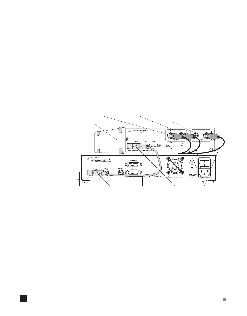
Figure 2–1
Rear view of a NIBP
Controller on a PowerLab,
showing the connections
that have been made
Pulse Signal Out
(to PowerLab Input)
NIBP Controller
PowerLab I2C cableI2C Output I2C Input BNC cables
Pressure Signal Out
(to PowerLab Input)
Optional Trigger input
(from PowerLab
analog Output)
Optional Trigger output
(to PowerLab external
Trigger input)
With BNC cables, connect the Pulse Signal Out socket on the back of
the NIBP Controller to one of the analog inputs on the front of the
PowerLab and connect the Pressure Signal Out socket on the back of
the NIBP Controller to another of the analog inputs of the PowerLab.
Both these connections must be made to determine blood pressure.
Optional Trigger Controls
18
The NIBP Controller has two control signal sockets on the rear panel.
The Trigger In is used to start an NIBP measurement cycle from an
external source such, as the PowerLab. By connecting this input to
either the analog output or digital output (if supported) of your
PowerLab you can get the LabChart or Scope software to
automatically start the NIBP Controller at preset times.
NIBP Controller Owner’s Guide

The Trigger Out is an output from the NIBP Controller that produces a
5 V signal during the measurement cycle. This can be connected to the
Trigger input of the PowerLab to control the duration of recording, or
to start LabChart or Scope recording when the cycle is started.
Both these controls are optional and allow much more automation of
the recording process, if desired or required.
Connecting to Other ADInstruments Front-ends
The NIBP Controller is designed to be used with other ADInstruments
front-ends. The NIBP Controller can be used anywhere in the series of
I2C connections, as long as there are enough analog inputs on your
PowerLab to support the required number of signals of the front-ends.
Power-up Test
Follow these steps to perform a power-up test of the NIBP Controller:
1. Connect your NIBP Controller to your PowerLab, as above.
2. Turn on your PowerLab. The Power indicator should light.
3. The NIBP Controller Power indicator should also light and the
Status indicator should be off.
Recording with the NIBP Controller
Follow these steps to begin recording with the NIBP Controller:
1. Once the NIBP Controller is connected to your PowerLab as
described above and as shown in Figure 2–1, connect the pressure
cuff to the Cuff connection on the front of the NIBP Controller, and
connect the pulse transducer to the Pulse Input connector.
Connect the pressure cuff and pulse transducer to the mouse or
rat. A typical experimental setup is shown in Figure 2–2.
2. Perform a power-up test of the NIBP Controller, described above.
3. Select the appropriate filter setting using the Filter Setting switch
on the front panel of the NIBP Controller, and set your maximum
cuff inflation pressure, by using the switch on the rear panel.
4. Open LabChart on your computer and set it up for the two
channels attached to the NIBP Controller; one channel for the
pulse signal, and the other for pressure. The pulse channel range
should be set to 50 mV. The pressure channel range should be set
to 1 V, and Units Conversion should be set up to give 0 V = 0
mmHg and 1 V = 300 mmHg.
Chapter 2 Using the Controller
19

Figure 2–2
The NIBP Controller and
PowerLab set up for use
with tail cuff, pulse
transducer and animal
restraint cage
A
D
IN
S
T
RU
ME
N
T
S
N
I
B
P C
on
t
r
ol
l
er
C
uf
f
Pu
l
s
e Input
Pu
l
s
e Rang
e
(B
PM)
S
ta
r
t
S
to
p
4
0 -
1
5
St
a
tu
s
Po
w
er
0
9
0 - 420
240
-
6
00
Tail cuffAnimal restraint cage
5. Click the Start button in LabChart to begin recording.
6. Push the Start/Stop button on the front of the NIBP Controller to
begin a measurement cycle. The pump should start and the cuff
should inflate. Observe that the pressure waveform climbs up to
the preset maximum cuff pressure. At some point in the inflation
cycle you should see the pulse signal start to decrease in
amplitude as the cuff starts to occlude the blood flow.
20
When the maximum cuff pressure is reached, the pump will stop and
the pressure will begin to drop. The pressure will drop until it reaches
about 40 mmHg at which point an valve is opened to release the
remaining air quickly. As the pressure drops the pulse signal will start
to increase again. Typical data is shown in Figure 2–3.
Connecting Pulse Transducers
The Pulse Input connector (Figure 1–1) on the front panel is a 6 pin
DIN type connector allowing attachment of the pulse transducer in
the MLT125M (mice) or MLT125R (rats) Pulse Transducer and
Pressure Cuff assemblies. Your NIBP system will have been purchased
with one of these assemblies. They are also available separately if you
require a replacement, or wish to study both mice and rats.
NIBP Controller Owner’s Guide

Figure 2–3
Typical recording using
LabChart showing the
pulse and pressure signals
Cuff Inflation Cuff Deflation
Indirect Blood Pressure Measurements in Small Animals using Tail Cuffs
Background Information
This technique has been used routinely for the non-invasive
measurement of blood pressure in rats, and more recently in mice. The
technique provides a good estimate of actual systolic pressure.
Although non-invasive, the protocol details related to the technique
(warming, handling, restraint and so on) will inevitably have some
effect on the actual blood pressure. The technique is useful as a
comparative measurement, particularly when carried out on a wellhabituated animal.
The major advantage of the PowerLab approach to this technique is
that it provides an accurate and permanent record of the pulsatile data
recorded from the tail during the measurement cycle. It therefore
makes it possible for scientists to develop protocols and detection
algorithms that correlate with their experiment. We do not offer a
method of estimating diastolic pressure, because to date very little
published data is available on the efficacy of such methods.
Chapter 2 Using the Controller
21

Users are presented with all the information that is typically recorded
by NIBP systems and can implement their own algorithms.
The following guidelines are provided to assist in the development of
protocols and reliable algorithms for the non-invasive measurement of
blood pressure in small animals.
Protocol Development Guidelines
1. Training: Most animals require some training, habituation to the
protocol, and careful handling to produce repeatable results; rats
are more readily trained than mice. Two to three training sessions
may be necessary to acclimatize the animals. Even when the
animal has been trained it may take a few minutes before a distinct
pulse is measurable on the tail.
2. Restraint cages: These are necessary for conscious animals. Ensure
that Perspex restraint cages are selected to fit the animal
comfortably. Place the animal in the Perspex cylinder restraint cage
and adjust the depth to restrict forward and backward movement
within the tube. The tube should prevent the animal from turning
around.
3. External stimuli: Sudden motion and sounds should be restricted
as much as possible, since they cause animal movement. It
sometimes helps to cover the restraint cage with a cloth to reduce
the impact of external stimuli.
22
4. Temperature maintenance: Warming rats and mice improves blood
circulation in the tail and the signal to noise ratio in the recording.
Typically animals should be preheated to 28–30 ˚C and maintained
at that temperature during the test.
5. Tail cuff: The tail cuff is used to occlude blood flow in the tail and
thereby interrupt the pulse that is measurable in the caudal artery.
The tail cuff is positioned at the proximal end of the tail.
6. Pulse transducer positioning: The active site of the pulse
transducer should be located on the ventral surface of the tail,
directly below the caudal artery. The transducer is positioned
directly following the tail cuff. Maximum sensitivity is achieved
when the artery is positioned above the most sensitive position on
the transducer. Movement from this position can reduce the
amplitude of the measured pulses.
NIBP Controller Owner’s Guide

7. Mechanical vibrations: The transducer used to make the pulse
measurements is very sensitive and subject to vibrations. Ensure
that mechanical vibrations from other laboratory devices do not
affect the transducer.
8. Measured signals: The basic signals recorded by the ML125 NIBP
system are the cuff pressure and the caudal artery pulse.
Cuff pressure is an accurate high level signal with noise of less
than +/– 0.1 mmHg and absolute error of less than +/– 2 mmHg
(after calibration). This data is used in association with the
reappearance of the caudal artery pulse to determine the systolic
pressure.
The caudal artery pulse is a low level pulse requiring significant
amplification—this is particularly true of mice. The signal is
therefore mixed with noise, and subject to movement and
respiratory artifacts. The signal amplitude may alter significantly
as the animal moves and repositions the transducer in relation to
the caudal artery.
A significant feature of the caudal artery pulse is its frequency. For
a conscious rat this is typically in the range 200–500 BPM. For a
given set of circumstances this frequency is relatively constant. The
user should be aware of this frequency, as it will be useful in later
analysis.
A sampling rate in the range of 100 – 1000 samples per second will
be adequate for pulse measurements.
Movement and respiratory artefacts in tail pulse measurements are
particularly disruptive because they often occur at times
coincident with actual measurements. However, it should be noted
that the technique is dependent not on the amplitude of the pulse,
but rather its onset.
9. Systolic measurement: Systolic measurement can normally be
made with relative ease. Systolic blood pressure (SBP) occurs when
the cuff pressure corresponds to the restoration of the first caudal
artery pulse. The presence of noise will inevitably introduce some
uncertainty in this estimate, but typical SBP measurements will be
within 5% of direct blood pressure measurements. Repeat each
measurement five to six times to ensure reproducible results are
being obtained.
Chapter 2 Using the Controller
23
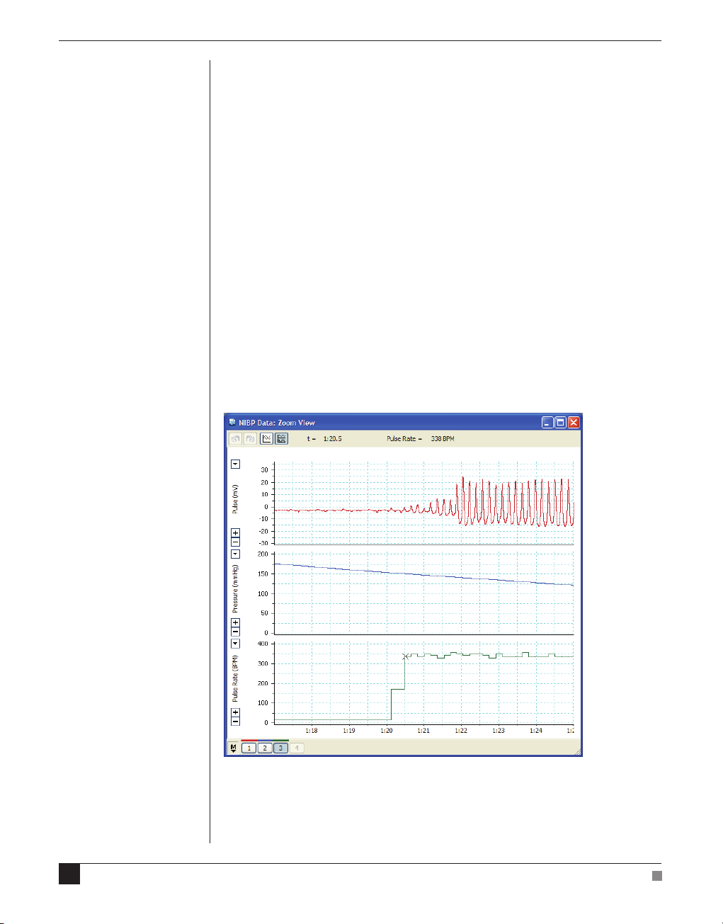
Figure 2–4
Measurement of tail pulse
rate using the Rate function
of Cyclic Measurements.
In Zoom View, the cursor is
used to display a data value
at a specific time point
(the value of the selected
channel is displayed above,
along with the time point)
Although direct observation of the pulse is usually sufficient to
determine the systolic blood pressure point, alternative methods of
detecting the onset of the pulse (by performing certain calculations
in LabChart on the pulse signal) are also available, and may in
some circumstances be used effectively:
a. RMS measurement of pulse: This can be done using the RMS
function in the Data Pad and can be useful in providing a direct
measurement of pulse energy. An averaging period of about 500
ms to 1 second is useful.
b. Cyclic height: The Cyclic Measurements ‘Height’ function allows
an offline measurement of cycle height. This is particularly useful
when the pulse amplitude is modulated by a respiratory artefact.
c. Ratemeter: The Cyclic Measurements ‘Rate’ function can be set up
to accurately measure and display the tail pulse rate, and to
directly indicate the position of the systolic blood pressure point
(as shown in Figure 2–4).
24
NIBP Controller Owner’s Guide

APPENDIX
A Technical
Details
A
This appendix describes some important technical aspects of the NIBP
Controller operation. You do not need to know this material to use the
NIBP Controller. It is likely to be of interest to the technically-minded
and is not intended in any way as a service guide.
It should be noted that any modification or attempt to service your
NIBP Controller voids your rights under the warranty.
Appendix A Technical Details
25

How it Works
The NIBP Controller is a microprocessor controlled pump, designed to
perform the cuff inflation and deflation sequence required for noninvasive blood pressure measurement. Internal amplifiers and filters
are provided to allow monitoring of the cuff pressure and the subject’s
pulse so that systolic and diastolic pressure can be determined.
Circuit Principles
To understand the internal operation of the NIBP Controller, refer to
Figure A–1, which shows a block diagram of the system.
Figure A–1
Block diagram of the
NIBP Controller
Status
indicator
Start/Stop
button
Cuff
Pulse Input
valve
Quick release
Pump
Pressure
Transducer
Internal
valve
Internal cuff
Slow release valve
cuff
Bandpass
filter
Microprocessor
Trigger
Out
Trigger
In
Pressure
Signal
Out
Pulse
Signal
Out
26
Pulse Range
switch
NIBP Controller Owner’s Guide

Pump Control
Control over the cuff inflation and deflation sequence is achieved
using an internal microprocessor. The microprocessor waits until it
detects a start signal either from the front Start/Stop button or from
the external trigger input. It then turns on the internal pump and
starts to fill the cuff. While pumping, it continuously monitors the cuff
pressure and compares it to the maximum cuff pressure set on the
back panel switch (either 200 mmHg or 280 mmHg). When this
maximum cuff pressure is reached, the pump is switched off. The air
in the cuff is allowed to escape at a predefined rate through a small
release valve. The pressure will continue to decrease until it reaches
about 35–40 mmHg, at which point a quick release solenoid will be
opened to quickly release the residual air.
The inflation and deflation cycle can be stopped (or reset) at any time
by pressing the Start/Stop button during the cycle. The
microprocessor then opens the quick release valve and the pressure
will return quickly to atmospheric. This takes about a second.
Pressure and Pulse Monitoring
In order to determine the systolic pressure the NIBP system provides
two analog output signals for animal pulse and cuff pressure.
An internal pressure transducer is used to monitor the air pressure in
the cuff air supply line. The output of the transducer is amplified and
then provided as a signal from the rear panel on the controller. The
NIBP Controller is factory calibrated to produce 1 volt output per
300 mmHg, with zero volts corresponding to zero pressure.
The pulse signal is recorded via the Pulse Input connection on the
front panel of the NIBP Controller. This input connection is designed
to allow different types of pulse transducers to be connected,
depending on the application. For rats and mice the pulse transducer
is incorporated with the tail cuff. The signal from the external pulse
transducer is amplified and then band-pass filtered, before being
passed to the pulse output connector on the rear panel.
Pulse signal filtering is achieved using a band-pass filter with preset
frequencies depending on the Pulse Range setting on the front panel.
The band-pass filter consists of an analog, second order (two pole)
high-pass filter followed by an eighth order (switched capacitance)
low-pass filter.
Appendix A Technical Details
27

The Pulse Input Connector
This connector has provision for two types of analog input: a
differential high-gain signal, or a single-ended low-gain signal. The
differential input is used for small signals typically obtained from
pulse transducers connected to rats and mice. The single-ended low
gain input can be used for other pulse transducers that provide a
larger signal. The pin assignments for the Pulse Input connector are
shown in Figure A–2.
Figure A–2
The Pulse Input connector
pin assignments
Ground
Low gain input
High gain input +
3
2
1
Low gain ground
4
6
5
+ 5V
High gain input –
The Pulse Input connector provides a +5 V power supply (pin 6),
which supplies excitation to the transducer, if required.
For transducers that produce very low level signals, such as those
used for rats or mice, the high-gain differential inputs are used (pins 4
and 5). The output signal from the transducer should not exceed
250 μV. The output of the transducer should be connected between the
high gain input + and high gain input – pins. To minimise noise, pins
1 and 2 should be shorted together.
28
For high output pulse transducers (up to 500 mV) you should use the
single-ended low gain input (pins 1 and 2). If using this connection
you should also ensure that pins 3, 4 and 5 are shorted together.
NIBP Controller Owner’s Guide

B
APPENDIX
B Specifications
Cycle Operation
Max Inflation Pressure: 200 or 280 mmHg (switch-selectable)
Measurement Cycle Time:
40–150 BPM (large animals): 44 s (for 200 mmHg)
90–420 BPM (rats): 22 s (for 200 mmHg)
240–600 BPM (mice): 18 s (for 200 mmHg)
87 s (for 280 mmHg).
41 s (for 280 mmHg).
40 s (for 280 mmHg).
Appendix B Specifications
Cycle Control: Microprocessor based. Performs inflation,
deflation, and fast deflation sequences
automatically.
Operation Indication: Trigger output (normally low, but high during
inflation and deflation cycle).
Front panel Status indicator shows inflation
and deflation operation.
Operation Abort: The cycle can be terminated at any point by
pressing the front panel Start/Stop button
again. Pressure is automatically released.
Fast Release Time: ~1.2 s from 280 to 40 mmHg at 40–150 BPM
~0.5 s from 280 to 40 mmHg at higher ranges.
Control Sources: Front panel push button; External signal source
(voltage level); Remote contact closure.
Manual Start/Stop Input
Operation: Contact the closure input for starting or
stopping measurement cycle. Shorting the
input signal results in a start or stop operation.
Minimum Contact Closure: 1 ms
29

Remote Trigger Input
Operation: Voltage level input for starting or stopping
Input Voltage: 3–5 V
Minimum Trigger Pulse: 1 ms
NIBP cycle. TTL compatible input. High level
operates a start/stop.
Trigger Output
Operation: High (+5V) output level during measurement
cycle. Otherwise zero.
Pressure Output (Cuff Pressure)
Sensitivity: 0–1 V : 0–300 mmHg (factory calibrated)
Frequency Response: DC to 10 Hz
Pulse Input
Input Impedance: Differential Input: 10 GΩ
Input Signal Range: High gain differential input: (0–25 μV) up to
Single-ended Input: 1 MΩ
(0–75 μV), depending on rear panel Gain Adj
setting.
Low gain single-ended input: (0–50 mV) up to
(0–150 mV), depending on rear panel Gain Adj
setting.
30
Bandwidth: 40–150 BPM: 0.7–2.5 Hz
90–420 BPM: 3–7 Hz
240–600 BPM: 4–10 Hz
Pulse Output Max: ± 5 V
Operating Requirements
Power Requirements: PowerLab or MacLab I2C interface:
+9 V @ 100 mA
±18 V @ 50 mA
Operating Conditions: 5–35 °C, 0–90% humidity (non condensing)
Physical Configuration
Dimensions (h × w × d): 65 mm × 200 mm × 275 mm (2.56" × 7.9" × 10.8")
Weight: 1.7 kg
ADInstruments reserves the right to alter these specifications at any time.
NIBP Controller Owner’s Guide

Index
B
back panel 15
block diagram
26
C
circuit principles 26
cleaning
connecting
Cuff pressure connection
10
pulse transducers
to other front-ends
to other recorders
to PowerLab
18
20
19
19
F
filter switch 15
front panel
14
G
gain adjustment 16
H
how it works 26
I
14
M
maintenance 10
maximum cuff pressure switch
P
Power indicator 14
power up testing
PowerLab connection
pressure and pulse monitoring
pressure output connection
Pulse Input connector
pulse input gain adjustment
pulse output connection
Pulse Range switch
pump control
19
18
16
15, 28
16
15, 16
15
27
S
Safety Notes 5–11
Start/Stop button
Status indicator
storage
10
15
14
T
Trigger controls 18
trigger input connection
trigger output connection
16
16
16
27
indicators
Power
14
Status
14
Indirect blood pressure measurements
I2C connection
Index
15
21
U
user modification voids warranty 25
using the NIBP Controller
19
31

32
NIBP Controller Owner’s Guide
 Loading...