

Page 1

AML/J
Operator
Guide
Page 2

Copyright © 1998 ADIC/GRAU Storage Systems GmbH&Co.KG
All rights reserved.
This document may be reproduced or transmitted neither in excerpts nor completely in any form
with any media (neither electronically nor mechanically, including photocopying and recording)
and by no data storage or recall system with the excepti o n of an approva l on the part of ADIC /
GRAU Storage Systems.
ADIC/GRAU Storage Systems reser ves the ri ght to correc t, to updat e or to modify the informa tion
contai ned in this document.
DAS is a registere d trade mark of ADIC /G RAU Storage System s Gmb H
DAS is a trade mark of ADIC/GRAU Storage Systems GmbH
Other trade marks are the property of the relevant owner.
Document number: DOC D00 025-A
Published on: March 31, 1999
ADIC/GRAU Storage Systems GmbH&Co.KG • Eschenstra ße 3 • D-89558 Böhmenkirch
Page 3

Contents
1 Introduction
1.1 Contents . . . . . . . . . . . . . . . . . . . . . . . . . . . . . . . . . . . . . . . . . . . 1-1
1.2 Target group . . . . . . . . . . . . . . . . . . . . . . . . . . . . . . . . . . . . . . . . 1-1
1.3 Layout of the Guide . . . . . . . . . . . . . . . . . . . . . . . . . . . . . . . . . . 1-1
1.4 Further documentation. . . . . . . . . . . . . . . . . . . . . . . . . . . . . . . . . 1-2
1.5 Explanation of the symbols and notes . . . . . . . . . . . . . . . . . . . . 1-2
1.6 Technical support . . . . . . . . . . . . . . . . . . . . . . . . . . . . . . . . . . . . 1-3
1.7 Product observation. . . . . . . . . . . . . . . . . . . . . . . . . . . . . . . . . . . 1-4
2 Description of the system
2.1 Overview of the system components . . . . . . . . . . . . . . . . . . . . . 2-1
2.2 Host connection . . . . . . . . . . . . . . . . . . . . . . . . . . . . . . . . . . . . . 2-1
2.3 Description of function . . . . . . . . . . . . . . . . . . . . . . . . . . . . . . . . 2-2
2.4 Functional units . . . . . . . . . . . . . . . . . . . . . . . . . . . . . . . . . . . . . 2-2
2.4.1 Drives . . . . . . . . . . . . . . . . . . . . . . . . . . . . . . . . . . . . 2-3
2.4.2 Control cabinet . . . . . . . . . . . . . . . . . . . . . . . . . . . . . 2-3
2.4.3 AML Management Unit (AMU) . . . . . . . . . . . . . . . 2-3
2.4.4 Storage cells . . . . . . . . . . . . . . . . . . . . . . . . . . . . . . . 2-5
2.4.5 Handling unit . . . . . . . . . . . . . . . . . . . . . . . . . . . . . . 2-6
2.4.6 I/O unit . . . . . . . . . . . . . . . . . . . . . . . . . . . . . . . . . . . 2-7
2.5 Cartridges . . . . . . . . . . . . . . . . . . . . . . . . . . . . . . . . . . . . . . . . . . 2-7
Page 4

2.6 Technical Data . . . . . . . . . . . . . . . . . . . . . . . . . . . . . . . . . . . . . . . 2-8
2.6.1 Electrical system . . . . . . . . . . . . . . . . . . . . . . . . . . . 2-9
2.6.2 Noise . . . . . . . . . . . . . . . . . . . . . . . . . . . . . . . . . . . . 2-9
2.6.3 Climatic conditions . . . . . . . . . . . . . . . . . . . . . . . . . 2-9
3Safety
3.1 Use as intended. . . . . . . . . . . . . . . . . . . . . . . . . . . . . . . . . . . . . . 3-2
3.2 Warning indications . . . . . . . . . . . . . . . . . . . . . . . . . . . . . . . . . . 3-3
3.3 Scope. . . . . . . . . . . . . . . . . . . . . . . . . . . . . . . . . . . . . . . . . . . . . . 3-5
3.4 Protective devices . . . . . . . . . . . . . . . . . . . . . . . . . . . . . . . . . . . .3-5
3.4.1 System access . . . . . . . . . . . . . . . . . . . . . . . . . . . . . 3-5
3.4.2 Mechanical lock. . . . . . . . . . . . . . . . . . . . . . . . . . . . 3-5
3.4.3 Main switch . . . . . . . . . . . . . . . . . . . . . . . . . . . . . . . 3-5
4Operation
4.1 Switches on the control cabinet . . . . . . . . . . . . . . . . . . . . . . . . . . 4-1
4.2 Starting the AML/J system . . . . . . . . . . . . . . . . . . . . . . . . . . . . . 4-3
4.3 Stopping the AML/J system . . . . . . . . . . . . . . . . . . . . . . . . . . . .4-4
4.3.1 Normal stopping . . . . . . . . . . . . . . . . . . . . . . . . . . . 4-4
4.3.2 Emergency shutdown. . . . . . . . . . . . . . . . . . . . . . . . 4-5
4.4 Restarting the AML/J system . . . . . . . . . . . . . . . . . . . . . . . . . . .4-6
4.5 Manual operating mode . . . . . . . . . . . . . . . . . . . . . . . . . . . . . . . 4-7
4.6 Switching over to Dual-AMU . . . . . . . . . . . . . . . . . . . . . . . . . . 4-8
5 Menus and commands
5.1 Application . . . . . . . . . . . . . . . . . . . . . . . . . . . . . . . . . . . . . . . . . 5-1
5.1.1 Layout of the menu bar . . . . . . . . . . . . . . . . . . . . . . 5-2
5.1.2 Selecting a command. . . . . . . . . . . . . . . . . . . . . . . . 5-2
5.1.3 Change size of the windows . . . . . . . . . . . . . . . . . . 5-3
5.1.4 Move windows. . . . . . . . . . . . . . . . . . . . . . . . . . . . . 5-3
5.1.5 Close window . . . . . . . . . . . . . . . . . . . . . . . . . . . . . 5-3
5.2 Menu overview . . . . . . . . . . . . . . . . . . . . . . . . . . . . . . . . . . . . . . 5-4
5.3 Shutdown menu . . . . . . . . . . . . . . . . . . . . . . . . . . . . . . . . . . . . . 5-5
ii Contents
DOC D00 025-A
Page 5

5.4 Edit menu . . . . . . . . . . . . . . . . . . . . . . . . . . . . . . . . . . . . . . . . . . 5-7
5.5 View menu . . . . . . . . . . . . . . . . . . . . . . . . . . . . . . . . . . . . . . . . . 5-8
5.5.1 Archive. . . . . . . . . . . . . . . . . . . . . . . . . . . . . . . . . . . 5-8
5.6 Operations menu . . . . . . . . . . . . . . . . . . . . . . . . . . . . . . . . . . . . 5-19
5.6.1 Operator login . . . . . . . . . . . . . . . . . . . . . . . . . . . . 5-19
5.6.2 Manual Operation . . . . . . . . . . . . . . . . . . . . . . . . . 5-20
5.6.3 Disaster Recovery . . . . . . . . . . . . . . . . . . . . . . . . . 5-22
5.7 Admin menu . . . . . . . . . . . . . . . . . . . . . . . . . . . . . . . . . . . . . . . 5-23
5.7.1 Administrator Login . . . . . . . . . . . . . . . . . . . . . . . 5-23
5.8 Window menu . . . . . . . . . . . . . . . . . . . . . . . . . . . . . . . . . . . . . .5-24
5.9 Help menu . . . . . . . . . . . . . . . . . . . . . . . . . . . . . . . . . . . . . . . . . 5-25
6 Processing media
6.1 Overview . . . . . . . . . . . . . . . . . . . . . . . . . . . . . . . . . . . . . . . . . . . 6-1
6.2 I/O unit/C . . . . . . . . . . . . . . . . . . . . . . . . . . . . . . . . . . . . . . . . . . .6-3
6.2.1 Inserting cartridges . . . . . . . . . . . . . . . . . . . . . . . . . 6-4
6.2.2 Ejecting cartridges . . . . . . . . . . . . . . . . . . . . . . . . . . 6-5
6.3 I/O unit/D (HICAP) . . . . . . . . . . . . . . . . . . . . . . . . . . . . . . . . . . 6-6
6.3.1 Inserting cartridges . . . . . . . . . . . . . . . . . . . . . . . . . 6-7
6.3.2 Ejecting cartridges . . . . . . . . . . . . . . . . . . . . . . . . . . 6-8
6.4 I/O unit/E . . . . . . . . . . . . . . . . . . . . . . . . . . . . . . . . . . . . . . . . . . 6-9
6.4.1 Inserting cartridges . . . . . . . . . . . . . . . . . . . . . . . . . 6-9
6.4.2 Ejecting cartridges . . . . . . . . . . . . . . . . . . . . . . . . . 6-10
6.5 Disaster Recovery. . . . . . . . . . . . . . . . . . . . . . . . . . . . . . . . . . . 6-11
March 31 , 1999
iii
Page 6

iv Contents
DOC D00 025-A
Page 7

1 Introduction
1.1 Contents
This Guide contains information and instructions for the safe operation
of the AML/J syste m.
1.2 Target group
This Guide is written for users who work with the AML/J.
1.3 Layout of the Guide
The Guide is broken down into the following chapters:
Chapt er 1 Introduction - Notes on the use of the Guide
Chapt er 2 Overview - Contains general information on the
AML/J components.
Chapt er 3 Safety - Describes the danger symbols, mes-
sages, safety functions and consider ations for
the safe opera tion of the AML/J.
Chapt er 4 Operation - Describ es the functions for switch-
ing the AML/J on and off.
Chapt er 5 Menus a nd com m ands - Describes the menus
and the commands executed by the AML/J.
Chapt er 6 Processing media - Describes t he I/O unit an d its
use.
Index
March 31 , 1999
1-1
Page 8
1.4 Further documentation
DOC D00 024 AML/J Maintenance Guide
DOC D00 014 AML/J Software Backup
DOC D00 007 AML/J Installation Guide
DOC E00 003 AMU Installation Guide
DOC E00 007 AMU Problem Determination Guide
DOC E00 014 AML Controller User Guide
DOC E00 005 AMU Reference Guide
1.5 Explanation of the symbols and
notes
The following s ymbols and notes draw your attent ion to important i nformation.
!
For detailed explanation of the symbols see Warning indic ations on page
3-3.
<1>+<2> Press keys simultaneously
italics Heading, e.g. Chapter 3, Safety
File name, e.g. dasdata.ini
Variable, e.g. clie nt_name
&KLFDJR
bold Special term, e.g. Scratch-Pool
courier Lines or terms in an input window
[courier] Optional parameters
Param1 | Param2 Alternative parameters
☞ Reference
Term appearing on the workspace of the AMU
- Program message
- Command
- Parameter or file
1-2 Introduction
DOC D00 025-A
Page 9
1.6 Technical support
!
!
Warning
The use of the AML/J by untrained personnel can lead to dangerous
situations. The consequence can be severe to lethal injuries due to
moving or current-conducting parts. For this reason an introductory
course at ADIC/GRAU is recommended for all persons who handle the
AML/J.
The operator is responsib le that the followi ng functi ons are perfo rmed on
the system only by qualified personnel:
• Preparation for operation
• Setting up
• Starti ng th e system
• Application
• Shutting the system down
• Maintenance
• Restart
Warning
Yo u may perfor m certai n work and adaptations y ourself only if you are
qualified for this by corresponding education and training.
It is extremely important that the user is familiar with all safety rules
before working with the system and follows them.
If you cannot solve a problem with the aid of this document or if you are interested in a recommendation regarding training, please contact your contract partner or the ADIC/GRAU Technical Assistance Center (ATAC).
ADIC/GRAU Storage Syst ems GmbH ADIC
Eschenstrasse 3 10949 East Peakview
avenue
89558 Boehmenkirch Englewood, CO 80112
Germany U.S.A.
We would be p leased to help you further.
Telefax: +49 (0) 6196-59 08 69
Email: techsup @ ad ic.com
Telephone: 1 800 827 3822 North America
+49 6142 992364 Germany
00800 9999 3822 (the rest of the world)
March 31 , 1999
1-3
Page 10

1.7 Product observation
We are legally obliged to obser ve our product s even after delivery.
Therefore please notify us about everything which is of interest to us:
• Changed setting data
• Experience with the product
• Repetitive faults
• Difficultie s with this Guide
1-4 Introduction
ADIC-GRAU Stor age S ystem s GmbH ADIC
Eschenstrasse 3 10949 East Peakview
89558 Boehmenkirch avenue
Germany Englewood, CO 80112
U.S.A.
Telefax: +49 (0) 6196-59 08 69
Email: techsup @ ad ic.com
DOC D00 025-A
Page 11

Telephone: 1 800 827 3822 North America
+49 6142 992364 Germany
00800 9999 3822 (the rest of the world)
March 31 , 1999
1-5
Page 12

1-6 Introduction
DOC D00 025-A
Page 13
2 Description of the system
2.1 Overview of the system components
Storage media such as magneti c tape cartr id g e s, optical disks and CDROMs are broug h t a u tomati c a l l y i n to th e a ss ociat e d d ri v e s an d fetche d
from there again with the AML/J. The storage media are brought to the
drives with the aid of software in the host and in th e AML/J contro l unit
and discharged from these drives again.
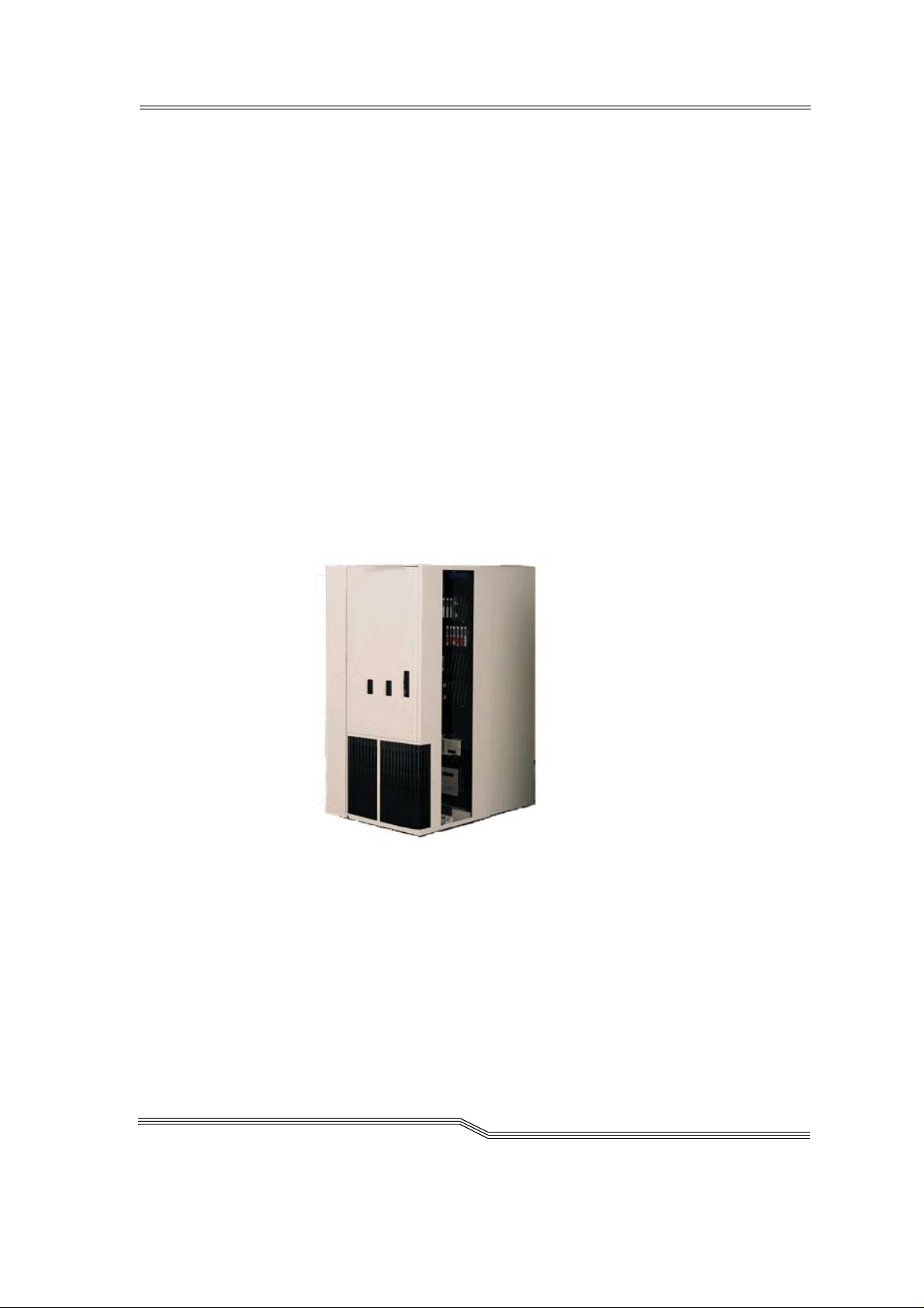
The AML/J is a modul ar system and consists of
• a basic module
− Handling unit
− Storage racks
− Control cabinet
− I/O unit (E/I/F)
• up to 9 extension modules (optional)
− Storage racks
− I/O unit (E/I/F)
March 31 , 1999
Figure 2-1: AML/J basic module
2.2 Host connection
AML/J is connected through the AMU (AML Management Unit) to one
or several hosts. The possi b ilitie s of the conn ect ion are describe d in the
AMU Reference Guide.
2-1
Page 14

2.3 Description of function
The AML/J syste m can be instal led on the unfin ished floo r or on a false
floor .
The handling unit moves the cartridges between the storage cells, drives
and the I/O unit. The handling unit has a gripper. A barcode scanner on
the gripper identifies the cartridges at the compartments in the archive.
Further details are de scribed under Handling unit on page 2-6. The cartridges can be brought into the AML/J system or moved out from the
system with the aid of the I/O unit without inte rrupti ng the work.
Additional details are described under I/O unit on page 2-7.
Manual access to the compartments in the archive, the handling unit and
the dri ve s is through an access door after switching off the power supply.
The cartridges in the AML/J are moved by host requests. Primary
requests are for mounting and discharging cartridges in the drives and
for inserting/ejecting cartridges into/out from the AML/J.
Each cartridge can have an external machine and user readable label to
identify the cartridge in the AML/J at stocktaking and when adding a
cartridge to the AML /J. The AMU stores the p hysical s torage location of
the cartridge in a database which is based on the Volser (Volume Serial
Number).
Apart from the commands for moving the tape cartridges, the host can
also reque st stat us, con figurat ion an d cartrid ge storage i nfor mation fr om
the AML/J control unit.
2-2 Overview
2.4 Functional units
The A M L/J syst e m consists of the f ollowi n g functi o n a l u ni t s:
• Drives
• Control cabinet with:
• AML/J control unit
• AMU (AML Managemen t Unit)
• Stora g e c el ls ( l in e a r ra c k s)
• Handling unit
• I/O units
DOC D00 025-A
Page 15
2.4.1 Drives
The AML/J system supports a large number of drives for different storage media.
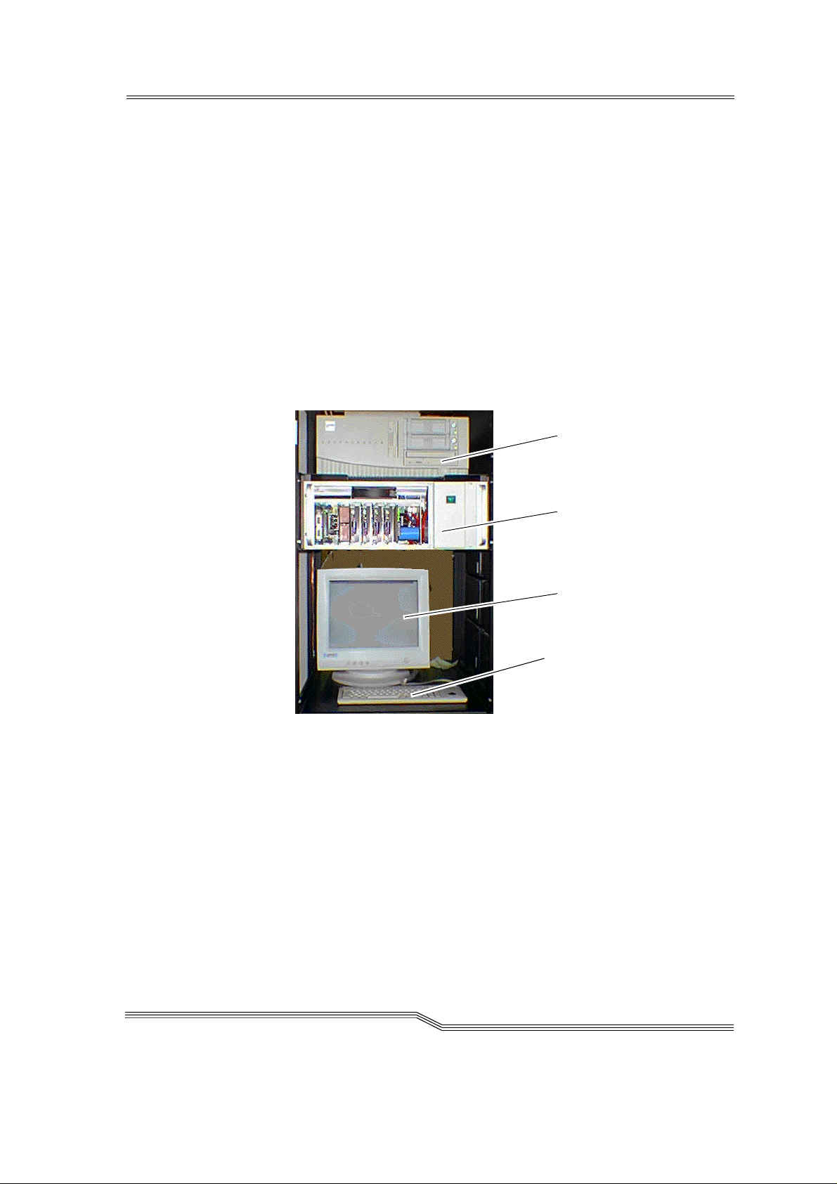
2.4.2 Contr ol cabinet
The control unit of the system is housed in a control cabinet. This control
cabin e t co ntains :
• AMU PC
• Control unit
− Power supply
− Motor cont rol
− Interfa ce conve rt er
− Safe ty system
• Drive(s) (optional)
AMU PC
Control un it
Figure 2-2: Control cabinet
2.4.3 AML Management Unit (AMU)
The AMU is the control processor for the AML system. In the normal
mode the host com puter sen ds th e c omman ds to th e AMU f or c on tro lli ng
the system. The AMU is located next to further power supply components in the control cabinet Figure 2-2: on page 2-3.
It is possible to connect a second AMU PC in parallel to back up against
failures due to failures of the PC hardware. This redundant version is
called Dual-AMU, and a few cables have to be reconnected for the
change.
AMU monitor
Keyboard
March 31 , 1999
2-3
Page 16

Hardware components
The AMU hardware consists of:
• A computer (AML controller) with screen, keyboard and trackball or
mouse
• Programmable Multi-Axis Controller (PMAC board)
• Network board (Token Ring, Ethernet or FDDI)
Software components
The AMU software components are:
• Operating system OS/2
• Communication Manager/2 , TCP/IP
• Database Manage r/2
• AML Management Software (AMS)
Tasks of the AMU:
• Host communication
− interprets the commands coming from the host computer
− checks these commands for executab ility
• Archive catalogue administration
− stores the logical coordinates of the compartments
− assigns the cartridges to the compartments
− knows the status of compartments and drives
− stores information on scratchpool administra tion
• Conversion of the logical coordinates into physical coordinates
• Commu n ication with the con t rol unit
• User interface
− for start-up
− for service
− for the opera to r
• Configuration (describes the individual structure of the archive)
2-4 Overview
Information
The AMU does not register the data contents of the cartrid ge s.
DOC D00 025-A
Page 17
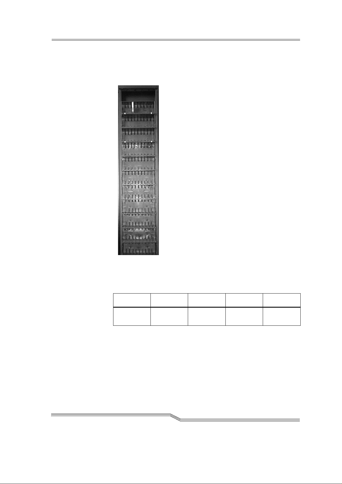
2.4.4 Storage cells
The AML/J system contains compartments (storage cells) in linear racks
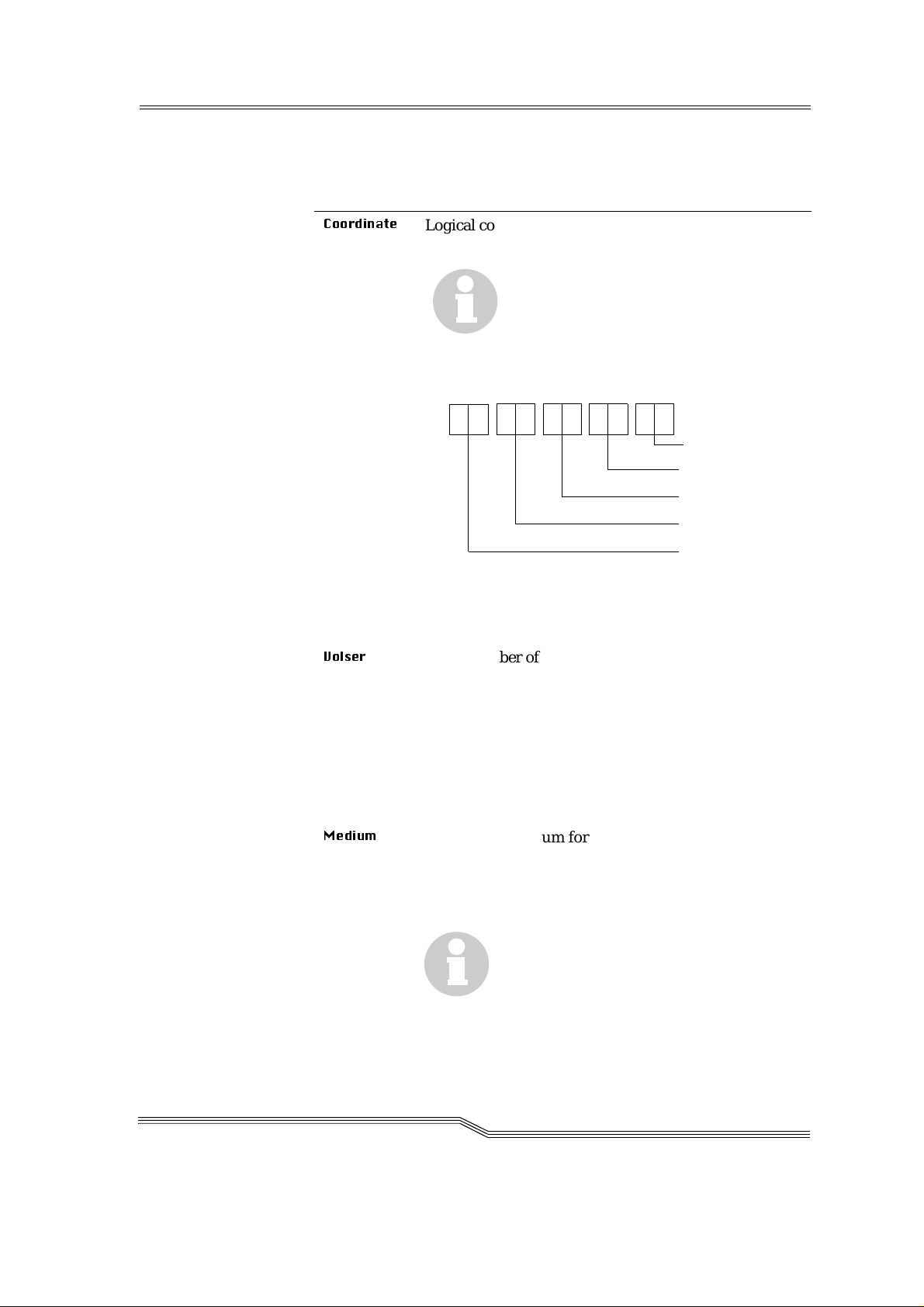
(stationary storage segments (☞ Figure 2-3: ). Table 2-1: Coordinates of
the storage cells on page 2-5 contains the coordinates of the storage cells.
March 31 , 1999
Figure 2- 3: Example of storage cells
Table 2-1: Coordinate s of the storage cells
L3 - LD 01 - 99 01 01 - 99 01 - 99
Type Module Segment Row Compart-
ment
The module number corresponds to the number of the segment whereby
the assig nmen t o f the mod ule number s to t he se gmen t can be det erm ined
by the user at start-up and the segment is always 01. The rows are
coun te d from bel ow to abo ve and the co m p a r t me nts from the left to th e
right. Optical disks occupy two comp artments in the database.
2-5
Page 18
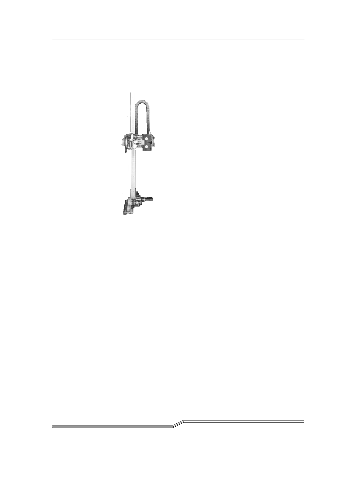
2.4.5 Handling unit
The handling unit identifies and moves cartridges between the storage
cells, d rives and th e I/ O unit.
Figure 2-4: AML/J handling unit
Access to the archive compartments and the drives is facilitated with the
handling unit. The handling unit executes the commands of the AML
Managemen t Sof tware (AMS) a nd re turns status messages as response.
The handling unit is equipped with a (laser) barcode scanner. Typical
tasks of the han dling unit are insert ing and ejecti ng cartridges, placing
and gripping cartridges in the archive, mounting the connected drives
with the cartridges and reading a barcode label attached to the cartridges.
Technical data of the handling unit
• Cartesian robot with 4 axes:
− 3 linear axes
− 1 rotary axis
• Drive with direct current servomotors
• Position measuring system (optical digital encoder) and home posi-
tion sensors
• Tran smission of the torque s with toothed dr ive belts
• Driving axis guided
− with rollers on 2 guide rods below
− by one guide rod with loose bearing (play compensation) above
2-6 Overview
DOC D00 025-A
Page 19

2.4.6 I/O unit
The I/O unit facilitates inserti ng and ejecting cartridges with ou t interrupting normal processing (☞ Figure 2-5:).
Figure 2-5: I/O unit/E
2.5 Cartridge s
Each cartridge in the AML/J system can have an external user and
machine readable label for identifying the Volsers (Volume Serial
Number). The external label contains between one and 16 characters for
the Volser. The Volser is composed of the uppercase letters A-Z and the
numbers 0-9. The AML/J system supports different types of label (e.g.
“Code 39” and “STK”).
March 31 , 1999
2-7
Page 20
2.6 Technical Data
Dimensions
Table 2-2: Size of the AML/J components
Width x depth Height
Basic module 1.00 m x 1.50 m
(3.28 ft x 4.92 ft)
Extension
module
Control cabinet
0.75 m x 0.82 m
(2.46 ft x 2.69 ft)
2.05 m
(6.73 ft)
Weight without/with cartridges (3480/3490)
Table 2-3: Weight of the AML/J components
Weight in lbs Weigh t in kg
With
media
Basic module 721 509 326 230 kg
Control cabinet - 331 - 150 kg
Extension module 688 454 311 205 kg
Without
media
With
media
Without
Maximum floor loading
Table 2-4: Floor loading of the AML/J components
media
2-8 Overview
Basic module
Extension module
390 kg/m
2
DOC D00 025-A
Page 21
2.6.1 Electrical system
Table 2-5: Electrical data of the AML/J
Tota l sy s tem conn e c tion 230 V ± 10% 1, N, PE110 V ± 10% 1, N,
Europe North America
PE
Fuses
(by customer)
Power section voltage 48 V =
Frequency 50 Hz 60 Hz
Control voltage 24 V =
Degree of protection IP 50
Heat dissipation
Maximum 1.2 kW
2.6.2 Noise
Table 2-6: Noise caused by the AML/J
Total syste m 80 dB (A)
2.6.3 Climatic conditio ns
Table 2-7: Climatic conditions for operating the AML/J
Temperature 10 .. 32 °C
16 A fuse
slow-blow
10 A fus e
slow-blow
March 31 , 1999
Humi di ty 15 .. 80%
2-9
Page 22

2-10 Overview
DOC D00 025-A
Page 23

3Safety
Information
Apart from the safety provisions in this chapter, the local and specific
technical safety regulations apply.
Avoi d h a z ar d s du ri ng main t e n a nce and in ope ratio n of th e system by
• safety-conscious behaviour
• careful actions
CAUTION!
Knowledge of and observance of these instructions are indispensable
for the safe handling of the ADIC/GRAU Storage Systems AML/J systems.
March 31 , 1999
3-1
Page 24

3.1 Use as intended
The quotati on and the order confirmation as well as the scope de f ined in
this document are part of the AML/J documentation. Any use other than
that specified in this is consider e d to be not as intende d.
This system is intended for processing:
• Magnetic tape cartridges
• Optical disks
• CD-ROMs in the CADDY housing
Any use extending beyond this is not as intended.
ADIC/GRAU Storage Systems is not liab le for damages which ari se
because of use not agreed with it - the user bears the risk alone.
The following are also included in use as intended
• Compliance with the instructions in the instructions delivered with
the system ( this Guide, Op e rator and AMU Guides)
• Complia nce with the insp e ction and maintenance regulations
3-2 Safety
DOC D00 025-A
Page 25
3.2 Warning indications
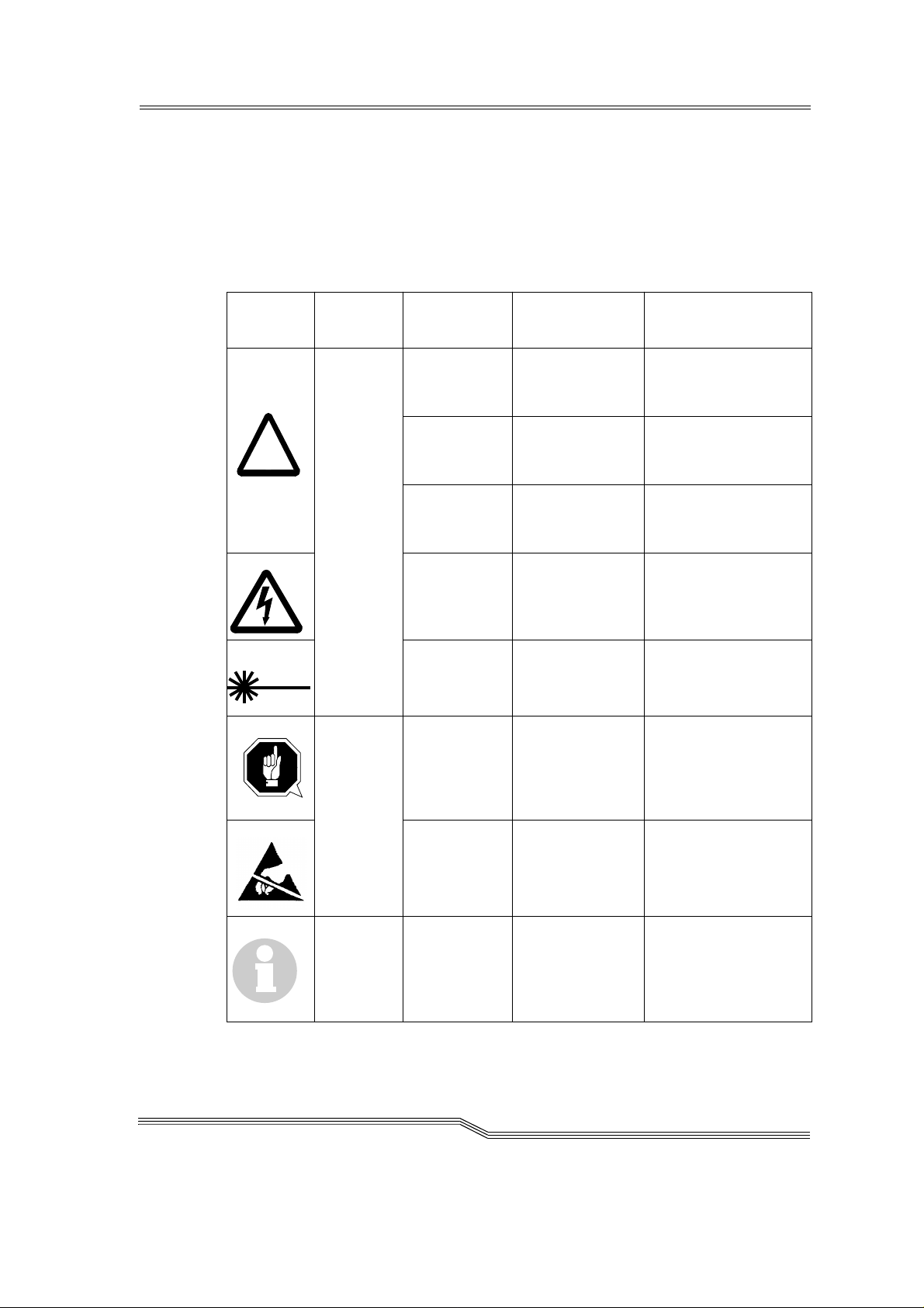
!
ADIC/GRAU classifies hazards into different categories. Ta ble 3-1 : shows the
relation betwe en symbols, signal words , a ctual hazards and possible consequences.
Table 3-1: Warning ind ications
Symbo l
Damage
to...
Persons
Signal word Definition Consequences
DANGER! Directly
threatening
danger
WARNING! Possibly
dangerous
situation
CAUTION! Less dangerous
situation
WARNING!
Dangerous
voltage!
CAUTION! Less dangerous
ATTEN-
TION!
Directly
approaching
electrical danger
situation
situation
Situation
possibly causing damage
Death or very severe
injuries (maiming)
Possibly death or
very severe inj u rie s
Possibly light or
slight injuries
Death or severe
injury
Possibly light or
medium injury
Possibly damage of
the product and its
environment
March 31 , 1999
Material
Electrostatically
sensitive
Information Application tips
Potential risk of
damage to the
electronics
and other
important/useful information
and hints
Possibly damage to
the product
No dangerous or
damagi ng consequences for persons
or things
3-3
Page 26

Especially emphasized paragraphs in this Guide warn against a hazard
!
or draw your attention to impor tan t information.
These include the following paragraphs and symbols:
In connection with the signal words of ‘Danger’ or ‘Warning’, this
symbol warns against a dangerous situation in which personal death
or severe injuries are threatening.
In connection with the signal word of ‘Caution’, the symbol warns
against a dangerous situation in which light injuries can be the consequence.
There is risk of a lethal electric shock. Electrical current is possibly
present at places identifi ed wit h this symbol. Before all work always
ensure that no electrical connections are under voltage.
Caution!
This symbol is a laser warning.
Use only the described procedures for adjusting and setting up the
laser. Injuries can be ca used by laser light if other pr ocedures are used .
This symbol refers to specific regulations, rules, instructions and
working procedures which must be observed. Nonobservation of this
symbol can result in equipment damage or destruction or other material damage.
This symbol refers to the ris k of equipment damage because of el ectro static discharges.
This symbol indicates a hint or important information for the user. No
risks of personal or material damage are connected with this symbol.
3-4 Safety
DOC D00 025-A
Page 27

3.3 Scope
!
These instructions apply for the ADIC/GRAU Storage Systems AML/J
systems.
Further safety regulations for the components used in the system are not
put out of force by these ins t ructions.
Information
The documentation of the external manufact urer s are integral part of
the AML/J documentation.
3.4 Protective devices
The AML/J system is equipped with the following protective devices:
• Moni to re d ac ce ss to the syste m
• Mechanical interlock
• Main switch
3.4.1 System acc es s
The AML/J syste m is surr oun ded comp let el y by pane llin g. Acce ss to the
system is possible only through a monitored door (or doors).
The panelling of the AML/J system separates the danger area from the
normal working area. The danger area of the system is the area in which
there is a risk of injury due to a movement of the components.
WARNING!
Movements of the mechanical components in the AML/J system can
cause severe injuries. The acc ess to the system may be opened only by
authorized personnel.
3.4.2 Mechanic al lock
The access door(s) to the sy ste m can be opened from the outside on ly
with a key. Authorized personnel are responsible for the safety of the
key.
3.4.3 Main switch
If you swit ch of f the mai n swi tch , you stop the mo veme nt elec tron ics and
separate the system from the powe r supp ly. All move men ts of the robot
are stopped immediately. Switch the main switch off immediately in the
case of risk of injury or possible material damage.
March 31 , 1999
3-5
Page 28

ATTENTION!
!
Apart from emergency situations, the AML/J system is firstly always
stopped with the normal shutdown routine before the main switch is
switched off. ADIC/GRAU Storage Systems is not liable for damages
because of actuation of the main switch in a manner not intended. The
user bears responsibility solely for this.
WARNING!
Movements of the mechanical components in the AML/J system can
cause severe injuries. Before switching on the main switch and restarting the AML/J system convince yourself that no risks for persons and
material are caused by this.
3-6 Safety
DOC D00 025-A
Page 29

4 Operation
In the normal case the host sends the commands to the AML/J. The
AMU is used by the operator for control purposes. The operator is
responsible for the following tasks:
• Starting the AML/J
• Stopping the AML/J
• Handling the cartridges
You will find information on handling th e cartridg e s under Insert ing car-
tridges on page 6-4 and Ejecting cartridges on page 6-5. In the case of
equipment disturbances the operator can process the cartridges.
4.1 Switches on the control cabinet
You will find several swit ches for swit ch ing the com pon e nts on and off
in the control cabine t. In addition to the switche s on the front of th e control unit, a mains switch is located on the back of the control unit.
Figure 4-1: Control unit on page 4-1 shows a view of the front side of the
contro l u nit.
March 31 , 1999
Main switch (S3)
Figure 4-1: Control unit
The switches on the control unit are described in Table 4-1: .
"Control on" button
(only for HICAP)
4-1
Page 30

Table 4-1: Control panel switches
Switch Description
1 Main switch S3 Switching on the main supply voltage.
WARNING!
Dangerous voltage!
The following are not in the
circuit of the main switch:
•Drives
•AMU computer
<CONTROL OFF> lights up if the control is
ready but not active.
2Only in sys-
tems
with HICA P
illuminated
pushbutton
(green)
CONTROL
ON
3Mains switch
(back of the
control unit)
The control lamp lights up after actuation.
Acti va tes the con t ro l
Prerequisites
Main switch switched on, all doors ar e closed
Switching on the line voltage including that
for AMU compu te r and monitor.
4-2 Operation
DOC D00 025-A
Page 31
4.2 Starting the AML/J system
!
Perform the f ollowing steps to start the AML/J system.
Step 1 Ensure that:
• the access doors are close d
ATTENTION!
The robot requires sufficient free space for the homing run.
All axes of the robot move during the homing run. Objects and system
parts within the range of the robot can be damaged.
Warning!
The movements of the mechanical components in the AML/J system
can cause severe injuries. Ensure before switching the main switch on
(position 1) that there are no dangers for persons or equipment.
Step 2 Switch the mains switch on the AMU PC on
The AMU PC is located in the control cabinet, above the control
unit (Figure 2-2: on page 2-3).
In syst e m s with a Dua l- AMU, ta ke car e th a t the chan ge - o ve r
switch f or the monitor, keyboard and mous e is switched to the
computer which you just switch on.
Once the initialization of the first computer is ended, switch
this swit ch over and switch the se cond comput e r on.
March 31 , 1999
Step 3 Switc h the main sw itch on (posit io n 1)
The main switch lights up green.
Step 4 Press the <System on> button
(only in systems with HICAP)
The <Co ntrol on> button lights up green
The AML/J system is supplied with power. The software in the AMU
and in the control units starts with the initialization. The status is
indicated in the AMU log.
The robot and the storage towers perform a homing run, the gripper
functions are tested in conclusi on.
Step 5 Check in the
<0700> STATUS: robot ready.
$08/RJ
that the system has started correctly.
4-3
Page 32

4.3 Stopping the AML/J system
The AML/J system can be stopped normally or switched off in an emergency.
Information
The metho d described unde r Emergency shutdown may be used only in
emergencies.
4.3.1 Normal stopping
Proceed a s follows t o stop the AML/J system normally:
Step 1 Ensure in your application
that your applicatio n is not
endangered by the shutdown
(☞ Documentati on of the
host software).
Step 2 Find the "
$089
" win-
dow on the AMU PC
• Open the "
:LQGRZ/LVW
window with the <Esc>
and <Ctrl> keys
•Mark the "
$089
".
line with the arrow keys
• Press the <Enter> key
Step 3 Click in the "
$089
"window on th e f irs t ce l l (S h utdown) with the mouse.
Step 4 Click in the now open list
on the
6KXWGRZQFRPSOHWHZLWK
line
26
"
4-4 Operation
DOC D00 025-A
Page 33

Step 5 Click with the mouse on the
"
<HV
" button in the now
open
"
727$/6<67(06+87'2:1
$08DQG26
" window
The robot ends its curr ent task
and moves into the rest
position.
Step 6 Wait until all window s are
close d a n d the mess age
"
266\VWHPLVQRZVKXW
" is displayed.
GRZQ
The process can last relatively long (5 minutes).
Step 7 Switch the mains swit ch on
the AMU PC off
(PC is located above in the
control cabinet)
Step 8 Switch the main switch off
The pow er su pply to t he AM L/J
system is switched off.
March 31 , 1999
4.3.2 Emergency shutdown
Apply the following procedure in an emergency situation.
Except for emergency situations, the AML/J system should be stopped
normally before the main switch is switched off. ADIC/GRAU Storage
Systems accepts no responsibilit y for damage because of use of the main
switch not as intended. The user bears the entire risk.
WARNING!
Dangerous voltage!
The system is not deenergized completely with the main switch.
4-5
Page 34

Step 1 Actuate the main switch
The power voltage of the AML/J is switched off. All movements of the
robot are stopped.
4.4 Restarting the AML/J system
The AML/J system is restarted as follows after an emergency shutdown.
Step 1 Rectif y all problem s whic h made sto pp ing th e AML/J syst em
necessary (if required).
Step 2 Start the AML/J system according to the procedure Starting the
AML/J system on page 4-3.
4-6 Operation
DOC D00 025-A
Page 35

4.5 Manual operating mode
This operating mode is intended if the AML/J should be operated without the robot because of a robot fault or mainten a nce. In this operating
mode the requirements are displayed in the AMU but the user performs
the actions instead of the robot.
Step 1 Shut the system down according to Stop p ing the AML/ J system
on page 4-4
Step 2 Open the access doors to the archive
Step 3 Switch the mains switch on the AMU PC on
Step 4 Select the manual operating mode of your host software
(HACC/MVS or ROBAR) or on the AMU:
• Host command MAN with MAN option
•AMS the
menu
The Manual Operation window is opened.
0DQXDO2SHUDWLRQ
command in the
2SHUDWLRQV
March 31 , 1999
Figure 4-2: "Manual Operation" window
Step 5 Start your application or repeat still pending Mount- KEEP or
Ejec t ta s k s .
The task is displayed in the Manual Operation wind ow.
Step 6 In the case of MOUNT remove the cartridge from the rack and
place it in the stated drive.
In the case of KEEP remove the cartridge from the drive and
place it in the I/O unit.
Step 7 Click on
2N
button in the
0DQXDO2SHUDWLRQ
window
Step 8 Repeat Step 6 and Step 7 until you start in normal mode again.
4-7
Page 36

4.6 Switching over to Dual-AMU
On switching over the passive AMU becomes the active AMU and if possible, the active AMU becomes the passive AMU. The connections of the
connection cables between AMU computer and control unit must be
changed over for the change.
Prerequisites
• 2 AMU computers are installed and in operation
• Both AMU computers are configured identically
Procedur e
Step 1 Stop the command stream to the syste m:
• with the “ HOLD” comma nd for HACC/ MVS
• by “Setting offline” the drives in the system
Step 2 Switch the AML/J off (Stopping the AML/J system on page 4-4).
Step 3 Ch a n g e over the co nn e ction s of th e followi ng cabl es at th e co n -
trol rack:
• Scanner interface cable X17 (COM 2)
• Ribbon cables XJ11, XJ5 and XJ3
Step 4 Close the side door of the control cabinet
Step 5 Switch the AMU (B) computer on
Step 6 Open the AM U log in the
9LHZ
menu with t he
/RJ
command
Step 7 Switch the main switch S3 on the control rack on
Step 8 Switch the host to the Dual-AMU wit h the correspondi ng host
command
XJ11
X17
XJ3
XJ5
Figure 4-3: Plug board of the AML/J control rack
4-8 Operation
DOC D00 025-A
Page 37

Step 9 Check that after switching over the componen ts the system
reports that it is ready. If the robots do not report that they are
ready, there is another or a further error in the system.
Step 10 De te rmine whic h commands have not yet been acknowledged
by the AMS software:
• HACC/MVS command “DRQ all”
• Search through the log fi le of the host software for commands to the AMU without acknowledgement
Step 11 Dete rmine where the media belong ing to the outstanding com-
mands are located:
• by entering the archive and inspecting the drives and home
position s in the archive
• by the "Stock taking" co mmand on the home compartments
of the media concerned (refer to the description of your host
software for the syntax of th is command)
Step 12 Co mp are these positions with the data in the database of the
AMU
Step 13 In the case of discrepancies change the AMU database and in
HACC/MVS systems in addition the HACC/MVS database
Step 14 Start the commun icatio n to th e system
• by the HACC/MVS Release command
• by “Setting online” the drives
Step 15 Repeat the commands which are still outstand i ng and still
required. Delete the commands which are no longer required
from the command queue.
March 31 , 1999
4-9
Page 38

4-10 Operation
DOC D00 025-A
Page 39

5 Menus and commands
The entrie s on the workspace of the AMS are equivale nt to host commands for the system.
ATTENTION!
Take specia l care in th e cas e of th e
that conflicts with the host commands do not arise.
In the case of doubt restart the AMU after working with these commands.
An AMU restart (AMS and DAS) is essential after a change in the configuration.
Make entrie s on the AMU only in the following case:
• In the case of a host communi cation fault
• In the c a se of a fau lt of the robot (manual u p dating of the ar chive cat a logue after manual processing
• During the installation
• During maintenance
Information
All commands or options which cannot be executed are shown shaded.
5.1 Appli catio n
The layout as well as the application correspond to the SAA standard.
3XW, *HW, /RRN
and
☞ Operator Guide)
7HDFK
commands
March 31 , 1999
Working with the
• Keyboard
• Mouse
You will find further information in the OS/2 Guides.
5-1
Page 40

5.1.1 Layout of the menu bar
Control menu Title bar Menu bar Minimize M ax imize
AMU Release
AMU Status *
%8' $FWLYH
*
%8' 3DVVLYH
%8'$FWLYH3DUWQHUORVW
6KXWGRZQLQ3URJUHVV
Figure 5-1: Layout of the AMS menu bar
Information
In the active window the title bar is dark; in the inactive window the
title bar is light.
The following function s are the same i n al l windows:
Button Function
- AMU which currently controls the AML
-
AMU inactive, router sends to active AMU
- no connection to the Dual-AMU
- Shutdown command has been execute d
Cancels the current function and closes the window
Opens the online help.
Control menu
Figure 5-2: AMU control menu
5.1.2 Selecting a command
With the mous e
Step 1 Move the mouse pointer to the required menu in the menu bar
Step 2 Click on the menu
5-2 Menus an d com m a nd s
DOC D00 025-A
Page 41

The menu opens
Step 3 Click on the command in the menu
The command window opens
With the keyboard
Step 1 Press <ALT> and the letter underlined in the menu bar
The menu opens
Step 2 Now press the letter underlined in the menu to select the com-
mand
By shortcuts
If a key or a key combination is stated next to the command, you can
select this command dir e ctly with it.
5.1.3 Change size of the windows
Changeable windows have a surrounding frame (e. g. Trace windo w).
Step 1 Move the mouse to any corner of the active window
The mouse pointer chang es its form to a double arro w
Step 2 Press the mouse button and draw out the window to the
required size with the mou se button presse d
5.1.4 Move windows
Step 1 Move the mouse pointer into the title bar
Step 2 Move the window with the mouse button pressed
5.1.5 Close window
Step 1 Yo u close the wi n do w by doubl e- clicki ng on the control men u
March 31 , 1999
5-3
Page 42

5.2 Menu overview
All commands of the AMS workspace are explained here:
5-4 Menus an d com m a nd s
Figure 5-3: AMS menu overview
Information
When the Dual-AMU is used, only the Switch command can be exe-
cuted on the passive AMU (also the View Archive Catalog Management command is not allowed on the passive AMU). Enter all
commands on the active AMU.
DOC D00 025-A
Page 43

5.3 Shutdown menu
Figure 5-4: "Shutdown" menu
Command Field Explanation
6KXWGRZQ
$08
Prepare sh u tdown of the AML system.
Figure 5-5: "SHUTDOWN OF AMU" wi ndow
ATTENTION!
Before shutting down stop the co mmuni-
cation with the host computer (e. g. with
HOLD 1,1).
Shortcut: Function key F12
<HV
The current com m and is still pro c esse d.
All modules of the AMU are then ended
and the database is closed.
1R
Return to the program, no shutdown.
March 31 , 1999
5-5
Page 44
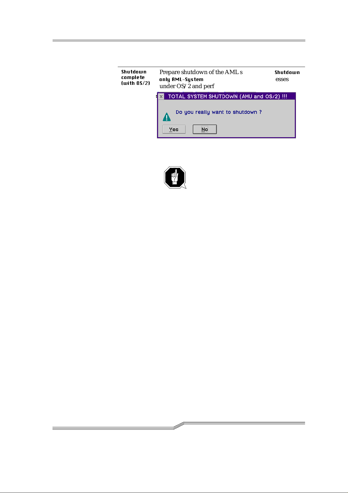
Command Field Explanation
6KXWGRZQ
FRPSOHWH
ZLWK26
Prepare shutdown of the AML sy stem (as in
RQO\$0/6\VWHP
) and then break off all processes
6KXWGRZQ
under OS/2 and p e rf orm OS/2 syst e m shutdown.
Fig. 5-6: "TOTAL SYSTEM SHUTDOWN" window
ATTENTION!
Before shutting down stop the co mmuni-
cation with the host computer (e. g. with
HOLD 1,1).
5-6 Menus an d com m a nd s
DOC D00 025-A
Page 45

5.4 Edit menu
Figure 5-7: "Edit" menu
Command Explana t io n
&XW
&RS\
3DVWH
Cutt in g out the ma rked ob j ect and sa ving it i n th e cli p board (memory of the compute r).
Shortcut: Key combination <Shift>+<Delete>
Copying the marked object into the clipboard.
Shortcut: Key combination <Con trol>+<Ins er t>
Inserting the object from the clipboard at the curr e nt
cursor position.
Shortcut: Key combination <Shift>+<Insert>
March 31 , 1999
5-7
Page 46
5.5 View menu
Figure 5-8: "View" menu
Selecting informati on in differen t disp lay wind ows .
5.5.1 Archive
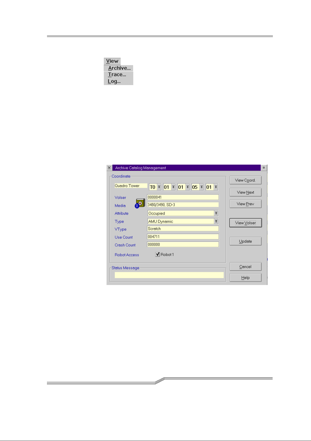
Possibility of controlling and changing archive catalogue entries for the
compartments.
After e n try eithe r of the Vo lser or se l e ct i o n of a coord in a te a l l as so ciated
information from the database is displayed. If a Vol ser is prese nt several
times, only the first entry in the database is displayed.
5-8 Menus an d com m a nd s
Figure 5-9: "Archive Catalog Management" window
DOC D00 025-A
Page 47
.
Field Explanation
&RRUGLQDWH
9ROVHU
Logical coordinates of the mediu m in the archive.
Information
An optical disk occupies 2 logical coordi-
nates, one each for the front and reverse
side.
The individual places of the coordinates have the following contents:
TT
NN S S RR PP
Compartment
Row
Segment
Device No.
Device type
List of all device types (☞ AMU Referen ce Guid e )
Select with the aid of the 4 selection field s the required
coordinate for the display of the data block of a coordinate
Serial number of the medium, represented by a barcode, also called VSN.
The Volser is alphanumeric and 1 to max. 16 charac ters
in length.
Inadmissible Volsers are:
• 0000000000000000
• CLEAN
Enter the Volser in the field to find the medium in the
database.
March 31 , 1999
0HGLXP
Type of the medium for monitoring the archive - drive
assignment
Medium cannot be changed in the Ar chive Catalog
Management.
Information
A distinction is not made basically
between all different types of media
with the same media housing.
List of all media typ e s ( ☞ AMU Reference Guide )
5-9
Page 48

Field Explanation
$WWULEXWH
Status of th e medium (t he charac ters i n brac kets are th e
variables for the database)
2FFXSLHG
(MHFWHG
0RXQWHG
(O) Medium occupies compartment
(E) Compartment empty, medium ejected
(M) Compartment empty, medium in the
drive
,QLWLDO
(I) Not used attribute
,Q-XNHER[
(J)
5HYHUVH6LGH
0RXQWHG
(PSW\
(Y) Compartment empty
8QGHILQHG
(U)
7HPS$ZD\
(T)
Compartment empty,
optical disk i n the ju k e b ox
Compartment empty,
(R)
optical disk in the drive (re verse side)
Not defined (special attribute for
HACC/MVS)
In AML /2 twin rob o t sy s t e m the compartment in the storage tower is occupied temporarily fo r passing through
to the other robot
7\SH
7HPS+HUH
(A)
Occupied compartment in the problem
box
Type o f the comp artm e nt i n the a r c h iv e
6WRUDJH
(S) • Archive co mpart ment for
- hierarchically defined Volser
ranges
- dynamically defined Volser
ranges only in HACC/ MVS
-no Clean
&OHDQ
(N) Cleaning media compartment
$08
'\QDPLF
(A)
(not in HACC/MVS): Archive compartment for dynamic insertion and
passing through
Type o f the comp artm e nt i n the I / O unit
)RUHLJQ
3UREOHP
(F) Foreign media compartment
(P) Compartment in the problem box
(I/O unit)
5-10 Menus an d comma nd s
DOC D00 025-A
Page 49

Field Explanation
97\SH
8VH&RXQW
&UDVK&RXQW
+$&&
'\QDPLF
$08
'\QDPLF
(D)
(A)
Archiv e compa rt me nt f or dyn amic u se
of the I/O unit unde r HA CC /MVS
Archiv e compa rt me nt f or dyn amic u se
of the I/O unit (in HACC/ MVS onl y
for opt i c a l di sk )
Volser type for storage media
•
8QGHILQHG
(U): Undefined (no scratch medium
or scratch media management not on the AMU
•
6FUDWFK
VType cannot be changed in the Ar chive Ca talog Ma nagement.
Number of accesses to the compartment.
Use Count cannot be changed in the Archiv e Ca talog
Management.
not used
(S): Scratch medium
Information
The value of this field can be changed
only with a host command.
5RERW
$FFHVV
6WDWXV
0HVVDJH
Access right of the robot to the compar tme nt
Answer of AMS with message number (☞ AMU Reference Guide)
after an unsuccessful command
(e. g. Not found: RC = 1032)
March 31 , 1999
5-11
Page 50

Commands
Command Explanation
9LHZ
&RRUGLQDWH
9LHZ1H[W
9LHZ3UHY
9LHZ9ROVHU
8SGDWH
Display of the archive catalogue entry for the entered
logical archive coordinate.
Display of the archive catalogue entry of the next coordinate of the component. If the last coordina te is
reached, there is no further paging.
Display of the archive catalogue entry of the previous
coordinate of the component. If the first coordinate is
reached, there is no further paging.
Display of the archive catalogue entry for the entered
Volser.
Information
This com ma nd ca n be e xec ut ed o nly
after logging in as administrator or
supervisor.
Changing the AMU archi ve catalogue for the ar chive
coordinate.
ATTENTION!
5-12 Menus an d comma nd s
The existing entry is only overwritten in
the AMU archive catalogue. If there are
incorrect entries, discrepancies in the
archive and to the HACC/MVS archive
catalogue can arise.
DOC D00 025-A
Page 51

5.5.2 Trace
Online or offline trace of the internal processes of the AMU software
(AMS and DAS). You can select the traced processes according to areas
(proc e sses of th e AM U ) .
Information
Proces sing can be slow e d down by select i n g Trace!
Change the selection only after consultation with ADIC/GRAU Stor-
age Systems (Support) or ADIC.
Standard se l ect io n : no tr ac e s
ATTENTION!
The concurrent trace has only a limited memory. Save the trace as
quickly as possible in the case of error.
March 31 , 1999
Figure 5-1 0 : "Trace" win dow
Field/com-
mand
/LVWRI
7UDFH,'·V
7UDFH
✔
2QOLQH
Select the trace levels with <Space bar> or the mouse.
List of all Trace ID’s (☞ AMU Reference Guide )
The current trace is displa y e d additional ly on the
screen wi th
• Time of day
• Trace-ID (e.g. 03100 means Trace KRN 1)
• Trace entry (depending on trace type)
Explana tio n
5-13
Page 52

Time of day
Trace ID Trace text
Figure 5-11: "Trace" window (Online)
2))
21
6HOHFW$OO
8QVHOHFW$OO
)LOHQDPH
6DYH
/
The trace is switched off.
Writes the current traces in the main memory (1 MB
reserved). If the memory is exhausted, the oldest entry
is written over.
All entries in the online trace window are marked or
the marking is removed
Path and file name of the trace in binary format, after
execution of the
6DYH
command
Saving the traces in a file with the name preset in the
Filename field in binary format
Select this command immedi a tely after occurrence of
the proble m so that the trace inf ormation is not lost.
You can print this file with the OS/2 Print command
only after f ormatting (
☞
)RUPDW
).
5-14 Menus an d comma nd s
DOC D00 025-A
Page 53

)RUPDW
Brings a trace file saved with the
6DYH
command into a
printable form (ASCII).
Figure 5-12: "Format Trace Files" window
: Target file name with path
D?QDPH
(e. g.
F?DPX?ORJ VWUF? QDPH
or
).
starts the formatting.
Execution is confirmed by outputting the "
" text.
IRUPDWWHG
,QILOH
2XWILOH
6WDUW
)RUPDW
WLQJ
RUPDWW
f
WHG
Path and name of the binary trace file for
conversion into ASCII format
(default: C:
?
AMU?LOGS-TRC)
Path and name of the ASCII trace file after
conversion into ASCII format
Execution of formatting
Select this command after you have
entered the f ile names in th e
2XWILOH
field.
,QILOH
and
Status display of format tin g, format tin g is
completed at
.
March 31 , 1999
5-15
Page 54

5.5.3 Log
The Alerter logs all messages (even if the AMU-Log Control Center window is not opened).
Examples:
• Commands of the host computer
• Execu ti o n of the co mman ds
• Messages to the host computer
• User interventions
• Error messages
Log files start daily at 0.00 hours. If the availabl e memor y on the hard
disk drops below a value defined in the ARTCFG.DAT configuration file
(default 40 MB), the oldest log f iles are deleted.
Information
Log files cannot extend over several days!
There is only one log file for each day.
.
5-16 Menus an d comma nd s
Date
Message number
Time
Command sequence
number
Figure 5-13: "AMU Log" window
Message text
DOC D00 025-A
Page 55

Field/command Explanation
/RJDUFKLYH
Opens a window for selec ting the saved log fil e s with
automatic display in the OS/2 editor EPM
The log file name is composed of
lo <YY> <MM><DD>.001
<YY>: Year
<MM>: Month
<DD>: Day
List with all files
saved in the defined
log folder
Status information
(e.g. number of log
files or selection)
Status information
(e.g. path name or
instruction for opening
file)
March 31 , 1999
Figure 5-14: "View Log Files" window
View Copies the selected file into a temporary
file (logview.txt). This file is displayed in
the OS/2 editor EPM and can be edited
further as desired.
5-17
Page 56

)RQWVL]H
Selection of font, size and style for the contents in the
$08/RJ
window
Figure 5-15: "L og Font Dialog" window
1DPH
6L]H
6W\OH
'LVSOD\
3ULQWHU
2XWOLQH
8QGHUOLQH
6WULNHRXW
6DPSOH
2N
Drop-down list box for all installed fonts
Drop-down list box of the size for the
selected font in pt
Drop- down lis t b o x of th e st y le of th e
selected font (available only for certain
fonts)
Selection of the screen fonts, do not
change the setting
not used
Outl i ne d ty p e
Underlined ty p e
Struck through type
Display of an example of the selected font
Activates the selection for the current
AMU log. On renewed opening of the
AMU Log window, the default fon t (system V I O) is us e d again .
5-18 Menus an d comma nd s
DOC D00 025-A
Page 57

5.6 Operations menu
Figure 5-16: "Operations" menu
5.6.1 Operator login
Command Field Explanation
/RJLQ
2SHUDWRU
Logoff
To use the disabled functions in the Operator menu,
you must log i n as operator, admi nistrator or supervisor
For protection against unauthorized use, you should
log off after the application
Figure 5-17: "Operator Login" window
3DVVZRUG
2N
Field for entering the operator password.
You receive this password from your system administrator
Execution of the login process
March 31 , 1999
5-19
Page 58

5.6.2 Manual Operation
Prerequisite: "MANUAL" operating mode
Manual execution of the host commands of
ator.
Step 1 Switch the main switch off
0RXQW
and
(MHFW
by the oper-
Step 2 In the case of
0RXQW
comman ds, mount the ca rtridge in the
stated drive
Step 3 Confirm the execution of the displayed command with
2.
The executed task is acknowl edge d to the host com pute r and this
shows the next command
Step 4 On re s u m p ti o n of the a u to matic mo d e , pe rf o rm an ins e r ti o n
operation for all cartridges used in the manual mode
.
5-20 Menus an d comma nd s
Figure 5-18: "Manual Operation" window
Command/
field
&RPPDQG
Comm and of the host which shou l d be p e rf o rmed by
Explanation
the operator
9ROVHU
Search in
/RFDWLRQ
for the Volser or VSN to execute the
command
DOC D00 025-A
Page 59

Command/
field
Explanation
/RFDWLRQ
'ULYH
2.
Statement of the coordinates in the archive where the
9ROVHU
for the com mand is currentl y l o ca te d
8QLW
6HJP
Number of the storage tower or rack
Number of the segments for the storage
towers
5RZ
Row in the segmen t (count ing fr om bel ow
to above)
3RV
1DPH
Compartment (counting from lef t to right)
Designation (comment) which is allocated
to the compone nt in the configuration
Plac e the me d iu m with the
9ROVHU
in the drive designated in this f ield
With an EJECT command (ejection) the field remains
free
1DPH
Designation (comment) which is allocated
to the drive in the configuration
Actuate after the command has been executed by the
operator.
Database update is performed, host receives positive
response
March 31 , 1999
5HMHFW
Actuate if the command has not been executed by the
operator.
Database update is not performed, host receives negative response
5-21
Page 60

5.6.3 Disaster Recovery
Dialog box for starting the ejection of preselected media in an emergency
(Disaster Recovery). The window is divided into two sections for independ e nt re j e ct i o n of th e media in AM L/ 2 tw i n robot systems .
Figu re 5-1 9 : "D isaste r Re co very" w in d ow
Command/
field
)LOH
6WDUW
6WRS
6WDWXV
Explanation
Drop-down list box for selecting the prepa red files
with Volsers for ejection.
Display of all files in the C:\AMU\RECOVERY\
folder with file name
*.DSR
(☞ AMU Reference Guide)
Startin g the e j e ction of the medi a f rom the selected file
Interruptio n of e jection
Display of th e cu rrent situation on ejecti on
5-22 Menus an d comma nd s
DOC D00 025-A
Page 61
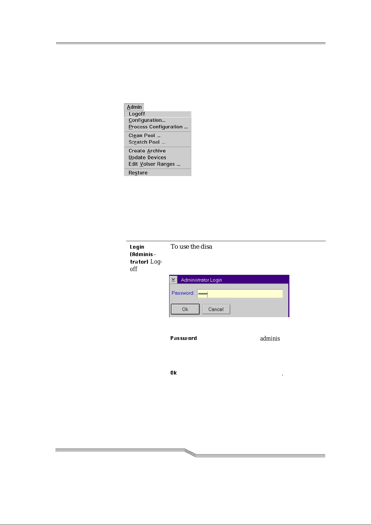
5.7 Admin menu
The fun c tions of th e Admin me n u ite m are des cribed in the AMU Refe r ence Guide.
Figure 5-20: "Admin" menu
5.7.1 Admin istrator Login
Command Field Explanation
/RJLQ
$GPLQLV
WUDWRU
Log-
off
To use the disabled functions in the Admin menu you
must log in as administrator or supervisor
For protection against unauthorized use you should
log off again after the applicati on
Figure 5-21: "Administrator Login" window
3DVVZRUG
Field for entering the admini strator password.
You receive this pas s word from your service
partner, ADIC/GRAU Storage Systems or
ADIC
2N
Execution of the login process.
March 31 , 1999
5-23
Page 62

5.8 Window menu
Figure 5-22: "Window" menu
Comm a nd Explanation
&ORVHDOO
:LQGRZ
(list of all
opened
windows)
Closing all opened windows
Selection of the corresponding window
5-24 Menus an d comma nd s
DOC D00 025-A
Page 63

5.9 Help menu
Figure 5-23: "Help" menu
Command Explana t io n
+HOSIRU
KHOS
Information of the use of the start p age of the help
function s.
March 31 , 1999
Figure 5-24: "Using the Help Facility" window
5-25
Page 64

Command Explanation
([WHQGHG
KHOS
Start page for the AMU online help.
Figure 5-25: "Help for AMU - (AML Management
Unit)" window
5-26 Menus an d comma nd s
DOC D00 025-A
Page 65

Command Explanation
+HOSLQGH[
Help index
$ERXW
Figure 5-26: "Help Index" window
Display of the copyright and of the AMU version No.
Figure 5-27: "About AMU" window
March 31 , 1999
5-27
Page 66

5-28 Menus an d comma nd s
DOC D00 025-A
Page 67

6 Processing media
6.1 Overview
In the normal operating procedure cartridges must be added to the
AML/J or removed from it. Three types of I/O units are available for
inserting or ejecting cartrid ges.
• I/O unit/C
• I/O unit/D (HICAP)
• I/O unit/E
There are different functional ranges in the I/O unit for the different
applications:
• "Problem" range
• "Foreign" range
• "HACC Dynamic" range
• "AMU Dynamic" range
March 31 , 1999
6-1
Page 68

The "Fo reign", "HACC Dyn amic" and "AMU Dynamic" ra nges are
defined in the Logical Ra nge s function in the AMS.
Table 6-1: Ranges in the I/ O unit
Problem Foreign
HACC
Dynamic
AMU
Dynamic
Positio n Fixed range
Configurable range in the magazines
with extra large
compartments
Use Cartridges
which are
mechanically
damaged or
cannot be ide ntified by the sys-
Cartridges
with labels
foreign to the
system (no
or not reada-
ble barcode)
tem, pa rt i al l y
also storage of
used cleaning
media
Identifi-
Not po ss ib l e Not poss ib l e W i th com-
cation
Robot
access
Only storage Transport
from and to
the drive, in
the case of
problems to
the problem
box
Volser Symbolic
Volser com-
mencing
with the
symbol "*"
e.g. "*FR001"
Cartridges
which should
be inserted or
ejected with
HACC/MVS
mands of the
HACC/MVS
host software
Transport
from and to
the archive
6-digit alphanumeric
Volser
Cartridges
which should
be inserted or
ejected with
all applications excep t
for HACC/
MVS
Automatically after
changes
(removal of
the magazine)
Transport
from and to
the archive or
to the drive
Alphanumeric Volser
with one to 1 6
characters
6-2 Proce ssing media
Before using the I/O unit obtain inform ation about the configur atio n of
the ranges in your system:
• AMS Graphical Configuration
• HACPARM in HACC/MVS
DOC D00 025-A
Page 69

6.2 I/O unit/C
I/O unit/C handle
March 31 , 1999
I/O unit/C window
Illuminated pushbutton S85
<I/O unit/C enable>
Figure 6-1: I/O unit/C
Production is not inte rrupted wh en inserting cartridges through the I/ O
unit. Insert the cartridges in the I/O unit as follows:
6-3
Page 70

6.2.1 Inser ting cartridges
New cartridges are inserted in the AML/J through the I/O unit.
Step 1 Press the button on the I/O u nit
The button on the I/O unit lights up green and the I/O unit is
unlocked
Step 2 Open the door of the I/O unit
Step 3 Empty the problem box places if cartridges are there
Step 4 Insert the cartridges in the I/O unit. Pay attention to the correct
position .
• Tape head down
• L a bel to the front
Step 5 C lo se th e d o o r of th e I / O unit
The AML/J locks the I/O unit .
According to configuration, the robot ch ecks the maga zine (barcode or
empty place) on the cartridges.
Step 6 Move the cartridge wi th the aid of the host software i nt o the
archive
(exception: foreign mount cartridges)
The cartridge s are broug ht int o the arch ive.
6-4 Proce ssing media
DOC D00 025-A
Page 71

6.2.2 Ejecting cartridges
Cartridges are ejected from the AML/J through the I/O unit.
Production is not inte rrupted when ejecting c a rtridge s with the I/O unit.
Eject the cartridges as follows with the I/O unit:
Step 1 Perform the ejection command from your application or HOST
software.
The cartridges ar e brou ght into the I/O unit
Step 2 Press the button on the I/O u nit
The button on the I/O unit lights up green and the I/O unit is
unlocked
Step 3 Open the door of the I/O unit
Step 4 Empty the problem box places if cartridges are there
Step 5 Remove the cartridges fr om the I/O unit
Step 6 C lo se th e d o o r of th e I / O unit
The AML/J locks the I/O unit .
According to configuration the robot checks the magazine (barcode or
empty place) on the cartridges.
March 31 , 1999
6-5
Page 72

6.3 I/O unit/D (HICAP)
I/O unit electromagnetic
lock and switch
Operating button
Door lock
I/O unit segment 1
(coordinates of E60x010101)
I/O unit segment 2
(coordinates of E60x020101)
Figure 6-2: I/O unit/D
Producti on is interr upted when inserting car t ridges through the I/O
unit/D. Insert the cartridges in the I/O unit as follows:
6-6 Proce ssing media
DOC D00 025-A
Page 73

6.3.1 Inser ting cartridges
New cartridges are inserted in the AML/J through the I/O unit.
Step 1 Press the button on the I/O u nit
The robot moves into the rest position. The power voltage of the robot
control is switched off. The button on the I/O unit lights up green and
the I/O unit is unlocked.
Step 2 Open the door of the I/O unit
Step 3 Insert the cartridges in the I/O unit. Pay attention to the correct
position .
• Tape head to the right
• L a bel to the front
Step 4 C lo se th e d o o r of th e I / O unit
Step 5 Press the <Control on> button
The power voltage is switched back on. The AML/J locks the I/O unit.
The robot performs a homing run.
According to configuration the robot checks the magazine (barcode or
empty place) on the cartridges.
Step 6 Move the cartridge wi th the aid of the host software i nt o the
archive
(exception: foreign mount cartridges)
The cartridge s are broug ht int o the arch ive.
March 31 , 1999
6-7
Page 74

6.3.2 Ejecting cartridges
Cartridges are ejected from the AML/J through the I/O unit.
Producti on i s not i nte rru pted when ej ec tin g car tr idges wit h the I /O un it .
Eject the cartridges as follows with the I/O unit:
Step 1 Perform the ejection command by your application or HOST
software.
The cartridges ar e brou ght into the I/O unit
Step 2 Press the button on the I/O u nit
The robot moves into the rest position. The power voltage of the robot
control is switched off. The button on the I/O unit lights up green and
the I/O unit is unlocked.
Step 3 Open the door of the I/O unit
Step 4 Remove the cartridges fr om the I/O unit
Step 5 C lo se th e d o o r of th e I / O unit
Step 6 Press the <Control on> button
The power voltage is switched back on. The AML/J locks the I/O unit.
The robot performs a homing run.
According to configuration the robot c hecks the m ag az ine (b arco de or
empty place) on the cartridges.
6-8 Proce ssing media
DOC D00 025-A
Page 75

6.4 I/O unit/E
Figure 6 - 3: Two I/O units/E
6.4.1 Inser ting cartridges
New cartridges are inserted in the AML/J through the I/O unit.
Step 1 Press the button on the I/O u nit
The button lig hts up gr een. On releas e by the robot c ont rol the shutt er
is unlocked.
Step 2 Op e n the shutte r of the I/O unit
Step 3 Pull out the slide of the I / O uni t
Door lock
Requirement button
Shutter
Step 4 Remove the magazine
Step 5 Insert the cartridges in the magazine. Pay attention to the cor -
rect position.
• Tape head to the right
• L a bel to the front
Step 6 Put the magazine back in the I/O unit
Step 7 Push the slide back in
Step 8 Cl o se th e shutte r of the I/O un i t
The AML/J locks th e shutter o f the I/O unit .
According to conf iguration the robot checks t he magazine (barcode or
empty place) on the cartridges.
Step 9 Move the cartridge wi th the aid of the host software i nt o the
archive
(exception: foreign mount cartridges)
The cartridges are brought into the archive.
March 31 , 1999
6-9
Page 76

6.4.2 Ejecting cartridges
Cartridges are ejected from the AML/J through the I/O unit.
Producti on i s not i nte rru pted when ej ec tin g car tr idges wit h the I /O un it .
Eject the cartridges as follows with the I/O unit:
Step 1 Perform the ejection command by your application or HOST
software
The cartridges are brought into the I/O unit
Step 2 Press the button on the I/O u nit.
The button l ights up g reen. On rele ase b y th e ro bot cont rol t he shutt er
is unlocked.
Step 3 Op e n the shutte r of the I/O unit
Step 4 Pull out the slide of the I / O uni t
Step 5 Remove the magazine
Step 6 Remove the cartridges from the magazine
Step 7 Put the magazine back in the I/O unit
Step 8 Push the slide back in
Step 9 Cl o se th e shutte r of the I/O un i t
The AML/J locks th e shutter o f the I/O unit .
According to c onfigurat ion the robot checks the magazine (b arcode or
empty place) on the cartridges.
6-10 Processing media
DOC D00 025-A
Page 77

6.5 Disaster Recovery
The Disaste r Re covery function enab les cartri dg e s to be ejected, corresponding to a previously defined list (file) without host connection. The
function is used after a failure of the host system for preparing the move
into an alternate computer center.
Step 1 Unload all drives
Step 2 Bring these media ba ck into the ho me po sition with the
command
Step 3 Perform a login in the operator menu.
Figure 6-4: "Operator Login" window
Step 4 Select the
Step 5 Enter the password (defined in
'LVDVWHU5HFRYHU\
command in the
3URFHVV&RQILJXUDWLRQ
2SHUDWRU
)
The Disaster Recovery window is opened.
.((3
menu
March 31 , 1999
Figure 6-5: " Di saste r Recover y" window
Step 6 Select the file for ejection
6-11
Page 78

Information
The entire I/O unit is used for disaster recover y
(incl. foreign mount compartments)
Step 7 Start the ejection with
6WDUW
Step 8 Empty al l media fro m all I/O units as requ ested
Step 9 Confirm ejection with
2.
The media are ejected in the order specified in the selected file
Step 10 Empty the I/O unit if the request appears on the workspace
Step 11 Co ntinue ejection with 2.
The command is acknowledged positively af ter eject ion of the last
medium.
6-12 Processing media
DOC D00 025-A
Page 79

Index
A
About . . . . . . . . . . . . . . . . . . . . . . . . . . 5-27
Address
ADIC . . . . . . . . . . . . . . . . . . . . . . . . 1-3
ADIC/GRAU Storage Systems . . . . 1-3
Admin menu . . . . . . . . . . . . . . . . . . . . 5-23
AML Controller User Guide . . . . . . . . . 1-2
AML Management Unit . . . . . . . . . . . . 2-3
AML/J control unit . . . . . . . . . . . . . . . . 2-2
AML/J Maintenance Guide . . . . . . . . . . 1-2
AMU . . . . . . . . . . . . . . . . . . . . . . . . . . . 2-3
Communication . . . . . . . . . . . . . . . . 2-4
Copyright/Version . . . . . . . . . . . . . 5-27
Hardware . . . . . . . . . . . . . . . . . . . . . 2-4
Help . . . . . . . . . . . . . . . . . . . . . . . . 5-25
Software . . . . . . . . . . . . . . . . . . . . . 2-4
Tasks . . . . . . . . . . . . . . . . . . . . . . . . 2-4
User interface . . . . . . . . . . . . . . . . . 2-4
Workspace . . . . . . . . . . . . . . . . . . . . 5-1
AMU Installation Guide . . . . . . . . . . . . 1-2
AMU Log . . . . . . . . . . . . . . . . . . . . . . 5-16
AMU Problem Determination Guide . . . 1-2
AMU Reference Guide . . . . . . . . . . . . . 1-2
Attribute . . . . . . . . . . . . . . . . . . . . . . . . 5-10
B
Barcode scanner . . . . . . . . . . . . . . . . . . . 2-2
C
Cartridge . . . . . . . . . . . . . . . . . . . . . . . . . 2-7
Clean . . . . . . . . . . . . . . . . . . . . . . . . . . . 5-10
Close
all . . . . . . . . . . . . . . . . . . . . . . . . . . 5-24
Command
Select . . . . . . . . . . . . . . . . . . . . . . . . 5-2
Communication . . . . . . . . . . . . . . . . . . . 2-4
Compartment addressing . . . . . . . . . . . . 2-5
Components of the system
Control cabinet . . . . . . . . . . . . . . . . . 2-3
Control cabinet . . . . . . . . . . . . . . . . . . . . 2-3
Control menu . . . . . . . . . . . . . . . . . . . . . 5-2
CONTROL ON . . . . . . . . . . . . . . . . . . . . 4-2
Coordinate . . . . . . . . . . . . . . . . . . . . . . . 5-9
Coordinates . . . . . . . . . . . . . . . . . . . . . . . 2-5
Copy . . . . . . . . . . . . . . . . . . . . . . . . . . . . 5-7
Crash Count . . . . . . . . . . . . . . . . . . . . . 5-11
Cut . . . . . . . . . . . . . . . . . . . . . . . . . . . . . 5-7
Page 80

D
G
Data
Electrical system . . . . . . . . . . . . . . . 2-9
Description of function . . . . . . . . . . . . . 2-2
Disaster Recovery . . . . . . . . . . . . . . . . 6-11
Drive . . . . . . . . . . . . . . . . . . . . . . . . . . . 2-2
Drives . . . . . . . . . . . . . . . . . . . . . . . . . . . 2-6
Dynamic
AMU . . . . . . . . . . . . . . . . . . 5-10, 5-11
HACC/MVS . . . . . . . . . . . . . . . . . 5-11
E
Edit
Menu . . . . . . . . . . . . . . . . . . . . . . . . 5-7
Ejected . . . . . . . . . . . . . . . . . . . . . . . . . 5-10
Ejecting cartridges . . . . . . . 6-5, 6-8, 6-10
Electrical data . . . . . . . . . . . . . . . . . . . . 2-9
Electrical fuses . . . . . . . . . . . . . . . . . . . . 2-9
Emergency shutdown . . . . . . . . . . . . . . . 4-5
Empty . . . . . . . . . . . . . . . . . . . . . . . . . . 5-10
F
Fault . . . . . . . . . . . . . . . . . . . . . . . . . . . . 5-1
Gripper . . . . . . . . . . . . . . . . . . . . . . . . . . 2-2
Guide
Further information . . . . . . . . . . . . . 1-2
Layout . . . . . . . . . . . . . . . . . . . . . . . 1-1
H
Help menu . . . . . . . . . . . . . . . . . . . . . . . 5-25
HICAP . . . . . . . . . . . . . . . . . . . . . . . . . . 6-6
Homing run . . . . . . . . . . . . . . . . . . . . . . . 4-3
Host connection . . . . . . . . . . . . . . . . . . . 2-1
I
I/O unit . . . . . . . . . . . . . . . . . . . . . 2-6, 2-7
I/O unit/C . . . . . . . . . . . . . . . . . . . . . . . . 6-3
I/O unit/D (HICAP) . . . . . . . . . . . . . . . . 6-6
I/O unit/E . . . . . . . . . . . . . . . . . . . . . . . . 6-9
Illuminated pushbutton
CONTROL ON . . . . . . . . . . . . . . . . 4-2
In Jukebox . . . . . . . . . . . . . . . . . . . . . . . 5-10
Initial . . . . . . . . . . . . . . . . . . . . . . . . . . . 5-10
Inserting cartridges . . . . . . . . 6-4, 6-7, 6-9
Field
Maximize . . . . . . . . . . . . . . . . . . . . 5-2
Symbol . . . . . . . . . . . . . . . . . . . . . . 5-2
Font size . . . . . . . . . . . . . . . . . . . . . . . . 5-18
Foreign . . . . . . . . . . . . . . . . . . . . . . . . . 5-10
Format (Trace) . . . . . . . . . . . . . . . . . . . 5-15
Functional unit . . . . . . . . . . . . . . . . . . . . 2-2
Fuses . . . . . . . . . . . . . . . . . . . . . . . . . . . 2-9
in-ii Index
K
Keyboard . . . . . . . . . . . . . . . . . . . . . . . . 5-1
L
Layout of the windows . . . . . . . . . . . . . . 5-2
Log . . . . . . . . . . . . . . . . . . . . . . . . . . . . 5-16
Logical coordinates . . . . . . . . . . . . . . . . . 2-5
DOC D00 025-A
Page 81

M
Main switch . . . . . . . . . . . . . . . . . . . . . . 3-5
Manual Operation . . . . . . . . . . . . . . . . 5-20
Mechanical lock . . . . . . . . . . . . . . . . . . . 3-5
Menu
Admin . . . . . . . . . . . . . . . . . . . . . . 5-23
Edit . . . . . . . . . . . . . . . . . . . . . . . . . 5-7
Help . . . . . . . . . . . . . . . . . . . . . . . . 5-25
Operations . . . . . . . . . . . . . . . . . . . 5-19
Overview . . . . . . . . . . . . . . . . . . . . . 5-4
Shutdown (AMU) . . . . . . . . . . . . . . 5-5
View . . . . . . . . . . . . . . . . . . . . . . . . 5-8
Window . . . . . . . . . . . . . . . . . . . . . 5-24
Reverse Side Mounted . . . . . . . . . . . . . 5-10
Robot . . . . . . . . . . . . . . . . . . . . . . . . . . . 2-6
Robot system
Homing run . . . . . . . . . . . . . . . . . . . 4-3
S
Scratch-Status . . . . . . . . . . . . . . . . . . . . 5-11
Select online help . . . . . . . . . . . . . . . . . . 5-2
Selecting a command . . . . . . . . . . . . . . . 5-2
Shortcut . . . . . . . . . . . . . . . . . . . . . . . . . . 5-3
Shutdown AMU . . . . . . . . . . . . . . . . . . . 5-5
Shutdown AMU (completely) . . . . . . . . 5-6
Menu bar . . . . . . . . . . . . . . . . . . . . . . . . 5-2
Mounted . . . . . . . . . . . . . . . . . . . . . . . . 5-10
Mouse . . . . . . . . . . . . . . . . . . . . . . . . . . 5-1
N
Normal stopping . . . . . . . . . . . . . . . . . . 4-4
O
Occupied . . . . . . . . . . . . . . . . . . . . . . . 5-10
Operations menu . . . . . . . . . . . . . . . . . 5-19
P
Paste . . . . . . . . . . . . . . . . . . . . . . . . . . . . 5-7
Problem . . . . . . . . . . . . . . . . . . . . . . . . 5-10
Protective devices
Main switch . . . . . . . . . . . . . . . . . . . 3-5
Mechanical lock . . . . . . . . . . . . . . . 3-5
Shutdown menu . . . . . . . . . . . . . . . . . . . 5-5
Starting the AML/J . . . . . . . . . . . . . . . . . 4-3
Stopping the AML/J . . . . . . . . . . . . . . . . 4-4
Emergency shutdown . . . . . . . . . . . . 4-5
Normal stoppping . . . . . . . . . . . . . . . 4-4
Storage . . . . . . . . . . . . . . . . . . . . . . . . . 5-10
Storage cells . . . . . . . . . . . . . 2-2, 2-5, 2-6
Switching off with Shutdown AMU . . . . 5-5
Switching off with Shutdown AMU (complete-
ly) . . . . . . . . . . . . . . . . . . . . . . . . . . . . . 5-6
Symbols
Warning indications . . . . . . . . . . . . . 3-3
Symbols and notes . . . . . . . . . . . . . . . . . 1-2
System data
Electrical system . . . . . . . . . . . . . . . 2-9
System description . . . . . . . . . . . . . . . . . 2-1
T
Target group . . . . . . . . . . . . . . . . . . . . . . 1-1
R
Restarting the AML/J . . . . . . . . . . . . . . 4-6
March 31, 1999
Technical support . . . . . . . . . . . . . . . . . . 1-3
Temp
Away . . . . . . . . . . . . . . . . . . . . . . . 5-10
Here . . . . . . . . . . . . . . . . . . . . . . . . 5-10
iii
Page 82

Title bar . . . . . . . . . . . . . . . . . . . . . . . . . 5-2
U
Undefined . . . . . . . . . . . . . . . . . . . . . . 5-10
Update
Coordinate . . . . . . . . . . . . . . . . . . . 5-12
Use as intended
AML/J-System . . . . . . . . . . . . . . . . 3-2
Use Count . . . . . . . . . . . . . . . . . . . . . . 5-11
V
View
Coordinate . . . . . . . . . . . . . . . . . . . 5-12
Menu . . . . . . . . . . . . . . . . . . . . . . . . 5-8
Volser . . . . . . . . . . . . . . . . . . . . . . 5-12
Volser . . . . . . . . . . . . . . . . . . . . . . . 2-2, 2-7
Volume Serial Number . . . . . . . . . 2-2, 2-7
VType . . . . . . . . . . . . . . . . . . . . . . . . . 5-11
W
Warning indications . . . . . . . . . . . . . . . . 3-3
Window
Corner . . . . . . . . . . . . . . . . . . . . . . . 5-2
Frame . . . . . . . . . . . . . . . . . . . . . . . 5-2
Window menu . . . . . . . . . . . . . . . . . . . 5-24
Windows
Change size . . . . . . . . . . . . . . . . . . . 5-3
Close . . . . . . . . . . . . . . . . . . . . . . . . 5-3
Layout . . . . . . . . . . . . . . . . . . . . . . . 5-2
Move . . . . . . . . . . . . . . . . . . . . . . . . 5-3
in-iv Index
DOC D00 025-A
 Loading...