

Page 1

Installation
and
Operating Guide
Scalar Series
Advanced Digital Information Corporation
Page 2

Copyright Notice
© Copyright adic 1995
The information contained in this document is subject to change without notice.
This document contains proprietary information which is protected by copyright. All rights are reserved. No part
of this document may be photocopied, reproduced, or translated to another language without the prior written
consent of adic.
adic shall not be liable for errors contained herein or for incidental or consequential damages (including lost
profits) in connection with the furnishing, performance or use of this material whether based on warranty, contract,
or other legal theory.
Printed in the USA
December 1996
Document Number 62-0099-01 Rev C
Advanced Digital Information Corporation
Telephone: (206) 881-8004
Fax: (206) 881-2296
Customer Assistance: (206) 883-HELP
World-Wide Web: http://www.adic.com
BBS: (206) 883-3211
Shipping Address: 10201 Willows Road NE
Redmond, WA 98052
Mailing Address: PO Box 97057
Redmond, WA 98073-9757
adic Europe
Z.A. du Bel-Air
21 avenue Saint-Fiacre
78100 - Saint-Germain en Laye, FRANCE.
33.1.3087.5300
Fax: 33.1.3087.5301
Exabyte® is a registered trademark and EXB-480™ is a trademark of Exabyte Corporation. Quantum® is a
registered trademark of Quantum Corporation.
ii
Page 3

Copyright Notice (Europe)
© Copyright 1995 adic Europe
All rights reserved. No part of this document may be copied or reproduced in any form or by any means, without
prior written permission of adic Europe, Z.A. du Bel-Air, 21 avenue Saint-Fiacre, 78100 - Saint-Germain en
Laye, FRANCE.
adic Europe assumes no responsibility for any errors that may appear in this document, and retains the right to
make changes to these specifications and descriptions at any time, without notice.
This publication may describe designs for which patents are pending, or have been granted. By publishing this
information, adic Europe conveys no license under any patent or any other right.
adic Europe makes no representation or warranty with respect to the contents of this document and specifically
disclaims any implied warranties of merchantability or fitness for any particular purpose. Further, adic Europe
reserves the right to revise or change this publication without obligation on the part of adic Europe to notify any
person or organization of such revision of change.
Every effort has been made to acknowledge trademarks and their owners. Trademarked names are used solely for
identification or exemplary purposes, any omissions are made unintentionally.
adic Europe is a trademark of adic.
iii
Page 4

EMI/RFI Compliance
United States – FCC
WARNING: This equipment has been tested and found to comply with the limits for a Class B digital device,
pursuant to Part 15 of the FCC Rules. These limits are designed to provide reasonable protection against harmful
interference in a residential installation. This equipment generates, uses, and can radiate radio frequency energy
and, if not installed and used in accordance with the instructions, may cause harmful interference to radio
communications. However, there is no guarantee that interference will not occur in a particular installation. If this
equipment does cause harmful interference to radio or television reception (which can be determined by turning
the equipment off and on) the user is encouraged to try to correct the interference by one or more of the following
measures:
• Re-orient or relocate the receiving antenna.
• Increase the separation between the equipment and receiver.
• Connect the equipment into an outlet on a circuit different from that to which the receiver is connected.
• Consult the dealer or an experienced radio/TV technician for help.
You may find the following booklet prepared by the Federal Communications Commission helpful: How to
Identify and Resolve Radio-TV Interference Problems. This booklet is available from the US Government Printing
Office, Washington, DC 20402, Stock No. 004-000-00354-04.
Any changes or modifications not expressly approved by adic could void the user's authority to operate this
equipment.
Canada – Department of Communications
This digital apparatus does not exceed the Class B limits for radio noise emissions from digital apparatus as set out
in the interference-causing equipment standard entitled "Digital Apparatus", ICES-003 of the Department of
Communications.
Cet appareil numérique respecte les limites de bruits radioélectriques applicables aux appareils numériques de
Class B prescriptes dans la norme sur le matériel brouilleur: "Appareils Numériques", NMB-003 édictée par le
ministre des Communications.
Shielded Cables
Shielded data cable(s) are required in order to meet EMI/RFI limit specifications. The adic data cable meets this
requirement. If you need a replacement cable, be sure to use an adic-approved shielded cable (to assure
acceptability to EMI/RFI requirements).
iv
Page 5

DECLARATION OF CONFORMITY
according to EN 45014
Manufacturer’s Name:
Manufacturer’s Address:
declares, that the product:
Product
(Produit, Erzeugnis):
Model Number
(Marque Commercial,
Warenbezeichnung):
conforms to the following international specifications, as required by 89/336/EEC & 92/31/EEC:
EMI:
EMC:
Safety:
Supplementary Information:
10201 Willows Road 21-23 Av. Saint-Fiacre
Redmond, Washington 98052 F-78100 Saint-Germain-en-Laye
USA France
SCALAR 448
SCALAR 448
.
EN 50081-1, EN-55022 Class B
EN 50082-1, IEC 801-2, IEC 801-3, IEC 801-4
EN 60950
Advanced Digital Information Corporation
Redmond, Washington USA 18 December 1995
Location Date Signature/Title
63-1095-01 rev A
Product Engineering Mgr.
v
Page 6

Blank Page
vi
Page 7

Table of Contents
Copyright Notice...............................................................................................................................................................ii
Copyright Notice (Europe)...............................................................................................................................................iii
EMI/RFI Compliance.......................................................................................................................................................iv
Safety Warnings............................................................................................................................................................... ix
Precautions........................................................................................................................................................................x
Chapter 1: The Scalar Series....................................................................................................................................................1
Features.............................................................................................................................................................................3
Options.......................................................................................................................................................................4
DLT Drives.........................................................................................................................................................4
Differential SCSI ................................................................................................................................................4
Chapter 2: Getting Started.......................................................................................................................................................7
Requirements.....................................................................................................................................................................8
Unpacking and Inspecting..........................................................................................................................................8
Checking the Accessories...........................................................................................................................................8
Preparing the Library for Installation................................................................................................................................9
Prepare and Install the Data Cartridges......................................................................................................................9
Barcode Labels ...................................................................................................................................................9
Write-Protect Switch...........................................................................................................................................9
Install Data Cartridges ......................................................................................................................................10
Install Cleaning Cartridge (Optional)................................................................................................................10
Close and Lock the Front Door.........................................................................................................................10
Setting the SCSI IDs .......................................................................................................................................................11
Preparing the Host Computer System .............................................................................................................................12
Power Off the Computer..........................................................................................................................................12
Confirm and/or Install the SCSI Host Interface .......................................................................................................12
Backup Software......................................................................................................................................................12
Chapter 3: Connecting the Scalar Library.............................................................................................................................13
Installing SCSI Cables, Jumpers, and Terminators.........................................................................................................14
Determining Your SCSI Configuration....................................................................................................................14
Powering on the System..................................................................................................................................................18
Installing the Backup Software .......................................................................................................................................18
Chapter 4: Equipment Description........................................................................................................................................19
Front Panel Switches and Indicators ...............................................................................................................................20
Rear Panel Switches and Connectors..............................................................................................................................22
Media Interchange Shelf (Mailbox)................................................................................................................................23
Off-Line Mode Menus ....................................................................................................................................................24
Configuration Menu.................................................................................................................................................25
Buzzer Configuration........................................................................................................................................25
Set SCSI ID.......................................................................................................................................................26
Product Sign-On ...............................................................................................................................................26
Off-Line Time...................................................................................................................................................26
Initialize Map Slots...........................................................................................................................................27
Initialize Scan Barcodes....................................................................................................................................27
Barcode Scanner...............................................................................................................................................26
Diagnostics Menu ....................................................................................................................................................28
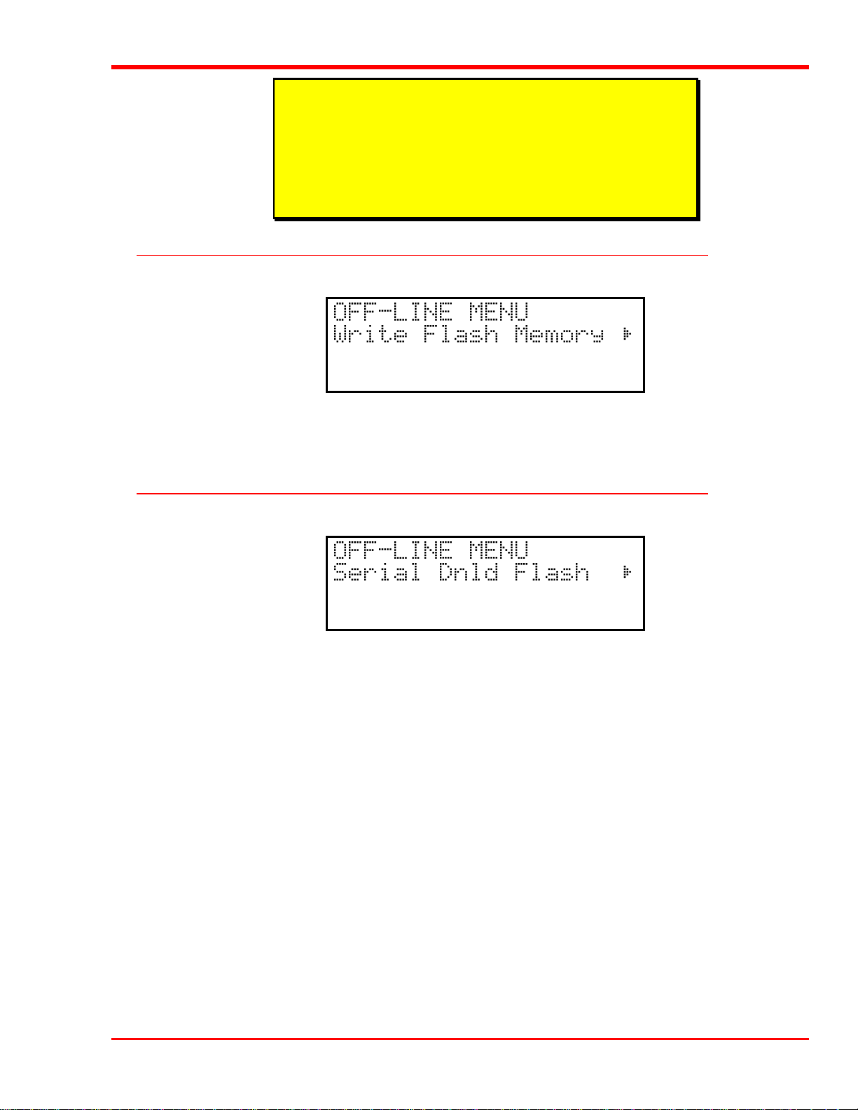
Write Flash Memory Mode......................................................................................................................................29
Serial Dnld Flash Mode ...........................................................................................................................................29
Chapter 5: Operation and Maintenance.................................................................................................................................31
Normal Operations..........................................................................................................................................................32
General Guidelines...................................................................................................................................................32
Power Up Checks.....................................................................................................................................................32
Opening the Front Door...........................................................................................................................................32
vii
Page 8

What Happens When Door is Opened..............................................................................................................33
Resuming Operation.........................................................................................................................................33
Drive Power-on Self-Test ........................................................................................................................................33
Drive Status ......................................................................................................................................................34
Drive Operating Conditions.....................................................................................................................................35
DLT Media..............................................................................................................................................................37
Using the Mailbox (Scalar 458 only).......................................................................................................................38
On-Line Mode ..................................................................................................................................................38
Off-Line Mode.................................................................................................................................................. 39
Manually Loading/Unloading Cartridges to/from the Storage Shelves (Bulk Loading)..........................................41
Normal Maintenance.......................................................................................................................................................42
Cleaning the Drive Head.......................................................................................................................................... 42
Cleaning Tape................................................................................................................................................... 42
Head Cleaning Procedure.................................................................................................................................43
Causes of the Use Cleaning Tape Warning.......................................................................................................44
Cleaning the Enclosure ............................................................................................................................................45
Chapter 6: Troubleshooting and Diagnostics........................................................................................................................47
Installation Problems.......................................................................................................................................................48
Library and Drive Operational Problems.................................................................................................................48
Library Error Codes.................................................................................................................................................49
Environmental Considerations........................................................................................................................................49
When You Call adic Customer Assistance.................................................................................................................... 50
Appendix A: Diagnostics Menu............................................................................................................................................ 51
Appendix B: Glossary........................................................................................................................................................... 61
Appendix C: Specifications................................................................................................................................................... 65
Appendix D: Error Codes......................................................................................................................................................67
Index ......................................................................................................................................................................................71
viii Table of Contents
Page 9

Safety Warnings
CAUTION
RISK OF ELECTRIC SHOCK
DO NOT OPEN
This symbol should alert the
user to the presence of
"dangerous voltage" inside
the product that might cause
harm or electric shock.
CAUTION : TO REDUCE
THE RISK OF ELECTRIC
SHOCK, DO NOT REMOVE
COVER (OR BACK).
NO USER-SERVICEABLE
PARTS INSIDE. REFER
SERVICING TO QUALIFIED
SERVICE PERSONNEL.
Caution
All safety and operating instructions should be read before this product
is operated, and should be retained for future reference. This unit has
been engineered and manufactured to assure your personal safety.
Improper use can result in potential electrical shock or fire hazards. In
order not to defeat the safeguards, observe the following basic rules for
its installation, use and servicing.
1. Heed Warnings - All warnings on the product and in the operating instructions should be adhered to.
2. Follow Instructions - All operating and use instructions should be followed.
3. Ventilation - The product should be situated so that its location or position does not interfere with proper ventilation.
4. Heat - The product should be situated away from heat sources such as radiators, heat registers, furnaces, or other heat
producing appliances.
5. Power Sources - The product should be connected to a power source only of the type directed in the operating
instructions or as marked on the product.
6. Power Cord Protection - The AC line cord should be routed so that it is not likely to be walked on or pinched by items
placed upon or against it, paying particular attention to the cord at the wall receptacle, and the point where the cord
exits from the product.
7. Object and Liquid Entry - Care should be taken to insure that objects do not fall and liquids are not spilled into the
product’s enclosure through openings.
8 Servicing - The user should not attempt to service the product beyond that described in the operating instructions. All
other servicing should be referred to qualified service personnel.
ix
Page 10

Precautions
Do not use oil, solvents, gasoline, paint thinners or insecticides on the unit.
Do not expose the unit to moisture, to temperatures higher than 140ºF (60ºC) or to extreme low temperatures.
Keep the unit away from direct sunlight, strong magnetic fields, excessive dust, humidity and electronic/electrical
equipment which generates electrical noise.
Hold the AC power plug by the head when removing it from the AC source outlet; pulling the cord can damage the
internal wires.
Use the unit on a firm level surface free from vibration, and do not place anything on top of unit.
x
Page 11

The Scalar Series
Chapter
1
This Chapter …
p provides a brief overview of Scalar Library features. For detailed specifications,
see Appendix C.
1
Page 12

elcome to your new adic Scalar Library (Scalar 458 shown above). Your new library is a fully
W
automated, high-performance, high-capacity, mass storage system. The Scalar Series is designed to
provide you with unattended, near-line and off-line data storage, archiving, backup, hierarchical
storage management (HSM), and retrieval for mid-range and high-end servers and networks.
2 The Scalar 448
Page 13

The Scalar Series models (Scalar 224, 448, 458) are SCSI-2 compliant library systems incorporating streaming
tape cartridge data storage devices which feature high capacity, high throughput, and data compression. Equipped
with four Digital Linear Tape (DLT) drives, your library operates as five independent SCSI devices on up to five
SCSI buses. Your library can contain up to 58 data cartridges providing a maximum formatted capacity of 4.06
TeraBytes and a sustained data transfer rate as high as 2400 MB per minute. The tape media is rated at 500,000
passes and has a shelf life of 30 years, providing superior media durability and data reliability.
Scalar Series Models # Drives # Tape Slots Media Interchange Shelf Barcode Reader
Scalar 224 2 24 (std) Optional Standard
Scalar 448 2 - 4 48 (std) Optional Standard
Scalar 458 2 - 4 48 + 10 Standard Standard
Features
l Media Interchange Shelf. When equipped, the Scalar Series 10-slot Media Interchange Shelf (Mailbox),
mounted on the transparent front door, allows you to insert and remove cartridges from your library without
opening the door. Access to each of the five-slot shelves is provided by a separate lockable door. The Mailbox
doors can be locked and unlocked by the application software.
l Multi-function Operator Panel. The Operator Panel, located at the top-left of the front door, employs a 4-
line by 20-character liquid crystal display (LCD) and an eight-key keypad to permit you to monitor and
control the operations of your library.
l Media Picker. The uniquely designed Media Picker is the media cartridge handling mechanism and normally
responds to commands from the application software to move the cartridges between the storage slots, the
drives, and the Mailbox. The Media Picker employs a bi-directional, pass-through gripper which will pick a
cartridge from both the front of the picker, or the back. This design eliminates the need for a separate
cartridge handling mechanism to pick and place cartridges from the Mailbox.
l Barcode Scanner. The Scalar Series Barcode Scanner, mounted on the bottom of the Media Picker, reads
cartridge information contained in a barcode label attached to each of the data cartridges. This information
becomes part of the application software’s library cartridge inventory.
l Exabyte® Emulation. To maximize application software compatibility, your adic library provides
functional emulation of the Exabyte® EXB-480™ library and can appear as either a Scalar or an Exabyte
EXB-480
l System Integrity. The cartridge slots, drives, and robotics are protected by a physically lockable door.
™.
®
System security and media access is controlled by two lockable media interchange shelves. System security
can be enabled or disabled from the application software. Additionally, the Scalar Series Libraries feature a
logical lock system that can be set by the application software. The LOCKED LEDs on the Operator Panel
indicates that the system cannot be interrupted. Functions that would alter the state of the machine cannot be
accessed when the LOCKED LEDs are illuminated.
l Maintainability. The full operation of your library can be viewed through the transparent panel that covers
the front door. If a problem occurs, it is both visible and readily correctable. Any condition that causes a
cartridge load or unload to fail is reported via a message on the Operator Panel LCD.
l Cleaning Cartridge. Although the cleaning cartridge can occupy a cartridge storage slot in the Scalar Library
(facilitating automated cleaning cycles), manual insertion of a cleaning cartridge is permitted through the
Mailbox.
The Scalar 448 3
Page 14

l Manual Cartridge Use. Individual cartridges can easily be transported to the drives through the Mailbox.
l Cartridge Pre-Check. Whenever you power up your Scalar Library the Media Picker will scan the cartridge
storage slots and build a log of valid cartridge locations. Sensors in the Mailbox allow a similar mapping of
the area.
l Reverse Cartridge Protection. The cartridge storage slots, and the slots in the Mailbox employ a design that
prevents the cartridges from being inserted incorrectly.
l Downloadable Firmware. Both your Scalar Library and the DLT drives employ Flash EEPROM technology
permitting easy on-site installation of firmware updates from the host computer.
l Built-in Diagnostics. Your Scalar Library includes diagnostic firmware that tells you when drive head
cleaning is required, reports diagnostic results, and drive operating status. Embedded data logging of
operational embedded and drive errors embedded aid you in failure analysis.
Options
DLT Drives
Your adic library can be equipped with second-, third-, or fourth-generation DLT drives. All drive models
(DLT2000XT, DLT4000, and DLT7000) can read and write 2.6 GB, 6.0 GB, and 10.0 GB tape formats for 100%
interchange compatibility with earlier DLT drives. Tape density is selectable by the application software or a
button on the drive.
Drive Model Cartridge Max Capacity
(compressed mode)
DLT2000XT
DLT4000
DLT7000
20 GB (DLTtape III)
30 GB (DLTtape IIIXT)
20 GB (DLTtape III)
30 GB (DLTtape IIIXT)
40 GB (DLTtape IV)
20 GB (DLTtape III)
30 GB (DLTtape IIIXT)
70 GB (DLTtape IV)
Maximum Capacity and Sustained Transfer Rates
Library Max Capacity
(compressed mode)
480 MB (Scalar 224)
960 MB (Scalar 448/458)
720 MB (Scalar 224)
1.44 TB (Scalar 448/458)
480 MB (Scalar 224)
960 MB (Scalar 448/458)
720 MB (Scalar 224)
1.44 TB (Scalar 448/458)
960 MB (Scalar 224)
1.92 TB (Scalar 448/458)
480 MB (Scalar 224)
960 MB (Scalar 448/458)
720 MB (Scalar 224)
1.44 TB (Scalar 448/458)
3.36 TB (Scalar 448/458)
Sustained Transfer Rate
(compressed mode)
2.5 MB/sec/drive
(150 MB/min/drive)
3.0 MB/sec/drive
(180 MB/min/drive)
10.0 MB/sec/drive
(600 MB/min/drive)
Differential SCSI
Differential SCSI is available for the robotics. The drives can be all differential, all single-ended, or a mix of both.
4 The Scalar 448
Page 15

The Scalar 448 5
Page 16

Blank Page
6 The Scalar 448
Page 17

Getting Started
Chapter
2
This Chapter …
p covers what you need (and what you need to know) to install your adic Scalar
Library. Read this chapter before you begin installation.
7
Page 18

For the most part, installation is simply a matter of checking all necessary SCSI connections installing the
application software (backup or otherwise) on the host computer and applying power. The Scalar Library defaults
set at the factory should be sufficient for most applications.
Requirements
l Space requirements: your Scalar Library has a footprint of 19.0" wide by 23.0" deep. The cabinet extends
40.5" above the floor. You must allow adequate clearance to the rear to allow air flow and enough room at the
front to open the door which extends outward 18.5" when perpendicular to the cabinet. The door is hinged on
the left side. The floor on which the Scalar Library will sit must be level.
l We assume that you are familiar with your computer system. The Scalar Library must be incorporated into the
host computer system. The backup software, SCSI interface and any additional SCSI interface cables must be
purchased separately.
l Necessary tools: No special tools are required to install the Scalar Library. If you are installing a host adapter
(SCSI controller) card at this time, refer to the installation manual for your host adapter.
Unpacking and Inspecting
Caution
If the operating environment differs from the storage environment by
15° C (30° F) or more, let the unit acclimate to the surrounding
environment for at least 12 hours.
Unpack all items from the carton. Save the packing materials in case you need to move or ship the system in the
future.
Caution
You must ship the Scalar Library in the original or equivalent packing
materials or your warranty may be invalidated.
Checking the Accessories
Check to make certain that the following items are included with your Scalar Library:
l Power cord
l One DLT data cartridge
l One DLT cleaning cartridge
l Barcode labels
l One active SCSI bus terminator
l One SCSI Bus Jumper (daisy-chain cable)
l This manual
l Two keys for the front door
8 Getting Started
Page 19

Preparing the Library for Installation
Follow the instructions in Unpacking the Scalar Library adic document number 63-1119-01 to prepare your
library for installation. This document was attached to the front of your library. If you need another copy, please
call adic Customer Assistance.
Prepare and Install the Data Cartridges
Before inserting the cartridges into the library, affix the barcode labels and set the write-protect switches as
described below.
Barcode Labels
To install the barcode labels, position the label with the numbers upright, as shown in figure 3, sliding the label
under the ridges on the sides of the cartridge.
Figure 3. Barcode Labels
Warning
Do not use wrap-around labels on the individual cartridges. Most labels
use a removable adhesive and have a tendency to curl or tear after
multiple uses. This can jam the mechanical movement of the drives and
the Media Picker. Place labels only in the space provided on the
cartridge.
Write-Protect Switch
Make sure that the write-protect switch (figure 4) is set appropriately on each cartridge. Use a ball-point pen or
similar instrument to set the switch.
Getting Started 9
Page 20

ORANGE
INDICAT OR
WRITE-PROTECT
SWITCH
WRITE-PROTECTED
WRITE-ENABLED
Figure 4. DLT Cartridge Write-Protect Switch
Install Data Cartridges
Install each of the cartridges into the library. The cartridge storage slots are designed so that you cannot
incorrectly install the cartridges.
Install Cleaning Cartridge (Optional)
If your backup software is capable of scheduling and performing a drive cleaning cycle automatically, you may
want to dedicate a cartridge storage slot to a cleaning cartridge. When all cleaning cycles on the cleaning cartridge
are exhausted (see Chapter 5: Operations and Maintenance, section Cleaning the Drive Head, for explanation of
how to determine if a new cleaning cartridge is needed), remove the cleaning cartridge and install a new one (if
equipped, use the Mailbox to exchange the cleaning cartridge).
Warning
Use only adic -approved DLT cleaning cartridges. Use of any other
cleaning cartridge may damage the drive heads and void your warranty.
Close and Lock the Front Door
Close the library door, turn the key a quarter turn to the left and remove it from the lock.
10 Getting Started
Page 21

Setting the SCSI IDs
Your Scalar Library consists of up to five SCSI devices; four drives and the library robotics. The library can be
connected to from one to five separate SCSI buses. Each device in your library must be set to a unique ID for the
SCSI bus it is connected to. The ID for the robotics is set by selecting it through the Operator Panel, Off-Line
Mode, Configuration Menu, Set SCSI ID option (see sub-subsection Set SCSI ID, subsection Configuration Menu,
section Off-Line Mode Menus in Chapter 4: Equipment Description of this manual). The IDs for the drives are set
by selecting the appropriate ID on the rotary switch on the back of each drive assembly.
Drive
SCSI ID
Rotary
Switches
Drive
SCSI I/O
Connectors
Library
SCSI I/O
Connectors
Drive SCSI ID Rotary Switches
Getting Started 11
Page 22

Preparing the Host Computer System
Power Off the Computer
p Turn off the power switch.
p Unplug the cord from the AC outlet.
Confirm and/or Install the SCSI Host Interface
Your Scalar Library must be connected to either an integrated SCSI host or a SCSI interface (host adapter) card
installed in the computer – either directly to the I/O connector on the card or as part of an existing SCSI chain. The
SCSI interface must be installed before you connect the library . Refer to the instructions supplied with your
selected SCSI interface.
Backup Software
A variety of backup and data storage software is available for use with your Scalar Library. Please check with
adic Sales or Customer Assistance if you have a question on the compatibility of a particular software package.
Now you are ready to connect the library to your host computer. Follow the instructions provided in the next
chapter.
12 Getting Started
Page 23

Connecting the Scalar Library
Chapter
3
This Chapter …
p provides instructions for physically connecting your Scalar Library to your host
system.
p steps you through the final phase of the installation process.
13
Page 24

Installing SCSI Cables, Jumpers, and Terminators
Follow the steps on the following pages to connect your library to the SCSI bus. This involves installing SCSI
cables, terminators (s) and jumpers (daisy chain cables) onto the SCSI connectors at the rear of the library.
Note
• Make sure that the interface cable(s) you are planning on using
have the appropriate connectors on each end. If the host computer's
SCSI connector is different from that on the your library, you will
need to obtain an adapter or a different cable. Consult your dealer
or adic Customer Assistance if you need help.
• The interface cable(s) must be shielded – adic can supply you with
the correct type(s).
Determining Your SCSI Configuration
The Scalar Library can consist of up to five SCSI devices; four drives and the library. Listed below are the SCSI
configurations supported by the library:
l Connection to up to five SCSI interface channels (buses) are allowed.
l The SCSI buses can be either single-ended or differential. They should each match the peripheral they are
connected to.
l Each tape drive and the library robotics can be connected to separate SCSI buses, or up to four drives and the
robotics can be connected to the same SCSI bus.
l A device (drive or robotics) can be connected to more than one SCSI bus when integrated into a multi-
initiator environment.
l Termination can be active or passive. adic recommends using active termination on a single-ended bus.
l All termination must be external. Never use internal terminators to terminate the drives.
Note
SCSI bus TERM POWER is supplied by the robotics interface, not by
the drives. This can be modified. Please call adic Customer Assistance
if you need to change this.
14 Connecting the Scalar 448
Page 25

The following table provides several examples of SCSI configurations:
Legend
If you have this many SCSI buses... Use this configuration...
1 1
2 2
3 3
4 4
5 5
Install the SCSI cables, terminators, and jumpers as indicated by the configuration illustration.
p Check that the power switches on both your Scalar Library and your host computer are off.
The following symbols are used in the SCSI configuration illustrations:
SCSI Cable to
Host Computer
J
C
T
SCSI
Terminator
J
SCSI Jumper
Configuration Legend
Drive 3 Drive 2 Drive 1Drive 4
J
C
J
J
T
Library Robotics
SCSI Configuration 1 — One SCSI Bus
Connecting the Scalar 448 15
Page 26

Drive 3 Drive 2 Drive 1Drive 4
C
J
C
Library Robotics
C
SCSI Configuration 2 — Two SCSI Buses
C
J
J
T
Drive 3
T
C
Drive 2
C
J
J
T
Drive 1Drive 4
T
C
Library Robotics
SCSI Configuration 3 — Three SCSI Buses
16 Connecting the Scalar 448
T
Page 27
Drive 3 Drive 2 Drive 1Drive 4
T
J
C
Library Robotics
SCSI Configuration 4 — Four SCSI Buses
C
T
C
C
T
Drive 3 Drive 2 Drive 1Drive 4
T T
C
C
T
C
C
T
T
C
T
Library Robotics
SCSI Configuration 5 — Five SCSI Buses
p Attach one end of the SCSI interface cable(s) to the connector(s) shown on the rear of your Scalar Library .
Press firmly and secure the bail locks.
p Plug the other end of the SCSI interface cable(s) into the external connector(s) on the SCSI interface card(s).
Secure the bail locks firmly.
Note
The bail locks at both ends of the SCSI cable must be securely fastened
in order for your library to communicate properly with the computer.
Connecting the Scalar 448 17
Page 28

p Install an external terminator(s) on the appropriate SCSI connector(s) on the rear of your Scalar Library .
Powering on the System
p Plug the power cord into the back of your Scalar Library .
p Plug the power cord from the Scalar Library into a grounded electrical outlet.
Use caution when plugging the power cord into an electrical
outlet. Hazardous voltages are present in the sockets of the
outlet.
p Plug the power cord from your host computer into a grounded electrical outlet.
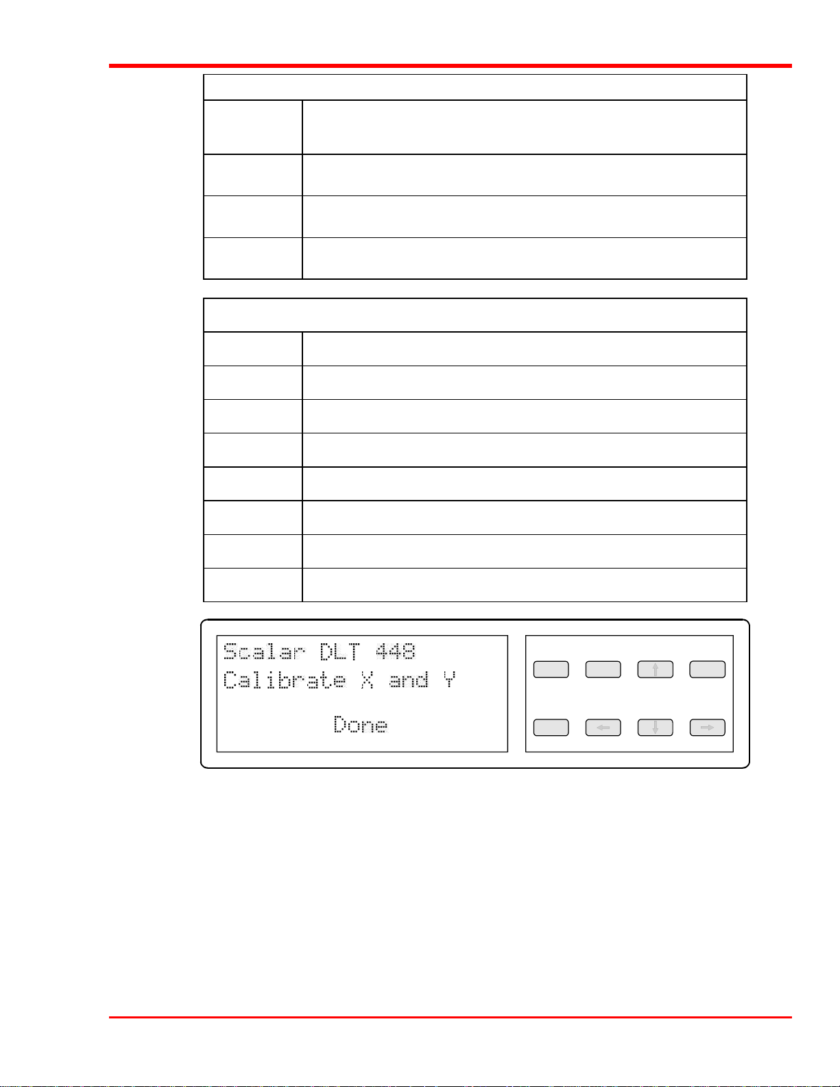
Turn on power to the Scalar Library. Turn on the host computer power. When the library has completed it’s boot
and initialization process it will display a message on the Operator Panel similar to the one shown below:
You are now ready to install the backup software – if it has not already been installed.
Installing the Backup Software
At this point you need to refer to your software installation guide for instructions on installing the
backup/controlling software for the Scalar Library onto the host computer.
This is the software that runs your Scalar Library, not the data being
transferred to the data cartridges. Two examples of backup software are
Cheyenne's ARCserve and Legato's NetWorker.
After you have completed installation of the Scalar Library and of the software, to make sure that your unit is
operating correctly, you should run any diagnostic test(s) supplied with the backup software.
Once your Scalar Library has been connected to your host computer system and the application software has been
installed, the library is ready for use. Just turn on the power switch.
Note
18 Connecting the Scalar 448
Page 29

Equipment Description
Chapter
4
This Chapter …
p describes the switches, indicators and connectors on the front and rear of your
Scalar Library.
p describes the various functions available via the front panel buttons.
p describes the power-up procedure and messages on the front panel LED display.
19
Page 30

Front Panel Switches and Indicators
Switches and indicators on the front panel of the Scalar Library are shown below.
Front of adic Scalar Library (when equipped with Mailbox)
20 Equipment Description
Page 31
Displays and Indicators
Display
Power LED
(green)
LOCKED LED
(upper - green)
LOCKED LED
(lower - green)
MENU
ALT
UP
DOWN
ENTER
The four-line 20-character LCD shows current drive status of the Scalar
Library , allows access to change features or displays error messages.
Lights when the power is on.
Lights when upper row door of Media Interchange Shelf (Mailbox) is locked.
Lights when lower row door of Media Interchange Shelf (Mailbox) is locked.
Keypad Description:
Press this button to enter or exit Off-Line mode menus.
Selects alternate function for another button.
Selects previous item or value in the menu.
Selects next item or value in the menu.
Selects currently displayed item.
ESC
LEFT
RIGHT
Exits current menu and returns to previous menu.
Selects previous field on same line.
Selects next field on same line.
EN TER
Display and Keypad
ALTMEN U UP
DO W N RIGHTLE FT
ES C
Equipment Description 21
Page 32
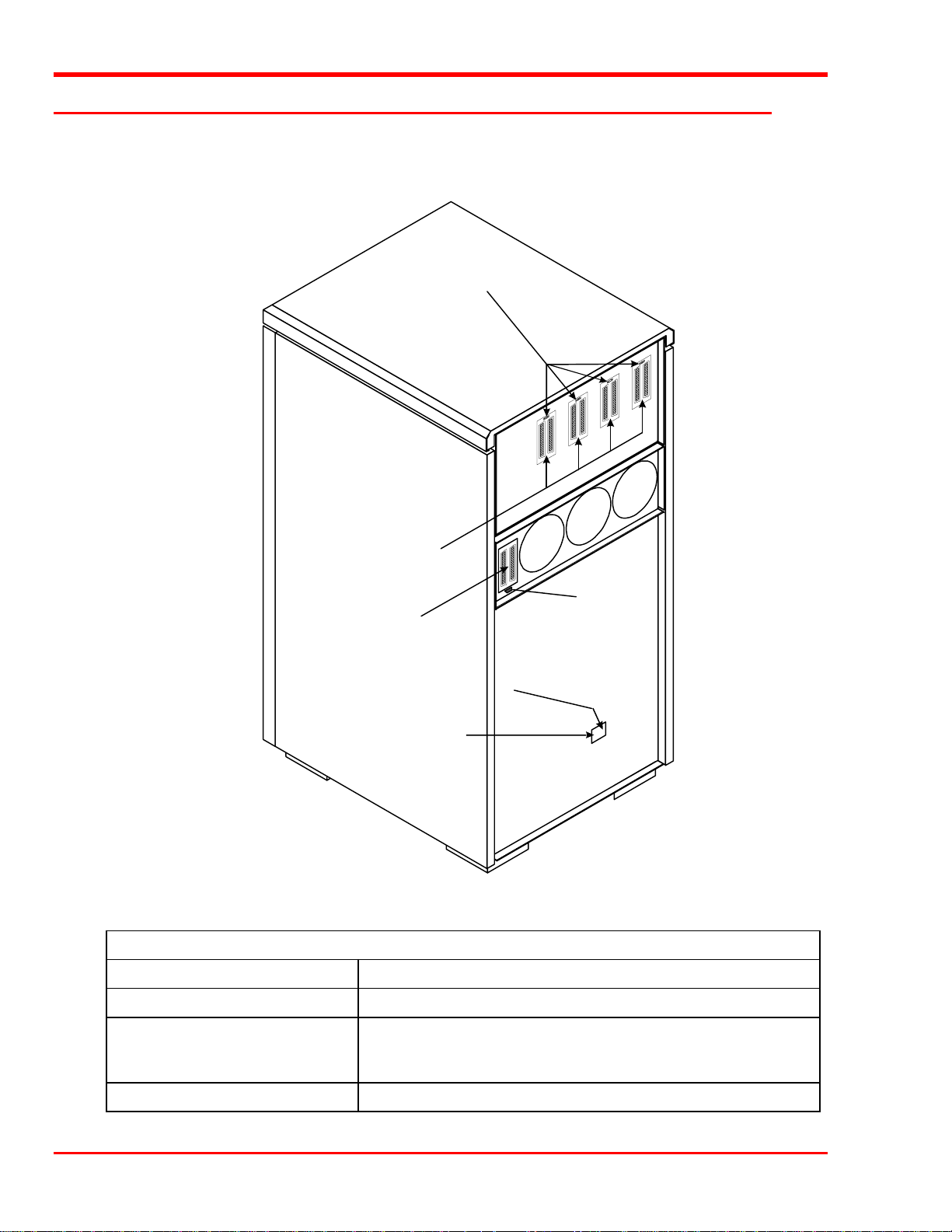
Rear Panel Switches and Connectors
Switches and connectors on the rear of the Scalar Library are shown below.
Drive
SCSI ID
Switches
Drive
SCSI I/O
Connectors
Power Switch
AC Power Connector
SCSI I/O Connectors
Serial Port
Library
Connector
SCSI I/O
Connectors
AC Power
Connector
Power Switch
Rear of adic Scalar 448
Rear Panel Switches and Connectors
Turns on AC power to the Scalar Library.
Plug the Scalar Library AC power cord into this connector.
Connections for the interface cable (s), SCSI jumpers, and/or SCSI
terminators, which are used to connect the Scalar Library to the host
computer SCSI bus(es) or to other devices on the SCSI channel.
Drive SCSI ID Rotary Switches
22 Equipment Description
Sets the SCSI ID for each drive.
Page 33

Media Interchange Shelf (Mailbox)
During normal operation of your Mailbox-equipped Scalar Series Library it is usually not desirable to have to
suspend the activities of your library to insert or remove media cartridges. Both manual and automatic insertion
and removal of media cartridges from your library, without having to open the door, is made possible by the
Mailbox.
The Mailbox consists of a pair of 5-slot cartridge shelves that feature lockable front doors. The library
automatically locks the doors to prevent insertion or removal of cartridges while the robotics is performing pick or
place operations. In the On-Line Mode, access to the Mailbox slots is controllable by your application software.
Use the Mailbox whenever you need to insert, or remove media cartridges from your library. One example would
be to load and unload a cleaning cartridge when cleaning a drive head. Another example would be when it’s time
to migrate your periodic backup to an off-site location. In this example, use the Mailbox to remove the backup
cartridges, and to insert the replacement cartridges.
During the short time it takes you to manually access the media, the
Scalar is off-line to your backup application software.
Note
Equipment Description 23
Page 34
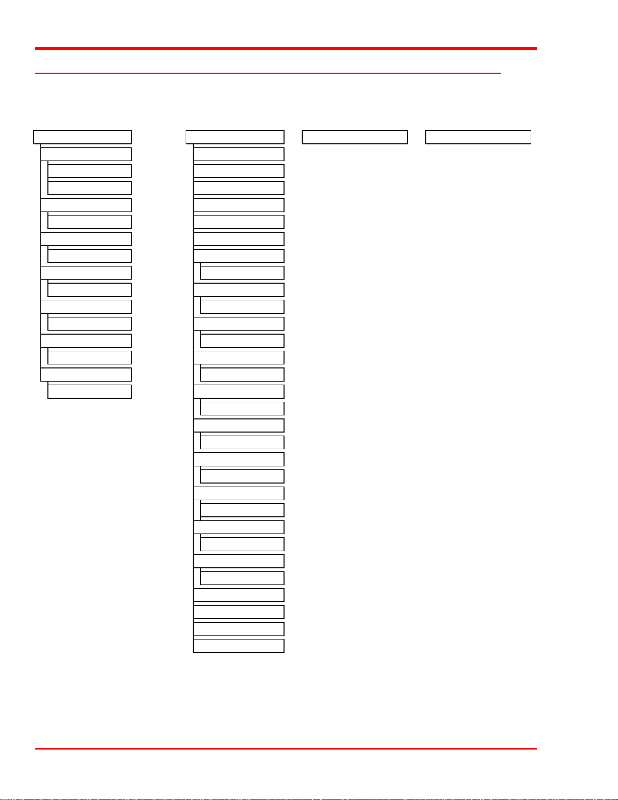
Off-Line Mode Menus
The following diagram is a quick reference to the LCD menus described on the next few pages.
Configuration Menu Diagnostics Menu Write Flash Memory Mode Serial Dnld Flash Mode
Buzzer Configuration Drive Type
ErrAlarm Yes/No Error Counters*
Kybd Yes/No Event Counters*
Set SCSI ID Operation Log*
Library’s SCSI ID: X (0-7) Firmware Revision
Product Sign-On Serial Number*
EXB-480: N Yes/No Pos Picker at Slot
Off-Line Time Row rr, Slot ss (rr = 01-04, ss = 01-12)
Max time 1-99 minutes Pos Picker at Mbox **
Init Map Slots MB Row rr, Slot ss (rr = 01-02, ss = 01--5)
Yes Yes/No Pos Picker at Drv
Init Scan Barcodes Drv Row rr, Drv dd (rr = 01, dd = 01-04)
Yes Yes/No Pick From Slot
Barcode Scanner Row rr, Slot ss (rr = 01-04, ss = 01-12)
Enable Yes/No Pick From Mailbox **
MB Row rr, Slot ss (rr = 01-02, ss = 01--5)
Pick From Drive
Drv Row rr, Drv dd (rr = 01, dd = 01-04)
Place In Slot
Row rr, Slot ss (rr = 01-04, ss = 01-12)
Place In Mailbox **
MB Row rr, Slot ss (rr = 01-02, ss = 01--5)
Place In Drive
Drv Row rr, Drv dd (rr = 01, dd = 01-04)
Map Slots
Scan Bar Codes Yes/No
Calibrate X and Y
Test Secondary Fan
Open Drive Door
Close Drive Door
* not implemented at this time
** If equipped with Mailbox
24 Equipment Description
Page 35
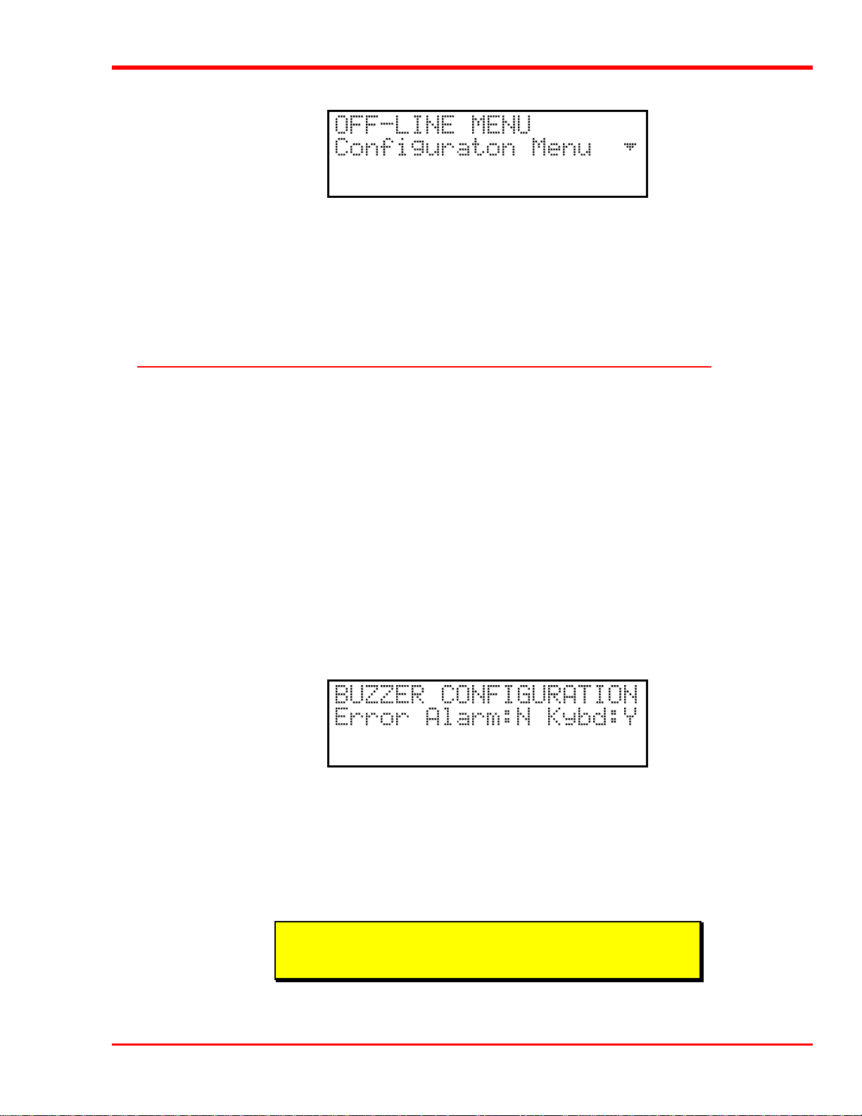
p To access the Off-Line Mode menu, press the MENU key. The display will appear as follows:
p Use the UP or DOWN keys to scroll through the menu choices. Press ENTER to select the item displayed on
the top line. Use the RIGHT or LEFT keys to scroll through fields on the same line.
p To exit the Off-Line Mode menu and return to the On-Line Mode from anywhere in the menu, press the
MENU key.
p Press ENTER to select the Configuration Menu.
Configuration Menu
The Configuration Menu allows you to select the following operating parameters:
l Buzzer Configuration l Set SCSI ID of the Library Robotics
l Product Sign-On l Off-Line Time
l Initialize Map Slots l Initialize Scan Barcodes
l Barcode Scanner
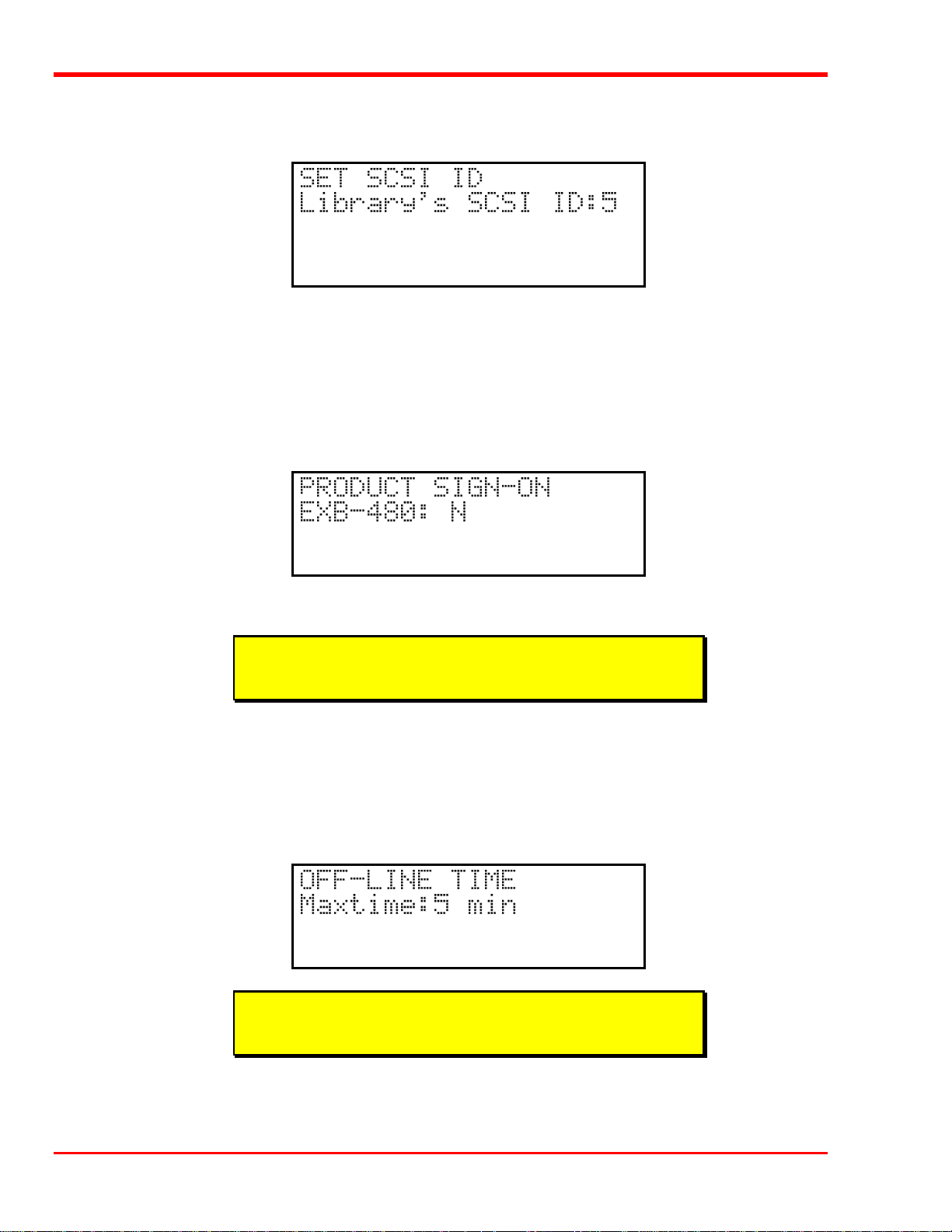
Buzzer Configuration
Enables/disables the sounding of an alarm when an error message or warning alarm is displayed. Enables/disables
the beep sound when you press a keypad key.
When you select the Buzzer Configuration option a display similar to the following appears.
p To enable the error alarm use the LEFT key to select the ErrAlarm field. Use UP or DOWN to select "Y" to
enable alarm or "N" to disable alarm. When the error alarm is enabled, a continuous alarm tone will sound in
the event of an error message. The alarm will sound until the condition that caused the error has been removed
or any key is pressed. To clear an error message from the display, press ALT and ENTER.
p If you wish to change the status of the keyboard beep, use the RIGHT key to select the Kybd field. Use UP or
DOWN to select "Y" to enable a beep when you press a key or "N" to disable the beep.
Note
Buzzer Configuration default: Err Alarm: N, Kybd: Y
p Press ENTER to make the changes effective or press ESC to return to previous menu item.
Equipment Description 25
Page 36
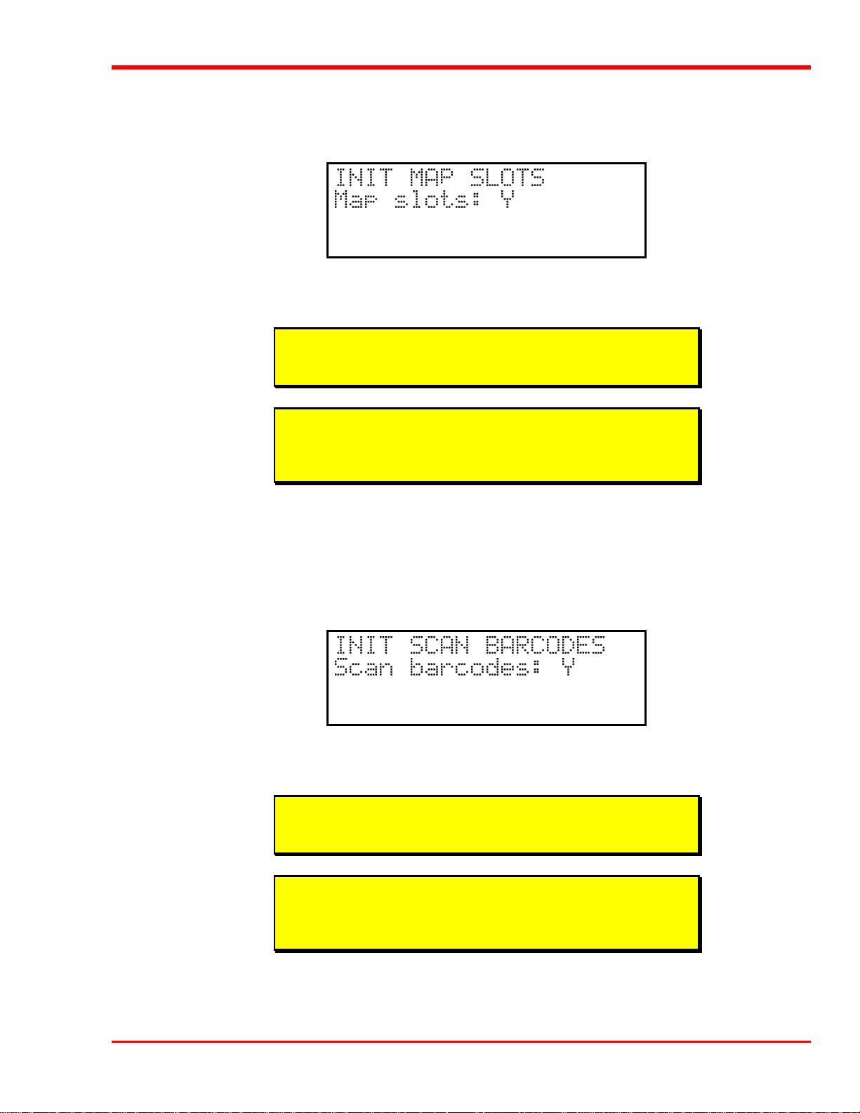
Set SCSI ID
Lets you select the SCSI ID for the robotics on the library.
p Use UP and DOWN to select the desired ID. Press ENTER to execute the change. Confirm the change by
pressing ENTER again.
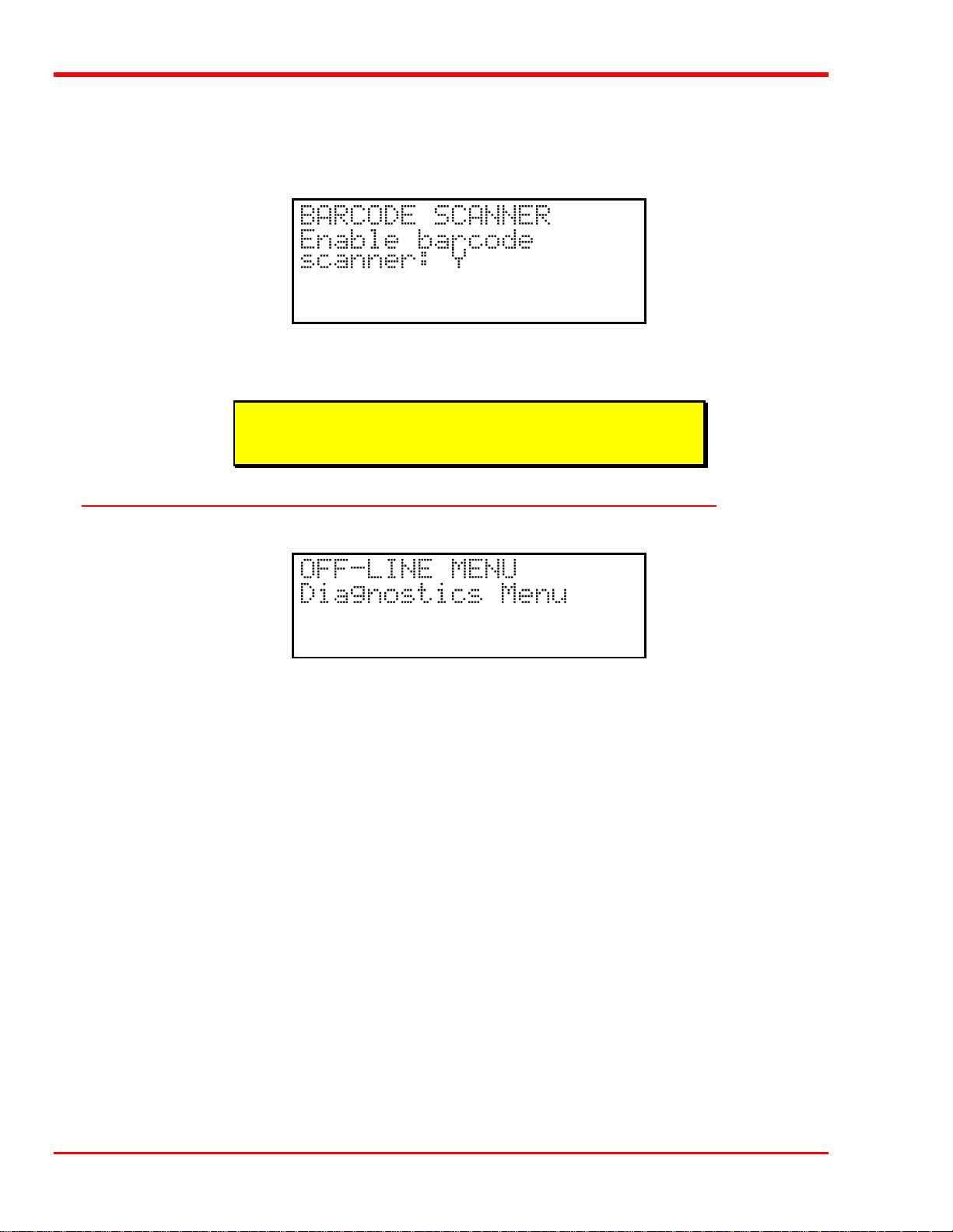
Product Sign-On
Lets you select how the Scalar Library appears to application software. The library can be set to sign-on as an
Exabyte® EXB-480™ library. This permits maximum application software compatibility.
p Use UP or DOWN to select “Y” or “N”. Press ENTER to execute the change.
Note
Product Sign-On default is EXB-480: N.
Off-Line Time
Lets you set the number of minutes the Scalar Library will remain in the Off-Line Mode. If someone leaves the
library in the Off-Line mode, after the pre-set number of minutes the library will automatically return to the OnLine Mode. This assures that your automatic backup will be done even if the library has accidentally been left offline.
Note
Off-Line Time default setting is "5" minutes.
p Use UP or DOWN to select the number of minutes you wish the Scalar Library to remain in Off-Line Mode.
Press ENTER to execute the change.
26 Equipment Description
Page 37
Initialize Map Slots
Enables/disables the mapping of the storage slots whenever the Scalar Library is powered-up, after the front door
has been opened and then closed, or if a SCSI bus Reset occurs
p To disable the mapping of slots use the UP or DOWN keys to select "N". Press ENTER to execute the
change.
Note
Init Map Slots default setting is Y.
Note
Disabling Init Map Slots by selecting “N” will force Init Scan Barcodes
to “N” ( see below).
Initialize Scan Barcodes
Enables/disables the scanning of the cartridge barcodes whenever the Scalar Library is powered-up, or after the
front door has been opened and then closed. The application software overrides the setting of this parameter. If
Barcode Scanner configuration is set to No, Initialize Scan Barcodes is ignored, and the barcode reader is not
available to the application software.
p To disable the scanning of barcodes use the UP or DOWN keys to select "N". Press ENTER to execute the
change.
Note
Init Scan Barcodes default setting is Y.
Note
Enabling Init Scan Barcodes by selecting “Y” will force Init Map Slots
to “Y” ( see above).
Equipment Description 27
Page 38
Barcode Scanner
Enables/disables the barcode scanner. If disabled, the Initialize Scan Barcodes, Configuration Menu parameter
(see above), and the Scan Barcodes sub-function of the Map Slots Diagnostics Menu function (see Appendix A), is
ignored. If disabled, the barcode scanner is not available to the application software.
p To disable the barcode scanner use the UP or DOWN keys to select "N". Press ENTER to execute the
change.
Note
Enable Barcode Scanner default setting is Y.
Diagnostics Menu
The following functions are available under the Diagnostics Menu:
l Drive Type l Error Counters
l Event Counters l Operation Log
l F/W Revision l Position Picker at Slot
l Position Picker at Mailbox (When Mailbox-equipped) l Position Picker at Drv
l Pick From Slot l Pick From Mailbox (When Mailbox-equipped)
l Pick From Drv l Place In Slot
l Place In Mailbox (Scalar 458 only) l Place In Drv
l Map Slots l Calibrate X and Y
l Test Secondary Fan l Open Drive Door
l Close Drive Door
For detailed descriptions of these functions, refer to Appendix A.
28 Equipment Description
Page 39
Note
We strongly recommend that these diagnostic functions be used only by
a qualified service technician. Some diagnostic functions assume the
Scalar Library has been configured correctly and many of the normal
built-in safety checks are turned off. Misusing these diagnostic
functions without the normal safety checks could result in improper
operation (or damage to media and/or the Scalar Library).
Write Flash Memory Mode
The Write Flash Memory Mode is used whenever you upgrade the Scalar Library firmware using the SCSI bus.
When adic releases new firmware for the Scalar Library complete instructions on using Write Flash Memory
Mode and performing the upgrade will be included with the firmware.
Serial Dnld Flash Mode
The Serial Dnld Flash Mode is used whenever you upgrade the Scalar Library firmware using the serial port on the
rear panel. When adic releases new firmware for the Scalar Library complete instructions on using Serial Dnld
Flash Mode and performing the upgrade will be included with the firmware.
Equipment Description 29
Page 40

Blank Page
30 Equipment Description
Page 41

Operation and Maintenance
Chapter
5
This Chapter …
p describes normal operation features of the Scalar Library
p provides details on the media and drive head cleaning cartridge
p explains normal maintenance procedures
31
Page 42

Normal Operations
General Guidelines
Once your Scalar Library and your choice of application software are installed and configured, you can
automatically perform backup and restore operations through the application software. You do not need to
intervene unless you need to replace cartridges through the Mailbox (Scalar 458 only) or by opening the front door
(Scalar 224/448).
Always follow these general operating guidelines:
p Do not open the front door of the Scalar Library unless you absolutely must. Your library cannot operate when
the door is open and always updates the valid cartridge inventory log when the door has been closed again.
Even if you power down your library, you should keep the door closed to protect the internal components
from dust.
p Use only the recommended types of media cartridges, described earlier in this manual.
p Clean each of the DLT drives once a month, or whenever the Use Cleaning Tape LED is illuminated on a
drive front panel (see the subsection titled Cleaning the Drive Head in the Maintenance section later in this
chapter).
Power Up Checks
When you apply power to your library it will perform the following actions:
l Verifies drive configuration and status.
l Builds a valid cartridge inventory log.
l Calibrates the Media Picker and X -Y position of the robotics.
When the library has completed the Power Up Checks it will automatically place itself in On-Line Mode.
Opening the Front Door
Caution
Do not open the front door unless you need to replace data cartridges
(Scalar 224/448), or perform a maintenance operation.
p Insert the key into the lock and turn it to the left.
Warning
Wait until any current application operations are completed. If the door
is opened during a motion, all motion will stop and an error will be sent
to the application.
p Open the front door.
32 Operation and Maintenance
Page 43

What Happens When Door is Opened
Whenever you open the front door of the Scalar Library , the following actions occur:
l The library will return Unit Attention and Not Ready status to the host computer.
l Any function, if executed, that would change the state of the robotics machine is disabled.
Resuming Operation
To resume normal operation, close the door and lock it.
After the door is closed:
l The library will perform its power up checks.
l The application software may update its own cartridge inventory.
Drive Power-on Self-Test
When you power up your Scalar Library , the DLT drives each perform a Power-on Self-Test (POST) while the
library is performing the Power Up Checks. The sequence of events for each drive is:
1. The LEDs on the right front panel of the drive will turn on sequentially from top to bottom. All
LEDs will remain ON for a few seconds.
2. The LEDs on the left front panel of the drive will turn ON at the same time for about three seconds
and then turn OFF.
3. The Operate Handle, Write Protected, and Use Cleaning Tape LEDs will turn OFF. The
Tape in Use LED will blink while the tape drive initializes.
4 If your external SCSI bus terminator has a Term Power LED it should also be illuminated.
Operation and Maintenance 33
Page 44

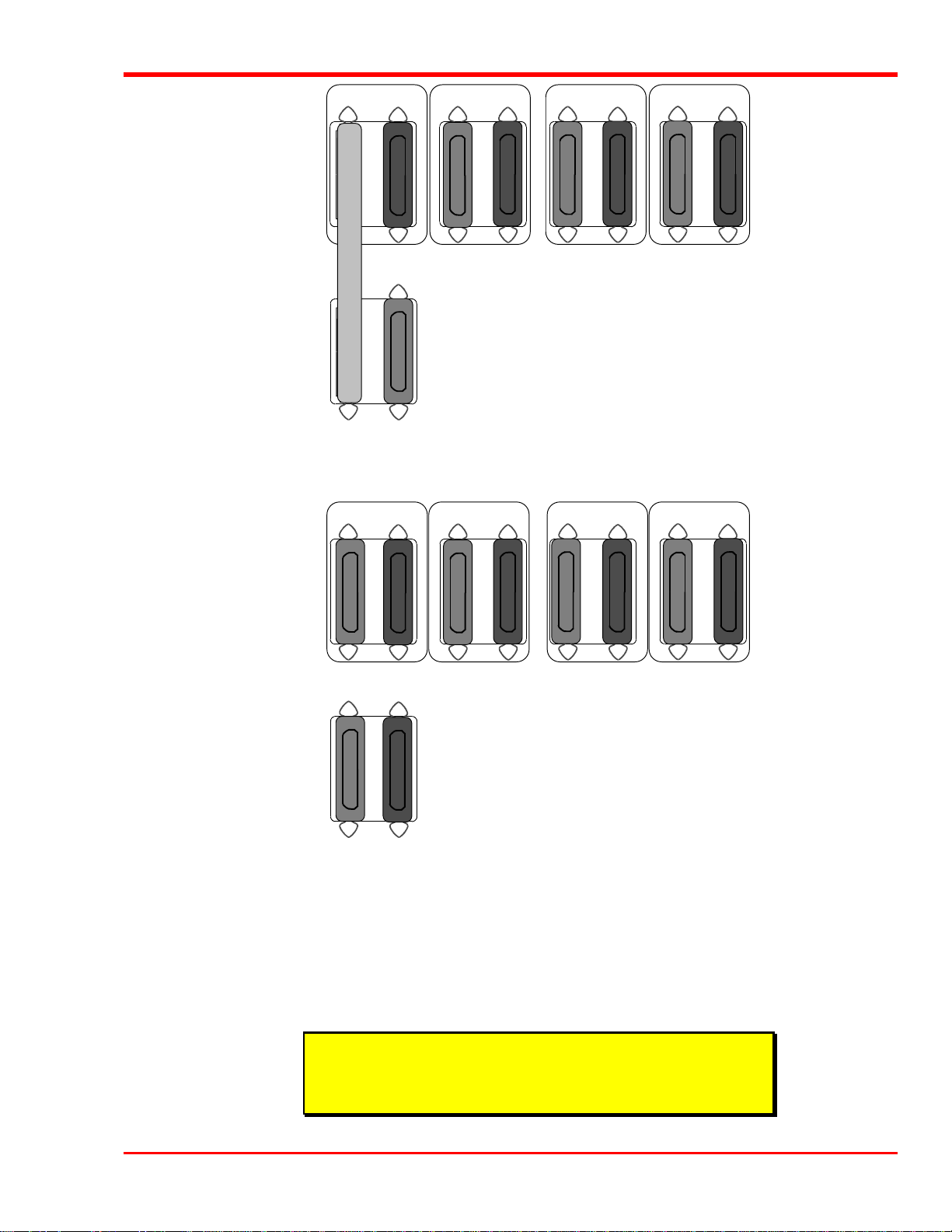
Drive Status
After completion of the drive POST and initialization, each drive will be in one of the four states listed in the
following table:
Drive State Indicator Displays and Actions
1. No cartridge is present
2. A cartridge is present and the handle
is closed.
3. A cartridge is present, but the handle
is open.
4. The drive detects an error condition. Then all right or left side LEDs blink repeatedly. You may try to
A. The Tape in Use LED turns OFF.
B. The Operate Handle LED turns ON.
C. The handle is unlatched.
D. The drive beeps momentarily.
The drive loads the cartridge. When the Tape in Use LED stops
blinking and stays ON, the tape’s actual density lights. For
example, if the actual tape density is 2.6, then the LED turns ON
next to the 2.6 label. When the Density Override LED blinks,
you can select a density. The drive is ready for use.
The Tape in Use LED turns OFF. The Operate Handle LED
flashes. The Scalar Library will close the handle and the drive will
load the cartridge. When the Tape in Use LED stops blinking and
stays ON, the tape’s actual density lights. For example, if the actual
tape density is 2.6, then the LED turns ON next to the 2.6 label.
When the Density Override LED blinks, you can select a density.
The drive is ready for use.
unload the tape and reinitialize the drive by pressing the Unload
key or turn power OFF and then ON again. The right or left side
LEDs stop blinking and the drive tries to reinitialize. The LEDs
turn ON steadily again and then turn OFF if the test succeeds.
The drive POST completes in about 13 seconds on each drive, and the drives will respond normally to all
commands. However, it may take longer for the media to become ready.
34 Operation and Maintenance
Page 45

Drive Operating Conditions
Use the following table to determine each drive’s operating condition:
Label Color State Operating Condition
LED (Right Indicator Panel)
Write Protected
Tape in Use
Use Cleaning Tape
Operate Handle
All Right Indicator
Panel LEDs or,
All Left Indicator
Panel LEDs
Orange ON
OFF
Yellow Blinking
ON
Yellow ON
Remains on after
unloading
cleaning tape
After cleaning,
turns on again
when reloading
data cartridge
Green ON
OFF
ON
Blinking
Tape is write-protected.
Tape is write-enabled.
Tape is moving.
Tape is loaded; ready for use.
Drive head needs cleaning, or the tape is bad.
Cleaning attempted, but tape expired, so cleaning not performed.
Problem data cartridge. Try another cartridge.
OK to operate the Cartridge Insert/Release Handle.
Do not operate the Cartridge Insert/Release Handle.
POST is starting.
An error has occurred.
(continued on next page)
Operation and Maintenance 35
Page 46

Label Color State Operating Condition
LED (Left Indicator Panel)
2.6
6.0
10.0
15.0 (DLT2000XT)
20.0 (DLT4000)
35.0 (DLT7000)
Compress
Yellow ON
Blinking
Yellow ON
Blinking
Yellow ON (default)
Blinking
Yellow ON (default)
Blinking
Yellow ON (default)
Blinking
Yellow ON (default)
Blinking
Yellow ON
OFF
Tape is recorded in 2.6 format.
Tape is recorded in another density. You selected this density for a
write from BOT.
Tape is recorded in 6.0 format.
Tape is recorded in another density. You selected this density for a
write from BOT.
Tape is recorded in 10.0 format.
Tape is recorded in another density. You selected this density for a
write from BOT.
Tape is recorded in 15.0 format.
Tape is recorded in another density. You selected this density for a
write from BOT.
Tape is recorded in 20.0 format.
Tape is recorded in another density. You selected this density for a
write from BOT.
Tape is recorded in 35.0 format.
Tape is recorded in another density. You selected this density for a
write from BOT.
Compression mode enabled. (Compression available only in 10.0, 15.0,
20.0, and 35.0 density.)
Compression mode disabled.
Density Override
All Right Indicator
Panel LEDs, or,
all Left Indicator
Panel LEDs
Yellow ON
OFF (default)
Blinking
Blinking A POST error has occurred.
You selected a density from the front panel.
Density will be selected by the host (automatic).
You are in density selection mode.
36 Operation and Maintenance
Page 47

DLT Media
WRITE-ENABLED
The data cartridges used in the DLT drives are housed in 4-inch plastic cases and employ -inch metal particle
tape.
BAR CODE LABEL
ORANGE
INDICATOR
WRITE-PROTECT
SWITCH
WRITE-PROTECTED
DLT Data Cartridge
The write-protect switch is used to prevent recording over existing data. To prevent recording or deleting, place
the write-protect switch to the open position. The drive senses the position of the switch and will not allow writing
in this position. When installing cartridges in the library or Mailbox, place the switch in the closed position (unless
you do not wish to record on a specific cartridge).
If the switch is moved all the way to the left, the cartridge is write-protected and the drive cannot write to, or erase
data from, the cartridge. The small orange rectangle will be visible whenever the cartridge is write-protected.
Additionally, an arrow (beneath the orange rectangle and above the two lines on the switch), lets you know that
data cannot be written to the cartridge. If the switch is moved all the way to the right, the cartridge is write-enabled
and the drive can write data to, or erase data from, the cartridge. The orange rectangle will not be visible whenever
the cartridge is write-enabled. On the right side of the write-protect switch an arrow over one line indicates that if
you slide the switch to the right, data can be written to the cartridge.
Note
• Store data cartridges in a dry, cool environment.
• Never reset or power down your computer or Scalar Library while
a function is in process or a tape is moving.
Operation and Maintenance 37
Page 48

Using the Mailbox (Scalar 458 only)
On-Line Mode
When the Scalar Library is in On-Line Mode the application software is in control and directs all library
operations. The application software can use the Mailbox to insert or remove individual cartridges to/from the
drives, or to/from the cartridge storage shelves. Follow closely the instructions the application software provides
on your host computer system monitor.
The design of the Mailbox includes access control doors and cartridge stops in each of the media slots. The doors
are unlocked, except when the library is performing a media transport operation (pick and place). The cartridge
stops are solenoid controlled and prevent incorrect insertion of the media. The stops are held in the raised position
whenever the Mailbox access doors are unlocked. During library pick and place operations the stops are lowered,
allowing the library to insert or remove cartridges from the slots using the Media Picker.
Warning
The Mailbox access control doors are locked when the application
software performs a media transport operation (pick and place), or, the
application can lock the access control doors at any time. You cannot
open either door during this operation without severely damaging the
Scalar 458. Wait until your application software instructs you to open
either of these doors.
Loading a Cartridge into Scalar 458 Library
p Open the appropriate Mailbox access control door as instructed.
p Place the cartridge into the appropriate slot of the Mailbox with the write-protect switch at the top and the
barcode label facing you. Slide the cartridge in until the stop will not allow it to go any farther.
Note
The cartridge is inserted with the write-protect switch at the top and the
barcode label facing you. However, the cartridge stops will prevent you
from installing the media incorrectly.
p Close the Mailbox access control door.
p Follow any additional instructions provided by the application software.
The application software will now perform the intended operation with the cartridge.
Unloading a Cartridge from Scalar 458 Library
The application software will cause the cartridge to be ejected from the drive and will issue the pick and place
commands to have the library move the cartridge to a Mailbox slot.
p Open the appropriate access control door and remove the cartridge from the Mailbox.
p Close the access control door.
38 Operation and Maintenance
Page 49
Off-Line Mode
When the Scalar 458 Library is in Off-Line Mode you can use the Mailbox to insert or remove individual
cartridges to/from the drives, or to/from the cartridge storage shelves. If your application software does not
automate the drive head cleaning, use this procedure to manually perform the head cleaning
As in On-Line Mode the access control doors are unlocked, except when the library is picking or placing a
cartridge. The cartridge stops are held in the raised position whenever the Mailbox access doors are unlocked.
During library pick and place operations the stops are lowered, allowing the library to insert or remove cartridges
from the slots using the Media Picker.
Loading a Cartridge into Drive
p Place the Scalar Library in the Off-Line Mode by pressing the MENU key on the Operator Panel.
p Open the Mailbox access control door as instructed.
p Place the cartridge into the appropriate slot of the Mailbox with the write-protect switch at the top and the
barcode label facing you. Slide the cartridge in until the stop will not allow it to go any farther.
p Close the access control door.
p Use the DOWN key to move to the Diagnostic Menu option. Press the ENTER key to select the
Diagnostic Menu.
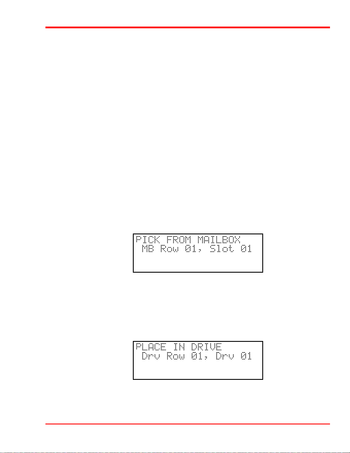
p Use the DOWN key to move to the Pick From Mailbox function. Press the ENTER key.
The display will now show:
p Use the DOWN key to move to the MB Row field. Use the UP or DOWN key to select the Mailbox row
that you placed the cartridge in. Use the RIGHT key to move to the Slot field. Use the UP or DOWN keys to
select the Mailbox slot that you placed the cartridge in. Press ENTER to have the Media Picker pick the
cartridge from the appropriate Mailbox slot.
p Use the DOWN key to move to the Place In Drive function. Press the ENTER key.
The display will now show:
p Use the DOWN key to move to the Drv Row field. Use the UP or DOWN key to select the row the drive is
in. Use the RIGHT key to move to the Drv field. Use the UP or DOWN keys to select the drive you wish to
place the cartridge in. Press ENTER to have the Media Picker place the cartridge into the drive.
Operation and Maintenance 39
Page 50
After you have completed the intended manual operation with this cartridge, follow the procedure outlined in the
next subsection, Unloading a Cartridge from Drive, if you are going to unload the cartridge from the drive and
remove it from the library.
p Return the Scalar 458 Library to the On-Line Mode by pressing the MENU key on the Operator Panel.
Your Scalar 458 Library is once again ready for use.
Unloading a Cartridge from Drive
This description of this procedure assumes that the cartridge you wish to unload from a drive has been loaded into
the drive, since you should not normally have to manually unload a cartridge that has been loaded by application
software. It is further assumed that the cartridge is in the drive, has been logically unloaded by the application
software*, the library is in Off-Line Mode, and you are accessing the Diagnostics Menu.
* If the application software has not logically unloaded the tape, you will need to open the door, reach-in and press
the unload button.
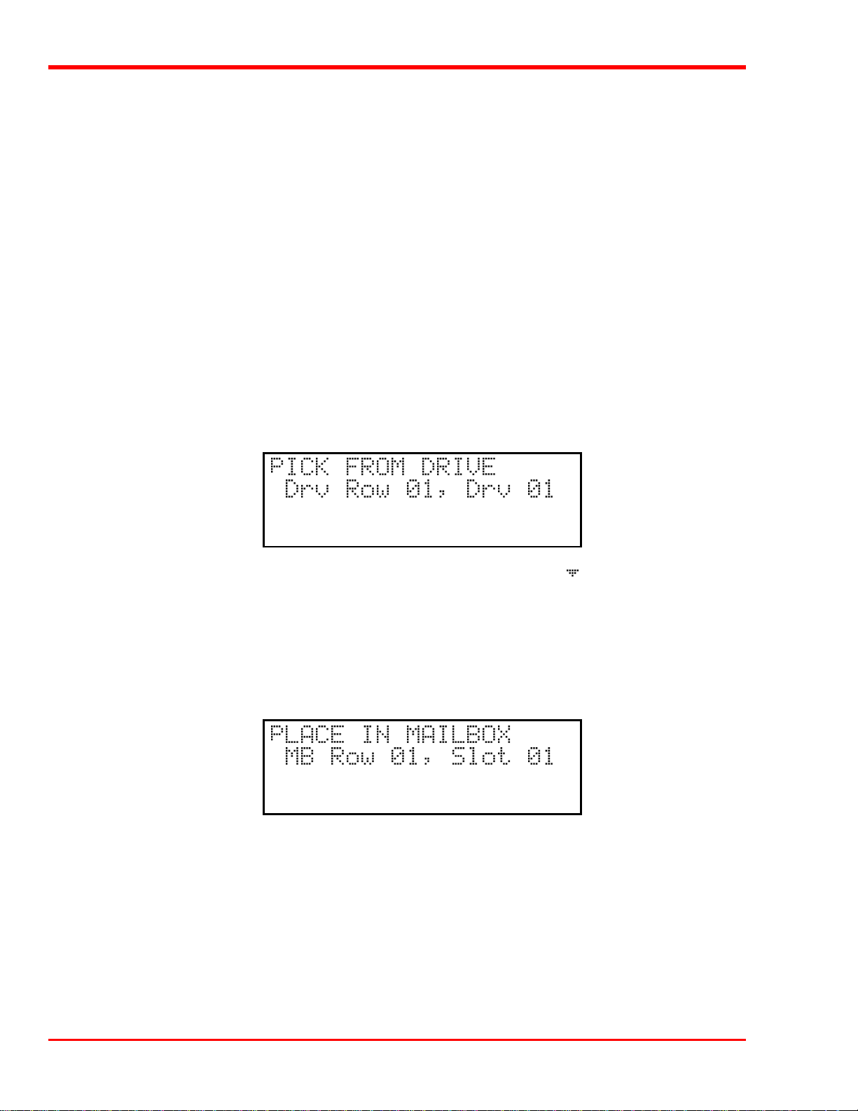
p Use the DOWN key to move to the Pick From Drive function. Press the ENTER key.
The display will now show:
p Use the DOWN key to move to the Drive Row field. Use the UP or DOWN key to select the row the
drive is in. Use the RIGHT key to move to the Drv field. Use the UP or DOWN keys to select the drive.
Press ENTER. The drive will automatically unload the tape and then eject it. When the drive has ejected the
cartridge completely, the Media Picker will pick the cartridge from the drive.
p Use the DOWN key to move to the Place In Mailbox function. Press the ENTER key.
The display will now show:
p Use the DOWN key to move to the MB Row field. Use the UP or DOWN key to select the Mailbox row
that you want to use. Use the RIGHT key to move to the Slot field. Use the UP or DOWN keys to select the
slot you wish to place the cartridge in. Press ENTER to have the Media Picker place the cartridge into the
Mailbox slot.
p After the Media Picker has completed placing the cartridge in the slot, open the appropriate access control
door and remove the cartridge from the Mailbox. Close the access control door.
40 Operation and Maintenance
Page 51

Note
Remember, the access control doors are locked whenever the library is
performing a pick or place operation.
p Return the Scalar 458 Library to On-Line Mode by pressing the MENU key on the Operator Panel.
Your Scalar 458 Library is once again ready for use.
Moving a Cartridge to/from the Storage Shelves
The same functions are performed as loading or unloading a cartridge from a drive to move a cartridge between
the library storage shelves and the Mailbox. The difference is that you use the Pick From Slot, and Place In
Slot functions in addition to the Pick From Mailbox and Place In Mailbox functions in the Diagnostics
Menu.
Manually Loading/Unloading Cartridges to/from the Storage
Shelves (Bulk Loading)
Media can be exchanged on a “bulk” basis by opening the front door and exchanging any or all cartridges in the
shelves (Scalar 458 optional method, see previous section for information on using the Mailbox to exchange
cartridges). The application software will have to re-map the shelves to update it’s cartridge inventory log.
Note
You can manually move the Media Picker assembly right or left to
provide access to the storage shelves. Avoid manually moving the
Media Picker assembly up or down.
Operation and Maintenance 41
Page 52
Normal Maintenance
Cleaning the Drive Head
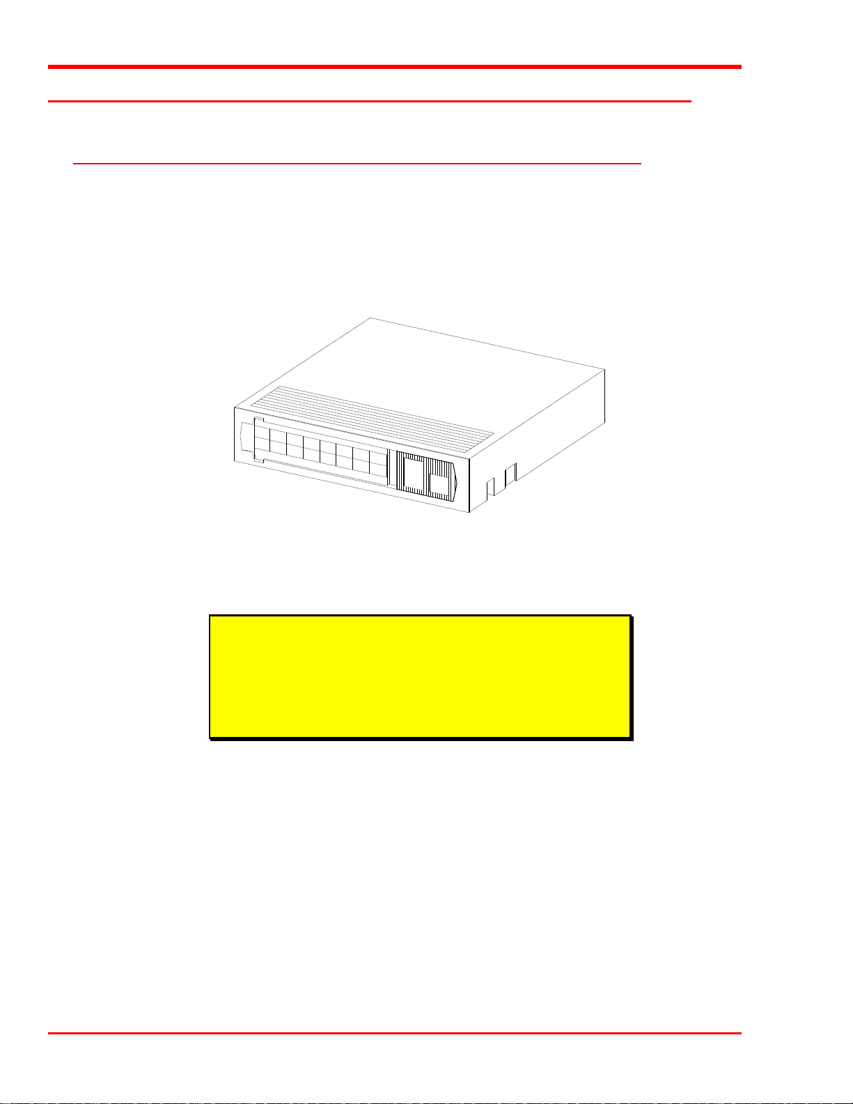
Cleaning Tape
The tape heads should be cleaned once a month, or when the Use Cleaning Tape LED is illuminated on the
drive front panel. Use a DLT cleaning tape to clean the drive heads. A cleaning tape is shipped with your adic
Scalar Library.
Figure 16:. DLT Cleaning Tape
Cleaning the head should always be performed as the first step if the Use Cleaning Tape LED is illuminated on
the drive.
Note
The cleaning cartridge is exhausted after it has performed 20 cleanings.
The cleaning tape includes a label with 20 small boxes printed on it.
Always place a check mark in a box each time the tape performs a
cleaning. Replace the cleaning cartridge when it has performed 20
cleanings (all boxes will be checked).
42 Operation and Maintenance
Page 53

The following table tells you when to use the cleaning tape:
If . . . It means . . . You should . . .
1. The Use Cleaning Tape LED
is illuminated on the drive front
panel
2. A data cartridge causes the Use
Cleaning Tape LED on the
drive front panel to blink
3. The Use Cleaning Tape LED
re-illuminates after performing a
cleaning and reloading the data
cartridge.
The drive head needs cleaning or the
tape is bad
The data cartridge may be damaged Back up the data from this cartridge onto
Cleaning was not accomplished
because the cleaning tape has
exhausted all cleaning cycles.
OR
The data cartridge may be damaged
Use the cleaning tape. Load the cleaning tape
using the procedure in section Using the
Mailbox, subsection Loading a Cartridge
into Drive.
When cleaning is complete, the beeper will
sound alerting you to remove the cleaning
tape. Use the procedure in section Using the
Mailbox, subsection Unloading a Cartridge
from Drive to remove the cleaning tape from
the drive. Log the cleaning onto the label.
another cartridge, it may be damaged. A
damaged cartridge may cause unnecessary
use of the cleaning cartridge.
Replace the cleaning cartridge.
Back up the data from this cartridge onto
another cartridge, it may be damaged. A
damaged cartridge may cause unnecessary
use of the cleaning cartridge.
Note
Keeping a drive clean is the single most important requirement for
achieving and maintaining superior performance.
Head Cleaning Procedure
Cleaning Tape in Mailbox (Scalar 458 only) or Storage Slot
If your application software cannot, or is not configured to automate the cleaning cycle, use the Off-Line Mode,
Diagnostics Menu pick and place functions to move the cleaning cartridge into and out of the appropriate drive.
Caution
Cleaning cartridges are considerably more abrasive to the drive's
recording head than standard data cartridges. Usage should be kept
within the recommended limits.
When you have completed the cleaning procedure be sure to return the Scalar Library to the On-Line Mode by
pressing the MENU key on the Operator Panel.
Manually Inserting the Cleaning Tape
If desired, you can manually insert and remove the cleaning tape into/from the drive. To do this you must open the
front door to the Scalar Library. Review the section titled Opening the Front Door on page 30 before proceeding.
Operation and Maintenance 43
Page 54

To initiate the cleaning cycle manually you must be aware of the
present state of the Scalar Library and the drive that you wish to clean.
If a cartridge is present in the drive, you must first press the UNLOAD
button on the drive front panel, then, when the OPERATE HANDLE
LED is illuminated, open the drive door and remove the cartridge. You
can then proceed with these instructions.
If the drive is empty, but the door is closed, make sure that the
OPERATE HANDLE LED is illuminated before opening the door.
You may then proceed with these instructions.
If the drive is empty, and the door is open, proceed with these
instructions.
p Open the front door of the Scalar Library.
You can manually move the Media Picker assembly right or left to
provide access to the drives. Avoid manually moving the Media Picker
assembly up or down.
Note
Note
p Insert the cleaning cartridge into the drive you wish to clean. Close the drive door handle.
The cleaning cycle will be performed. When cleaning is completed, the drive will unload the cleaning cartridge.
Remove the cleaning cartridge and check a usage box on the label.
p To resume normal operation, close the door and lock it.
Causes of the Use Cleaning Tape Warning
The most common reasons that the Use Cleaning Tape LED gets turned on for, in order of highest rate of
occurrence, are listed below:
• Dirty ("Stained") heads.
A cleaning cycle must be executed to clear this indication.
• Worn tape.
DLT tapes are rated at 500,000 passes. Applications that overwrite small blocks of data cause "shoe shining"
of the tape against the head and will reach the 500,000 passes sooner than might be expected.
• Bad environment.
Data errors result from a number of factors, each of which subtract from the margin between good data
recovery and an error. High levels of dust contamination, high humidity, and heat can be significant
factors.
44 Operation and Maintenance
Page 55

• Worn heads.
The tape heads will eventually wear out causing the time between cleanings to get shorter and shorter. The
DLT2000XT, DLT4000, and DLT7000 drives have a head life rating of 30,000 hours.
Cleaning the Enclosure
The outside of the enclosure can be cleaned with a damp towel. If you use a liquid all-purpose cleaner, apply it to
the towel. Do not directly spray the enclosure.
Operation and Maintenance 45
Page 56

Blank Page
46 Operation and Maintenance
Page 57

Troubleshooting and Diagnostics
Chapter
6
This Chapter …
p contains some general suggestions to aid you in solving problems – should you
ever run into them.
p includes information on error codes and the built-in diagnostics.
47
Page 58

Installation Problems
Usually, problems encountered during the installation of your Scalar Library are caused by improper SCSI bus
configuration, application software configuration errors or by an OS that has not been correctly configured. If the
application software that you are attempting to use is not communicating with your library after installation, check
the following:
4 SCSI IDs
Make sure that the IDs you selected for the library robotics and tape drives are not the same as the ID used by any
other SCSI device on that bus, including the host SCSI adapter card.
4 SCSI Cabling
Verify that all SCSI cables are securely connected at both ends and that the bail locks are secured. Also, check the
length and integrity of your SCSI cabling. The total length of all cables connected to a SCSI II bus must not
exceed 9.85 feet (3.0 meters) for single-ended configurations and 82 feet (25 meters) for differential
configurations. Try replacing suspected cables with known good cables.
The length of the Scalar Library internal SCSI cables is 3 feet. This
length must be included in any calculations of cable length.
4 Termination
Note
Check that all SCSI buses are properly terminated.
4 Compatibility
Ensure that your library and its tape drives are compatible with the SCSI adapter card and application software
you plan to use.
Note
For a list of compatible SCSI adapters and application software, call
adic’s Customer Assistance Center at (206) 883-HELP (4357).
4 SCSI Adapter Card Installation
Verify that you have installed your SCSI adapter card correctly. Refer to the documentation that came with your
card for installation and troubleshooting instructions. Pay particular attention to any steps describing the settings of
various jumpers and/or switches on the card. Check that the card is seated fully in your computers I/O connector.
4 Application Software Installation
Refer to the documentation included with your software for instructions on how to verify installation.
Library and Drive Operational Problems
Most problems with the operation of your Scalar Library and/or DLT drives happen when the drives are not
cleaned regularly or when you use incorrect data cartridges. If you have been successfully operating the
application software and library in the past, but are now experiencing problems reading and writing data, check the
following:
48 Troubleshooting and Diagnostics
Page 59

4 If you are writing data, make sure that the cartridge is write enabled (move the write-protect switch to the
enabled position).
4 Check the data cartridge you are using. If your library has DLT2000XT drives installed, you can only use
CompacTape III and CompacTape IIIXT cartridges. The DLT4000 and DLT7000 drives can use
CompacTape III, CompacTape IIIXT, and CompacTape IV cartridges.
4 If the cartridge has been in use for a long time or if it has been used frequently, try using a new cartridge.
4 Clean the drive head.
Library Error Codes
If, during operation of your Scalar Library an error occurs, the library will halt the current operation and an error
code will be displayed on the operator’s display. The error code is displayed at the beginning of the 4th line and
will consist of 2 hexadecimal characters. The first three lines will not be changed.
In all cases, after removing the cause of the problem push MENU to return the Scalar Library to the On-Line
Mode.
If you cannot find a cause for the error, try to return the Scalar Library to the On-Line Mode by pressing ALT
and/or ENTER. If that does not work, or if the error code reappears, call adic Customer Assistance and be
prepared to tell them what the error code is – and what the conditions are (see When You Call adic Customer
Assistance later in this chapter).
See Appendix D: Error Codes in this manual for a detailed description of each error code. This appendix is also
available for downloading from our World Wide Web site; www.adic.com, or by calling the adic Customer
Assistance Center.
Environmental Considerations
For best performance of your Scalar Library, and to minimize the chance of condensation, please observe the
following guidelines:
p Install your Scalar Library on a level floor.
p If you expose cartridges to temperatures outside the operating limits – 40-113°F (5-40°C) – stabilize them by
leaving the cartridges in the operating temperature for a minimum of two hours before you use them.
p Avoid temperature problems by ensuring that the Scalar Library rear panel is not obstructed so that the drives
have adequate ventilation.
p Position the Scalar Library where the temperature is relatively stable (i.e., away from open windows, fan
heaters, and doors).
p Avoid leaving cartridges in severe temperature conditions, for example, in a car standing in bright sunlight.
p Avoid transferring data (reading from and writing to cartridges) when the temperature is changing by more
than 15°F (10°C) per hour.
Troubleshooting and Diagnostics 49
Page 60

When You Call adicadic Customer Assistance
Before calling adic Customer Assistance, follow these steps – which will help you take full advantage of your
call:
p Review all documentation carefully. (Experience has demonstrated that most questions are answered in your
documentation.)
p Be prepared to explain whether the software or hardware has worked properly at anytime in the past. Have
you changed anything recently?
p Pinpoint the exact location of your problem, if possible. Note the steps that led to the problem. Are you able
to duplicate the same problem or is it a one-time occurrence?
p Note any error messages displayed on your PC screen or file server. Write down the exact error message.
p If at all possible, call while at your computer, with adic's system installed and turned on.
p If running on a network, have all relevant information available (i.e. type, version #, network hardware, etc.).
p Be prepared to provide:
• Your name and your Company’s name
• Model number
• Serial number of unit (located on the rear face by the power switch)
• Software version numbers
– device driver
– archive/restore
• Hardware configuration, including firmware version, date and number
• Type of PC, DOS version, clock speed, RAM, network type, network version, and any special boards installed
• A brief description of the problem
• Where you purchased the adic system
Having this information available when you call for customer assistance will enable adic to resolve your problem
in the most efficient manner possible.
Note
Call adic Customer Assistance at (206) 883-HELP (4357).
50 Troubleshooting and Diagnostics
Page 61

Diagnostics Menu
Appendix
A
This Appendix …
p describes the built-in diagnostic functions available via the Off-Line Mode
Diagnostics Menu
51
Page 62
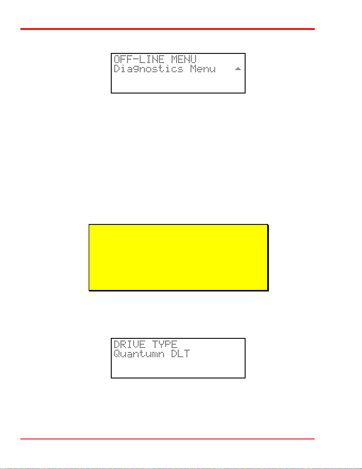
One of the most valuable features of the Scalar Library is the extensive built-in diagnostics. In this Appendix we
discuss each of the Diagnostic functions available through the front panel keypad.
The following functions are available under the Diagnostics Menu:
l Drive Type l Error Counters
l Event Counters l Operation Log
l F/W Revision l Position Picker at Slot
l Position Picker at Mailbox (When Mailbox-equipped) l Position Picker at Drv
l Pick From Slot l Pick From Mailbox (When Mailbox-equipped)
l Pick From Drv l Place In Slot
l Place In Mailbox (Scalar 458 only) l Place In Drv
l Map Slots l Calibrate X and Y
l Test Secondary Fan l Open Drive Door
l Close Drive Door
Warning
We highly recommend that these diagnostic functions be used only by a
qualified service technician (or on the instruction of a qualified
technician). Some of these functions assume that the unit has been set
up correctly and thus many of the normal built-in safety checks are
turned off. Misusing these diagnostic functions without the normal
safety checks could result in improper operation (or even damage to
media or the Scalar Library).
Drive Type
Provides a listing of the type of drives installed in the Scalar Library system. Although the Scalar Library is only
available with Quantum DLT drives at this time, this may change in the future.
52 Diagnostics Menu
Page 63
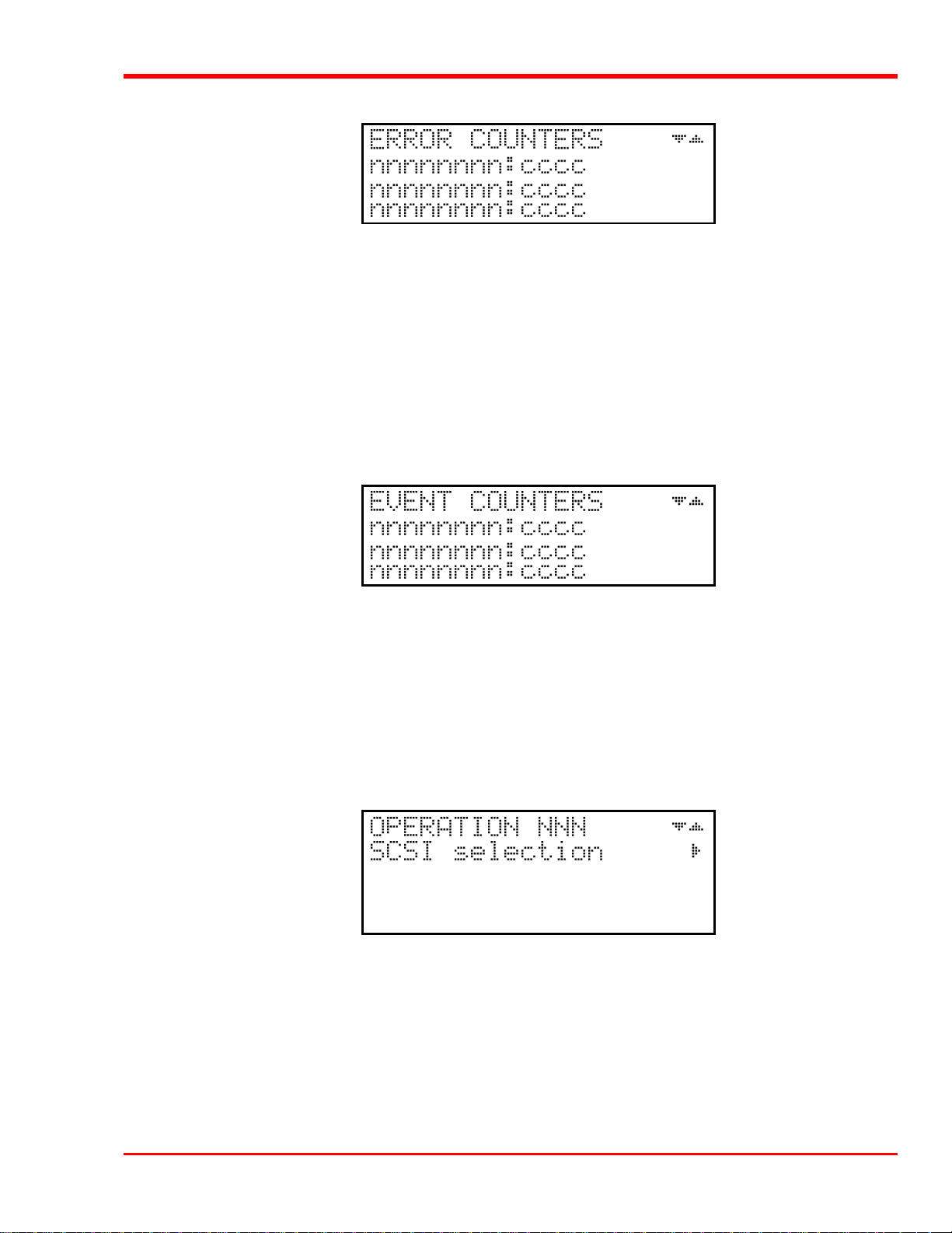
Error Counters *
Provides a chronological listing (beginning with the last error issued) of the errors encountered by the Scalar
Library system. These are library internal hardware/firmware errors. This register records each error name and
assigns it a sequential number. Below is a listing of Error Counter listings with an indication of what each refers
to:
nnnnnnnn = Counter name
cccc = Counter value (0 - 65535)
* Not implemented at this time.
Event Counters *
Provides a listing of the various Scalar Library operations and how many times they have occurred. Below is a
listing of Event Counter listings with an indication of what each refers to:
nnnnnnnn = Counter name
cccc = Counter value (0 - 65535)
* Not implemented at this time.
Operation Log *
Provides a chronological logging (beginning with the latest) of up to 255 operations. These operations can be
SCSI commands, operator requested operations, errors, and status operations. This information can be vital for
trouble shooting problems. The following is a partial listing of some of the loggable operations. You may
encounter other operations not included here.
* Not implemented at this time.
NNN = Logged operation number (1-255). When log is full, new
operations are logged in as operation 255, scrolling the
Diagnostics Menu 53
Page 64
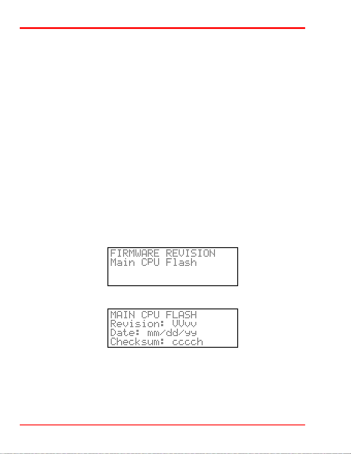
old operation 1 off the log.
Power on or user reset
Unit on-line due to user request
Unit off-line due to user request
Cmd: 03 00 00 00 20 00 (cmd is from SCSI host adapter)
SCSI selection by SCSI ID N (N = SCSI ID of host adapter)
SCSI reselection of SCSI ID N
SCSI disconnect from SCSI ID N
SCSI status = 00h (status to SCSI host adapter)
Door opened
Door closed
Load from MB row rr, slot ss to row rr, drv dd
Unload from row rr, drv dd to row rr slot ss
ERROR: Can’t unload, media in drive(s)
ERROR: Source location empty
ERROR: Unexpected Gripper Arm Sensor brk
Retrying operation
Firmware Revision
Provides a record of the internal revision date and number, and internal checksum value of the firmware for the
Main CPU, Picker CPU, and Servo Controller. This information is vital for trouble shooting problems.
p Press ENTER to list the F/W revision information for the Main CPU.
VV = Major version number (00-99)
vv = Minor version number (00-99)
mm = Build date month (01-12)
dd = Build date day (01-31)
yy = Build date year (00-99)
cccc = Internal checksum (0000-FFFF) [hexadecimal]
54 Diagnostics Menu
Page 65

p Press ESC to return to the FIRMWARE REVISION main screen.
p Press the DOWN arrow key to bring up the Picker CPU selection.
p Press ENTER to select the Picker CPU.
p Press ESC to return to the FIRMWARE REVISION main screen.
p Press the DOWN arrow key to bring up the Servo Controller CPU selection.
p Press ENTER to select the Servo Controller.
p Press ESC twice to return to the Diagnostics Menu main screen.
Position Picker at Slot
The Position Picker at Slot function is used to position the Media Picker at a particular cartridge storage slot in
preparation to either pick a cartridge from the slot, or place a cartridge into the slot.
p Use LEFT r RIGHT to select the desired field. Select the row or slot using UP or DOWN Press ENTER to
activate.
Diagnostics Menu 55
Page 66
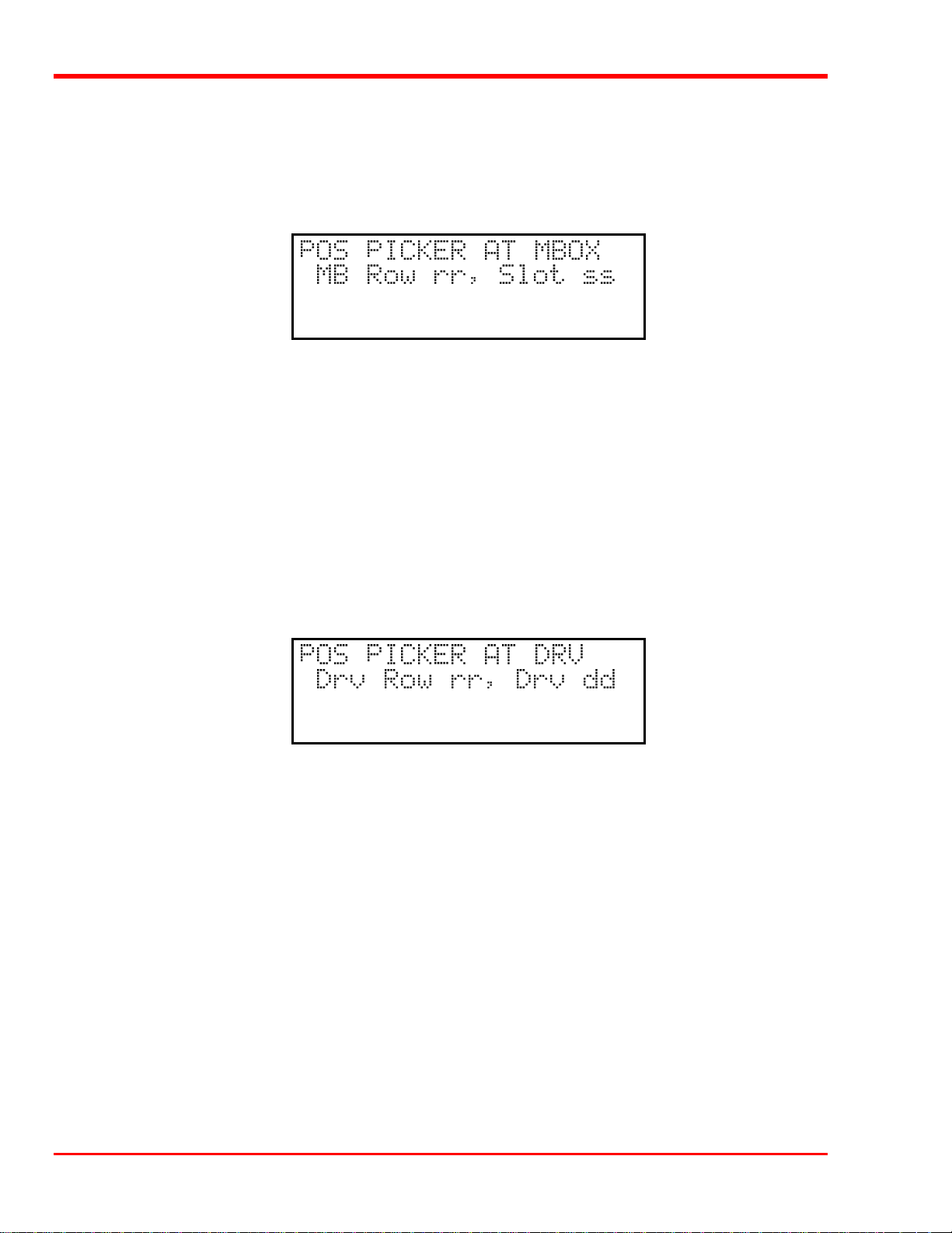
rr = Row number (01 - 4)
ss = Slot number (01 - 12)
This function is usually used for diagnostics only by a trained technician.
Position Picker at Mbox (when Mailbox equipped)
The Position Picker at MBox function is used to position the Media Picker at a particular cartridge slot of the
Mailbox (Media Interchange Shelf) in preparation to either pick a cartridge from the slot, or place a cartridge into
the slot.
p Use LEFT or RIGHT to select the desired field. Select the row or slot using UP or DOWN. Press ENTER to
activate.
rr = Row number (01 - 02)
ss = Slot number (01 - 05)
This function is usually used for diagnostics only by a trained technician.
Position Picker at Drv
The Position Picker at Drv function is used to position the Media Picker at a drive in preparation to either pick
a cartridge from the drive, or place a cartridge into the drive.
p Use LEFT or RIGHT to select the desired field. Select the row or slot using UP or DOWN. Press ENTER
to activate.
rr = Row number (01 - 2)
dd = Drive number (01 - 04)
This function is usually used for diagnostics only by a trained technician.
56 Diagnostics Menu
Page 67
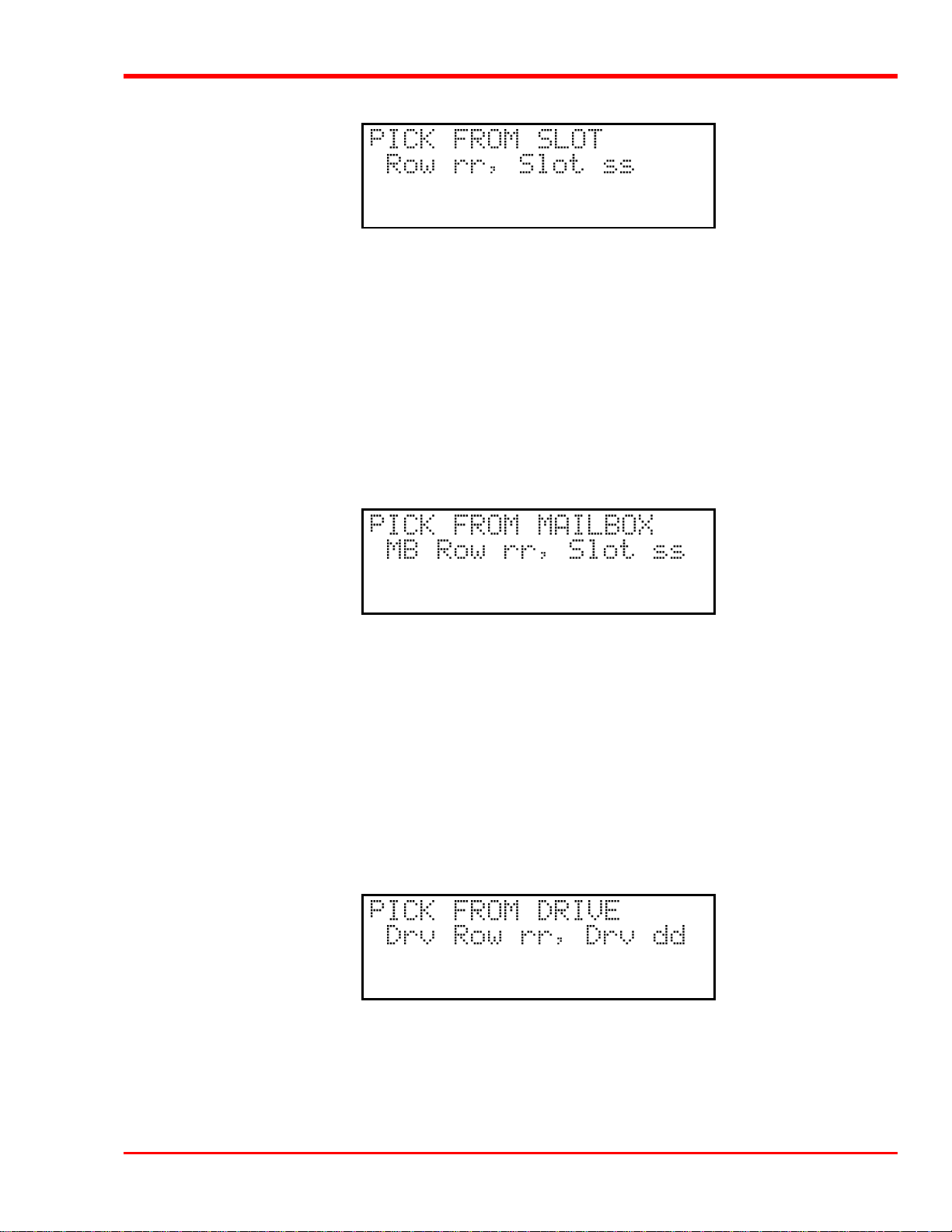
Pick From Slot
The Pick From Slot function will cause the Media Picker to pick the cartridge from a particular cartridge storage
slot in preparation to place it either in another storage slot, into a Mailbox slot, or in a drive.
p Use LEFT or RIGHT to select the desired field. Select the row or slot using UP or DOWN. Press ENTER
to activate.
rr = Row number (01 - 04)
ss = Slot number (01 - 12)
This function is usually used for diagnostics only by a trained technician.
Pick From Mailbox (when Mailbox equipped)
The Pick From Mailbox function will cause the Media Picker to pick the cartridge from a Mailbox slot in
preparation to place it either in another Mailbox slot, in a storage slot, or in a drive.
p Use LEFT or RIGHT to select the desired field. Select the row or slot using UP or DOWN. Press ENTER
to activate.
rr = Row number (01 - 2)
ss = Slot number (01 - 05)
This function is usually used for diagnostics only by a trained technician.
Pick From Drive
The Pick From Drive function will cause the drive to unload and eject the cartridge and the Media Picker to pick
the cartridge in preparation to placing the cartridge either in a storage slot or in a Mailbox slot.
p Use LEFT or RIGHT to select the desired field. Select the row or slot using UP or DOWN. Press ENTER to
activate.
Diagnostics Menu 57
Page 68
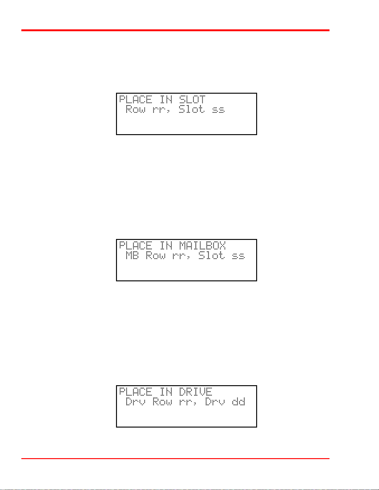
rr = Row number (01 - 2)
dd = Drive number (01 - 04)
This function is usually used for diagnostics only by a trained technician.
Place In Slot
The Place In Slot function will cause the Media Picker to place the cartridge into a storage slot.
p Use LEFT or RIGHT to select the desired field. Select the row and slot using UP or DOWN. Press ENTER
to activate.
rr = Row number (01 - 04)
ss = Slot number (01 - 12)
This function is usually used for diagnostics only by a trained technician.
Place In Mailbox (when Mailbox equipped)
The Place In Mailbox function will cause the Media Picker to place the cartridge into a Mailbox slot.
p Use LEFT or RIGHT to select the desired field. Select the MB row and slot using UP or DOWN. Press
ENTER to activate.
rr = Row number (01 - 2)
ss = Slot number (01 - 05)
This function is usually used for diagnostics only by a trained technician.
Place In Drive
The Place In Drive function will cause the drive door to open and the Media Picker to place the cartridge into the
drive.
58 Diagnostics Menu
Page 69
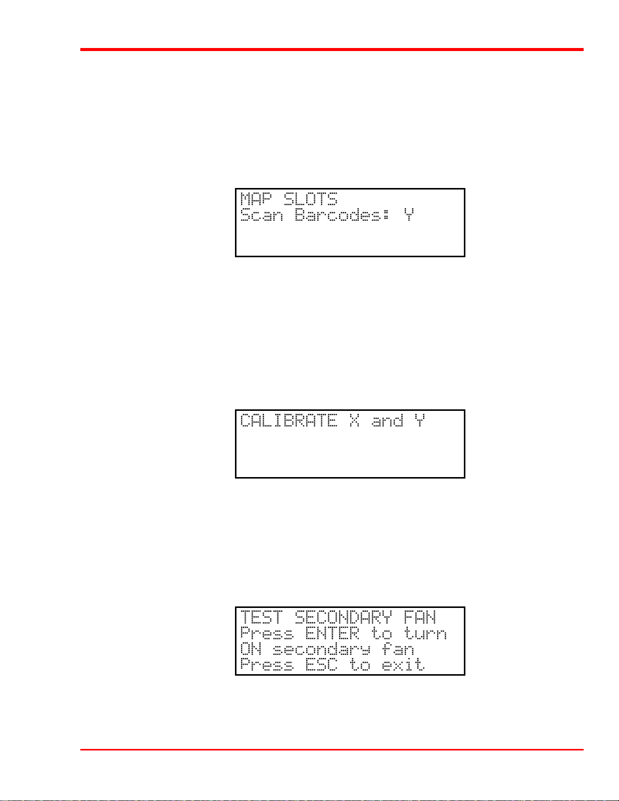
p Use LEFT or RIGHT to select the desired field. Select the drive row and drive using UP or DOWN. Press
ENTER to activate.
rr = Row number (01 - 2)
dd = Drive number (01 - 04)
This function is usually used for diagnostics only by a trained technician.
Map Slots
The Map Slots function will cause the Scalar Library to update its cartridge inventory log. Selecting “N” in the
Scan Barcodes field will prevent the library from updating its barcodes inventory log. If the Barcode Scanner
configuration parameter is set to “N”, the setting of the Scan Barcodes field is ignored.
p Use LEFT or RIGHT to select the Scan Barcodes field. Use UP or DOWN to select Y or N. Press
ENTER to activate.
This function is usually used for diagnostics only by a trained technician.
Calibrate X and Y
The Calibrate X and Y function will cause the Scalar Library to move the Media Picker to the home position (x
= left, y = bottom) and update its home position constant.
p Press ENTER to activate.
This function is usually used for diagnostics only by a trained technician.
Test Secondary Fan
The Test Secondary Fan function will cause the Scalar Library to turn the secondary cooling fan on or off.
Exiting this function via either the ESC or MENU key will turn off the secondary fan, unless the thermal IC on the
Main Controller board reads 45º C or more.
Diagnostics Menu 59
Page 70
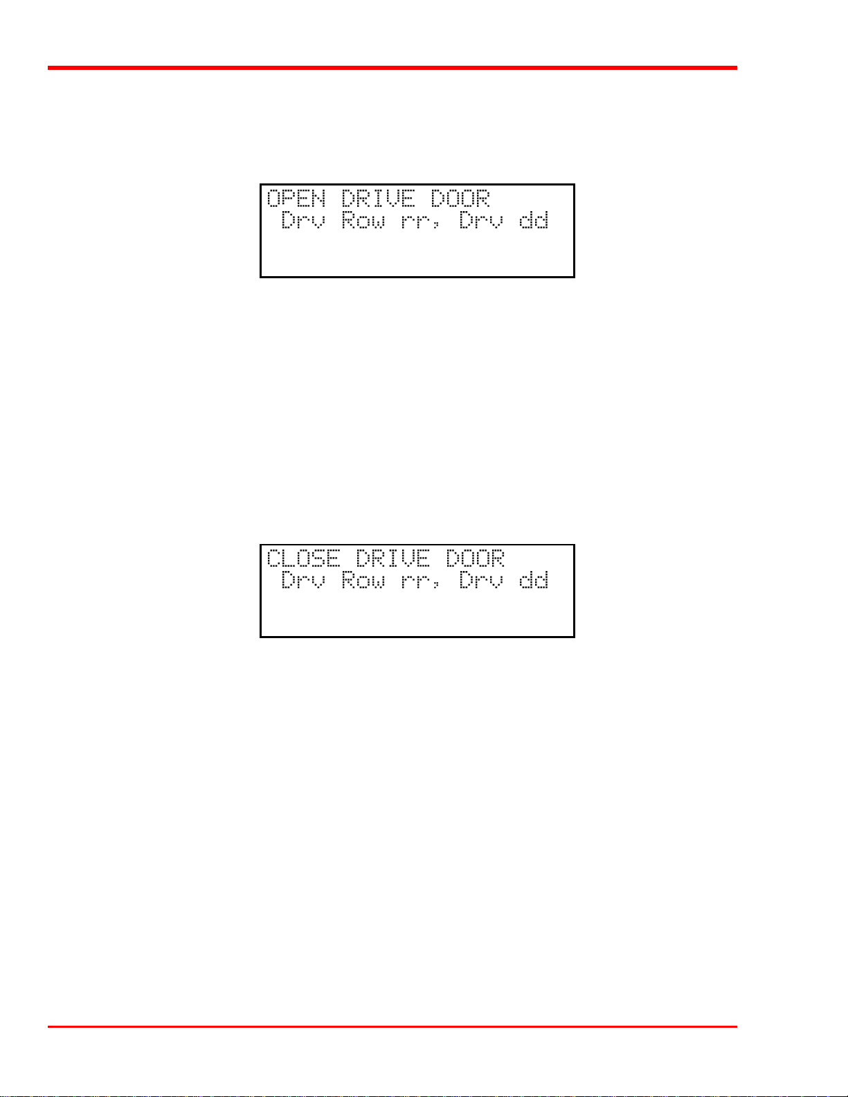
p Press ENTER to turn the secondary cooling fan on or off.
This function is usually used for diagnostics only by a trained technician.
Open Drive Door
The Open Drive Door function will cause the Scalar Library to open the door of the selected drive. If the door is
already open the drive door motor will run for a short time. If a tape is present in the drive, and it has not been
logically unloaded, as error will occur and an error message will be displayed on the Operators Panel.
p Use LEFT or RIGHT to select the desired field. Select the drive row and drive using UP or DOWN. Press
ENTER to activate.
rr = Row number (01 - 2)
dd = Drive number (01 - 04)
This function is usually used for diagnostics only by a trained technician.
Close Drive Door
The Close Drive Door function will cause the Scalar Library to close the door of the selected drive. If the door
is already closed the drive door motor will run for a short time.
p Use LEFT or RIGHT to select the desired field. Select the drive row and drive using UP or DOWN. Press
ENTER to activate.
rr = Row number (01 - 2)
dd = Drive number (01 - 04)
This function is usually used for diagnostics only by a trained technician.
60 Diagnostics Menu
Page 71

Glossary
Appendix
B
This Appendix …
p contains terms and definitions of common expressions used with the Scalar Library
and the DLT drive.
61
Page 72

cartridge
A storage medium item. A cartridge is sometimes called a tape or
cassette and is capable of storing vast amounts of magneticallywritten data. The DLT drives in the Scalar Library uses
CompacTape III, IIIXT, and/or IV cartridges.
cleaning cartridge
DLT
DLT media cartridge
DLT drive
FCC
HSM
LCD
Media used to clean the drive heads and tape path.
DLT (Digital Linear Tape) is the industry-standard data
interchange recording format that supports the use of DLT for
computer applications.
Media used with the DLT drive in the Scalar Library unit. It is a 4inch cartridge containing either 1100 or 1800 feet of ½-inch metalparticle tape. These cartridges require no formatting or other media
conditioning before use.
Drive used in the Scalar 448.
Federal Communications Commission
Hierarchical Storage Management – a system where different types
of storage medium are used based on cost and time efficiency. For
example, for fastest access, data is usually stored on a local drive.
If you have a very large file that is needed occasionally, you may
store it on a tape in the Scalar 448, or on an optical drive. In an
HSM system, the data source should be transparent to the user.
Liquid Crystal Display, a commonly used alphanumeric display
that responds to specified input voltages and signals
LED
load
POST
RMA
RMA number
SCSI
SCSI ID
Light Emitting Diode, a commonly used semiconductor device that
glows when supplied with a specified voltage.
The process where the Scalar Library uses the Media Picker to
pick a cartridge from either a cartridge storage slot location, or
from a Mailbox (Scalar 458 only) slot and load it into a drive.
Power-On Self-Test is a built-in self-test for the DLT drive. POST
automatically occurs each time the Scalar Library powers up.
Return Merchandise Authorization.
An identifying number given to a customer who needs to return
equipment for repair, whether under warranty or not.
Small Computer System Interface. An industry standard for
connecting peripheral devices and their controllers to a
microprocessor. The SCSI defines both hardware and software
standards for communication between a host computer and a
peripheral.
The octal representation of the unique address (0 to 7) assigned to
a SCSI device.
62 Glossary
Page 73

SCSI bus
Signal path or line shared by the devices on the same SCSI
channel. Information is often sent to all devices throughout the
same bus; only the device to which it is addressed will accept it.
slot
terminator
unload
A slot is the place within the cartridge storage area, or the Mailbox
(Scalar 458 only), where the media is placed. Each slot has a
reference position, i.e. row 1, position 1 through position 12
(storage slots) and row 1, position 1 through 10 (Mailbox).
a physical block which tells the SCSI bus that this is the end of the
line. A terminator is required at both ends of a SCSI bus. A bus
may be terminated internally (on a device inside the host system)
or externally on a peripheral device.
The process where the Scalar Library causes a drive to eject a
cartridge, then uses the Media Picker to move the cartridge to
either a storage slot location, or to a slot in the Mailbox.
Glossary 63
Page 74

Blank Page
64 Glossary
Page 75

Specifications
Appendix
C
This Appendix …
p contains specification information on the Scalar Library and the DLT drive.
65
Page 76

Drive:
Type:
Data Capacity: Up to 30 GB per 1800 ft cartridge (DLT2000XT)
Data Transfer Rate: 2.5 MB/sec. sustained (600 MB/min., 4 DLT2000XT drives)
Quantum® model DLT2000XT
Quantum® model DLT4000
Quantum® model DLT7000
Up to 40 GB per 1800 ft cartridge (DLT4000)
Up to 70 GB per 1800 ft cartridge (DLT7000)
Up to 1.68 TeraBytes – Scalar 224 (with 24 cartridge slots full)
Up to 3.36 TeraBytes – Scalar 448/458 (with 48 cartridge slots full)
3.0 MB/sec. sustained (720 MB/min., 4 DLT4000 drives)
5.0 MB/sec. sustained (1.2 GB/min., 4 DLT7000 drives)
Library:
Media type: DLT ½-inch, metal-particle cartridges
Cartridge Change: 8 seconds
Indicators/Controls: 8 key keypad with LCD menu display, 2 LOCKED LEDs, to monitor and control
system status, diagnostics and configuration
Interface: SCSI-2, Fast SCSI-2, Differential Serial
Reliability:
Maintenance:
MSBF: Greater than 1,000,000 cartridge changes (net, drive and media) with scheduled
MTBF: More than 50,000 power-on hours
Use cleaning cartridge whenever Use Cleaning Tape message is announced on a
drive front panel
maintenance.
MTTR: Within 30 minutes
Physical:
Dimensions: 19.0" (w) x 23.0" (d) x 40.5" (h)
Weight: 151 lb. (Scalar 458 w/2 drives)
Shipping Weight: 307 lb. (Scalar 458 w/2 drives)
Power Consumption:
Less than 100 Watts
Environment:
Electrical: 100-120/220-240 Vac, 4.0/2.0 Amps, 50/60 Hz
Temperature: 25° C to 40° C (Operating)
-40° C to 70° C (Storage/Shipping)
Humidity: 5% to 80% RH, non-condensing (Operating)
90% maximum (Storage/Shipping)
Vibration: 0.3 g peak, 5-500 Hz, swept sine; 0.0002 g (sq.)/Hz, 5-350 Hz (Operating)
0.01 g continuos, 0.50 g peak (Storage/Shipping)
Shock: 3 g for 15 ms, ½ sine (Operating)
20 g peak 3 ms ½ sine (Storage/Shipping)
66 Specifications
Page 77

Error Codes
Appendix
D
This Appendix …
p contains descriptions of the error codes that can be displayed on the Scalar Library
Operator’s Panel.
67
Page 78

Error Code Listing
The Scalar Series Libraries will display a 2-digit hex code on the bottom line of the LCD whenever certain types
of errors occur. The characters will be placed in the first 2 columns on the line. A description of each of the error
codes is provided below:
Scalar Series Error Codes
Code Name Description
06 S_EMPTY
07 D_FULL
0C DOOR_OPEN
0D DOOR
12 LOST_CASS
27 INV_PICK_RESP
28 DRV_RDY_TIMEOUT
29 NO_DRIVE
2A PICK_NO_RESP
2B PICK_CMD_TIMEOUT
The source location was empty when the Picker attempted to pick from
it during a pick and place operation.
The destination was full when the Picker attempted to place a cartridge
in it during a pick and place operation.
This code is displayed whenever the door is open when the Picker is
starting to execute a motion command.
Means that the door was open, but is now closed. This code will only
appear on the serial port, it should never appear on the display. It
should never be output on the serial port unless it is preceded by a 0C
(see above).
A pick from Mailbox failed to pick a cartridge. This code is picker
revision dependent. Only early pickers will display this code.
This error code appears whenever the Picker cpu does not return the
proper response to a Master cpu command.
This error appears whenever the ‘OK to Operate Handle’ bit is not set
within a specific time-out period.
During Power-up the drive did not output a serial data stream. This
normally occurs during the Scalar boot process.
This error code appears whenever the Picker cpu does not return any
response to a Master cpu command.
This error appears whenever the Picker cpu does not return results from
executing a command within a time-out limit.
2C BARCODE_FAIL
2D MB_DOOR_OPEN
32 X_POSITION
33 Y_POSITION
FE or 7E FRAME_ERR
FD or 7D JAW_CTR_ERR
FC or 7C NOT_EMPTY_ERR
68 Error Codes
All barcode errors return this code.
One or both of the Mailbox doors were open when a Mailbox pick and
place operation was attempted.
An X-Position Error will occur whenever the X position reported by the
servo cpu does not match the position reported by the x-axis optical
tachometer plus or minus a margin value.
A Y-Position Error will occur whenever the Y position reported by the
servo cpu does not match the position reported by the y-axis optical
tachometer plus or minus a margin value.
An inter-processor communications error on the serial communications
line.
Picker jaw centering error. May be caused by something blocking the
jaw.
The Picker attempted a pick operation but already had a cartridge in it.
Page 79

FB or 7B LOST_CART_ERR
The Picker should already have a cartridge, but no cartridge is present.
FA or 7A NO_CART_ERR
F9 or 79 CANT_PLACE_ERR
F8 or 78 UNK_PICK_POS_ERR
F6 or 76 PICK_CNTR ERR
F5 or 75 PICK_TO_ERR
F4 or 74 CART_JAM_ERR
F3 or 73 CART_TO_ERR
F2 or 72 JAW_FROZ_ERR
F1 or 71 JAW_TO_ERR
F0 or 70 JAW_POS_ERR
EF or 6F JAW_LIMIT_ERR
The Picker attempted a place operation, but no cartridge was present in
Picker.
The Picker attempted a place operation, but the Picker carriage could
not get to the correct location.
The Picker carriage is not where it should be and the Picker cannot
return it to a known location.
The Picker attempted to center the carriage, the jaw, and the gripper,
but one or more of them would not center.
The Picker attempted a pick operation, but could not complete the
operation and timed-out.
This is a roller time-out error that occurs when the picker is rolling a
cartridge out.
This is a roller time-out error that occurs when the picker is rolling a
cartridge in.
The jaws do not move at all.
The jaws are able to move, but cannot complete a function.
The jaws are not in the proper position.
The jaws are moving and expecting to see sensor feedback to know
when to stop movement, but the servo processor says that the jaws have
reached a limit first.
EE or 6E MAIL_EMPTY_ERR
ED or 6D BC_TO_ERR
EC or 6C SYS_FAULT_ERR
EB or 6B PICK_POS_ERR
EA or 6A BARCD_TERM_ERR
E9 or 69 BARCD_RX_ERR
Attempted Mailbox pick operation, but no cartridge is present.
The barcode reader did not return the barcode data in time.
This indicates that a Picker controller board error occurred.
The Picker carriage is in the wrong position.
This is an acknowledgment of a barcode read abort command.
This is caused by any serial data stream formatting error.
Error Codes 69
Page 80

Blank Page
70 Error Codes
Page 81

Index
71
Page 82

—1—
10.0 format, 34
10.0 GB tape format, 4
15.0 format, 34
—2—
2.6 format, 34
2.6 GB tape format, 4
20.0 format, 34
—6—
6.0 format, 34
6.0 GB tape format, 4
—A—
application software, 3, 4, 6, 16, 24, 30, 31, 36, 38, 41,
46
archiving, 2
density selection mode, 34
Determining Your SCSI Configuration, 12
diagnostic firmware, 4
diagnostic results, 4
Diagnostics Menu, 22, 26, 38, 39, 50
Differential SCSI, 4
Digital Linear Tape, 3, 60
DLT drives, 4, 30, 31, 35, 46, 60
Downloadable Firmware, 4
Drive Data Capacity, 64
Drive Data Transfer Rate, 64
drive head cleaning, 4
Drive Operating Conditions, 33
drive operating status, 4
Drive Power on Self Test, 32, 33, 34
Drive Power-on Self-Test, 31
Drive SCSI ID Rotary Switches, 20
Drive Status, 32
Drive Type, 22, 64
dust contamination, 42
—E—
—B—
backup operations, 30
backup software, 6, 8, 10, 16
bail locks, 15, 46
bar code label, 3
Bar Code Scanner, 3
barcode label, 36, 37
barcode labels, 6, 7
Built-in Diagnostics, 4
Buzzer Configuration, 22
Buzzer Configuration option, 23
—C—
Calibrate X and Y, 22
Calibrate X and Y function, 57, 58
cartridge inventory, 30, 31
Cartridge Pre-Check, 4
Causes of the Use Cleaning Tape Warning, 42
cleaning a drive head, 21
cleaning cartridge, 3, 6, 8, 21, 41, 60, 64
cleaning cycle, 8, 41, 42
Cleaning Tape, 40
Cleaning the Drive Head, 40
Cleaning the Enclosure, 43
Compression mode, 34
Configuration Menu, 9, 22, 23
Copyright Notice, ii, iii
embedded data logging of drive errors, 4
embedded data logging of operational errors, 4
EMI/RFI Compliance, iv
EMI/RFI limit specifications, iv
Enable Security, 22
Environmental Considerations, 47
Error Counters, 22
Error Counters function, 51
Event Counters, 22
Event Counters function, 26, 50, 51
Exabyte Emulation, 3
—F—
F/W Revision function, 26, 50, 52
failure analysis, 4
formatted capacity, 3
Front Panel Switches and Indicators, 18
—H—
Head Cleaning Procedure, 41
hierarchical storage management, 2, 60
high humidity, 42
host adapter, 6, 10, 52
host computer, 4, 6, 10, 12, 13, 16, 20, 31, 36, 60
HSM, 2, 60
—I—
data reliability, 3
data storage software, 10
72 Index
—D—
I/O connector, 10, 46
Init Scan Barcodes, 22
installation of firmware updates, 4
Installation Problems, 46
Page 83

Installing SCSI Cables Jumpers and Terminators, 12
Installing the Backup Software, 16
interchange compatibility, 4
interface cable, 12, 20
—L—
Library and Drive Operational Problems, 46
Library Cartridge Change Time, 64
library cartridge inventory, 3
Library Error Messages, 47
Library Indicators/Controls, 64
Library Interface, 64
Library media type, 64
Loading a Cartridge into Drive, 36, 37, 41
LOCKED LEDs, 3
—M—
Manual Cartridge Use, 4
Manually Loading/Unloading a Cartridge to/from the
Storage Shelves, 39
Map Slots, 22
Map Slots funciton, 26, 50
Map Slots function, 57
media access, 3
media cartridge handling mechanism, 3
media durability, 3
Media Picker, 3, 4, 7, 36, 37, 38, 53, 54, 55, 56, 60, 61
media transport operation, 36
Moving a Cartridge to/from the Storage Shelves, 39
—N—
Pick From Drive function, 26, 38, 50, 55
Pick From Mailbox function, 26, 37, 38, 39, 50, 55
Pick From Slot, 22
Pick From Slot function, 26, 39, 50, 55
pick or place operation, 39
Place In Mailbox function, 56
Place In Drive, 22
Place In Drive function, 26, 37, 50, 56
Place In Mailbox, 22
Place In Mailbox function, 26, 39, 50
Place In Slot, 22
Place In Slot function, 26, 39, 50, 56
Pos Picker at Drv, 22
Pos Picker at MBox, 22
Pos Picker at Slot, 22
Position Picker at Drive function, 26, 50, 54
Position Picker at Mailbox function, 26, 50, 54
Position Picker at Slot function, 26, 50, 53
POST, 60
Power Up Checks, 30, 31
Powering on the System, 16
Power-on Self-Test, 31, 32, 60
Preparing the Library for Installation, 7
Product Sign-On, 22
Product Sign-On Option, 24
—R—
Rear Panel Switches and Connectors, 20
restore operations, 30
Return Merchandise Authorization, 60
Reverse Cartridge Protection, 4
RMA number, 60
near-line data storage, 2
necessary tools, 6
Normal Maintenance, 40
Normal Operations, 30
—O—
off-line data storage, 2
Off-Line Mode, 9, 24, 37, 38
Off-Line Mode menu, 23
Off-Line Mode Menus, 22
Off-Line Time, 22
Off-Line Time option, 24
On-Line Mod, 47
On-Line Mode, 23, 24, 30, 31, 36, 37, 38, 39, 41, 47
operating environment, 6
Operation Log, 22
Operation Log function, 26, 50, 51
—P—
pick and place operations, 36, 37
Pick From Drive, 22
—S—
SCSI adapter, 46
SCSI Adapter Card Installation, 46
SCSI adapters, 46
SCSI bus, 9, 12, 31, 61
SCSI bus configuration, 46
SCSI Bus Jumpers, 6
SCSI bus terminator, 6
SCSI buses, 3, 9, 12, 13, 46
SCSI cable, 15
SCSI cables, 12, 13, 46
SCSI Cabling, 46
SCSI chain, 10
SCSI channel, 20, 61
SCSI configuration, 12, 13
SCSI configurations, 13
SCSI connections, 6
SCSI connector, 12
SCSI connectors, 12
SCSI controller, 6
SCSI device, 46
SCSI devices, 3, 9, 12
Index 73
Page 84

SCSI host adapter, 52
SCSI I/O Connectors, 20
SCSI ID, 20, 24, 52, 60
SCSI ID Config, 22
SCSI IDs, 46
SCSI interface, 6, 10
SCSI interface cables, 6, 15, 16
SCSI jumpers, 13, 20
SCSI termination, 46
SCSI terminator, 16, 31, 61
SCSI terminators, 12, 13, 20
Serial Dnld Flash Mode, 22, 27
Serial Number, 22
Serial Number function, 26, 50
Set Password, 22
Set SCSI ID, 22
Set SCSI ID option, 9, 24
Set Security, 22
Setting the SCSI IDs, 9
shielded data cables, iv
space requirements, 6
streaming tape cartridge, 3
surrounding environment, 6
sustained data transfer rate, 3
System security, 3
—T—
tape density, 4
—U—
Unloading a Cartridge from Drive, 36, 38, 41
Use Cleaning Tape warning, 30, 64
Using the Mailbox, 36, 41
—V—
valid cartridge locations, 4
—W—
warranty, ii, iii, 6, 8, 41, 60
What Happens When Door is Opened, 31
When You Call ADIC Customer Assistance, 48
Write Flash Memory Mode, 22, 26
Write-Protect Switch, 7, 35, 36, 37, 47
write-protect switches, 7
74 Index
 Loading...