

Page 1

Installation
and
Operating Guide
DS9000 Series
Page 2

Copyright Notice
Copyright ADIC 1995, 1996, 1997, 1998, 1999, 2000, 2001
¤
The information contained in this document is subject to change without notice.
This document contains proprietary information that is protected by copyright. All rights are reserved. No part of this
document may be photocopied, reproduced or translated to another language without the prior written consent of
ADIC.
ADIC shall not be liable for errors contained herein or for incidental or consequential damages (including lost
profits) in connection with the furnishing, performance or use of this material whether based on warranty, contract,
or other legal theory.
Printed in the U.S.A.
April 2001
Document Number 62-0101-01 Rev. H
Advanced Digital Information Corporation
Telephone: (425) 881-8004
Fax: (425) 881-2296
World-Wide Web: http://www.adic.com
Shipping Address: 11431 Willows Road NE
Redmond, WA 98052
Mailing Address: P.O. Box 97057
Redmond, WA 98073-9757
ADIC Europe
ZAC des Basses Auges
1, rue Alfred de Vigny
78112 - Fourqueux, FRANCE
Telephone: +33 (0)1 30 87 53 00
Fax: +33 (0)1 30 87 53 01
For Customer Assistance:
In the United States and Canada, call ADIC Technical Assistance Center (ATAC)
at (800) 827-3822
In Europe, call ADIC Technical Assistance Center (ATAC) at +800.9999.3822
ADIC™ and ADIC Europe™ are trademarks of Advanced Digital Information Corporation. Quantum
registered trademark, DLT™ and DLTTape™ are trademarks of Quantum Corporation.
®
is a
ii
Page 3

Copyright Notice (Europe)
© Copyright ADIC Europe 1995, 1996, 1997, 1998, 1999, 2000, 2001
All rights reserved. No part of this document may be copied or reproduced in any form or by any means, without
prior written permission of ADIC Europe, ZAC des Basses Auges 1, rue Alfred de Vigny 78112 - Fourqueux,
FRANCE.
ADIC Europe assumes no responsibility for any errors that may appear in this document, and retains the right to
make changes to these specifications and descriptions at any time, without notice.
This publication may describe designs for which patents are pending, or have been granted. By publishing this
information, ADIC Europe conveys no license under any patent or any other right.
ADIC Europe makes no representation or warranty with respect to the contents of this document and specifically
disclaims any implied warranties of merchantability or fitness for any particular purpose. Further, ADIC Europe
reserves the right to revise or change this publication without obligation on the part of ADIC Europe to notify any
person or organization of such revision of change.
Every effort has been made to acknowledge trademarks and their owners. Trademarked names are used solely for
identification or exemplary purposes, any omissions are made unintentionally.
iii
Page 4

Blank Page
iv
Page 5

Regulatory Notices
FCC Notices (USA Only)
This equipment generates, uses, and can radiate radio frequency energy and, if not installed and used in accordance
with the manufacturer’s instruction manual, may cause interference with radio and television reception. This
equipment has been tested and found to comply with the limits for a Class B digital device, pursuant to Part 15 of the
FCC Rules. These limits are designed to provide reasonable protection against harmful interference in a residential
installation. However, there is no guarantee that interference will not occur in a particular installation. If this
equipment does cause harmful interference with radio or television reception, which can be determined by turning
the equipment off and on, you are encouraged to try to correct the interference by one or more of the following
measures:
Reorient the receiving antenna.
Relocate the equipment with respect to the receiver.
Move the equipment away from the receiver.
Plug the equipment into a different outlet so that the equipment and the receiver are on different branch circuits.
If necessary, consult a representative of ADIC or an experienced radio/television technician for additional
suggestions. You may find the following booklet helpful: FCC Interference Handbook, 1996, available from the U.S.
Government Printing Office, Washington, DC 20402, Stock No. 004-000-00450-7.
This device complies with Part 15 of the FCC rules. Operation is subject to the following two conditions:
This device may not cause harmful interference.
This device must accept any interference received, including interference that may cause undesired operation.
A Notice About Shielded Cables:
to reduce the possibility of interference with radio and television reception. Using shielded cables
ensures that you maintain the appropriate FCC radio frequency emissions compliance (for a Class A
device) or FCC certification (for a Class B device) of this product.
The following information is provided on the device or devices covered in this document in compliance with FCC
regulations:
Product Name: DS9000 Series
Model number: DS9X00
Company name: Advanced Digital Information Corporation
PO Box 97057
Redmond, WA 98073-9757 USA
(425) 881-8004
v
Use only shielded cables for connecting peripherals to this device
Page 6
IC Notice (Canada Only)
Most tape libraries are classified by the Industry Canada (IC) Interference-Causing Equipment Standard #3
(ICES-003) as Class B digital devices. To determine which classification (Class A or B) applies to your tape library,
examine all registration labels located on the bottom or the back panel of your library. A statement in the form of “IC
Class A ICES-3” or “IC Class B ICES-3” will be located on one of these labels.
Note that Industry Canada regulations provide that changes or modifications not expressly approved by the tape
library manufacturer could void your authority to operate this equipment.
This Class B (or Class A, if so indicated on the registration label) digital apparatus meets the requirements of
the Canadian Interference-Causing Equipment Regulations.
Cet appareil numérique de la Classe B (ou Classe A, si ainsi indiqué sur l’étiquette d’enregistration) respecte
toutes les exigences du Reglement sur le Materiel Brouilleur du Canada.
EN 55022 Compliance (Czech Republic Only)
This device belongs to category B devices as described in EN 55022, unless it is specifically stated that it is a
category A device on the specification label. The following applies to devices in category A of EN 55022 (radius of
protection up to 30 meters). The user of the device is obliged to take all steps necessary to remove sources of
interference to telecommunication or other devices.
Pokud nenÌ na typovÈm ötitku poËÌtaËe uvedeno, ûe spad· do t¯ Ìdy A podle EN 55022, spad· automaticky do
t¯ Ìdy B podle EN 55022. Pro za¯ÌzenÌ za¯ azen· do t¯ Ìdy A (ochrannÈ p· smo 30m) podle EN 55022 platÌ
n· sledujÌcÌ. Dojde-li k ruöenÌ telekomunikaËnÌch nebo jinych za¯ ÌzenÌ, je uûivatel povinen provÈst takov·
opat¯ enÌ, aby ruöenÌ odstranil.
CE Notice
Marking by the symbol indicates compliance of this tape library to the EMC (Electromagnetic Compatibility)
directive of the European Community. Such marking is indicative that this tape library meets or exceeds the
following technical standards:
EN 55022 — “Limits and Methods of Measurement of Radio Interference Characteristics of Information Technology
Equipment.” This system is an EN 55022 Class B device.
EN 50081-1 — “Electromagnetic compatibility—Generic emission standard Part 1: Residential, commercial, and
light industry.”
EN 50082-1:1997 — “Electromagnetic compatibility—Generic immunity standard Part 1: Residential, commercial,
and light industry.”
EN 61000-3-2 — “Harmonic current emissions test.” — Device Class A.
EN61000-3-3 — “Voltage fluctuations and flicker in low-voltage supply systems test.”
EN 61000-4-2 — “Electrostatic discharge immunity test.” — Severity level 3.
EN 61000-4-3 — “Radiated, radio-frequency, electromagnetic field immunity test.” — Severity level 2.
EN 61000-4-4 — “Electrical fast transient/burst immunity test.” — Severity level 2.
EN 61000-4-5 — “Surge immunity test.” — Severity level 2.
vi
Page 7

EN 61000-4-6 — “Immunity to conducted disturbances, induced by radio-frequency fields.” — Severity level 2.
EN 61000-4-8 — “Power frequency magnetic field immunity test.” — Severity level 2.
EN 61000-4-11 — “Voltage dips, short interruptions and voltage variations immunity test.” — Performance criteria
B and C.
ENV 50204 — “Radiated electromagnetic field from digital radio telephones.”
EN 60950:1992 + Amd.1:1993 + Amd.2:1993 with considerations to Amd.3:1995 — “Safety of Information
Technology Equipment including Electrical Business Equipment.”
A “Declaration of Conformity” in accordance with the preceding standards has been made and is on file at ADIC
Europe, ZAC de Basses Auges, 1, rue Alfred de Vigny, 78112 Fourqueux, FRANCE.
vii
Page 8

DECLARATION OF CONFORMITY
according to EN 45014
Manufacturer’s Name:
Manufacturer’s Address:
declares, that the product:
Product
(Produit, Erzeugnis):
Emissions:
Immunity:
Safety:
Model Numbers
(Marque Commercial,
Warenbezeichnung):
conforms to the following international standards,
Quality:
Supplementary Information:
Advanced Digital Information Corporation
11431 Willows Road ZAC des Basses Auges
Redmond, Washington 98052 1, rue Alfred de Vigny
USA 78112 Fourqueux,
FRANCE
DS9000 Series
DS9800D
DS9700D
DS9400D/L
DS9400
EN 50081-1, EN-55022 Class B
EN 50082-1
EN 60950
ISO 9001
Signature:
Full Name:
Position:
Date:
Place:
viii
Signature on File
Redmond, WA USA
Signature:
Full Name:
Position:
Date:
Place:
Signature on File
Fourqueux, FRANCE
Page 9
Safety Notices
Warnings
CAUTION
RISK OF ELECTRIC SHOCK
DO NOT OPEN
This symbol should alert the
user to the presence of
"dangerous voltage" inside
the product that might cause
harm or electric shock.
CAUTION :
THERISKOFELECTRIC
SHOCK, DO NOT REMOVE
COVER (OR BACK).
NO USER-SERVICEABLE
PARTS INSIDE. REFER
SERVICING TO QUALIFIED
SERVICE PERSONNEL.
TO REDUCE
Caution
All safety and operating instructions should be read before this product is
operated, and should be retained for future reference. This unit has been
engineered and manufactured to assure your personal safety. Improper use can
result in potential electrical shock or fire hazards. In order not to defeat the
safeguards, observe the following basic rules for its installation, use and
servicing.
Heed Warnings - All warnings on the product and in the operating instructions should be adhered to.
x
Follow Instructions - All operating and use instructions should be followed.
x
Ventilation - The product should be situated so that its location or position does not interfere with proper
x
ventilation.
Heat - The product should be situated away from heat sources such as radiators, heat registers, furnaces, or
x
other heat producing appliances.
Power Sources - The product should be connected to a power source only of the type directed in the operating
x
instructions or as marked on the product.
Power Cord Protection - The AC line cord should be routed so that it is not likely to be walked on or pinched
x
by items placed upon or against it, paying particular attention to the cord at the wall receptacle, and the point
where the cord exits from the product.
Object and Liquid Entry - Care should be taken to insure that objects do not fall and liquids are not spilled into
x
the product’s enclosure through openings.
Servicing - The user should not attempt to service the product beyond that described in the operating
x
instructions. All other servicing should be referred to qualified service personnel.
ix
Page 10

Precautions
Do not use oil, solvents, gasoline, paint thinners or insecticides on the unit.
x
Do not expose the unit to moisture, to temperatures higher than 60ºC (140ºF) or to extreme low temperatures.
x
Keep the unit away from direct sunlight, strong magnetic fields, excessive dust, humidity and
x
electronic/electrical equipment, which generate electrical noise.
Hold the AC power plug by the head when removing it from the AC source outlet; pulling the cord can damage
x
the internal wires.
Use the unit on a firm level surface free from vibration, and do not place anything on top of unit.
x
x Safety Notices
Page 11

Table of Contents
Copyright Notice............................................................................................................................................... ii
Copyright Notice (Europe)...............................................................................................................................iii
Regulatory Notices.............................................................................................................................................v
Safety Notices...................................................................................................................................................ix
Chapter 1 Introduction.............................................................................................................................................. 1
Equipment Description...................................................................................................................................... 2
DLT Drives....................................................................................................................................................... 2
Options.............................................................................................................................................................. 2
SCSI Interface........................................................................................................................................................... 2
Front Panel Controls and Indicators.................................................................................................................. 3
Rear Panel Controls and Connectors................................................................................................................. 7
Data Cartridge................................................................................................................................................... 8
Other Requirements .......................................................................................................................................... 9
Application Software ................................................................................................................................................ 9
Chapter 2 Installation.............................................................................................................................................. 11
Unpacking and Inspecting............................................................................................................................... 12
Checking the Accessories................................................................................................................................ 12
Installing the Host Adapter ............................................................................................................................. 12
Connecting the Interface Cable ....................................................................................................................... 12
Connecting More than One DS9000 Series Unit .................................................................................................... 13
Setting the SCSI ID......................................................................................................................................... 14
Check the SCSI Bus Termination ................................................................................................................... 15
Connecting Power and Turning On................................................................................................................. 15
Installing the Application Software................................................................................................................. 16
Chapter 3 Operation and Maintenance.................................................................................................................... 17
Power-on Self-Test.......................................................................................................................................... 18
Drive Status............................................................................................................................................................. 18
Loading the Data Cartridge............................................................................................................................. 25
Data Protection................................................................................................................................................ 27
Tape in Use ..................................................................................................................................................... 27
Removing the Data Cartridge.......................................................................................................................... 28
Cleaning the Tape Head .................................................................................................................................. 28
Cleaning the Enclosure ................................................................................................................................... 30
Chapter 4 Troubleshooting and Diagnostics........................................................................................................... 31
Troubleshooting Chart .................................................................................................................................... 32
Use Cleaning Tape LED.................................................................................................................................. 34
xi
Page 12

Why the Use Cleaning Tape LED Gets Turned ON.................................................................................................34
High Humidity.................................................................................................................................................35
When Assistance is Required...........................................................................................................................36
Calling ADIC’s Technical Assistance Center (ATAC) ............................................................................................36
Appendix A Specifications ......................................................................................................................................37
Appendix B Drive Configuration.............................................................................................................................39
Index........................................................................................................................................................................45
xii Table of Contents
Page 13

Chapter
1
Introduction
This Chapter. . .
S
provides a physical description of the switches, indicators and connectors
on the front and rear panels of the DS9000 Series.
S
describes other requirements (additional hardware and software) needed
to use the DS9000 Series devices.
1
Page 14

Equipment Description
The ADIC DS9000 Series consists of several models: the ADIC 4000, DS9400D/L, DS9700D and DS9800D. All
are SCSI compatible, high performance, streaming tape cartridge devices designed for storage of near-line and offline data.
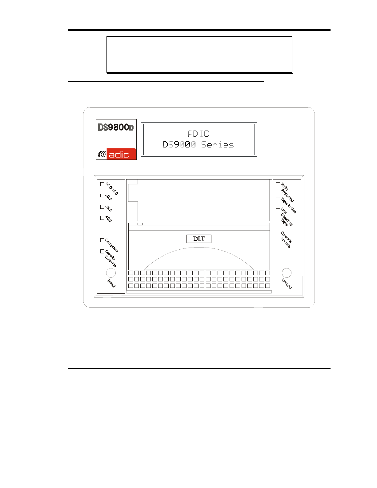
The DS9400D/L, DS9700D, and DS9800D are equipped with a 2-line by 20-character, back-lit LCD display. The
LCD displays drive status messages, error messages, and drive Power-On Self-Test (POST) results messages. The
ADIC 4000 uses the drive bezel LEDs to communicate drive operations. The DS9000 Series also includes Flash
EEPROM technology that allows easy on-site installation of firmware updates from tape or from the host.
DLT Drives
Your DS9000 Series is equipped with a third-, or fourth-generation DLT drive. The DLT4000 and DLT7000 drives
can read and write 2.6 GB, 6.0 GB, and 10.0 GB tape formats for 100% interchange compatibility with earlier DLT
drives. The DLT 8000 drive can read and write 10.0, 15.0, 20.0, and 35.0 GB tape formats for 100% interchange
compatibility with the DLT 2000, DLT 2000xt, DLT 4000, and DLT 7000 drives. DLT 8000 default tape density is
40 GB (80 GB compressed) when using the DLTTape IV data cartridge. Tape density is selectable by the application
software or via the Operator Panel.
Model Drive
Model
DS9400D/L
ADIC 4000
DS9700D
DS9800D
DLT4000 20 GB (DLTTape III)
DLT7000 20 GB (DLTTape III)
DLT8000 20 GB (DLTTape III)
Maximum Capacity and Sustained Transfer Rates
Cartridge Max Capacity
(density - compressed mode)
30 GB (DLTTape IIIXT)
40 GB (DLTTape IV)
30 GB (DLTTape IIIXT)
70 GB (DLTTape IV)
30 GB (DLTTape IIIXT)
80 GB (DLTTape IV)
Sustained Transfer Rate
(compressed mode)
3.0 MB/sec (180 MB/min)
10.0 MB/sec (600 MB/min)
12.0 MB/sec (720 MB/min)
Options
SCSI Interface
The DS9000 Series is available with several different SCSI interfaces. These include Single-Ended (SE), Low
Voltage Differential/Single-Ended (LVD/SE), or High Voltage Differential (HVD) SCSI interface.
2
Page 15
Caution
SE and LVD/SE SCSI devices are not compatible with HVD SCSI devices.
Equipment damage may occur if you connect your DS9000 Series unit to an
incompatible SCSI bus.
Front Panel Controls and Indicators
Figures 1 through 3 show the controls and indicators located on the front panel of the DS9000 Series.
Figure 1. DS9800D Front Panel
Introduction
3
Page 16
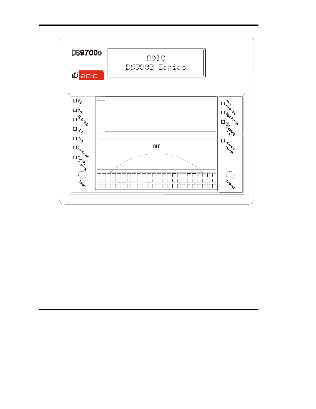
4
Figure 2. DS9700D Front Panel
Page 17
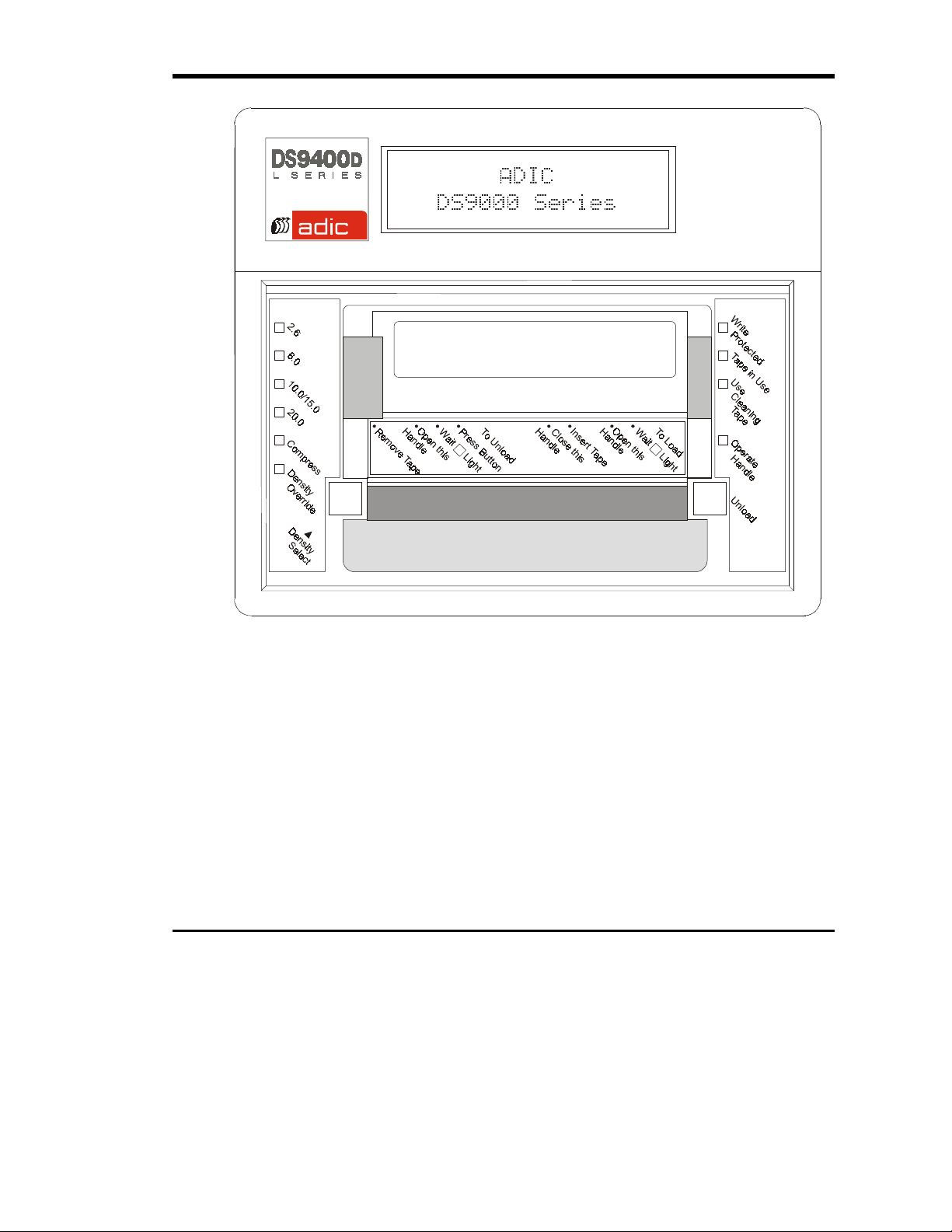
Figure 3. DS9400D/L Front Panel (ADIC 4000 does not include the LCD)
Introduction
5
Page 18

2-line by 20-character LCD
Display
Beeper
Write Protected
(orange)
Tape in Use
(yellow)
Use Cleaning Tape
Operate Handle
(green)
Density Select 2.6
(yellow)
Density Select 6.0
Density Select 10.0
(yellow)
Density Select 15.0
(yellow)
Density Select 20.0
(yellow) [DS9400D/L, ADIC
4000]
Density Select 35.0
(yellow) [DS9700D]
Density Select 40.0
(yellow) [DS9800D]
Compress
(yellow)
Density Override
Unload Button
Cartridge Insert/Release
Handle
(yellow)
(yellow)
(yellow)
Front Panel Indicators and Controls
Displays drive status, error messages, POST results
Sounds whenever it is OK to operate the cartridge insert/release handle. The green
Operate Handle LED should be ON whenever the Beeper sounds.
= Tape write-protected.
ON
= Tape write enabled.
OFF
= Tape moving.
Blinking
= Tape loaded; ready for use.
ON
= Drive head needs cleaning, or the tape is bad.
ON
= cleaning complete, or cleaning unnecessary.
OFF
= OK to operate the cartridge insert/release handle.
ON
= Do not operate the cartridge insert/release handle.
OFF
= Tape is recorded in 2.6 GB format.
ON
= Tape is recorded in another density.
Blinking
= Tape is recorded in 6.0 GB format.
ON
= Tape is recorded in another density.
Blinking
= Tape is recorded in 10.0 GB format.
ON
= Tape is recorded in another density.
Blinking
= Tape is recorded in 15.0 GB format.
ON
= Tape is recorded in another density.
Blinking
= Tape is recorded in 20.0 GB format.
ON
= Tape is recorded in another density.
Blinking
= Tape is recorded in 35.0 GB format.
ON
= Tape is recorded in another density
Blinking
= Tape is recorded in 40.0 GB format.
ON
= Tape is recorded in another density
Blinking
= Compression mode enabled.
ON
= Compression mode disabled.
OFF
= Density selected from front panel.
ON
(default) = Density selected from host.
OFF
= In density selection mode.
Blinking
Pressing this button initiates a manual unload of the tape. This may take from 10
seconds to 4 minutes depending on tape position.
Lift this handle (only when the Operate Handle LED is ON, and after the
momentary beep sounds) to load or eject a cartridge from the drive. The handle lifts
to the open position and lowers to the closed position.
6
Page 19

Rear Panel Controls and Connectors
Figure 4 shows the controls and connectors located on the rear panel of the DS9000 Series.
3
AC Power
Connector
Power
Switch
SCSI Channel
Connectors
Figure 4. DS9000 Series Rear Panel
SCSI ID
Switch
Introduction
7
Page 20

Rear Panel Controls and Connectors
Control or Connector Purpose
Power Switch
AC Power Connector
SCSI Channel Connectors
SCSI ID Switch
Data Cartridge
The data cartridges used in the DS9000 Series are housed in 4-inch plastic cases and employ ½-inch metal particle
tape. Table 4 describes and lists the media cartridges that can be used with the four models.
Model Drive Model Cartridge Model Cartridge
DS9400D/L
ADIC 4000
DS9700D DLT7000 DLTTape III
DS9800D DLT8000 DLTTape III
DLT4000 DLTTape III
Turns power to the unit on and off.
Receptacle for AC power cord.
Connections for the interface cable that connects the unit with
the host computer and/or to other devices on the SCSI channel.
The interface cable can be attached to either connector.
All DS9000 Series models, except the DS9700D and DS9800D,
are equipped with a 50-contact, shielded, low density SCSI
device connector. The DS9700D and DS9800D, both fast, wide
SCSI devices, use a 68-pin high density SCSI device connector.
Used to select the SCSI ID for the DLT drive. Factory set at 0.
DLTTape IIIXT
DLTTape IV
DLTTape IIIXT
DLTTape IV
DLTTape IIIXT
DLTTape IV
Media Cartridge
Color
gray
white
brown
gray
white
brown
gray
white
brown
Tape
Length
1100 feet
1800 feet
1800 feet
1100 feet
1800 feet
1800 feet
1100 feet
1800 feet
1800 feet
Table 4. Media Cartridges
Write-Protect
The
cartridge is write-protected and the drive cannot write to, or erase data from, the cartridge. The small orange
rectangle will be visible whenever the cartridge is write-protected. Additionally, an arrow (beneath the orange
rectangle and above the two lines on the switch), indicates when data cannot be written to the cartridge. If the switch
is moved all the way to the right, the cartridge is write-enabled and the drive can write data to, or erase data from, the
cartridge. The orange rectangle will not be visible whenever the cartridge is write-enabled. On the right side of the
write-protect switch an arrow over one line indicates that data can be written to the cartridge if it is slid to the right.
8
switch prevents accidental erasure of data. If the switch is moved all the way to the left, the
Page 21

Write-Protected
Orange
Indicator
Write-protect
Switch
Write-Enabled
Figure 5. DLT Data Cartridge
Cautions
Always remove
x
system power. Failure to remove a cartridge can result in cartridge and
drive damage.
When a cartridge is removed from the drive, return it to the plastic case to
x
prolong the cartridge life.
cartridge from the drive before turning off host
any
Other Requirements
SCSI Host Adapter
Your DS9000 Series must be connected to either an integrated SCSI host or a separate SCSI interface (host adapter)
card installed in the computer – either directly to the I/O connector on the card or as part of an existing SCSI chain.
The host adapter you choose will depend on your system requirements and your needs. If you are not sure about your
host adapter requirements, please call ADIC’s Technical Assistance Center (ATAC) and ask for assistance. The SCSI
interface must be installed before you connect the DS9000 Series.
Application Software
A variety of backup and data storage software is available for use with your DS9000 Series. The software you use
will depend upon your storage needs and the system you are using. Please check with ADIC Sales or Customer
Assistance if you have a question on the compatibility of a particular software package.
Now you are ready to connect the DS9000 Series to your host computer. Follow the instructions provided in the next
chapter.
Introduction
9
Page 22

Blank Page
10
Page 23

Installation
This Chapter. . .
S
explains the steps necessary to install and test the DS9000 Series Devices.
S
provides a symbol next to each step verified as correct.
Chapter
2
11
Page 24

Unpacking and Inspecting
Caution
If the operating environment differs from the storage environment by 15° C
(30° F) or more, let the unit acclimate to the surrounding environment for at
least 12 hours.
Unpack all items from the carton. Save the packing materials in case you need to move or ship the system in the
future.
Caution
You must ship the DS9000 Series in the original or equivalent packing
materials or your warranty may be invalidated.
Checking the Accessories
Check to make certain that the following items are included with your DS9000 Series:
• Power cord
• One DLTTape IV data cartridge
• One cleaning cartridge, or a coupon for a free DLT cleaning cartridge
• One SCSI cable
• One SCSI bus terminator
• This manual
• A Warranty Registration card
None of the items should show signs of damage.
Installing the Host Adapter
At this point if your host computer system does not have native SCSI capability and the host adapter you are using is
not installed, please install it. Refer to the manual that came with your host adapter for specific directions.
When the host adapter card is installed return to this point in the manual.
Connecting the Interface Cable
Attach an interface cable between the host adapter and the DS9000 Series. The kind of cable needed depends on the
kind of SCSI bus connector on the host adapter. The DS9000 Series has two SCSI device connectors on the rear
panel. It does not matter which connector is used.
Installation
12
Page 25

Note
p
y
DXU RQY\ \_S[c _b ZQS[cSbUgc Qd dXU U^Tc _V dXU C3C9 SQR\U ]ecd RU cUSebU\i
VQcdU^UT d_ Y^cebU S_]]e^YSQdY_^c RUdgUU^ dXU 4C) CUbYUc Q^T dXU X_cd
S_]`edUb
Make sure that the SCSI cable between the host adapter and the DS9000 Series is secure and the
connections are fastened correctly.
Connecting More than One DS9000 Series Unit
If connecting to more than one DS9000 Series unit on the same SCSI channel, connect each unit to the previous unit
with an interface cable. The connection sequence between the units is not critical. Refer to Figure 6 to see a
configuration set-up.
Note
4_^µd V_bWUd d_ Y^cdQ\\ dXU C3C9 dUb]Y^Qd_b _^ dXU \Qcd TUfYSU Y^ dXU SXQY^
4DS9X00Units
Dais
SCSI
Interface Cables
Chained
Term inato r
SCSI ID 3
SCSI ID 2
SCSI ID 1
Host Com
Installation
uter
Figure 6. Cable Diagram for 4 DS9000 Series Units
SCSI ID 0
13
Page 26

Setting the SCSI ID
The SCSI address of the DS9000 Series may need to be changed, depending upon factors in the setup, operating
system, and number of SCSI devices on the bus. Each device on the bus must have its own address. See Figures 6
and 7.
Notes
DXU C3C9 94 XQc RUU^ VQSd_bi `bUcUd d_
x
1\\ TUfYSUc _^ Q C3C9 Rec ]ecd RU cUd d_ Q e^YaeU QTTbUcc
x
SCSI ID
Switch
3
DXU 1493 $ Q^T 4C)$ 4< SQ^ RU cUd d_ Q^i C3C9 94 RUdgUU^ Q^T '
DXU 4C)' 4 Q^T 4C)( 4 R_dX VQcd gYTU C3C9 TUfYSUc SQ^ RU cUd d_ Q^i
C3C9 94 RUdgUU^ Q^T !%
Installation
14
Figure 7. SCSI ID Switch
Note
Page 27

The SCSI ID switch is located on the rear of the DS9000 Series (see Figure 7). Use a small pointed object to press
either the + button on the bottom, or the minus button on the top of the switch to select the proper ID.
Count each device's SCSI IDs in order from 0 to 7 (or from 0 to 15) on each SCSI bus to confirm that no
two devices have the same ID number assigned.
Note
DXU C3C9 8_cd 1TQ`dUb Yc ^_b]Q\\i cUd d_ C3C9 94 ' c_ dXYc 94 Yc eceQ\\i ^_d
QfQY\QR\U V_b Q TUfYSU
Check the SCSI Bus Termination
SCSI buses require termination at each end for proper operation. A typical external subsystem installation would be
terminated at the SCSI host adapter and at the last device in the chain.
If an external device is being used with an internal device (on the same channel), the SCSI host adapter would now
be in the middle of the bus rather than at the end. In this case, the termination would be at the internal device and the
last drive in the external chain. The terminators on the SCSI host adapter would be removed. Refer to the SCSI host
adapter manual for directions on removing the terminators on the board.
Is there a terminator installed on each end of the SCSI bus?
Note
1493 bUS_]]U^Tc dXQd i_e Q\gQic dUb]Y^QdU Q cY^W\UU^TUT Rec gYdX Q^ QSdYfU
dUb]Y^Qd_b
Connecting Power and Turning On
S
Plug the power cord into the back of the DS9000 Series.
S
Plug the power cord from the DS9000 Series into a GROUNDED electrical outlet.
S
Plug the power cord from the host system into the same GROUNDED electrical circuit if
possible. Computers and peripherals should always share the same grounds.
S
Turn ON the power to the host system.
S
Turn the DS9000 Series power ON.
Installation
15
Page 28

Note
Deb^Y^W _^ dXU X_cd S_]`edUb VYbcd U^cebUc dXQd dXU C3C9 Rec dUb]Y^Qd_bc
cdQRY\YjU dXU Rec cYW^Q\c RUV_bU dXU dQ`U TbYfU Yc deb^UT _^
Installing the Application Software
S
Refer to the application software installation guide and install the backup software, if
necessary.
After completing installation of the DS9000 Series unit and backup software, run a small
backup/restore test and compare the results to confirm that the unit is working correctly.
Refer to the software installation guide for additional information.
Installation
16
Page 29

Chapter
3
Operation and Maintenance
This Chapter . . .
S
describes normal operating features of the DS9000 Series.
S
explains how, and when to clean the tape head.
S
describes how to clean the enclosure.
17
Page 30

Power-on Self-Test
When the system power is ON, the DLT drive performs a Power-on Self-Test (POST). The sequence of events is as
follows:
1. The LEDs on the right front panel of the DLT drive will turn on sequentially from top to bottom. All LEDs
will remain ON for a few seconds.
2. The LEDs on the left front panel will turn ON at the same time for about three seconds and then turn
3. The
Operate Handle, Write Protected
Use
LED will blink while the tape drive initializes.
If the external SCSI bus terminator has a Term Power LED it should also be illuminated.
Use Cleaning Tape
, and
LEDs will turn
OFF
Drive Status
LED Indicators
After initialization, the drive will be in one of the four states listed in the following table:
Drive State LED Indicator Displays and Drive Actions
1. No cartridge is present.
2. A cartridge is present and the
handle is down.
3. A cartridge is present, but the
handle is up (
recommended
4. The drive detects an error
condition.
not
).
A. The
B. The
C. The handle is unlatched.
D. The drive beeps momentarily.
The drive loads the cartridge.
When the
tape’s actual density lights. For example, if the actual tape density
is 2.6, then the LED turns ON next to the 2.6 label.
When the
The drive is ready for use.
The
flashes.
When the handle is lowered, the cartridge loads.
All right or left side LEDs blink repeatedly.
Try to unload the tape (if present) and reinitialize the drive by
pressing the
ON
to reinitialize. The LEDs turn ON with a constant illumination,
and then turn
Tape in Use
Operate Handle
Tape in Use
Density Override
Tape in Use
Unload
. The right or left side LEDs stop blinking and the drive tries
OFF
LED turns
LED turns ON.
LED stops blinking and stays ON, the
LED blinks, select a density setting.
LED turns
button or switch the power
if the test succeeds.
OFF
.
OFF
Operate Handle
. The
OFF
. The
and then
OFF
Tape in
LED
.
Operation and Maintenance
18
Page 31

LCD Messages (DS9400D/L, DS9700D and DS9800D)
The following table describes the messages displayed on the LCD during and immediately after the POST:
Drive State
1. POST is executing.
2. POST completed, no cartridge
is present, and the handle is
down.
Note
This is the
for the DS9000 when
powering up.
preferred
state
LCD Message
Will be displayed for 3 to 5 seconds, followed by:
“DRV F/W” is the firmware version of the drive.
“LCD F/W” is the firmware version of the LCD controller.
“ID” is the SCSI ID setting of the drive.
“CPH” is the cumulative power on hours of the drive.
“TSL” is the time since last cleaning cycle of the drive (will reset
to zero after every cleaning cycle if followed by a power recycle).
“DCL” is the drive data cartridge load counter.
3. POST completed, a cartridge
is present, but the handle is up
(
not recommended
Note
The DS9000
be left in this state when
powering down.
4. The drive detects an error
condition.
POST completes in about 13 seconds and the drive responds normally to all commands. However, it may take longer
for the media to become ready.
Operation and Maintenance
).
should not
This message will appear after approximately 5 minutes.
19
Page 32

LED Indicators
Use the following table to determine the drive’s operating condition:
Label
Write Protected
Tape in Use
Use Cleaning Tape
Operate Handle
All Right Indicator Panel
LEDs
All Left Indicator Panel
LEDs
or,
Right Indicator Panel LED
Color State
Orange ON
Yellow Blinking
Yellow ON
Green ON
F
OFF
ON
Remains on after
unloading cleaning
tape
After cleaning, turns
on again when
reloading data
cartridge
OFF
Blinking
ON
Blinking
Operating Condition
Tape is write-protected.
Tape is write-enabled.
Tape is moving.
Tape is loaded; ready for use.
Drive head needs cleaning, or the
tape is bad.
Cleaning attempted, but tape expired,
so cleaning not performed.
Problem data cartridge. Try another
cartridge.
OK to operate the Cartridge
Insert/Release Handle.
Do not operate the Cartridge
Insert/Release Handle.
Drive was powered on with door
open. Close door and let drive
complete initialization.
POST is starting.
An error has occurred.
Operation and Maintenance
20
(Continued on next page)
Page 33

Label
(ADIC 4000, DS9400D/L,
2.6
DS9700D)
6.0
DS9700D)
10.0
DS9400D/L)
10.0/15.0 (
DS9800D)
20.0 (
DS9400D/L, DS9700D,
DS9800D)
35.0
40.0 (
Compress
Density Override
All Right Indicator Panel
LEDs, or,
all Left Indicator Panel
LEDs
(ADIC 4000, DS9400D/L,
(ADIC 4000,
DS9700D,
ADIC 4000,
(DS9700D, DS9800D)
DS9800D)
Left Indicator Panel LED
Color State
Yellow ON
Yellow ON
Yellow ON (default)
Yellow ON (default)
Yellow ON (default)
Yellow ON (default)
Yellow ON (default)
Yellow ON
Yellow ON
F
Blinking
Blinking
Blinking
Blinking
Blinking
Blinking
Blinking
OFF
OFF (default)
Blinking
Blinking A POST error has occurred.
Operating Condition
Tape is recorded in 2.6 format.
Tape is recorded in another density. The
density selection was chosen earlier from
BOT.
Tape is recorded in 6.0 format.
Tape is recorded in another density. The
density selection was chosen earlier from
BOT.
Tape is recorded in 10.0 format.
Tape is recorded in another density. The
density selection was chosen earlier from
BOT.
Tape is recorded in 10.0 or 15.0 format.
Tape is recorded in another density. The
density selection was chosen earlier from
BOT.
Tape is recorded in 20.0 format.
Tape is recorded in another density. The
density selection was chosen earlier from
BOT.
Tape is recorded in 35.0 format.
Tape is recorded in another density. The
density selection was chosen earlier from
BOT.
Tape is recorded in 40.0 format.
Tape is recorded in another density. The
density selection was chosen earlier from
BOT.
Compression mode enabled.
(Compression can be done only in 10.0,
15.0, 20.0, 35.0, and 40.0 density.)
Compression mode disabled.
A density setting was selected earlier from
the front panel.
Density will be selected by the host
(automatic).
The unit is in density selection mode.
Operation and Maintenance
21
Page 34

LCD Messages (DS9400D/L, DS9700D and DS9800D only)
The following table describes the messages displayed by the LCD during normal operation:
Drive Operating Condition LCD Message
No tape in drive.
When loading or unloading a tape.
When tape is unloaded.
“type” = 4000 OMX (DS9400D/L), 7000 OMX (DS9700D) or
8000 OMX (DS9800D).
During the loading process the display may toggle between
“Loading >>>” and “Calibrating >>>”.
Note
While loading the tape, the drive will enter a false
Ready Mode condition for a short period. During this
false state the Tape In Use LED will continue to
blink. Do not attempt any operations while the LED
is blinking.
Continued on next page.
Operation and Maintenance
22
Page 35

Drive Operating Condition LCD Message
When tape is loaded.
If write-protected tape is inserted.
Write-protected tape fully loaded.
“type” = 4000 OMX (DS9400D/L), 7000 OMX (DS9700D) or
8000 OMX (DS9800D).
“Compressed” if compression mode enabled or “Standard” if
compression mode disabled.
“15/30 GB” is drive dependent. “15/30 GB” = DLT2000XT,
“20/40 GB” = DLT4000, “35/70 GB” = DLT7000, and “40/80 GB
= DLT8000.
This is the normal “Ready Screen”.
During loading of a write-protected tape, the display will change
from:
“Loading >>>” to “Write Protected Tape Inside Drive”, the LCD
back-light will toggle on/off and an audible alarm will sound.
“WPT” = Write Protected Tape in unit.
“WPT” will toggle to “GB” and back to “WPT” and continue
toggling until next drive action.
Continued on next page.
Operation and Maintenance
23
Page 36

Drive Operating Condition
Whenever the system is writing to a
tape, these two messages will
alternate. Each message will be
displayed for approximately 2.5
seconds.
Whenever the system is reading a
tape, this message will alternate
with the ready screen.
Whenever a tape is in motion.
LCD Message
“Writing” indicates the system is writing to the tape.
“2.1:1” indicates the current compression ratio being used.
“16 GB” indicates the amount of tape still available to be
written to.
3 arrows in motion (
Reading indicates the system is reading from the tape.
Motion Messages = Loading, Unloading, Reading, Writing,
Positioning, Erasing, Cleaning and Rewinding.
3 arrows in motion (
) indicate tape travel.
) indicate tape travel.
Whenever an incorrect cartridge
type is placed into a drive (i.e.
DLTTape IV cartridge is placed in
DLT2000 or DLT2000XT drive).
Continued on next page.
Operation and Maintenance
24
The LCD will flash and the beeper will sound while this message
is displayed.
Press the Unload button, the drive will begin unloading the tape
and the LCD will return to normal operation messages.
Page 37

Drive Operating Condition LCD Message
If new tape, or the drive cannot
initialize the tape.
followed by:
followed by:
A hardware error occurs during
normal operation.
Loading the Data Cartridge
Before loading into a drive, ensure that all other items from this package
x
are separated from the cartridge.
Never press in on the hub portion of the data cartridge.
x
Static electricity may cause the label or other items included in the
x
package to occasionally cling to the DLT cartridge.
Warnings
In order to write data to, or erase data from the cartridge, check that the
S
cartridge is in the write-enabled position - all the way to the right.
Write-Protect
Caution
A data cartridge can be loaded only when the
Do not attempt to open the
LED is ON steady.
Lift up on the
S
Operation and Maintenance
Cartridge Insert/Release Handle
Cartridge Insert/Release Handle
Operate Handle
.
LED is ON.
unless this
switch on the
25
Page 38

Figure 8. Loading a Data Cartridge
Insert the data cartridge into the slot.
S
Push the cartridge into the drive.
S
Push the
S
A load sequence will initiate where the
will blink while the drive moves the tape to BOT (Beginning of Tape). When the tape is at BOT, the
in Use
Panel may be illuminated or blinking. The tape is now ready for use.
Operation and Maintenance
26
Cartridge Insert/Release Handle
LED will turn ON steady. Additionally, one of the compression density LEDs on the Left Indicator
closed. The drive will go on-line.
Operate Handle
LED will turn
OFF
and the
Tape in Use
LED
Tape
Page 39

Data Protection
Write-Protection of the Data Cartridge While Inside the Drive
Write-Protect
The
cartridge is loaded into the drive. The drive will turn on the
LED immediately. However, if the drive is writing to the tape, write protect
does not take effect until the write operation is completed.
If you move the
(on the left) to the write-enabled position (to the right), the tape becomes
write-enabled after several seconds.
If you move the
(on the right) to the write-protected position (to the left), the tape becomes
write-protected after several seconds.
switch on the data cartridge can be moved while the
Write-Protect
Write-Protect
switch from the write-protected position
switch from the write-enabled position
Write-Protection of the Data Cartridge Outside of the Drive
Move the
Write Protect
from the tape.
Move the
Data can now be written to, or erased from the tape, assuming it is not already
software write-protected.
Write-Protect
(orange) is
LED
Write-Protect
switch to the
and data cannot be written to, or erased
ON
switch to the
to write-protect the tape. The
left
to make the tape write-enabled.
right
Tape in Use
Whenever the
written, or rewound, the
Use the following table to determine what is happening during cartridge use:
Tape in Use
Tape in Use
LED (yellow) is ON steady, the tape is ready to use. When the tape is being read,
LED blinks.
Write Protected
(Right Indicator Panel)
LED State Meaning
Tape in Use
Operate Handle
All LEDs Blinking An error has occurred during operation.
Operation and Maintenance
ON steady
Blinks irregularly
Blinks regularly
ON and beeper sounds Tape is unloaded into the cartridge and the cartridge can
A cartridge is loaded, but the tape is not moving. This
can mean no application is communicating with the
controller, or that the application is communicating but is
not delivering commands for tape motion.
A read or write is in progress.
Tape is loading, unloading, or rewinding.
now be removed, or if the drive is unloaded, a cartridge
can now be inserted.
27
Page 40

Removing the Data Cartridge
Caution
Remove a cartridge from the drive before turning
Failure to remove a cartridge before turning
in cartridge and drive damage.
To unload a cartridge from the drive perform the following steps:
S
Push the
Unload
Tape in Use
The
button.
LED will blink as the tape rewinds.
Caution
A data cartridge can only be unloaded when the
Do not attempt to open the
LED is ON steady.
Cartridge Insert/Release Handle
OFF
host system power.
OFF
host system power can result
Operate Handle
LED is ON.
unless this
When the
S
Insert/Release Handle
Remove the cartridge.
S
Push the
S
Operate Handle
Cartridge Insert/Release Handle
LED is ON (and the beeper has sounded), pull the
open to eject the cartridge from the drive.
closed.
Cartridge
Caution
After the cartridge is removed from the drive, return it to its plastic case to
prolong the cartridge life.
Cleaning the Tape Head
The DS9000 Series is a highly sophisticated unit. No routine maintenance is required apart from periodically
cleaning the drive head whenever the
message:
followed by:
Use Cleaning Tape
LED is illuminated and the LCD displays the following
Operation and Maintenance
28
Page 41

If the DS9000 Series device fails to operate correctly, immediately call the ADIC Customer Assistance Center (refer
to When You Need Assistance in Chapter 4, Troubleshooting and Diagnostics, later in this manual).
To clean the head, use a cleaning cartridge. Insert the cleaning cartridge in the drive following the Loading the Data
Cartridge loading the procedure in Chapter 3. The drive will automatically clean the head. When the cleaning
operation is complete, the beeper will sound, indicating that the cleaning cartridge should be removed.
Drive Operating Condition LCD Message
No tape in drive.
When loading the cleaning tape.
While the cleaning cycle is executing.
When the cleaning cycle is completed. When the cleaning process is complete, the LCD will display
the following text for 3 to 5 seconds:
“CCL” is the Cleaning Cartridge Load Counter is the
cumulative number of times a cleaning cartridge has been
loaded in this drive.
“CCA” is the cumulative number of times this cleaning
cartridge has been used to clean a drive.
When tape is unloaded.
Caution
Using cloth swabs, cotton swabs, cleaning agents, or
cartridges will void the warranty. Use
an ADIC-approved cleaning
only
unapproved
cleaning
cartridge.
Caution
Do not remove the cleaning cartridge before the drive sounds the beeper.
Follow the Removing the Data Cartridge procedure in Chapter 3 to remove the cleaning cartridge from the drive.
Operation and Maintenance
29
Page 42

Loading the cleaning cartridge into the drive at the end of its cleaning cycle
will result in a failed or shortened cleaning operation. If the
Tape
LED is illuminated, replace the cleaning cartridge.
Cleaning the Enclosure
The outside of the enclosure can be cleaned with a damp towel. If a liquid all-purpose cleaner is
used, apply it to a towel.
Do not spray the enclosure.
Note
Use Cleaning
Operation and Maintenance
30
Page 43

Chapter
Troubleshooting and Diagnostics
This Chapter. . .
S
Lists a number of common problems and the actions to take to correct
them.
S
provides information on why the DLT drive turns on the Use Cleaning
Tape LED.
4
S
explains what to do when technical support is needed.
31
Page 44

Troubleshooting Chart
If the DS9000 Series fails during POST or operation, use the following table to determine the problem and the action
to take:
If . . . Then . . . Response . . .
The system does not recognize
the DS9000 Series unit
The SCSI ID might not be
The parameters for the SCSI
The SCSI signal cable may be
The SCSI terminator may not be
The system may not be
configured to recognize the
SCSI ID
unique
adapter may be incorrect
loose
present or might be loose
The SCSI bus may not be
correctly terminated
Configure the system to see the
ID.
Change the SCSI ID and
reconfigure the system. The new
ID is effective at the next poweron.
Check the SCSI adapter
installation.
Make sure the connector on each
end of the cable is fully seated and
the bail locks are secure.
Install the terminator; make sure
the terminator is fully seated and
the bail locks are secure.
If the DS9000 Series unit is the
last or only device on the bus,
make sure the terminator is
installed on the DS9000.
If the DS9000 Series unit is not
the last or only device on the bus,
check the cable connections and
make sure the terminator is
installed at the end of the bus.
Troubleshooting and Diagnostics
32
(continued on next page)
Page 45

If . . . Then . . . Response . . .
The SCSI terminator may not be
at the end of the bus, or more
than two terminators may be
present
The system does not recognize
the DS9000 Series unit
2. Too many devices might be
Check the system configuration
The DS9000 Series unit does
not power up
All right or all left indicator
panel LEDs on the drive front
panel blink
Undetermined fatal or nonfatal
errors have been detected.
The AC power source grounding
1. The SCSI bus might be too
long.
on the bus
The DS9000 Series unit has no
power
A drive fault has occurred Try to unload the tape and
The bus termination or SCSI
signal cable connections might
be incorrect
might be incorrect
Be sure to install a terminator at
each end of the bus. One
terminator is usually installed at
the host system.
1. Limit the SCSI bus length to
3 meters (9.8 feet) for SE
configurations, 12 meters
(39.4 feet) for LVD/SE
configurations, and 25 meters
(82 feet) for HVD
configurations.
2. Limit the number of devices
on the bus.
rules.
Check the DS9000 Series unit
power cord connections with the
DS9000 Series unit power switch
OFF.
reinitialize the drive by pressing
the Unload button or turn the
DS9000 Series unit power off and
then on again.
The LEDs will stop blinking and
the drive will try to reinitialize.
The LEDs will turn on steady
again and go off if the test
succeeds.
Make sure the SCSI bus is
terminated.
Use an AC outlet for the DS9000
Series unit on the same AC circuit
as the AC line powering the host
system.
Troubleshooting and Diagnostics
33
Page 46

Use Cleaning Tape LED
If an excessive number of read-after-write errors are detected during normal operation of the DS9000 Series unit, the
Use Cleaning Tape
Usually, the
cleaned (see Cleaning the Tape Head in Chapter 3, earlier in this manual) and the operation tried again.
If the
problem, perform a complete backup from the source drive with a different cartridge, if necessary. Then discard the
old cartridge. If unsure of the problem source, call ADIC Technical Assistance Center. For additional information
see the section, When Assistance is Required, later in this chapter.
The
DS9000 Series.
Use Cleaning Tape
Use Cleaning Tape
Use Cleaning Tape
Why the Use Cleaning Tape LED Gets Turned ON
Use Cleaning Tape
The
has degraded to a point where drive head cleaning is necessary. It does this by counting the number of C3 (soft)
errors as well as the RAW (Read After Write) errors over a number of Mbytes. When a predetermined error rate
threshold is reached, the drive displays the warning. Some drives display the warning after a specified number of
hours of tape motion have been logged. When a tape is loaded, it may take several minutes for the indication to come
on because the drive will wait for a specific number of bytes to be written. A hard (non-recoverable) error will cause
the warning to be displayed immediately.
The most common reasons the
occurrence:
LED will be turned on by the drive.
LED is turned on by the drive because of a dirty head, so the head should be
LED is again turned on and this appears that to be a cartridge rather than a drive
LED is normally turned off by executing a cleaning cycle or by cycling power to the
LED will be turned on whenever the drives determine that low level error performance
Use Cleaning Tape
LED illuminates are listed below, in order of highest rate of
Dirty ("Stained") heads.
x
A cleaning cycle
Worn tape.
x
DLTTape IV cartridges are rated at 1,000,000 passes. Applications that overwrite small blocks of data
cause "shoe shining" of the tape against the head and will reach the 1,000,000 passes sooner than
might be expected.
Harmful environment.
x
Data errors result from a number of factors, each of which subtract from the margin between good
data recovery and an error. Electrical or magnetic interference magnetic can decrease this margin.
High levels of dust contamination, high humidity, and heat can also be significant factors.
Placing a CRT monitor on top of, or directly next to, a DS9000 Series should
always be avoided.
Worn heads.
x
The tape heads will eventually wear out causing the time between cleanings to get shorter and shorter.
Troubleshooting and Diagnostics
34
be executed to clear this indication.
must
Example
Page 47

Defective drive.
x
Drive amplifier settings could be off, causing error rate degradation. The drive may have failed.
High Humidity
To minimize the chance of condensation, please observe the following guidelines:
After exposing cartridges to temperatures outside the operating limits (5-40°C/40-113°F), stabilize
S
them before use by keeping the cartridges at room temperature for a minimum of two hours.
Avoid temperature problems by ensuring that the ventilator slots at the front of the drive and the grille
S
on the bottom of the chassis are not obstructed so that the drive has adequate ventilation.
Position the drive where the temperature is relatively stable, for example, away from open windows,
S
fan heaters, and doors.
Avoid leaving cartridges in severe temperature conditions, for example, in a car standing in bright
S
sunlight.
Avoid transferring data (reading from and writing to cartridges) when the temperature is changing by
S
more than 10°C per hour.
Troubleshooting and Diagnostics
35
Page 48

When Assistance is Required
Calling ADIC’s Technical Assistance Center (ATAC)
Customer Support is provided free of charge to all ADIC customers who have a maintenance or warranty agreement.
Customers should provide the unit’s serial number when calling for support.
Warranty exchange service is available to all customers who have validated their warranty by returning the warranty
card shipped with their unit, in accordance with the terms of the warranty.
Before calling ATAC, follow these steps:
Consult the documentation to solve any problems. Most questions are answered in the documentation.
S
Identify whether the software or hardware worked properly anytime before the call was made. Also note if
S
anything was changed in the system recently.
Pinpoint the exact location of the problem, if possible. Note the steps you took which led to the problem.
S
Can the user recreate the problem or is it a one-time occurrence?
Note any error messages displayed on the PC screen or file server and record the exact error message.
S
If possible, call while at the computer with the ADIC system installed and turned on.
S
If running on a network, collect all pertinent information (model type, version #, network hardware, etc.)
S
and be prepared to share it.
Be prepared to provide the following information:
S
Name
x
Company name
x
ADIC model number
x
Serial number of ADIC unit
x
Hardware configuration
x
Software configuration
x
A brief description of the problem
x
Where the ADIC system was purchased.
x
If this information is readily available when calling customer support, ADIC will be able to resolve the problem
more quickly and efficiently.
Note
9^ dXU EC Q^T 3Q^QTQ SQ\\ 1D13 Qd !( ("'#(""
9^ 5eb_`U SQ\\ 1D13 Qd ( ))))#(""
Please note that ADIC telephone support services are not provided as a substitute for proper review and use of
applicable ADIC user manuals.
Troubleshooting and Diagnostics
36
Page 49

Specifications
This Appendix . . .
S
contains specification information on the DS9000 Series.
Appendix
A
37
Page 50

Drive
Type: Quantum DLT4000
Quantum DLT7000
Quantum DLT8000
Data Transfer Rate
(compressed mode):
Enclosure
Reliability
Physical
Environment
Electrical Interface: SCSI
Physical Interface 50-pin, shielded, low-density device connector
Maintenance Periodic cleaning of drive head using DLT cleaning cartridge.
MTBF: More than 80,000 power-on hours
MTTR: Within 30 minutes (drive replacement)
Dimensions:
Weight: 14 lbs.
Electrical: 100-240 vac, 50-60 Hz, 0.6 - 0.3A
Power Consumption: less than 40 watts
BTU/Hour: 170 to 205
Temperature:
Humidity: 20% to 80% (Operating)
Vibration: 0.25G (5-500 Hz) (Operating)
Shock: 2G Operating
180 MB/min.
600 MB/min.
720 MB/min
SCSI Fast, Wide
SCSI Fast, Wide
68-pin, shielded, high-density device connector
5.75"(h) x 10.50" (w) x 14.50" (d)
5 q C to 10q C (Operating)
-40q C to 66q C (Storage/Shipping)
10% to 95% (Storage/Shipping)
0.5G (5-500 Hz) (Storage/Shipping)
30G Storage/Shipping
ADIC 4000, DS9400D/L
DS9700D
DS9800D
ADIC 4000, DS9400D/L
DS9700D
DS9800D
ADIC 4000, DS9400D/L
DS9700D
DS9800D
Specifications
38
Page 51

Drive Configuration
This Appendix . . .
S
describes the options that can be selected by installing jumpers on the
DLT Tape Drives.
Appendix
B
39
Page 52

C
y
SCSI Bus Parity
DLT4000 Drives
If the host computer system does not generate SCSI bus parity, disable the parity checking function in the DLT
drives by installing a jumper over two pins on the SCSI ID connector . See Figure 9 for location of the connector.
Front
Bezel
Left Side
SCSI ID
onnector
Figure 9. DLT4000 Tape Drive Connectors (left side)
Figure 10 shows which pins of the SCSI ID connector have to be connected by jumpers in order to disable parity.
Disable
Parit
Figure 10. Disable Parity Pins on SCSI ID Connector
Drive Configuration
40
Page 53

DLT7000/DLT8000 Drives
y
If the host computer system does not generate SCSI bus parity, disable the parity checking procedure in the
DLT7000/DLT8000 drive by installing a jumper over two pins on the DFDT connector. See Figure 11 for location
of the connector.
Front
Bezel
TRM PWR Connector
Right Side
DFDT Connector
Figure 11. DLT7000/DLT8000 Tape Drive Connectors (right side)
Figure 12 shows which pins of the DFDT connector have to be connected by jumper cables in order to disable parity.
Disable
Parit
Figure 12. Disable Parity Pins on DFDT Connector
Drive Configuration
41
Page 54

SCSI Bus Termination and Terminator Power
Note
The SCSI bus must be terminated at both ends, and at least one device must
supply terminator power.
DLT4000 Drives
The DLT4000 drive can be configured to supply terminator power and termination on the bus, by placing jumpers
across specific pins on the TRM PWR/TRM ENB connector (see Figure 13 for the location of the TRM PWR/TRM
ENB connector).
Front
Bezel
TRM PWR/TRM ENB
Right Side
Figure 13. DLT4000 Tape Drive Connectors (right side)
Figure 14 and the table following it illustrate the possible position(s) for the TRM PWR/TRM ENB jumper(s).
Warning
If an external SCSI terminator is used, configurations and in Figure 14
cannot be used.
Drive Configuration
42
Page 55

1
2
No Term Power
Disable Active Termination
No Term Power
Enable A ctiv e Term in ation
3
4
Figure 14. TRM PWR/TRM ENB Jumper Positions
If . . . And . . . Response . . .
Another device is
providing terminator power
The DS9000 Series is
at the end of the SCSI bus
Connect jumpers as in Figure 12.
not
chain
Another device is
providing terminator power
No other device on the
SCSI bus is providing
terminator power
The DS9000 Series is at the
end of the SCSI bus chain
The DS9000 Series is
at the end of the SCSI bus
chain
Connect jumpers as in Figure 12.
Connect jumpers as in Figure 12.
not
Term Pow e r
Disable Active Termination
Term Pow e r
Enable A ctive Termination
No other device on the
SCSI bus is providing
The DS9000 Series is at the
end of the SCSI bus chain
Connect jumpers as in Figure 12.
terminator power
DLT7000/DLT8000 Drives
The DLT7000/DLT8000 drives can be configured to supply terminator power, by placing jumpers across specific
pins on the TRM PWR connector (see Figure 15 for the location of the TRM PWR connector, and Figure 16 for
location of pin pair 3/4).
Drive Configuration
43
Page 56

Front
Bezel
Right Side
TRM PWR Connector
DFDT Connector
Figure 15. DLT7000/DLT8000 Tape Drive Connectors (right side)
TERMPOWER
Figure 16. Term Power Pins on TRM PWR Connector
Drive Configuration
44
Page 57

Index
45
Page 58

10.0 format, 21
10.0 GB format, 6
10.0 GB tape format, 2
15.0 format, 21
15.0 GB format, 6
2.6 format, 21
2.6 GB format, 6
2.6 GB tape format, 2
20.0 format, 21
20.0 GB format, 6
6.0 format, 21
6.0 GB format, 6
6.0 GB tape format, 2
70.0 GB format, 6
AC Power Connector, 8
application software, 2
Application Software, 9
backup software, 9, 16
bail locks, 12, 32
beeper, 23
Beeper, 6
#
A
B
Customer Assistance, 36
Customer Assistance Center, 29
D
data cartridge, 8, 9, 25, 26, 42
Data cartridge, 25
data storage software, 9
data transfer rate, 38
Density Override LED, 6, 18
Density Select 10.0 LED, 6
Density Select 15.0 LED, 6
Density Select 2.6 LED, 6
Density Select 20.0 LED, 6
Density Select 6.0 LED, 6
Density Select 70.0 LED, 6
density selection mode, 6, 21
dimensions, 38
disable parity, 40, 41
DLT drives, 2
drive error messages, 6
Drive head, 6
drive operating condition, 20
Drive Operating Conditions, 19
drive POST results, 6
drive Power-On Self-Test (POST), 2
Drive Status, 18
drive status messages, 2, 6
drive type, 38
C
cartridge insert/release handle, 6
Cartridge Insert/Release Handle, 6, 20, 25, 26, 28
cleaning cartridge, 12, 29, 30, 38
cleaning the drive head, 28
cleaning the enclosure, 30
Cleaning the Tape Head, 28
Compress LED, 6
Compression mode, 6
compression mode disabled, 23
Compression mode disabled, 21
compression mode enabled, 23
Compression mode enabled, 21
configuration, 13
Copyright Notice, ii
Copyright Notice (Europe), iii
customer assistance, 34
46
Index
E
electrical, 38
electrical interference, 34
EMI/RFI Compliance, v
environment, 34
environmental attributes, 38
error messages, 2, 36
F
front panel, 3, 6, 18, 21, 29, 33
H
hardware error, 25
heads, 34, 35
host adapter, 12
Page 59

host adapter, 9, 13
host computer, 8, 9, 12, 16, 40, 41
humidity, 34
Humidity, 35, 38
I
I/O connector, 9
installing backup software, 16
interchange compatibility, 2
interface cable, 8, 12, 13
L
loading the data cartridge, 29
M
magnetic interference, 34
maintenance, 28
Mean Time Between Failures, 38
Mean Time To Repair, 38
media, 19
Motion Messages, 24
O
Operate Handle LED, 6, 18, 20, 25, 26, 27, 28
operating environment, 12
P
physical attributes, 38
POST, 18, 19, 20, 21, 32
power consumption, 38
Power LED, 18
power switch, 8, 33
Power-on Self-Test, 18
R
S
SCSI adapter, 32
SCSI address, 14
SCSI bus, 15, 16, 32, 33, 42, 43
SCSI bus chain, 43
SCSI bus connector, 12
SCSI bus parity, 40, 41
SCSI Bus Parity, 40
SCSI Bus Termination, 15
SCSI Bus Termination and Terminator Power, 42
SCSI cable, 13
SCSI chain, 9
SCSI channel, 8, 13
SCSI Channel Connectors, 8
SCSI device connectors, 12
SCSI devices, 14
SCSI host adapter, 15
SCSI Host Adapter, 15
SCSI ID, 8, 14, 15, 32
SCSI ID connector, 40, 41
SCSI ID switch, 15
SCSI ID Switch, 8
SCSI interface, 9
SCSI interface cable, 12
SCSI signal cable, 32
SCSI terminator, 32, 33
SCSI terminator, 13, 15, 18
Shock, 38
surrounding environment, 12
system configuration, 33
T
tape density, 2
Tape in Use LED, 6, 18, 20, 26, 27, 28
Tape In Use LED, 22
temperature, 35, 38
temperature problems, 35
term power, 42, 43
terminator, 15
Ready Mode, 22
rear panel, 7, 12
reliability, 38
Removing the Data Cartridge, 28
Index
Unload button, 18, 28, 33
Unload Button, 6
Use Cleaning Tape LED, 6, 18, 20, 28, 30, 34
U
47
Page 60

V
ventilation, 35
Vibration, 38
W
warranty, ii, iii, 12, 29, 36
weight, 38
write enabled, 6
Write Protected LED, 6, 18, 20, 27
write-enabled, 8, 20, 25, 27
Write-Protect switch, 8, 25, 27
write-protected, 6, 8, 20, 23, 27
Index
48
 Loading...