

Page 1

The 4000/7000DLT
Tabletop Series
Installation and
Operation Guide
Page 2

©
Copyright 1999 all rights reserved.
Quantum
®
is a registered trademark and DLT™ is a trademark of Quantum Corporation. All other
trademarks are property of their respective owners.
Document number: 62-0162-01 Rev A
First published: March 1999 Printed in the USA
ii
Page 3

Contents
1
Introduction
Overview . . . . . . . . . . . . . . . . . . . . . . . . . . . . . . . . . . . . . . . . . . . . . . . . . . . . . . . . . . . . . . . 1-3
Intended Audience . . . . . . . . . . . . . . . . . . . . . . . . . . . . . . . . . . . . . . . . . . . . . . . . . . . . . . .1-3
Organization . . . . . . . . . . . . . . . . . . . . . . . . . . . . . . . . . . . . . . . . . . . . . . . . . . . . . . . . . . . .1-3
Associated Documents . . . . . . . . . . . . . . . . . . . . . . . . . . . . . . . . . . . . . . . . . . . . . . . . . . . .1-4
Explanation of Symbols and Notes . . . . . . . . . . . . . . . . . . . . . . . . . . . . . . . . . . . . . . . . . . 1-4
2
Description
Overview . . . . . . . . . . . . . . . . . . . . . . . . . . . . . . . . . . . . . . . . . . . . . . . . . . . . . . . . . . . . . . . 2-3
Description . . . . . . . . . . . . . . . . . . . . . . . . . . . . . . . . . . . . . . . . . . . . . . . . . . . . . . . . . . . . . . 2-3
Front Panel Controls and Indicators . . . . . . . . . . . . . . . . . . . . . . . . . . . . . . . . . . . . .2-5
Other Requirements . . . . . . . . . . . . . . . . . . . . . . . . . . . . . . . . . . . . . . . . . . . . . . . . . . . . .2-11
SCSI Host Adapter . . . . . . . . . . . . . . . . . . . . . . . . . . . . . . . . . . . . . . . . . . . . . . . . . . . 2-11
SCSI Interface Cable . . . . . . . . . . . . . . . . . . . . . . . . . . . . . . . . . . . . . . . . . . . . . . . . . . 2-12
Application Software . . . . . . . . . . . . . . . . . . . . . . . . . . . . . . . . . . . . . . . . . . . . . . . . .2-12
iii
Page 4

Additional Items . . . . . . . . . . . . . . . . . . . . . . . . . . . . . . . . . . . . . . . . . . . . . . . . . . . . .2-12
3
Safety
Safety Conventions . . . . . . . . . . . . . . . . . . . . . . . . . . . . . . . . . . . . . . . . . . . . . . . . . . . . . . .3-3
Precautions . . . . . . . . . . . . . . . . . . . . . . . . . . . . . . . . . . . . . . . . . . . . . . . . . . . . . . . . . . . . . .3-4
4
Installation
Overview . . . . . . . . . . . . . . . . . . . . . . . . . . . . . . . . . . . . . . . . . . . . . . . . . . . . . . . . . . . . . . . 4-3
Unpacking and Inspecting . . . . . . . . . . . . . . . . . . . . . . . . . . . . . . . . . . . . . . . . . . . . . . . . .4-3
Installing the Host Adapter . . . . . . . . . . . . . . . . . . . . . . . . . . . . . . . . . . . . . . . . . . . . . . . .4-3
Connecting the Interface Cable . . . . . . . . . . . . . . . . . . . . . . . . . . . . . . . . . . . . . . . . . . . . .4-3
Connecting More than One 4000/7000DLT Series . . . . . . . . . . . . . . . . . . . . . . . . . 4-4
Setting the SCSI ID . . . . . . . . . . . . . . . . . . . . . . . . . . . . . . . . . . . . . . . . . . . . . . . . . . . . . . .4-5
Check the SCSI Bus Termination . . . . . . . . . . . . . . . . . . . . . . . . . . . . . . . . . . . . . . . . . . .4-6
Connecting Power and Turning On . . . . . . . . . . . . . . . . . . . . . . . . . . . . . . . . . . . . . . . . .4-7
Installing the Backup Software . . . . . . . . . . . . . . . . . . . . . . . . . . . . . . . . . . . . . . . . . . . . .4-7
5
Operation and Maintenance
Overview . . . . . . . . . . . . . . . . . . . . . . . . . . . . . . . . . . . . . . . . . . . . . . . . . . . . . . . . . . . . . . . 5-3
iv Contents
Power-on Self-Test . . . . . . . . . . . . . . . . . . . . . . . . . . . . . . . . . . . . . . . . . . . . . . . . . . . . . . .5-3
Drive Status . . . . . . . . . . . . . . . . . . . . . . . . . . . . . . . . . . . . . . . . . . . . . . . . . . . . . . . . . . . . . 5-4
62-0162-01
Page 5

LED Indicators . . . . . . . . . . . . . . . . . . . . . . . . . . . . . . . . . . . . . . . . . . . . . . . . . . . . . . .5-4
LCD Messages . . . . . . . . . . . . . . . . . . . . . . . . . . . . . . . . . . . . . . . . . . . . . . . . . . . . . . .5-5
Drive Operating Conditions . . . . . . . . . . . . . . . . . . . . . . . . . . . . . . . . . . . . . . . . . . . . . . .5-6
LED Indicators . . . . . . . . . . . . . . . . . . . . . . . . . . . . . . . . . . . . . . . . . . . . . . . . . . . . . . .5-6
LCD Messages . . . . . . . . . . . . . . . . . . . . . . . . . . . . . . . . . . . . . . . . . . . . . . . . . . . . . . .5-8
Loading the Data Cartridge . . . . . . . . . . . . . . . . . . . . . . . . . . . . . . . . . . . . . . . . . . . . . . .5-12
Data Protection . . . . . . . . . . . . . . . . . . . . . . . . . . . . . . . . . . . . . . . . . . . . . . . . . . . . . . . . . 5-13
Tape in Use . . . . . . . . . . . . . . . . . . . . . . . . . . . . . . . . . . . . . . . . . . . . . . . . . . . . . . . . . . . . .5-13
Removing the Data Cartridge . . . . . . . . . . . . . . . . . . . . . . . . . . . . . . . . . . . . . . . . . . . . .5-14
Cleaning the Tape Head . . . . . . . . . . . . . . . . . . . . . . . . . . . . . . . . . . . . . . . . . . . . . . . . . .5-15
Cleaning the Enclosure . . . . . . . . . . . . . . . . . . . . . . . . . . . . . . . . . . . . . . . . . . . . . . . . . . .5-18
6
Troubleshooting and Diagnostic
Overview . . . . . . . . . . . . . . . . . . . . . . . . . . . . . . . . . . . . . . . . . . . . . . . . . . . . . . . . . . . . . . . 7-3
Troubleshooting Chart . . . . . . . . . . . . . . . . . . . . . . . . . . . . . . . . . . . . . . . . . . . . . . . . . . . . 7-3
Use Cleaning Tape LED . . . . . . . . . . . . . . . . . . . . . . . . . . . . . . . . . . . . . . . . . . . . . . . . . . .7-5
Why the Use Cleaning Tape LED Gets Turned ON . . . . . . . . . . . . . . . . . . . . . . . .7-6
High Humidity . . . . . . . . . . . . . . . . . . . . . . . . . . . . . . . . . . . . . . . . . . . . . . . . . . . . . . . . . . 7-7
A
Specification
General Specification . . . . . . . . . . . . . . . . . . . . . . . . . . . . . . . . . . . . . . . . . . . . . . . . . . . . A-3
Contents v
Page 6

B
Drive Configuration
Drive Dependent Configuration . . . . . . . . . . . . . . . . . . . . . . . . . . . . . . . . . . . . . . . . . . . .B-3
SCSI Bus Parity . . . . . . . . . . . . . . . . . . . . . . . . . . . . . . . . . . . . . . . . . . . . . . . . . . . . . . . . . .B-3
DLT4000 Drives . . . . . . . . . . . . . . . . . . . . . . . . . . . . . . . . . . . . . . . . . . . . . . . . . . . . . .B-3
DLT7000 Drive . . . . . . . . . . . . . . . . . . . . . . . . . . . . . . . . . . . . . . . . . . . . . . . . . . . . . . .B-4
SCSI Bus Termination and Terminator Power . . . . . . . . . . . . . . . . . . . . . . . . . . . . . . . .B-5
DLT4000 Drives . . . . . . . . . . . . . . . . . . . . . . . . . . . . . . . . . . . . . . . . . . . . . . . . . . . . . .B-5
DLT7000 Drives . . . . . . . . . . . . . . . . . . . . . . . . . . . . . . . . . . . . . . . . . . . . . . . . . . . . . .B-7
C
Regulatory Notices
FCC Notices (U.S. Only) . . . . . . . . . . . . . . . . . . . . . . . . . . . . . . . . . . . . . . . . . . . . . . . . . . C-3
Shielded Cables . . . . . . . . . . . . . . . . . . . . . . . . . . . . . . . . . . . . . . . . . . . . . . . . . . . . . C-3
Product Type . . . . . . . . . . . . . . . . . . . . . . . . . . . . . . . . . . . . . . . . . . . . . . . . . . . . . . . . . . . C-4
IC Notice (Canada Only) . . . . . . . . . . . . . . . . . . . . . . . . . . . . . . . . . . . . . . . . . . . . . . . . . C-4
EN 55022 Compliance (Czech Republic Only) . . . . . . . . . . . . . . . . . . . . . . . . . . . . . . . C-5
CE Notice . . . . . . . . . . . . . . . . . . . . . . . . . . . . . . . . . . . . . . . . . . . . . . . . . . . . . . . . . . . . . . C-5
VCCI Notices (Japan Only) . . . . . . . . . . . . . . . . . . . . . . . . . . . . . . . . . . . . . . . . . . . . . . . C-6
Index
vi Contents
62-0162-01
Page 7

Figures
Figure 2-1 7000DLT Front Panel. . . . . . . . . . . . . . . . . . . . . . . . . . . . . . . . . . . . . . . .2-6
Figure 2-2 4000DLT Front Panel. . . . . . . . . . . . . . . . . . . . . . . . . . . . . . . . . . . . . . . .2-7
Figure 2-3 7000DLT Series Rear Panel. . . . . . . . . . . . . . . . . . . . . . . . . . . . . . . . . . . 2-9
Figure 2-4 DLT Data Cartridge. . . . . . . . . . . . . . . . . . . . . . . . . . . . . . . . . . . . . . . .2-11
Figure 4-1 Cable Diagram for 4 4000/7000DLT Series Units. . . . . . . . . . . . . . . .4-4
Figure 4-2 SCSI ID Switch. . . . . . . . . . . . . . . . . . . . . . . . . . . . . . . . . . . . . . . . . . . . .4-5
Figure 5-1 Loading a Data Cartridge. . . . . . . . . . . . . . . . . . . . . . . . . . . . . . . . . . .5-12
Figure B-1 DLT4000 Tape Drive Connectors (Left Side). . . . . . . . . . . . . . . . . . . .B-3
Figure B-2 Disable Parity Pins on SCSI ID Connector. . . . . . . . . . . . . . . . . . . . . .B-3
Figure B-3 DLT7000 Tape Drive Connectors (Right Side) . . . . . . . . . . . . . . . . . .B-4
Figure B-4 Disable Parity Pins on DFDT Connector . . . . . . . . . . . . . . . . . . . . . . .B-4
Figure B-5 DLT4000 Tape Drive Connectors (right side) . . . . . . . . . . . . . . . . . . .B-5
Figure B-6 TRM PWR/TRM ENB Jumper Position. . . . . . . . . . . . . . . . . . . . . . . .B-6
Figure B-7 DLT7000 Tape Drive Connectors (right side) . . . . . . . . . . . . . . . . . . .B-7
Figure B-8 Term Power Pins on TRM PWR Connector. . . . . . . . . . . . . . . . . . . . .B-7
vii
Page 8

viii Figures
62-0162-01
Page 9

Tables
Table 2-1 Maximum Capacity. . . . . . . . . . . . . . . . . . . . . . . . . . . . . . . . . . . . . . . . 2-3
Table 2-2 Transfer Rate (Compressed Mode). . . . . . . . . . . . . . . . . . . . . . . . . . . 2-4
Table 2-3 Drive to Model Identification . . . . . . . . . . . . . . . . . . . . . . . . . . . . . . . 2-5
Table 2-4 Front Panel Indicators and Controls. . . . . . . . . . . . . . . . . . . . . . . . . . 2-7
Table 2-5 Rear Panel Controls and Connectors . . . . . . . . . . . . . . . . . . . . . . . . . 2-9
Table 2-6 Media Cartridge. . . . . . . . . . . . . . . . . . . . . . . . . . . . . . . . . . . . . . . . . . 2-10
Table 2-7 Cartridge Requirements . . . . . . . . . . . . . . . . . . . . . . . . . . . . . . . . . . . 2-12
Table 3-1 Hazard Alert Messages . . . . . . . . . . . . . . . . . . . . . . . . . . . . . . . . . . . . 3-3
Table 5-1 Drive States Indications . . . . . . . . . . . . . . . . . . . . . . . . . . . . . . . . . . . . 5-4
Table 5-2 Drive Status LCD Messages. . . . . . . . . . . . . . . . . . . . . . . . . . . . . . . . . 5-5
Table 5-3 Operating Condition Indications . . . . . . . . . . . . . . . . . . . . . . . . . . . . 5-6
Table 5-4 Drive Operation LCD Messages . . . . . . . . . . . . . . . . . . . . . . . . . . . . . 5-8
Table 5-5 Tape in Use Indications . . . . . . . . . . . . . . . . . . . . . . . . . . . . . . . . . . . 5-14
Table 5-6 Using the Cleaning Tape . . . . . . . . . . . . . . . . . . . . . . . . . . . . . . . . . . 5-16
Table 5-7 Cleaning Cycle LCD Messages . . . . . . . . . . . . . . . . . . . . . . . . . . . . . .5-17
Table 6-1 Problem Chart . . . . . . . . . . . . . . . . . . . . . . . . . . . . . . . . . . . . . . . . . . . . 7-3
Table A-1 Specifications . . . . . . . . . . . . . . . . . . . . . . . . . . . . . . . . . . . . . . . . . . . . . A-3
ix
Page 10

x Tables
62-0162-01
Page 11

1
Introduction
Overview . . . . . . . . . . . . . . . . . . . . . . . . . . . . . . . . . . . . . . . . . . . . . . . . . . . . . . . . . . . . . . . 1-3
Intended Audience . . . . . . . . . . . . . . . . . . . . . . . . . . . . . . . . . . . . . . . . . . . . . . . . . . . . . . .1-3
Organization . . . . . . . . . . . . . . . . . . . . . . . . . . . . . . . . . . . . . . . . . . . . . . . . . . . . . . . . . . . .1-3
Associated Documents . . . . . . . . . . . . . . . . . . . . . . . . . . . . . . . . . . . . . . . . . . . . . . . . . . . .1-4
Explanation of Symbols and Notes . . . . . . . . . . . . . . . . . . . . . . . . . . . . . . . . . . . . . . . . . . 1-4
Page 12

1-2 Introduction
62-0162-01
Page 13

Overview
This manual contains information and instructions necessary
for the safe operation of the 4000/7000DLT Series. The topics
discussed in this chapter are:
•Overview
• Intended Audience
• Organization
• Associated Documents
• Explanation of Symbols and Notes
• Assistance
Intended Audience
This guide is intended for operators, trained customer
specialists, and maintenance personnel of the service partner
who interact with the 4000/7000DLT Series.
1-
Organization
This publication contains chapters detailing the operation of
the 4000/7000DLT. The chapters topics include:
Chapter 1 Introduction - Describes the overview,
Chapter 2 Description - Describes general information
Chapter 3 Safety - Describes the hazard symbols,
Chapter 4 Installation - Describes the functional
Chapter 5 Installation and Operation - Describes the
intended audience, organization,
associated documents, explanation of
symbols and notes, and how to obtain
additional assistance.
about the 4000/7000DLT Series.
messages, safety features, and operational
considerations for the safe operation of the
4000/7000DLT Series.
installation of the 4000/7000DLT Series.
proper installation instructions and
operational characteristics of the
4000/7000DLT Series.
Overview 1-3
Page 14
Chapter 6
Appendix A
Appendix B
Index
Troubleshooting and Diagnostic
the troubleshooting and diagnostic
techniques for the 4000/7000DLT Series.
Specifications
the 4000/7000DLT Series.
Drive Configuration
information necessary to configure the
4000/7000DLT Series.
- Outlines the specifications of
- Describes the specific
Associated Documents
None.
Explanation of Symbols and Notes
The following symbols and highlighted passages note
important information. Detailed explanations of these
symbols are found in
Hazard Alert Messages
on page 3-3.
- Describes
1-4 Introduction
Detailed explanations for the above symbols are provided in
Hazard Alert Messages
<1> + <2> Press these keys simultaneously.
Italics
Bold Special Term, e. g., Utilities.
Courier Terms appearing on the operating panel,
on page 3-3.
Headline, e. g., Chapter Name,
switch position, e. g., ON, OFF
62-0162-01
Description
Page 15

2
Description
Overview . . . . . . . . . . . . . . . . . . . . . . . . . . . . . . . . . . . . . . . . . . . . . . . . . . . . . . . . . . . . . . . 2-3
Description . . . . . . . . . . . . . . . . . . . . . . . . . . . . . . . . . . . . . . . . . . . . . . . . . . . . . . . . . . . . . . 2-3
Front Panel Controls and Indicators . . . . . . . . . . . . . . . . . . . . . . . . . . . . . . . . . . . . .2-5
Other Requirements . . . . . . . . . . . . . . . . . . . . . . . . . . . . . . . . . . . . . . . . . . . . . . . . . . . . .2-11
SCSI Host Adapter . . . . . . . . . . . . . . . . . . . . . . . . . . . . . . . . . . . . . . . . . . . . . . . . . . . 2-11
SCSI Interface Cable . . . . . . . . . . . . . . . . . . . . . . . . . . . . . . . . . . . . . . . . . . . . . . . . . . 2-12
Application Software . . . . . . . . . . . . . . . . . . . . . . . . . . . . . . . . . . . . . . . . . . . . . . . . .2-12
Additional Items . . . . . . . . . . . . . . . . . . . . . . . . . . . . . . . . . . . . . . . . . . . . . . . . . . . . .2-12
Page 16

2-2 Description
62-0162-01
Page 17
Overview
Description
This section of the document provides a physical description
of the switches, indicators and connectors on the front and
rear panels of the 4000/7000DLT Series. Additional
information describes other requirements (additional
hardware and/or software) needed to utilize the
4000/7000DLT Series.
The 4000/7000DLT Series consists of two models, the
TM
4000 and the DLTTM7000. They are all SCSI-2
DLT
compatible, high performance, streaming tape cartridge data
storage devices designed for storage of near-line and off-line
data. All models use data compression, compaction, and
Digital Linear Tape (DLT) to obtain the capacities shown in
Table 2-1. The 4000/7000DLT Series are equipped with a 2line by 20-character backlit LCD display. The LCD displays
drive status messages, error messages, and drive Power-On
Self-Test (POST) results messages.
2-
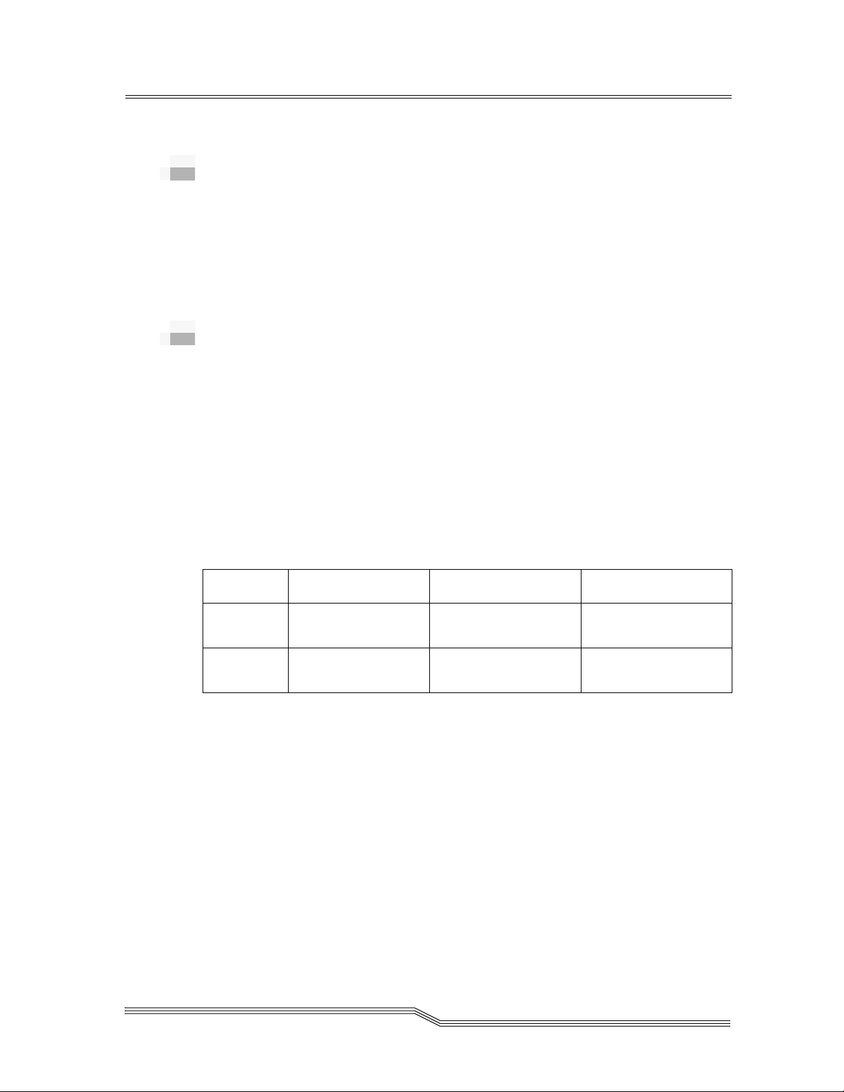
Table 2-1 Maximum Capacity
Model DLTTape III DLTTape IIIXT DLTTape IV
4000DLT 10 GB (native)
20 GB (compressed)
7000DLT 10 GB (native)
20 GB (compressed)
The 4000/7000DLT Series are equipped with a 5
factor, half-inch tape drive. The design includes a dualchannel read/write head, Digital Lempel-Ziv (DLZ) highefficiency data compression, and tape mark directory to
maximize data throughput and minimize data access time.
Used for unattended backups or archiving, the 4000/7000DLT
Series allows you to back up a higher data capacity at higher
speed than either 8mm or 4mm DAT-based drives. Table 2-2
lists the maximum compressed mode transfer rates of the two
models:
15 GB (native)
30 GB (compressed)
15 GB (native)
30 GB (compressed)
20 GB (native)
40 GB (compressed)
35 GB (native)
70 GB (compressed)
1/4
inch form
Overview 2-3
Page 18
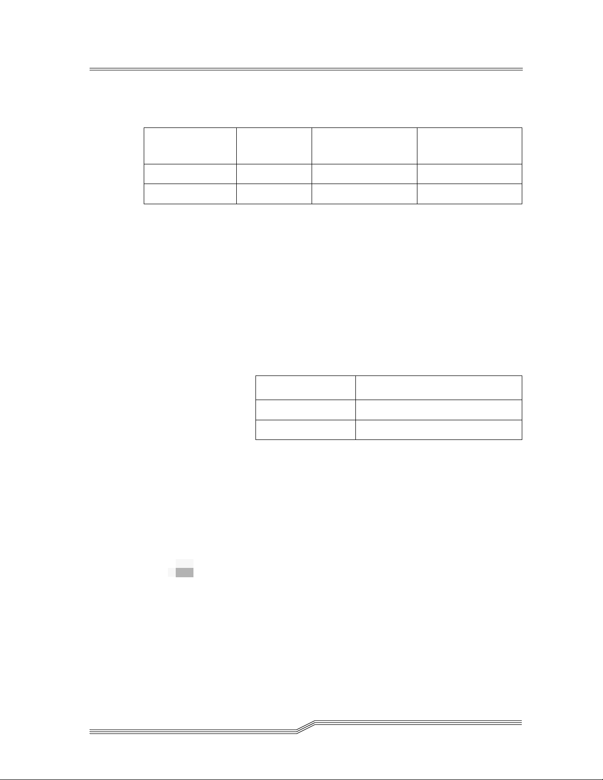
Table 2-2 Transfer Rate (Compressed Mode)
Model Sustained
4000DLT 3.0 MB/sec 3.0 MB/sec 3.5 MB/sec
7000DLT 10.0 MB/sec 10.0 MB/sec 10.0 MB/sec
The removable tape media cartridge allows long-term off-line
and/or off-site data storage. The tape media is rated at up to
500,000 passes and has a shelf life of up to 30 years providing
superior media durability and data reliability.
Table 2-3 on page 2-4 lists the drive models used in the
4000/7000DLT Series. Tape density is selected either from the
drive front panel or the host. The 4000DLT, and 7000DLT
drives can read/write 2.6, 6.0, and 10.0 GB formatted tapes for
100% interchange compatibility with earlier DLT drives.
Table 2-3 Drive to Model Identification
Model Drive Model
4000DLT DLT4000
Maximum
(Write Operation)
Maximum
(Read Operation)
7000DLT DLT7000
The 4000/7000DLT Series includes Flash EEPROM
technology that allows easy on-site installation of firmware
updates from tape or from the host.
The 4000/7000DLT Series includes embedded diagnostic
software that tells you when head cleaning is required,
diagnostic results, and drive operating status. The drive has
embedded data logging of errors for failure analysis.
Front Panel Controls and Indicators
Figure 2-1 on page 2-5, and Figure 2-2 on page 2-6 show the
controls and indicators located on the front panel of the
4000/7000DLT Series.
2-4 Description
62-0162-01
Page 19

Figure 2-1 7000DLT Front Panel
Description 2-5
Page 20
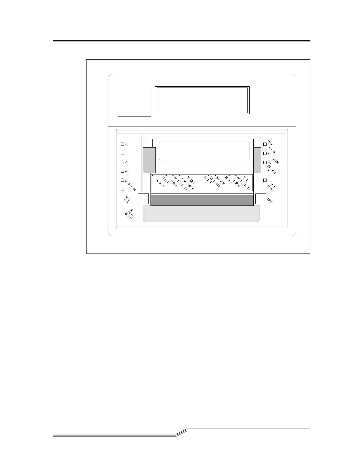
Figure 2-2 4000DLT Front Panel
2-6 Description
62-0162-01
Page 21
Table 2-4 Front Panel Indicators and Controls
2-line by 20-character
LCD Display
Beeper Sounds whenever it is OK to operate the cartridge insert/
Write Protected
(orange)
Tape in Use
(yellow)
Use Cleaning Tape
(yellow)
Operate Handle
(green)
Density Select 2.6
(yellow)
Density Select 6.0
(yellow)
Density Select 10.0
(yellow)
Density Select 20.0
(yellow) [4000DLT
only]
Density Select 70.0
(yellow) [7000DLT
only]
Compress
(yellow)
Density Override
(yellow)
Unload Button Pressing this button initiates a manual unload of the tape.
Cartridge Insert/
Release Handle
Displays drive status, error messages, POST results
release handle. The green Operate Handle LED should be
ON whenever the Beeper sounds.
ON = Tape write-protected.
OFF = Tape write enabled.
Blinking = Tape moving.
ON = Tape loaded; ready for use.
ON = Drive head needs cleaning, or the tape is bad.
OFF = cleaning complete, or cleaning unnecessary.
ON = OK to operate the cartridge insert/release handle.
OFF = Do not operate the cartridge insert/release handle.
ON = Tape is recorded in 2.6 GB format.
Blinking = Tape is recorded in another density.
ON = Tape is recorded in 6.0 GB format.
Blinking = Tape is recorded in another density.
ON = Tape is recorded in 10.0 GB format.
Blinking = Tape is recorded in another density.
ON = Tape is recorded in 20.0 GB format.
Blinking = Tape is recorded in another density.
ON = Tape is recorded in 70.0 GB format.
Blinking = Tape is recorded in another density
ON = Compression mode enabled.
OFF = Compression mode disabled.
ON = Density selected from front panel.
OFF (default) = Density selected from host.
Blinking = In density selection mode.
This may take from 10 seconds to 4 minutes depending on
tape position.
Lift this handle (only when the Operate Handle LED is ON,
and after the momentary beep sounds) to load or eject a
cartridge from the drive. The handle lifts to the open
position and lowers to the closed position.
Description 2-7
Page 22
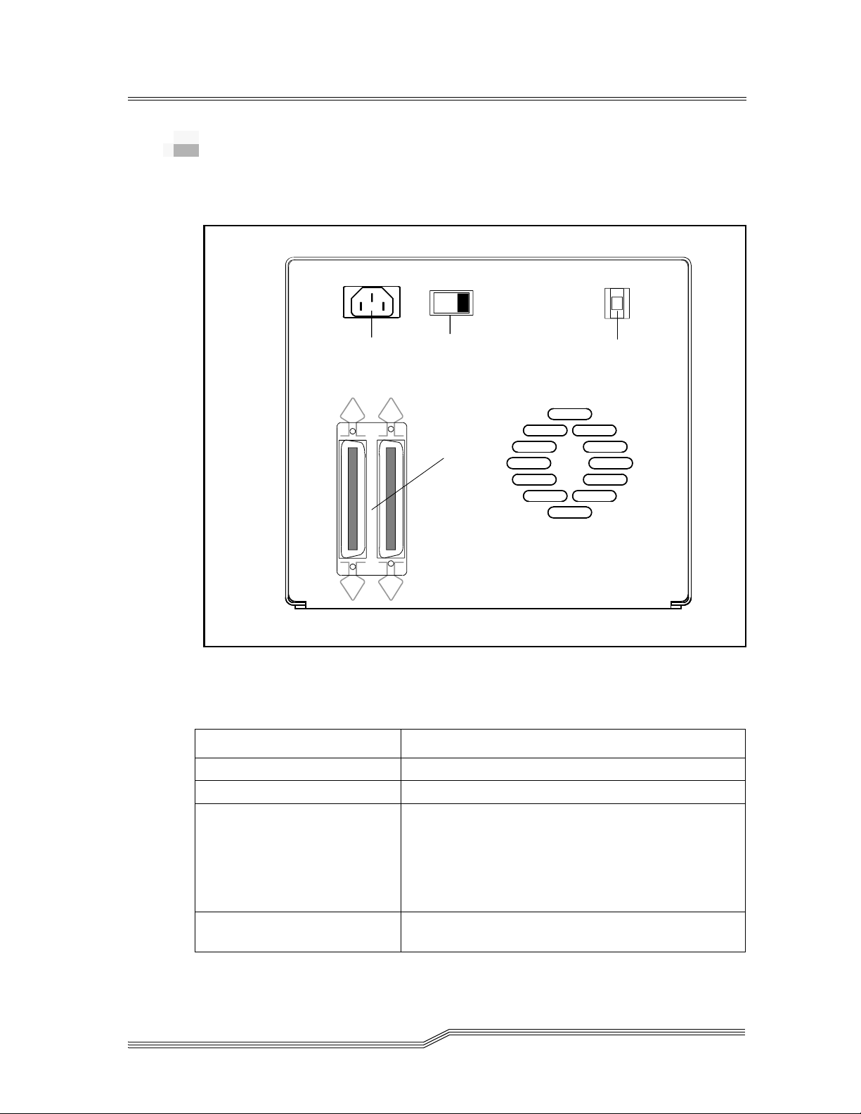
Rear Panel Controls and Connectors
Figure 2-3 on page 2-8 shows the controls and connectors
located on the rear panel of the 7000DLT Series.
3
AC Power
Connector
Power
Sw itc h
SCSI Channel
Connectors
Figure 2-3 7000DLT Series Rear Panel
Table 2-5 describes the controls and connections.
Table 2-5
Rear Panel Controls and Connectors
Control or Connector Purpose
SCSI ID
Switch
Power Switch Turns power to the unit on and off.
AC Power Connector Receptacle for AC power cord.
SCSI Channel Connectors Connections for the interface cable that connects the
SCSI ID Switch Used to select the SCSI ID for the DLT drive. Factory
2-8 Description
unit with the host computer and/or to other devices
on the SCSI channel. The interface cable can be
attached to either connector.
The 7000DLT, a fast, wide SCSI-2 device, uses a 68pin high density SCSI device connector.
set at 0.
62-0162-01
Page 23

Data Cartridge
The data cartridges used in the DTL7000 Series are housed in
4-inch plastic cases and employ 1/2-inch metal particle tape.
Table 2-6 describes and lists the media cartridges that can be
used with the four models.
Table 2-6
Model
4000DLT DLT4000 DLTTape III
7000DLT DLT7000 DLTTape III
Media Cartridge
Drive
Model
The Write-Protect
If the switch is moved all the way to the left, the cartridge is
write-protected and the drive cannot write to, or erase data
from, the cartridge. The small orange rectangle will be visible
whenever the cartridge is write-protected. Additionally, an
arrow (beneath the orange rectangle and above the two lines
on the switch), lets you know that data cannot be written to
the cartridge. If the switch is moved all the way to the right,
the cartridge is write-enabled and the drive can write data to,
or erase data from, the cartridge. The orange rectangle will not
be visible whenever the cartridge is write-enabled. On the
right side of the write-protect switch an arrow over one line
indicates that if you slide the switch to the right, data can be
written to the cartridge. Refer to Figure 2-4 on page 2-10.
Cartridge Model
DLTTape IIIXT
DLTTape IV
DLTTape IIIXT
DLTTape IV
Cartridge
Color
gray
white
black
gray
white
black
switch prevents accidental erasure of data.
Tape
Length
1100 feet
1800 feet
1800 feet
1100 feet
1800 feet
1800 feet
Description 2-9
Page 24
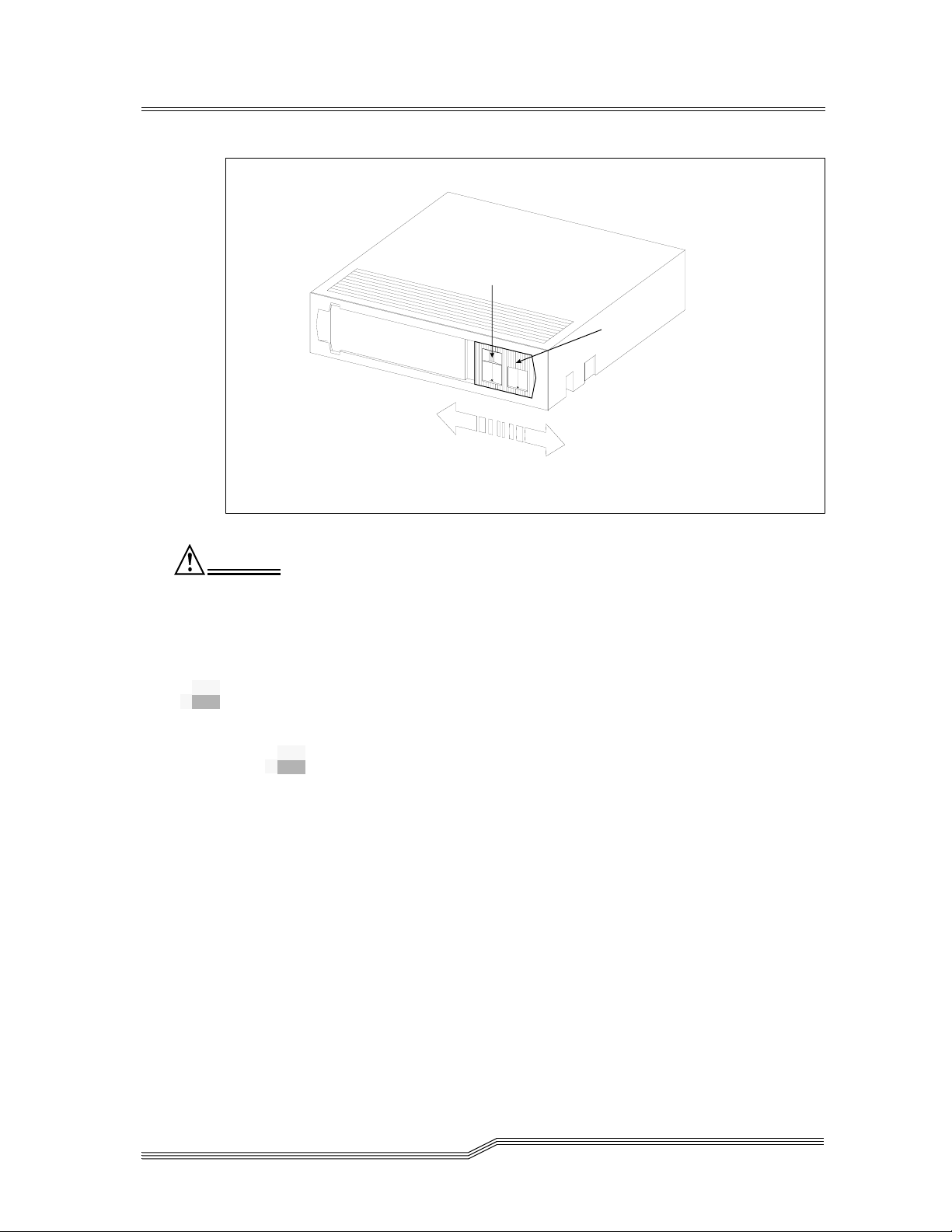
ORANGE
INDICATOR
WRITE-PROTECTED
Figure 2-4 DLT Data Cartridge
WRITE-PROTECT
SWITCH
WRITE-ENABLED
Caution
Always remove any cartridge from the drive before turning
off host system power. Failure to remove a cartridge can
result in cartridge and drive damage.
When you remove the cartridge from the drive, return the
cartridge to its plastic case to prolong the cartridge life.
Other Requirements
SCSI Host Adapter
If your host system does not have an integrated SCSI
controller, a SCSI host adapter must be used to connect the
host computer with the 7000DLT Series. The host adapter you
choose will depend on your system requirements and your
needs.
2-10 Description
62-0162-01
Page 25
SCSI Interface Cable
The kind of cable you need will depend on the kind of SCSI
bus connector on your host adapter. The 7000DLT, a fast, wide
SCSI-2 device, uses a 68-pin high density SCSI device
connector.
Application Software
The software you use will depend upon your storage needs
and the system you are using.
Additional Items
• At least one data cartridge. See Table 2-7.
Table 2-7 Cartridge Requirements
Model Required Cartridge
4000DLT DLTTape IV
7000DLT DLTTape IV
• A SCSI bus active terminator.
Other Requirements 2-11
Page 26

2-12 Description
62-0162-01
Page 27

3
Safety
Safety Conventions . . . . . . . . . . . . . . . . . . . . . . . . . . . . . . . . . . . . . . . . . . . . . . . . . . . . . . .3-3
Precautions . . . . . . . . . . . . . . . . . . . . . . . . . . . . . . . . . . . . . . . . . . . . . . . . . . . . . . . . . . . . . .3-4
Page 28

3-2 Safety
62-0162-01
Page 29

Safety Conventions
The following symbols are used throughout the document.
Table 3-1 Hazard Alert Messages
Symbol Damage to ... Signal Word Definition Consequence
3-
Persons
Material
Imminent hazardous
electrical situation
Potential damaging
situation
Caution
Tips for operators No hazardous or
Note
Important or useful
information
The danger exists of a fatal electric shock. At places
designated with this symbol, electrical current can be
present even after switching off the main switch. Before
starting any work, always confirm that all electrical
connections are free of electrical current.
Death or serious
injury
Possibly damage
to the product or
environment
damaging
consequences
No hazardous or
damaging
consequences
Caution
Note
This symbol means that specific regulations, rules, notices,
and working procedures must be observed. Ignoring this
symbol can lead to equipment damage or destruction or to
other property damage.
This symbol draws attention to user tips. No dangerous or
damaging consequences for personnel or property are
associated with this symbol.
This symbol indicates useful information. No dangerous or
damaging consequences for personnel or property are
associated with this symbol.
Safety Conventions 3-3
Page 30

All safety and operating instructions should be read before
this product is operated, and should be retained for future
reference. This unit has been engineered and manufactured
to assure your personal safety. Improper use can result in
potential electrical shock or fire hazards. In order not to
defeat the safeguards, observe the following basic rules for
its installation, use and servicing.
• Heed Warnings - All warnings on the product and in the
operating instructions should be adhered to.
• Follow Instructions - All operating and use instructions
should be followed.
• Power Sources - The product should be connected to a
power source only of the type directed in the operating
instructions or as marked on the product.
• Power Cord Protection - The AC line cord should be
routed so that it is not likely to be walked on or pinched
by items placed upon or against it, paying particular
attention to the cord at the wall receptacle, and the point
where the cord exits from the product.
• Power Switch - The power switch used in this product
does not disconnect both supply conductors when placed
in the OFF position. To completely disconnect power from
this product, unplug the AC power cord from the
receptacle on the back of the unit.
• Object and Liquid Entry - Care should be taken to insure
that objects do not fall and liquids are not spilled into the
product’s enclosure through openings.
• Servicing - The user should not attempt to service the
product beyond that described in the operating
instructions. All other servicing should be referred to
qualified service personnel.
3-4 Safety
Precautions
Do not use oil, solvents, gasoline, paint thinner or insecticides
on the unit.
Do not expose the unit to moisture, to temperatures higher
than 140ºF (60ºC) or to extreme low temperatures.
Keep the unit away from direct sunlight, strong magnetic
fields, excessive dust, humidity and electronic/electrical
equipment which generates electrical noise.
Hold the AC power plug by the head when removing it from
the AC source outlet; pulling the cord can damage the internal
wires.
62-0162-01
Page 31

Use the unit on a firm level surface free from vibration, and do
not place anything on top of unit.
Precautions 3-5
Page 32

3-6 Safety
62-0162-01
Page 33

4
Installation
Overview . . . . . . . . . . . . . . . . . . . . . . . . . . . . . . . . . . . . . . . . . . . . . . . . . . . . . . . . . . . . . . . 4-3
Unpacking and Inspecting . . . . . . . . . . . . . . . . . . . . . . . . . . . . . . . . . . . . . . . . . . . . . . . . .4-3
Installing the Host Adapter . . . . . . . . . . . . . . . . . . . . . . . . . . . . . . . . . . . . . . . . . . . . . . . .4-3
Connecting the Interface Cable . . . . . . . . . . . . . . . . . . . . . . . . . . . . . . . . . . . . . . . . . . . . .4-3
Connecting More than One 4000/7000DLT Series . . . . . . . . . . . . . . . . . . . . . . . . . 4-4
Setting the SCSI ID . . . . . . . . . . . . . . . . . . . . . . . . . . . . . . . . . . . . . . . . . . . . . . . . . . . . . . .4-5
Check the SCSI Bus Termination . . . . . . . . . . . . . . . . . . . . . . . . . . . . . . . . . . . . . . . . . . .4-6
Connecting Power and Turning On . . . . . . . . . . . . . . . . . . . . . . . . . . . . . . . . . . . . . . . . .4-7
Installing the Backup Software . . . . . . . . . . . . . . . . . . . . . . . . . . . . . . . . . . . . . . . . . . . . .4-7
Page 34

4-2 Installation
62-0162-01
Page 35

Overview
This chapter explains the steps necessary to install and test
your 4000/7000DLT Series. It also provides an information
symbol for each event that you should verify as correct before
continuing.
Unpacking and Inspecting
Unpack all items from the carton.
None of the components should have any damage.
Save the packing materials in case you need to move or ship
the system in the future. You must ship the unit in the
original or equivalent packing materials or your warranty
may be invalidated.
4-
Installing the Host Adapter
Connecting the Interface Cable
Note
The bail (or other)
locks at the ends
of the SCSI cable
must be securely
fastened to insure
communications
between the
4000/7000DLT
Series and the
host computer.
If your host computer does not have native SCSI capability
and the host adapter you are using is not installed, please
install it. Refer to the manual that came with your host adapter
for specific directions.
Attach an interface cable between the host adapter and your
4000/7000DLT Series. The kind of cable you need depends on
the kind of SCSI bus connector on your host adapter. The
4000/7000DLT Series has two SCSI device connectors on the
rear panel. It does not matter which connector you use.
Make sure that the SCSI cable between the host adapter and
the 4000/7000DLT Series is secure and the connections are
fastened correctly.
Overview 4-3
Page 36

p
y
Connecting More than One 4000/
7000DLT Series
Note
Don’t forget to
install the SCSI
terminator on the
last device in the
chain.
If you are connecting more than one 4000/7000DLT Series
unit on the same SCSI channel, simply connect each unit to the
previous unit with an additional interface cable. It doesn't
matter which SCSI connector on each 4000/7000DLT Series
unit you connect the interface cable to. Figure 4-1 shows a
sample configuration.
4DS9X00Units
Dais
SCSI
Interfac e Cab les
Chained
Terminato
r
SCSI ID 3
SCSI ID 2
Figure 4-1 Cable Diagram for 4 4000/7000DLT Series Units
4-4 Installation
Host Com
SCSI ID 1
uter
SCSI ID 0
62-0162-01
Page 37

Setting the SCSI ID
Note
The SCSI ID has
been factory
preset to 0.
All devices on a
SCSI bus must be
set to a unique
address.
Depending upon your setup, operating system and number of
SCSI devices on the bus, you may have to change the SCSI
address of the 4000/7000DLT Series. Each device on the bus
must have its own unique address. See Figure 4-1 on page 4-4
and Figure 4-2.
3
SCSI ID
Switch
Figure 4-2 SCSI ID Switch
Note
All
4000/7000DLT
Series models can
be set to any SCSI
ID between 0 and
7. The 7000DLT, a
fast-wide SCSI-2
device, can be set
to any SCSI ID
between 0 and 15.
The SCSI ID switch is located on the rear of the 4000/7000DLT
Series (see Figure 7). Use a small pointed object to press either
the + button on the bottom, or the minus button on the top of
the switch to select the proper ID.
Setting the SCSI ID 4-5
Page 38

Note
The SCSI Host
Adapter is
normally set to
SCSI ID 7, so this
ID is usually not
available for a
device.
Check the SCSI Bus Termination
Count each device's SCSI ID in sequence 0 to 7 (or 0 to 15),
on each SCSI bus to confirm that no two devices have the
same ID.
SCSI buses require termination at each end for proper
operation. A typical external subsystem installation would be
terminated at the SCSI host adapter and at the last device in
the chain.
If an external device is being used with an internal device (on
the same channel), the SCSI host adapter would now be in the
middle of the bus rather than at the end. In this case, the
termination would be at the internal device and the last drive
in the external chain. The terminators on the SCSI host
adapter would be removed. See your SCSI host adapter
manual for directions on removing the terminators on the
board.
Note
For single-ended
drives,
recommends
using an active
single-ended
SCSI terminator.
For differential
drives, use a
passive
differential
terminator.
Is there a terminator installed on each end of the SCSI bus?
4-6 Installation
62-0162-01
Page 39

Connecting Power and Turning On
Step 1 Plug the power cord into the back of the 4000/
7000DLT Series.
Step 2 Plug the power cord from the 4000/7000DLT Series
into a GROUNDED electrical outlet.
Step 3 Plug the power cord from your host system into the
same GROUNDED electrical circuit if possible.
Computers and peripherals should always share
the same grounds.
Step 4 Turn ON the power to your host system.
Note
Turning on the
host computer
first ensures that
the SCSI bus
terminators
stabilize the bus
signals before the
tape drive is
turned on.
Installing the Backup Software
Step 5 Turn the 4000/7000DLT Series power ON.
At this point, please refer to your backup software installation
guide and install the backup software.
After you have completed installation of your 4000/7000DLT
Series and the backup software, you should run a small
backup/restore and compare to confirm that your unit is
working correctly. See your software installation guide for
additional information.
Connecting Power and Turning On 4-7
Page 40

4-8 Installation
62-0162-01
Page 41

5
Operation and
Maintenance
Overview . . . . . . . . . . . . . . . . . . . . . . . . . . . . . . . . . . . . . . . . . . . . . . . . . . . . . . . . . . . . . . . 5-3
Power-on Self-Test . . . . . . . . . . . . . . . . . . . . . . . . . . . . . . . . . . . . . . . . . . . . . . . . . . . . . . .5-3
Drive Status . . . . . . . . . . . . . . . . . . . . . . . . . . . . . . . . . . . . . . . . . . . . . . . . . . . . . . . . . . . . . 5-4
LED Indicators . . . . . . . . . . . . . . . . . . . . . . . . . . . . . . . . . . . . . . . . . . . . . . . . . . . . . . .5-4
LCD Messages . . . . . . . . . . . . . . . . . . . . . . . . . . . . . . . . . . . . . . . . . . . . . . . . . . . . . . .5-5
Drive Operating Conditions . . . . . . . . . . . . . . . . . . . . . . . . . . . . . . . . . . . . . . . . . . . . . . .5-6
LED Indicators . . . . . . . . . . . . . . . . . . . . . . . . . . . . . . . . . . . . . . . . . . . . . . . . . . . . . . .5-6
LCD Messages . . . . . . . . . . . . . . . . . . . . . . . . . . . . . . . . . . . . . . . . . . . . . . . . . . . . . . .5-8
Loading the Data Cartridge . . . . . . . . . . . . . . . . . . . . . . . . . . . . . . . . . . . . . . . . . . . . . . .5-12
Data Protection . . . . . . . . . . . . . . . . . . . . . . . . . . . . . . . . . . . . . . . . . . . . . . . . . . . . . . . . . 5-13
Tape in Use . . . . . . . . . . . . . . . . . . . . . . . . . . . . . . . . . . . . . . . . . . . . . . . . . . . . . . . . . . . . .5-13
Removing the Data Cartridge . . . . . . . . . . . . . . . . . . . . . . . . . . . . . . . . . . . . . . . . . . . . .5-14
Cleaning the Tape Head . . . . . . . . . . . . . . . . . . . . . . . . . . . . . . . . . . . . . . . . . . . . . . . . . .5-15
Cleaning the Enclosure . . . . . . . . . . . . . . . . . . . . . . . . . . . . . . . . . . . . . . . . . . . . . . . . . . .5-18
Page 42

5-2 Operation and Maintenance
62-0162-01
Page 43

Overview
p
p
This section describes normal operating features of the
4000/7000DLT Series. Additionally, it explains how, and
when, to clean the tape head. This section also describes how
to clean the enclosure.
Power-on Self-Test
When you turn system power ON, the DLT drive performs a
Power-on Self-Test (POST). The sequence of events is:
• The LEDs on the right front panel of the DLT drive will
turn on sequentially from top to bottom. All LEDs will
remain ON for a few seconds.
• The LEDs on the left front panel will turn ON at the same
time for about three seconds and then turn
•The
Ta
blink while the tape drive initializes.
• If your external SCSI bus terminator has a Term Power
LED it should also be illuminated.
erate Handle Write Protected
O
LEDs will turn
e
OFF
. The
and
Use Cleaning
Tape in Use
OFF
.
LED will
5-
Overview 5-3
Page 44

Drive Status
p
p
p
y
p
LED Indicators
After initialization, the drive will be in one of the four states
listed in Table 5-1.
Table 5-1 Drive States Indications
Drive State LED Indicator Displays and Drive Actions
No cartridge is present. The
The
The handle is unlatched.
The drive beeps momentarily.
A cartridge is present and
the handle is down.
A cartridge is present, but
the handle is up (not
recommended).
The drive detects an error
condition.
The drive loads the cartridge.
When the
ON, the tape’s actual density lights. For example, if
the actual tape density is 2.6, then the LED turns ON
next to the 2.6 label.
When the
select a density. The drive is ready for use.
The
Handle
When you lower the handle, the cartridge loads.
Then all right or left side LEDs blink repeatedly.
You may try to unload the tape (if present) and
reinitialize the drive by pressing the
or turn power OFF and then ON again. The right or
left side LEDs stop blinking and the drive tries to
reinitialize. The LEDs turn ON steadily again and
then turn OFF if the test succeeds.
e in Use
Ta
erate Handle
O
Ta
Densit
Ta
e in Use
LED flashes.
LED turns OFF.
LED turns ON.
e in Use
LED stops blinking and stays
Override
LED turns OFF. The
LED blinks, you can
Operate
Unload
button
5-4 Operation and Maintenance
62-0162-01
Page 45

LCD Messages
Table 5-2 describes the messages displayed on the LCD
during and immediately after the POST.
Table 5-2 Drive Status LCD Messages
Drive State LCD Message
POST is executing.
Will be displayed for 3 to 5 seconds, followed by:
DRV F/W is the firmware version of the drive.
LCD F/W is the firmware version of the LCD controller.
ID is the SCSI ID setting of the drive.
CPH is the cululative power on hours of the drive.
TSL us the time since last cleaning cycle of the drive (resets
to zero after every cleaning cycle if powered by a power
cycle).
DCL is the drive data cartridge load counter.
POST completed, no cartridge is
present, and the handle is down.
Note
This is the
4000/7000DLT when powering up.
preferred
state for the
or ‘4000DLT’ (DLT4000)
POST completed, a cartridge is
present, but the handle is up
(
not recommended
Note
The 4000/7000DLT
left in this state when powering
down.
The drive detects an error
condition.
).
should not
This message will appear after approximately 5 minutes.
be
POST completes in about 13 seconds and the drive responds normally to all
commands. However, it may take longer for the media to become ready.
Drive Status 5-5
Page 46

POST completes in about 13 seconds and the drive responds normally to all ommands.
However, it may take longer for the media to become ready.
Drive Operating Conditions
LED Indicators
Use Table 5-3 on page 5-6 to determine the drive’s operating
condition.
Table 5-3 Operating Condition Indications
Right Indicator Panel LED
Label Color State Operating Condition
Write Protected Orange ON
OFF
Tape in Use Yellow Blinking
ON
Use Cleaning Tape Yellow ON
Remains on
after unloading
cleaning tape
After cleaning,
turns on again
when reloading
data cartridge
Operate Handle Green ON
OFF
Blinking
All Right Indicator
Panel LEDs or,
All Left Indicator
Panel LEDs
-ON
Blinking
Tape is write-protected.
Tape is write-enabled.
Tape is moving.
Tape is loaded; ready for use.
Drive head needs cleaning,
or the tape is bad.
Cleaning attempted, but tape
expired, so cleaning not
performed.
Problem data cartridge. Try
another cartridge.
OK to operate the Cartridge
Insert/Release Handle.
Do not operate the Cartridge
Insert/Release Handle.
Drive was powered on with
door open. Close door and
let drive complete
initialization.
POST is starting.
An error has occurred.
5-6 Operation and Maintenance
62-0162-01
Page 47

Table 5-3 Operating Condition Indications
Left Indicator Panel LED
Label Color State Operating Condition
2.6 Yellow ON
Blinking
6.0 Yellow ON
Blinking
10.0 Yellow ON (default)
Blinking
20.0 (4000/7000DLT) Yellow ON (default)
Blinking
Compress Yellow ON
OFF
Tape is recorded in 2.6
format.
Tape is recorded in another
density. You selected this
density for a write from BOT.
Tape is recorded in 6.0
format.
Tape is recorded in another
density. You selected this
density for a write from BOT.
Tape is recorded in 10.0
format.
Tape is recorded in another
density. You selected this
density for a write from BOT.
Tape is recorded in 20.0
format.
Tape is recorded in another
density. You selected this
density for a write from BOT.
Compression mode enabled.
(Compression can be done
only in 10.0, 15.0, 20.0, and
70.0 density.)
Compression mode disabled.
Density Override Yellow ON
OFF (default)
Blinking
All Right Indicator
- Blinking A POST error has occurred.
Panel LEDs, or,
all Left Indicator
Panel LEDs
You selected a density from
the front panel.
Density will be selected by
the host (automatic).
You are in density selection
mode.
Drive Operating Conditions 5-7
Page 48

LCD Messages
Table 5-4 on page 5-8 describes the messages displayed by the
LCD during normal operation:
Table 5-4 Drive Operation LCD Messages
Drive Operating
Condition
No tape in drive.
When loading or unloading
a tape.
LCD Message
or, ‘4000DLT’ (DLT4000)
DLTtype = DLT4000 (4000DLT), or DLT7000
(7000DLT).
During the loading process the display may toggle
between “Loading >>>” and “Calibrating>>>”.
Note
While loading the tape, the drive
will enter a false Ready Mode
condition for a short period. During
this false state the Tape In Use LED
will continue to blink. Do not
attempt any operations while the
LED is blinking.
When tape is unloaded.
5-8 Operation and Maintenance
62-0162-01
Page 49

Table 5-4 Drive Operation LCD Messages
When tape is loaded.
If write-protected tape is
inserted
Write-protected tape fully
loaded.
DLTtype = DLT
TM
4000 (4000DLT), or DLTTM7000
(7000DLT).
Compressed if compression mode enabled or
Standard if compression mode disabled.
TM
20/40GB = DLT
4000, 35/70GB = DLTTM7000.
This is the normal “Ready Screen”.
During loading of a write-protected tape, the display
will change from:
“Loading>>>” to “Write Protected Tape Inside
Drive”, the LCD backlight will toggle on/off and an
audible alarm will sound.
WPT = Write Protected Tape in unit.
WPT will toggle to GB and back to WPT and
continue toggling until next drive action.
Drive Operating Conditions 5-9
Page 50

Table 5-4 Drive Operation LCD Messages
Whenever the system is
writing to a tape, these two
messages will alternate.
Each message will be
displayed for
approximately 2.5 seconds.
Whenever the system is
reading a tape, this
message will alternate with
the ready screen.
Whenever a tape is in
motion.
DLTtype = DLT
TM
4000 (4000DLT), or DLTTM7000
(7000DLT).
Compressed if compression mode enabled, standar d
if compression mode disabled.
Writing – indicates the system is writing to the tape.
2.1:1 – indicates the current compression ratio being
used.
16GB – indicates the amount of tape still available to
be written to.
3 arrows in motion ( ) – indicate tape travel.
Reading – indicates the system is reading from the
tape.
Motion Messages = Loading, Unloading, Reading,
Writing, Positioning, Erasing, Cleaning and
Rewinding.
3 arrows ( ) – indicate tape travel.
Whenever an incorrect
cartridge type is placed into
a drive.
5-10 Operation and Maintenance
The LCD will flash and the beeper will sound while
this message is displayed.
Press the Unload button, the drive will begin
unloading the tape and the LCD will return to
normal operation messages.
62-0162-01
Page 51

Table 5-4 Drive Operation LCD Messages
The drive head needs
cleaning or the tape is bad.
followed by:
If new tape, or the drive
cannot initialize the tape.
followed by:
followed by:
A hardware error occurs
during normal operation.
Drive Operating Conditions 5-11
Page 52

Loading the Data Cartridge
p
g
g
Caution
Caution
Due to static the label or other items included in this
package will occasionally cling to the DLT cartridge.
Before loading into a drive, ensure that all other items from
this package are separated from the cartridge.
Never press in on the hub portion of the data cartridge.
Step 1 If you are planning to write data to, or erase data
from, the cartridge, make sure the
on the cartridge is in the write-enabled position (all
the way to the right).
A data cartridge can only be loaded when the
Handle
Insert/Release Handle
Step 2 Lift up on the
LED is ON. Do not attempt to open the
unless this LED is ON steady.
Cartrid
e Insert/Release Handle
Write-Protect
O
erate
Cartrid
switch
e
.
Figure 5-1 Loading a Data Cartridge
5-12 Operation and Maintenance
62-0162-01
Page 53

Step 3 Insert the data cartridge into the slot.
Step 4 Push the cartridge into the drive.
Step 5 Push the Cartridge Insert/Release Handle closed
A load sequence will initiate where the Operate Handle
LED will turn OFF and the Tape in Use LED will blink
while the drive moves the tape to BOT (Beginning of Tape).
When the tape is at BOT, the Tape in Use LED will turn ON
steady. Additionally, one of the compression density LEDs
on the Left Indicator Panel may be illuminated or blinking.
The tape is now ready for use.
Data Protection
Caution
The Write-Protect switch on the data cartridge can be
moved while the cartridge is loaded into the drive. The drive
will turn on the Write-Protect LED immediately. However,
if the drive is writing to the tape, write protect does not take
effect until the write operation completes.
Before loading the data cartridge, if you move the
Write-Protect switch to the left, the tape is write-protected;
the Write Protected LED (orange) is ON and data cannot be
written to, or erased from, the tape.
.
The drive will go on-line.
Tape in Use
Before loading the data cartridge, if you move the
Write-Protect switch to the right, the tape is write-enabled
and data can be written to, or erased from, the tape (if it is not
software write-protected).
After loading the data cartridge and during operation, if you
move the Write-Protect switch from the write-protected
position (to the left) to the write-enabled position (to the
right), the tape becomes write-enabled after a variable amount
of time (seconds).
After loading the data cartridge and during operation, if you
move the Write-Protect switch from the write-enabled
position (to the right) to the write-protected position (to the
left), the tape becomes write-protected after a variable amount
of time (seconds).
Whenever the Tape in Use LED (yellow) is ON steady, the
tape is ready to use. When the tape is being read, written, or
rewound, Tape in Use blinks.
Data Protection 5-13
Page 54

Table 5-5 indicates what is happening during cartridge use:
p
p
g
p
g
Table 5-5
LED State Meaning
Tape in Use ON steady
Operate
Handle
All LEDs Blinking An error has occurred during operation.
Tape in Use Indications
(Right Indicator Panel)
Blinks irregularly
Blinks regularly
ON and beeper
sounds
A cartridge is loaded, but the tape is not
moving. This can mean no application is
communicating with the controller, or that
the application is communicating but is not
delivering commands for tape motion.
A read or write is in progress.
Tape is loading, unloading, or rewinding.
Tape is unloaded into the cartridge and the
cartridge can now be removed, or if the
drive is unloaded, a cartridge can now be
inserted.
Removing the Data Cartridge
Caution
Remove a cartridge from the drive before turning OFF host
system power. Failure to remove a cartridge before turning
OFF host system power can result in cartridge and drive
damage.
Caution
5-14 Operation and Maintenance
To unload a cartridge from the drive perform the following
steps
Step 1 Push the
The
A data cartridge can only be unloaded when the
Handle
Insert/Release Handle
Step 2 When the
Step 3 Remove the cartridge.
e in Use
Ta
LED is ON. Do not attempt to open the
beeper has sounded), pull the
Insert/Release Handle
from the drive.
Unload
LED will blink as the tape rewinds.
O
62-0162-01
button.
O
Cartrid
unless this LED is ON steady.
erate Handle
LED is ON (and the
Cartrid
open to eject the cartridge
e
erate
e
Page 55

Step 4 Push the Cartridge Insert/Release Handle closed.
Caution
When you remove the cartridge from the drive, return the
cartridge to its plastic case to prolong the cartridge life.
Cleaning the Tape Head
The 4000/7000DLT Series is a highly sophisticated unit. No
routine maintenance is required apart from periodically
cleaning the drive head whenever the Use Cleaning Tape
LED is illuminated and the LCD displays the following
message:
followed by
If your 4000/7000DLT Series fails to operate correctly,
immediately call the customer service.
Cleaning the head should always be performed as the first
step if the Use Cleaning Tape LED illuminates and the LCD
displays the above message.
Table 5-6 on page 5-16 tells you when to use the cleaning tape.
Cleaning the Tape Head 5-15
Page 56

Table 5-6 Using the Cleaning Tape
g
g
g
g
If . . . It means . . . You should . . .
While using a data
cartridge, the
Cleanin
Use
Tape
LED
illuminates and the front
panel LCD displays:
and:
While using a data
cartridge, the
Cleanin
Tape
Use
LED
begins to blink and the
front panel LCD
displays:
and
The drive head needs
cleaning or the tape is
bad
The data cartridge may
be damaged
Use the cleaning cartridge.
Load the cleaning
cartridge according to
Loading the Data Cartridge
on page 5-12.
When cleaning is
complete, the beeper will
sound alerting you to
remove the cleaning
cartridge. Remove the
cleaning cartridge from the
drive according to
Removing the Data Cartridge
on page 5-14
Back up the data from this
cartridge onto another
cartridge, it may be
damaged. A damaged
cartridge may cause
unnecessary use of the
cleaning cartridge.
Use Cleanin
Tape
LED
still illuminates after you
Your data cartridge may
be causing the problem
Try another data cartridge.
clean the drive head.
Use Cleanin
Tape
illuminates after you
load the cleaning
cartridge
LED
Cleaning has not been
accomplished and the
cleaning cartridge has no
remaining cycles
Replace the cleaning
cartridge.
available.
Caution
Using cloth swabs, cotton swabs, cleaning agents, or
unapproved cleaning cartridges will void your warranty.
Use only an approved cleaning cartridge.
5-16 Operation and Maintenance
62-0162-01
Page 57

To clean the head, use a cleaning cartridge. Inert the cleaning
cartridge in the drive as described in
on page 5-12. The drive will automatically clean the head.
When the cleaning operation is complete, the beeper will
sound alerting you to remove the cleaning cartridge. The
following messages will be displayed during the cleaning
process.
Table 5-7 Cleaning Cycle LCD Messages
When tape is loaded.
DLTtype = DLT
(7000DLT).
Compressed if compression mode enabled or
Standard if compression mode disabled.
20/40GB = DLT4000, 35/70GB = DLT7000.
This is the normal “Ready Screen”.
While loading the cleaning
tape.
Loading the Data Cartridge
TM
4000 (4000DLT), or DLTTM7000
While the cleaning cycle is
executing.
When cleaning cycle is
completed.
TM
DLTtype = DLT
4000 (4000DLT), or DLTTM7000
(7000DLT).
When the cleaning process is complete, the LCD will
display the following for 3 to 5 seconds:
CCL ia the Cleaning Cartridge Load Counter and
equals the number of timews that6 a cleaning
cartridge has been loaded in this drive.
CCA is the cumulative number of times this cleaning
cartridge has been used to clean a drive.
Cleaning the Tape Head 5-17
Page 58

Table 5-7 Cleaning Cycle LCD Messages
When cleaning tape is
unloaded.
Caution
Do not remove the cleaning cartridge before the drive
sounds the beeper.
Remove the cleaning cartridge from the drive as described in
Removing the Data Cartridge
If you load the cleaning cartridge into the drive after it has
exhausted its cleaning cycles, it will not clean the head (the
cycle is noticeably shorter) and the Use Cleaning Tape LED
will be illuminated. Be sure to replace the cleaning cartridge
when the cleaning cycle is noticeably shorter.
Cleaning the Enclosure
The outside of the enclosure can be cleaned with a damp
towel. If you use a liquid all-purpose cleaner, apply it to the
towel. Do not spray the enclosure.
on page 5-14.
5-18 Operation and Maintenance
62-0162-01
Page 59

6
Troubleshooting
and Diagnostic
Overview . . . . . . . . . . . . . . . . . . . . . . . . . . . . . . . . . . . . . . . . . . . . . . . . . . . . . . . . . . . . . . . 7-3
Troubleshooting Chart . . . . . . . . . . . . . . . . . . . . . . . . . . . . . . . . . . . . . . . . . . . . . . . . . . . . 7-3
Use Cleaning Tape LED . . . . . . . . . . . . . . . . . . . . . . . . . . . . . . . . . . . . . . . . . . . . . . . . . . .7-5
Why the Use Cleaning Tape LED Gets Turned ON . . . . . . . . . . . . . . . . . . . . . . . .7-6
High Humidity . . . . . . . . . . . . . . . . . . . . . . . . . . . . . . . . . . . . . . . . . . . . . . . . . . . . . . . . . . 7-7
Page 60

6-2 Troubleshooting and Diagnostic
62-0162-01
Page 61

Overview
This section lists a number of common problems and the
actions to take to correct them. It provides information on why
the DLT drive turns on the Use Cleaning Tape LED. The
section also explains what to do when you need technical
support.
Troubleshooting Chart
If the 4000/7000DLT Series fails during POST or operation,
use the following table to determine the problem and the
action to take:
Table 6-1 Problem Chart
If . . . Then . . . You should . . .
6-
Your system does not
recognize the
4000/7000DLT Series unit
Your system might not be
configured to see the
SCSI ID
The SCSI ID might not be
unique
The parameters for your
SCSI adapter may be
incorrect
The SCSI signal cable
may be loose
The SCSI terminator may
not be present or might
be loose
Configure your system to
see the ID.
Change the SCSI ID and
reconfigure the system.
The new ID is effective at
the next power-on.
Check your SCSI adapter
installation.
Make sure the connector on
each end of the cable is
fully seated and the bail
locks are secure.
Install the terminator;
make sure the terminator is
fully seated and the bail
locks are secure.
Overview 6-3
Page 62

Table 6-1 Problem Chart
Your system does not
recognize the
4000/7000DL T Series unit
(Continued)
The SCSI bus may not be
correctly terminated
The SCSI terminator may
not be at the end of the
bus, or more than two
terminators may be
present
The SCSI bus might be
too long.
Too many devices might
be on the bus
If the 4000/7000DLT Series
unit is the last or only
device on the bus, make
sure the terminator is
installed on the
4000/7000DLT.
If the 4000/7000DLT Series
unit is not the last or only
device on the bus, check
the cable connections and
make sure the terminator is
installed at the end of the
bus.
Be sure to install a
terminator at each end of
the bus. One terminator is
usually installed at the host
system.
Limit the bus length to the
ANSI SCSI-2 standard of 6
meters (19 feet) for single
ended buses [3 meters for
the 7000DLT].
Limit the number of
devices on the bus
(including the host system)
to eight.
The 4000/7000DL T Series
unit does not power up
6-4 Troubleshooting and Diagnostic
The 4000/7000DL T Series
unit has no power
62-0162-01
Check your system
configuration rules.
Check the 4000/7000 Series
unit power cord
connections with the 4000/
7000DLT Series unit power
switch OFF.
Page 63

g
g
g
g
Table 6-1 Problem Chart
All right or all left
indicator panel LEDs on
the drive front panel
blink
You are finding fatal or
nonfatal errors for which
you cannot determine the
cause
A drive fault has
occurred
The bus termination or
SCSI signal cable
connections might be
incorrect
The AC power source
grounding might be
incorrect
Try to unload the tape and
reinitialize the drive by
pressing the Unload button
or turn the 4000/7000DLT
Series unit power off and
then on again.
The LEDs will stop
blinking and the drive will
try to reinitialize. The LEDs
will turn on steady again
and go off if the test
succeeds.
Make sure the SCSI bus is
terminated.
Use an AC outlet for the
4000/7000 Series unit on
the same AC circuit as the
AC line powering the host
system.
Use Cleaning Tape LED
If an excessive number of read-after-write errors are detected
during normal operation of the 4000/7000DLT Series, the
Cleanin
Usually, the
drive because of a dirty head, so the head should be cleaned
and the operation tried again.
If the
Use Cleanin
seems to be a cartridge rather than a drive problem, make sure
that all the data on that cartridge is backed up to a new
cartridge by doing a complete backup from the source drive,
if necessary. Then discard the old cartridge. If you are unsure
of the problem source, call customer service
The
Use Cleanin
executing a cleaning cycle or by cycling power to the
4000/7000DLT Series.
LED will be turned on by the drive.
Tape
Use Cleanin
Tape
Tape
LED is turned on by the
Tape
LED is again turned on and this
.
LED is normally turned off by
Use
Use Cleaning Tape LED 6-5
Page 64

g
g
Why the Use Cleaning Tape LED Gets
Turned ON
The
Use Cleanin
drive has determined that low level error performance has
degraded to a point where drive head cleaning is absolutely
required. It does this by counting the number of C3 (soft)
errors as well as the RAW (Read After Write) errors over a
number of Mbytes. When a predetermined error rate
threshold is reached, the drive displays the warning. Some
drives display the warning after a specified number of hours
of tape motion have been logged. When a tape is loaded, it
may take several minutes for the indication to come on
because the drive will wait for a specific number of bytes to be
written. A hard (non-recoverable) error will cause the
warning to be displayed immediately.
The most common reasons that the
gets turned on for, in order of highest rate of occurrence, are
listed below:
• Dirty ("Stained") heads.
A cleaning cycle must be executed to clear this indication.
• Worn tape.
DLT tapes are rated at 500,000 passes. Applications that
overwrite small blocks of data cause "shoe shining" of the
tape against the head and will reach the 500,000 passes
sooner than might be expected.
• Bad environment.
Data errors result from a number of factors, each of which
subtract from the margin between good data recovery
and an error. Electrical or magnetic interference can
decrease this margin. High levels of dust contamination,
high humidity, and heat can also be significant factors.
LED will be turned on whenever the
Tape
Use Cleanin
Tape
LED
6-6 Troubleshooting and Diagnostic
Placing a CRT monitor on top of, or directly next to, a
4000/7000DLT Series should always be avoided.
• Worn heads.
The tape heads will eventually wear out causing the time
between cleanings to get shorter and shorter. Tape head
failure is usually predicted at about 12% of the MTBF
rating (10,000 hours).
• Defective drive.
Drive amplifier settings could be off, causing error rate
degradation. The drive could simply have failed.
62-0162-01
Page 65

High Humidity
To minimize the chance of condensation, please observe the
following guidelines:
• If you expose cartridges to temperatures outside the
operating limits (5-40°C/40-113°F), stabilize them before
you use them. To do this, leave the cartridges in the
operating temperature for a minimum of two hours.
• Avoid temperature problems by ensuring that the
ventilator slots at the front of the drive and the grille on
the bottom of the chassis are not obstructed so that the
drive has adequate ventilation
• Position the drive where the temperature is relatively
stable, for example, away from open windows, fan
heaters, and doors.
• Avoid leaving cartridges in severe temperature
conditions, for example, in a car standing in bright
sunlight.
• Avoid transferring data (reading from and writing to
cartridges) when the temperature is changing by more
than 10°C per hour.
High Humidity 6-7
Page 66

6-8 Troubleshooting and Diagnostic
62-0162-01
Page 67

A
Specification
General Specification . . . . . . . . . . . . . . . . . . . . . . . . . . . . . . . . . . . . . . . . . . . . . . . . . . . . A-3
Page 68

A-2 Specification
62-0162-01
Page 69

Drive
General Specification
This section contains specification information on the
4000/7000DLT Series. See Table A-1.
Table A-1 Specifications
®
Type: Quantum
Quantum
DLT™4000
®
DLT™7000
A-
4000DLT
7000DLT
Enclosure
Reliability
Physical
Environment
Data Transfer Rate
(compressed mode):
Electrical Interface: SCSI-2
Physical Interface 50-pin, shielded, low-density device connector
Maintenance Periodic cleaning of drive head using DLT cleaning
MTBF: More than 80,000 power-on hours
MTTR: W ithin 30 minutes (drive replacement)
Dimensions: 5.75"(h) x 10.50" (w) x 14.50" (d)
Weight: 14 lbs.
180 MB/min.
600 MB/min.
SCSI-2 Fast, Wide
68-pin, shielded, high-density device connector
cartridge.
4000DLT
7000DLT
4000DLT
7000DLT
Electrical: 100-240 vac, 50-60 Hz, 0.6 - 0.3A
Power Consumption:less than 40 watts
BTU/Hour: 170 to 205
Environment (continued)
Temperature
Humidity
:
:
5 ° C to 10° C (Operating)
-40° C to 66° C (Storage/Shipping)
20% to 80% (Operating)
10% to 95% (Storage/Shipping)
General Specification A-3
Page 70

Table A-1
Vibration: 0.25G (5-500 Hz) (Operating)
Shock: 2G Operating
Specifications
0.5G (5-500 Hz) (Storage/Shipping)
30G Storage/Shipping
A-4 Specification
62-0162-01
Page 71

B
Drive
Configuration
Drive Dependent Configuration . . . . . . . . . . . . . . . . . . . . . . . . . . . . . . . . . . . . . . . . . . . .B-3
SCSI Bus Parity . . . . . . . . . . . . . . . . . . . . . . . . . . . . . . . . . . . . . . . . . . . . . . . . . . . . . . . . . .B-3
DLT4000 Drives . . . . . . . . . . . . . . . . . . . . . . . . . . . . . . . . . . . . . . . . . . . . . . . . . . . . . .B-3
DLT7000 Drive . . . . . . . . . . . . . . . . . . . . . . . . . . . . . . . . . . . . . . . . . . . . . . . . . . . . . . .B-4
SCSI Bus Termination and Terminator Power . . . . . . . . . . . . . . . . . . . . . . . . . . . . . . . .B-5
DLT4000 Drives . . . . . . . . . . . . . . . . . . . . . . . . . . . . . . . . . . . . . . . . . . . . . . . . . . . . . .B-5
DLT7000 Drives . . . . . . . . . . . . . . . . . . . . . . . . . . . . . . . . . . . . . . . . . . . . . . . . . . . . . .B-7
Page 72

B-2 Drive Configuration
62-0162-01
Page 73

C
Drive Dependent Configuration
This section describes the options you can select by installing
jumpers on the DLT Tape Drives.
SCSI Bus Parity
The following paragraphs detail information about parity
selection on different drive types.
DLT4000 Drives
If your host computer system does not generate SCSI bus
parity, you can disable parity checking in the DLT drives by
installing a jumper over two pins on the SCSI ID connector.
See Figure B-1 for location of the connector.
B-
Left Side
Figure B-1
SCSI ID
DLT4000 Tape Drive Connectors (Left Side)
Figure B-2 shows which pins of the SCSI ID connector have to
be jumpered to disable parity.
Disable
Parity
onnector
Front
Bezel
Figure B-2
Disable Parity Pins on SCSI ID Connector
Drive Dependent Configuration B-3
Page 74

DLT7000 Drive
If your host computer system does not generate SCSI bus
parity, you can disable parity checking in the DLT7000 drive
by installing a jumper over two pins on the DFDT connector.
See Figure B-3 for location of the connector.
Front
Bezel
Right Side
TRM PWR Connector
DFDT Connector
Figure B-3 DLT7000 Tape Drive Connectors (Right Side)
Figure B-4 shows which pins of the DFDT connector have to
be jumpered to disable parity.
Figure B-4 Disable Parity Pins on DFDT Connector
Disable
Parity
B-4 Drive Configuration
62-0162-01
Page 75

SCSI Bus Termination and Terminator
Power
Note
The SCSI bus
must be
terminated at
both ends, and at
least one device
must supply
terminator
power.
Front
Bezel
The following paragraphs describe information about
termination selection on different drives.
DLT4000 Drives
The DLT4000 drives can be configured to supply terminator
power and termination on the bus, by jumpering specific pins
on the TRM PWR/TRM ENB connector. See Figure B-5 for the
location of the TRM PWR/TRM ENB connector).
TRM PWR/TRM ENB
Right Side
Figure B-5 DLT4000 Tape Drive Connectors (right side)
Figure 14 and the table following it illustrate the possible
position(s) for the TRM PWR/TRM ENB jumper(s).
Caution
If an external SCSI terminator is used, configurations 2 and
4 in Figure B-6 on page B-6 cannot be used.
SCSI Bus Termination and Terminator Power B-5
Page 76

1
2
No Term Power
Disab le Active Term in atio n
No Term Power
Enab le A c tive Term ina tion
3
4
Term Power
DisableActiveTermination
Term Power
Enab le A c tive Termination
Figure B-6 TRM PWR/TRM ENB Jumper Position
If . . . And . . . Then You Should . . .
Another device is
providing
terminator power
The 4000/7000DLT
Series is not at the
end of the SCSI bus
chain
Connect jumpers as 1 in Figure B-6.
Another device is
providing
terminator power
No other device on
the SCSI bus is
providing
terminator power
No other device on
the SCSI bus is
providing
terminator power
B-6 Drive Configuration
The 4000/7000DLT
Series is at the end
of the SCSI bus
chain
The 4000/7000DLT
Series is not at the
end of the SCSI bus
chain
The 4000/7000DLT
Series is at the end
of the SCSI bus
chain
62-0162-01
Connect jumpers as 2 in Figure B-6.
Connect jumpers as 3 in Figure B-6.
Connect jumpers as 4 in Figure B-6.
Page 77

Front
Bezel
Right Side
DLT7000 Drives
The DLT7000 drive can be configured to supply terminator
power, by jumpering specific pins on the TRM PWR
connector. See Figure B-7 and Figure B-8 for the location of the
TRM PWR connector.
TRM PWR Connector
DFDT Connector
Figure B-7 DLT7000 Tape Drive Connectors (right side)
TERMPOWER
Figure B-8 Term Power Pins on TRM PWR Connector
SCSI Bus Termination and Terminator Power B-7
Page 78

B-8 Drive Configuration
62-0162-01
Page 79

C
Regulatory
Notices
FCC Notices (U.S. Only) . . . . . . . . . . . . . . . . . . . . . . . . . . . . . . . . . . . . . . . . . . . . . . . . . . C-3
Shielded Cables . . . . . . . . . . . . . . . . . . . . . . . . . . . . . . . . . . . . . . . . . . . . . . . . . . . . . C-3
Product Type . . . . . . . . . . . . . . . . . . . . . . . . . . . . . . . . . . . . . . . . . . . . . . . . . . . . . . . . . . . C-4
IC Notice (Canada Only) . . . . . . . . . . . . . . . . . . . . . . . . . . . . . . . . . . . . . . . . . . . . . . . . . C-4
EN 55022 Compliance (Czech Republic Only) . . . . . . . . . . . . . . . . . . . . . . . . . . . . . . . C-5
CE Notice . . . . . . . . . . . . . . . . . . . . . . . . . . . . . . . . . . . . . . . . . . . . . . . . . . . . . . . . . . . . . . C-5
VCCI Notices (Japan Only) . . . . . . . . . . . . . . . . . . . . . . . . . . . . . . . . . . . . . . . . . . . . . . . C-6
Page 80

C-2 Regulatory Notices
62-0162-01
Page 81

FCC Notices (U.S. Only)
This equipment generates, uses, and can radiate radio
frequency energy and, if not installed and used in accordance
with the manufacturer's instruction manual, may cause
interference with radio and television reception. This
equipment has been tested and found to comply with the
limits for a Class B digital device pursuant to Part 15 of the
FCC Rules. These limits are designed to provide reasonable
protection against harmful interference in a residential
installation. However, there is no guarantee that interference
will not occur in a particular installation. If this equipment
does cause harmful interference with radio or television
reception, which can be determined by turning the equipment
off and on, you are encouraged to try to correct the
interference by one or more of the following measures:
• Reorient the receiving antenna.
• Relocate the computer with respect to the receiver.
• Move the computer away from the receiver.
• Plug the computer into a different outlet so that the
computer and the receiver are on different branch circuits.
C-
If necessary, consult an experienced radio/television
technician for additional suggestions. You may find the
following booklet helpful:
• FCC Interference Handbook, 1986, available from the U.S.
Government Printing Office, Washington, DC 20402,
Stock No. 004-000-00450-7.
This device complies with Part 15 of the FCC Rules. Operation
is subject to the following two conditions:
• This device may not cause harmful interference.
• This device must accept any interference received,
including interference that may cause undesired
operation.
Shielded Cables
Use only shielded cables for connecting peripherals to this
device to reduce the possibility of interference with radio and
television reception. Using shielded cables ensures that you
maintain the appropriate FCC radio frequency emissions
compliance (for a Class A device) or FCC certification (for a
Class B device) of this product.
FCC Notices (U.S. Only) C-3
Page 82

Product Type
The following information is provided on the device or
devices covered in this document in compliance with FCC
regulations:
Product Name 4000/7000DLT Tabletop Unit
Model number TBD
Company name Advanced Digital Information
Corporation, PO Box 97057, Redmond, WA
98073-9757 USA
Phone number (425) 881-8004
IC Notice (Canada Only)
Most tape libraries are classified by the Industry Canada (IC)
Interference-Causing Equipment Standard #3 (ICES-003) as
Class B digital devices. To determine which classification
(Class A or B) applies to your tape library, examine all
registration labels located on the bottom or the back panel of
your library. A statement in the form of "IC Class A ICES-3" or
"IC Class B ICES-3" will be located on one of these labels.
Note that Industry Canada regulations provide that changes
or modifications not expressly approved by the tape library
manufacturer could void your authority to operate this
equipment.
This Class B (or Class A, if so indicated on the registration
label) digital apparatus meets the requirements of the
Canadian Interference-Causing Equipment Regulations.
Cet appareil numérique de la Classe B (ou Classe A, si ainsi
indiqué sur l'étiquette d'enreg-istration) respecte toutes les
exigences du Reglement sur le Materiel Brouilleur du Canada.
C-4 Regulatory Notices
62-0162-01
Page 83

EN 55022 Compliance (Czech Republic
Only)
This device belongs to category B devices as described in EN
55022, unless it is specifically stated that it is a category A
device on the specification label. The following applies to
devices in category A of EN 55022 (radius of protection up to
30 meters). The user of the device is obliged to take all steps
necessary to remove sources of interference to telecommunication or other devices.
Pokud nenÌ na typovÈm ötitku poËÌtaËe uvedeno, ûe spad·
do t¯Ìdy A podle EN 55022, spad· automaticky do t¯Ìdy B
podle EN 55022. Pro za¯ÌzenÌ za¯azen· do t¯Ìdy A (ochrannÈ
p·smo 30m) podle EN 55022 platÌ n·sledujÌcÌ. Dojde-li k
ruöenÌ telekomunikaËnÌch nebo jinych za¯ÌzenÌ, je uûivatel
povinen provÈst takov· opat¯enÌ, aby ruöenÌ odstranil.
CE Notice
Marking by the symbol indicates compliance of this tape
library to the EMC (Electro-magnetic Compatibility) directive
of the European Community. Such marking is indicative that
this tape library meets or exceeds the following technical
standards:
EN 55022 "Limits and Methods of Measurement of
Radio Interference Characteristics of
Information Technology Equipment." This
system is an EN 55022 Class B device.
EN 50082-1:1997 "Electromagnetic compatibility-
Genericimmunity standard Part 1: Residential, commercial, and light industry."
EN 61000-4-2 "Electromagnetic compatibility for
industrial-process measurement and
control equipment Part 2: Electrostatic
discharge requirements." - Severity level 3.
IEC 801-3 "Electromagnetic compatibility for
industrial-process measurement and
control equipment Part 3: Radiated
electromagnetic field requirements." Severity level 2.
EN 55022 Compliance (Czech Republic Only) C-5
Page 84

EN 61000-4-4 "Electromagnetic compatibility for
industrial-process measurement and
control equipment Part 4: Electrical fast
transient/burst requirements." - Severity
level 2.
EN60950:1992 + Amd.1:1993 + Amd.2:1993 with
considerations to Amd.3:1995
"Safety of Information Technology
Equipment including Electrical Business
Equipment."
A "Declaration of Conformity" in accordance with the
preceding standards has been made and is on file at ADIC
Europe, Z.A. du Bel-Air, 21 avenue Saint-Fiacre, F78100 Saint-Germain en Laye, FRANCE.
VCCI Notices (Japan Only)
This is a Class B product based on the standard of the
Voluntary Control Council for Interfer-ence for information
technology equipment. If this equipment is used near a radio
or television receiver in a domestic environment, it may cause
radio interference. Install and use the equip-ment according
to the instruction manual.
Note that VCCI regulations provide that changes or
modifications not expressly approved by the tape library
manufacturer could void your authority to operate this
equipment.
C-6 Regulatory Notices
62-0162-01
Page 85

Index
- 1 -
10.0 format . . . . . . . . . . . . . . . . . . . . . . . . . . . . . 5-7
10.0 GB format
. . . . . . . . . . . . . . . . . . . . . . 2-4, 2-8
- 2 -
2.6 format . . . . . . . . . . . . . . . . . . . . . . . . . . . . . . 5-6
2.6 GB format
20.0 format
20.0 GB format
. . . . . . . . . . . . . . . . . . . . . . . 2-4, 2-8
. . . . . . . . . . . . . . . . . . . . . . . . . . . . . 5-7
. . . . . . . . . . . . . . . . . . . . . . . . . . 2-8
- 6 -
6.0 format . . . . . . . . . . . . . . . . . . . . . . . . . . . . . . 5-6
6.0 GB format
. . . . . . . . . . . . . . . . . . . . . . . 2-4, 2-8
- 7 -
70.0 GB format . . . . . . . . . . . . . . . . . . . . . . . . . . 2-8
- A -
AC Power Connector . . . . . . . . . . . . . . . . . . . . . 2-9
Application Software
archiving
Associated Documents
. . . . . . . . . . . . . . . . . . . . . . . . . . . . . . . 2-3
. . . . . . . . . . . . . . . . . . . . 2-12
. . . . . . . . . . . . . . . . . . . 1-4
- B -
backup software . . . . . . . . . . . . . . . . . . . . . . . . . 4-7
bail locks
Beeper
beeper
. . . . . . . . . . . . . . . . . . . . . . . . . . . 4-3, 7-3
. . . . . . . . . . . . . . . . . . . . . . . . . . . . . . . . . 2-7
. . . . . . . . . . . . . . . . . . . . . . . . . . . . . . . . . 5-9
- C -
Cartridge Insert/Release Handle 2-8, 5-6, 5-12,
5-13, . . . . . . . . . . . . . . . . . . . . . .5-14, 5-15
cartridge insert/release handle
Chapter Organization
cleaning cartridge
cleaning the drive head
cleaning the enclosure
Cleaning the Tape Head
Compress LED
Compression mode
Compression mode disabled
compression mode disabled
Compression mode enabled
compression mode enabled
configuration
customer assistance
. . . . . . . . . . . . . . . . . . . . . . . . . .2-8
. . . . . . . . . . . . . . . . . . . . . . . . . . . .4-4
. . . . . . . . . . . . . . . . . . . .1-3
. . . . . . . . . . . . . 5-16, 5-17, A-3
. . . . . . . . . . . . . . . . . .5-15
. . . . . . . . . . . . . . . . . . .5-17
. . . . . . . . . . . . . . . . .5-15
. . . . . . . . . . . . . . . . . . . . . . .2-8
. . . . . . . . . . . . . . . . . . . . . .7-5
. . . . . . . .2-7, 2-8
. . . . . . . . . . . . . .5-7
. . . . . . . . . . . . . . .5-9
. . . . . . . . . . . . . . .5-7
. . . . . . . . . . . . . . . .5-9
- D -
data capacity . . . . . . . . . . . . . . . . . . . . . . . . . . . .2-3
Data cartridge
data cartridge
data compaction
data compression
data transfer rate
Density Override LED
Density Select 10.0 LED
Density Select 2.6 LED
Density Select 20.0 LED
Density Select 6.0 LED
Density Select 70.0 LED
density selection mode
diagnostic results
Digital Linear Tape
dimensions
. . . . . . . . . . . . . . . . . . . . . . . . . .5-12
2-10, 2-11, 5-11, 5-12, 5-13, 5-16, B-5
. . . . . . . . . . . . . . . . . . . . . . . . .2-3
. . . . . . . . . . . . . . . . . . . . . . . .2-3
. . . . . . . . . . . . . . . . . . . . . . . . A-3
. . . . . . . . . . . . . . . .2-8, 5-4
. . . . . . . . . . . . . . . . . . .2-8
. . . . . . . . . . . . . . . . . . . .2-8
. . . . . . . . . . . . . . . . . . .2-8
. . . . . . . . . . . . . . . . . . . .2-8
. . . . . . . . . . . . . . . . . . .2-8
. . . . . . . . . . . . . . .2-8, 5-7
. . . . . . . . . . . . . . . . . . . . . . . .2-5
. . . . . . . . . . . . . . . . . . . . . . .2-3
. . . . . . . . . . . . . . . . . . . . . . . . . . . . . A-3
Page 86

disable parity . . . . . . . . . . . . . . . . . . . . . . .B-3, B-4
drive error messages
Drive head
drive head
drive operating condition
Drive Operating Conditions
drive operating status
drive POST results
drive Power-On Self-Test (POST)
Drive Status
drive status messages
drive type
. . . . . . . . . . . . . . . . . . . . . . . . . . . . . . 2-7
. . . . . . . . . . . . . . . . . . . . . . . . . . . . . 5-11
. . . . . . . . . . . . . . . . . . . . . . . . . . . . . 5-3
. . . . . . . . . . . . . . . . . . . . . . . . . . . . . A-3
. . . . . . . . . . . . . . . . . . . . . 2-7
. . . . . . . . . . . . . . . . . 5-5
. . . . . . . . . . . . . . . 5-5
. . . . . . . . . . . . . . . . . . . . 2-5
. . . . . . . . . . . . . . . . . . . . . . . 2-7
. . . . . . . . . . 2-3
. . . . . . . . . . . . . . . . 2-3, 2-7
- E -
electrical . . . . . . . . . . . . . . . . . . . . . . . . . . . . . . . A-3
electrical interference
embedded data logging of errors
embedded diagnostic software
environment
environmental attributes
error messages
. . . . . . . . . . . . . . . . . . . . . . . . . . . . 7-6
. . . . . . . . . . . . . . . . . . . . . 7-6
. . . . . . . . . . 2-5
. . . . . . . . . . . . 2-5
. . . . . . . . . . . . . . . . A-3
. . . . . . . . . . . . . . . . . . . . . . . . . . 2-3
- F -
firmware updates . . . . . . . . . . . . . . . . . . . . . . . . 2-5
Flash EEPROM
front panel
. . . . . . . . . . . . . . . . . . . . . . . . . . 2-5
. . . . . . . . . . 2-4, 2-5, 2-8, 5-3, 5-7, 7-5
- H -
hardware error . . . . . . . . . . . . . . . . . . . . . . . . . 5-11
head cleaning
heads
. . . . . . . . . . . . . . . . . . . . . . . . . . . . . . . . . . 7-6
host adapter
host computer
Humidity
humidity
. . . . . . . . . . . . . . . . . . . . . . . . . . . 2-5
. . . . . . . . . . . . . . . . . . . . . . . . . . . . 4-3
. . . . . .2-9, 2-11, 4-3, 4-7, B-3, B-4
. . . . . . . . . . . . . . . . . . . . . . . . . . 7-7, A-4
. . . . . . . . . . . . . . . . . . . . . . . . . . . . . . . 7-6
- I -
Intended Audience . . . . . . . . . . . . . . . . . . . . . . 1-3
interchange compatibility
interface cable
. . . . . . . . . . . . . . . . . . . 2-9, 4-3, 4-4
. . . . . . . . . . . . . . . . . 2-4
- M -
magnetic interference . . . . . . . . . . . . . . . . . . . . 7-6
maintenance
Mean Time Between Failures
Mean Time To Repair
media
. . . . . . . . . . . . . . . . . . . . . . . . . . . 5-15
. . . . . . . . . 7-6, A-3
. . . . . . . . . . . . . . . . . . . A-3
. . . . . . . . . . . . . . . . . . . . . . . . . . . . . . 2-4, 5-5
Motion Messages
. . . . . . . . . . . . . . . . . . . . . . .5-10
- O -
off-line storage . . . . . . . . . . . . . . . . . . . . . . . . . .2-4
off-site data storage
Operate Handle LED
5-13, . . . . . . . . . . . . . . . . . . . . . . . . . . .5-14
Organization
Chapter
. . . . . . . . . . . . . . . . . . . . . . . . . . . . .1-3
. . . . . . . . . . . . . . . . . . . . . .2-4
2-7, 2-8, 5-3, 5-4, 5-6, 5-12,
- P -
packing materials . . . . . . . . . . . . . . . . . . . . . . . .4-3
physical attributes
. . . . . . . . . . . . . . .5-3, 5-4, 5-5, 5-6, 5-7, 7-3
POST
power consumption
Power LED
power switch
Power-on Self-Test
. . . . . . . . . . . . . . . . . . . . . . . . . . . . . .5-3
. . . . . . . . . . . . . . . . . . . . . . A-3
. . . . . . . . . . . . . . . . . . . . . A-3
. . . . . . . . . . . . . . . . . . . . . . . .2-9, 7-4
. . . . . . . . . . . . . . . . . . . . . . .5-3
- R -
Ready Mode . . . . . . . . . . . . . . . . . . . . . . . . . . . . .5-8
rear panel
reliability
Removing the Data Cartridge
. . . . . . . . . . . . . . . . . . . . . . . . . . .2-8, 4-3
. . . . . . . . . . . . . . . . . . . . . . . . . . . . . . A-3
. . . . . . . . . . . . .5-14
- S -
Safety Instructions . . . . . . . . . . . . . . . . . . . . . . .3-3
SCSI adapter
SCSI address
SCSI bus
SCSI bus chain
SCSI bus connector
SCSI Bus Parity
SCSI bus parity
SCSI Bus Termination
SCSI Bus Termination and Terminator Power
SCSI cable
SCSI channel
SCSI Channel Connectors
SCSI connector
SCSI controller
SCSI device connectors
SCSI devices
SCSI Host Adapter
SCSI host adapter
SCSI ID
SCSI ID connector
SCSI ID Switch
. . . . . . . . . . . . . . . . . . . . . . . . . . . .7-3
. . . . . . . . . . . . . . . . . . . . . . . . . . . .4-5
. . . . . . . . . . . 4-6, 4-7, 7-4, 7-5, B-5, B-6
. . . . . . . . . . . . . . . . . . . . . . . . . . B-6
. . . . . . . . . . . . . . . . . .2-12, 4-3
. . . . . . . . . . . . . . . . . . . . . . . . . B-3
. . . . . . . . . . . . . . . . . . . . . B-3, B-4
. . . . . . . . . . . . . . . . . . . .4-6
B-5
. . . . . . . . . . . . . . . . . . . . . . . . . . . . . . .4-3
. . . . . . . . . . . . . . . . . . . . . . . .2-9, 4-4
. . . . . . . . . . . . . . . . .2-9
. . . . . . . . . . . . . . . . . . . . . . . . . .4-4
. . . . . . . . . . . . . . . . . . . . . . . . . .2-11
. . . . . . . . . . . . . . . . . . .4-3
. . . . . . . . . . . . . . . . . . . . . . . . . . . . .4-5
. . . . . . . . . . . . . . . . . . . . . . .4-6
. . . . . . . . . . . . . .2-11, 2-12, 4-6
. . . . . . . . . . . . . . . . . . . . .2-9, 4-5, 4-6, 7-3
. . . . . . . . . . . . . . . . . . . B-3, B-4
. . . . . . . . . . . . . . . . . . . . . . . . . .2-9
in-8 Index
62-0162-01
Page 87

SCSI ID switch . . . . . . . . . . . . . . . . . . . . . . . . . . 4-5
SCSI Interface Cable
SCSI interface cable
SCSI signal cable
SCSI terminator
shelf life
Shock
Symbols and Notes
system configuration
. . . . . . . . . . . . . . . . . . . . . . . . . . . . . . . . 2-4
. . . . . . . . . . . . . . . . . . . . . . . . . . . . . . . . . A-4
. . . . . . . . . . . . . . . . . . . . 2-12
. . . . . . . . . . . . . . . . . . . . . . 4-3
. . . . . . . . . . . . . . . . . . . . . . . . 7-3
. . . .2-12, 4-4, 4-6, 5-3, 7-3, 7-4
. . . . . . . . . . . . . . . . . . . . . . 1-4
. . . . . . . . . . . . . . . . . . . . . 7-4
- T -
Tape density . . . . . . . . . . . . . . . . . . . . . . . . . . . . 2-4
Tape In Use LED
Tape in Use LED
temperature
temperature problems
term power
terminator
. . . . . . . . . . . . . . . . . . . . . . . . 5-8
. . 2-7, 5-3, 5-4, 5-6, 5-13, 5-14
. . . . . . . . . . . . . . . . . . . . . . . 7-7, A-3
. . . . . . . . . . . . . . . . . . . . 7-7
. . . . . . . . . . . . . . . . . . . . B-5, B-6, B-7
. . . . . . . . . . . . . . . . . . . . . . . . . . . . . . 4-6
- U -
Unload Button . . . . . . . . . . . . . . . . . . . . . . . . . . 2-8
Unload button
Use Cleaning Tape LED
. . . . . . . . . . . . . . . . . 5-4, 5-14, 7-5
2-7, 5-3, 5-6, 5-15, 5-16,
5-17, . . . . . . . . . . . . . . . . . . . . . . . . 7-5, 7-6
- V -
ventilation . . . . . . . . . . . . . . . . . . . . . . . . . . . . . . 7-7
Vibration
. . . . . . . . . . . . . . . . . . . . . . . . . . . . . . A-4
- W -
warranty . . . . . . . . . . . . . . . . . . . . . . . . . . 4-3, 5-16
weight
write enabled
Write Protected LED
write-enabled
Write-Protect switch
write-protected
. . . . . . . . . . . . . . . . . . . . . . . . . . . . . . . . A-3
. . . . . . . . . . . . . . . . . . . . . . . . . . .2-7
. . . . . . . . 2-7, 5-3, 5-6, 5-13
. . . . . . . . . . . . 2-10, 5-6, 5-12, 5-13
. . . . . . . . . . 2-10, 5-12, 5-13
. . . . . . . . 2-7, 2-10, 5-6, 5-9, 5-13
Index in-9
Page 88

in-10 Index
62-0162-01
 Loading...