

Page 1

Industrial Electronic Devices
Document
code: MN67562
_ENG Revision 1
.002
Page
1
of 11
User Manual
ProfiBus Slave
to
Serial Communication
Slave
User Manual
Revision 1.002
English
Gateway / Bridge
ProfiBus Slave to Serial
Communication Slave
(Order Code: HD67562)
for Website information:
www.adfweb.com?Product=HD67562
for Price information:
www.adfweb.com?Price=HD67562
Benefits and Main Features:
Very easy to configure
Low cost
For others Gateways / Bridges:
CANopen to Modbus
See also the following links:
www.adfweb.com?Product=HD67001 (Modbus RTU Master)
www.adfweb.com?Product=HD67002 (Modbus RTU Slave)
www.adfweb.com?Product=HD67004 (Modbus TCP Master)
www.adfweb.com?Product=HD67005 (Modbus TCP Slave)
For others Gateways / Bridges:
For CAN bus 2.0A and/or CAN bus 2.0B to Modbus
See also the following links:
www.adfweb.com?Product=HD67011 (Modbus RTU Slave)
www.adfweb.com?Product=HD67012 (Modbus RTU Master)
www.adfweb.com?Product=HD67014 (Modbus TCP Slave)
www.adfweb.com?Product=HD67015 (Modbus TCP Master)
Do you have an your customer protocol?
See the following links:
www.adfweb.com?Product=HD67003
Do you need to choose a device? do you want help?
Ask it to the following link:
www.adfweb.com?Cmd=helpme
Rail din mountable
Galvanic isolation
Industrial temperature range:
-30°C / 70°C (-22°F / 158°F)
ADFweb.com Srl – IT31010 – Mareno – Treviso INFO: www.adfweb.com Phone +39.0438.30.91.31
Page 2

Industrial Electronic Devices
Document
code: MN67562
_ENG Revision 1
.002
Page
2
of 11
User Manual
ProfiBus Slave
to
Serial Communication
Slave
INDEX:
Page
UPDATED DOCUMENTATION 2
REVISION LIST 2
WARNING 2
TRADEMARKS 2
INDEX 2
CONNECTION SCHEME 3
CHARACTERISTICS 4
CONFIGURATION 4
USE OF COMPOSITOR SW67562 4
NEW PROJECT / OPEN PROJECT 5
SET COMMUNICATION 6
SET ACCESS 7
GDS FILE 7
UPDATE DEVICE 8
CHARACTERISTICS OF THE CABLES 9
MECHANICAL DIMENSIONS 9
ORDER CODE 10
ACCESSORIES 10
WARRANTIES AND TECHNICAL SUPPORT 11
RETURN POLICY 11
PRODUCTS AND RELATED DOCUMENTS 11
UPDATED DOCUMENTATION:
Dear customer, we thank you for your attention and we remind you that you
need to check that the following document is:
Updated
Related to the product you own
To obtain the most recently updated document, note the “document code” that
appears at the top right-hand corner of each page of this document.
With this “Document Code” go to web page www.adfweb.com/download/ and
search for the corresponding code on the page. Click on the proper “Document
Code” and download the updates.
To obtain the updated documentation for the product that you own, note the
“Document Code” (Abbreviated written "Doc. Code" on the label on the
product) and download the updated from our web site
www.adfweb.com/download/
REVISION LIST:
Revision Date Author Chapter Description
1.000 11/09/2008 Fl All First release version
1.001 18/09/2008 Fl All New software version
1.002 13/11/2008 Fl All Change figure 1
WARNING:
ADFweb.com reserves the right to change information in this manual about
our product without warning.
ADFweb.com is not responsible for any error this manual may contain.
TRADEMARKS:
All trademarks mentioned in this document belong to their respective owners.
ADFweb.com Srl – IT31010 – Mareno – Treviso INFO: www.adfweb.com Phone +39.0438.30.91.31
Page 3

Industrial Electronic Devices
Document
code: MN67562
_ENG Revision 1
.002
Page
3
of 11
User Manual
ProfiBus Slave
to
Serial Communication
Slave
CONNECTION SCHEME:
Figure 1: Connection scheme for HD67562
ADFweb.com Srl – IT31010 – Mareno – Treviso INFO: www.adfweb.com Phone +39.0438.30.91.31
Page 4

Industrial Electronic Devices
Document
code: MN67562
_ENG Revision 1
.002
Page
4
of 11
User Manual
ProfiBus Slave
to
Serial Communication
Slave
CHARACTERISTICS:
The Configurable ProfiBus Slave to Serial Communication Slave Gateway allow the following:
Baud Rate and Parity changeable with software;
Mountable on Rail DIN;
Power Supply 12/18V AC, 4 VA o 12/24V DC;
Temperature range -30°C to 70°C.
Serials Protocols supported:
o Modbus RTU;
o Modbus ASCII;
o JBUS;
o Simple Binary Protocol;
o Simple ASCII Protocol.
CONFIGURATION:
You need Compositor SW67562 software on your PC in order to
perform the following:
Define the parameter of the ProfiBus;
Define the parameter of the Serial line;
Define the read/write registers.
USE OF COMPOSITOR SW67562:
To configure the Gateway, use the available software that runs
with Windows, called SW67562. It is downloadable on the site
www.adfweb.com and its operation is described in this document.
When launching the SW67562 the right window appears
(Fig. 2):
Figure 2: Main window for SW67562
ADFweb.com Srl – IT31010 – Mareno – Treviso INFO: www.adfweb.com Phone +39.0438.30.91.31
Page 5

Industrial Electronic Devices
Document
code: MN67562
_ENG Revision 1
.002
Page
5
of 11
User Manual
ProfiBus Slave
to
Serial Communication
Slave
NEW PROJECT / OPEN PROJECT:
The “New Project” button creates the folder which contains the entire device configuration.
A device configuration can also be imported and exported:
To clone the configurations of a Programmable ProfiBus to Serial Communication Gateway in order to configure another device in the
same manner, it is necessary to maintain the folder and all its contents;
To clone a project in order to obtain a different version of the project, it is sufficient to duplicate the project folder with another name
and open the new folder with the button “Open Project”;
When a new project is created or an existent project is open, it will be possible to access the various configuration section of the
software.
ADFweb.com Srl – IT31010 – Mareno – Treviso INFO: www.adfweb.com Phone +39.0438.30.91.31
Page 6
Industrial Electronic Devices
Document
code: MN67562
_ENG Revision 1
.002
Page
6
of 11
User Manual
ProfiBus Slave
to
Serial Communication
Slave
SET COMMUNICATION:
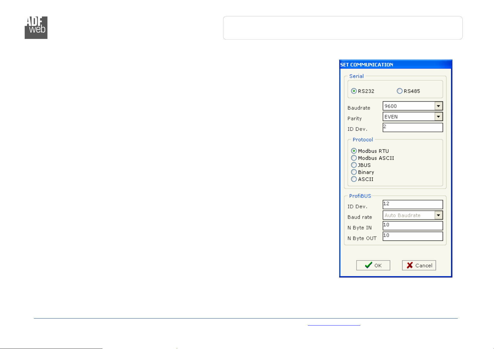
This section define the fundamental communication parameter of two Buses, Serial and ProfiBus.
By Pressing the "Set Communication" button from the main wndow for SW67562 (Fig. 2) the window
"Set Communication" appears (Fig. 3).
The Window is divided in two section, one for the Serial and the other for the ProfiBus.
The means of the fields for Serial are:
If the field “RS232” is checked, the serial line in use is the RS232, otherwise if field “RS485”
is checked, the serial line in use is the RS485;
In the field “Baud Rate” the baudrate for the serial line is defined;
In the field “Parity” the parity of the serial line is defined;
In the field “Dev. ID” the address for the serial side is defined;
In the subsection “Protocol” it is possible to select the protocol that you wish to use between
the following:
o Modbus RTU;
o Modbus ASCII;
o JBUS;
o Simple Binary Protocol;
o Simple ASCII Protocol.
The means of the fields for ProfiBus are:
In the field "ID DEV" the address for the ProfiBus side is defined;
In the field "Baud Rate" the baudrate for the ProfiBus is defined;
In the field "N Byte IN" the number of byte from the slave ProfiBus to the gateway are
defined;
In the field "N Byte OUT" the number of byte from the gateway to the slave ProfiBus are
defined.
Figure 3: “Set Communication” window
ADFweb.com Srl – IT31010 – Mareno – Treviso INFO: www.adfweb.com Phone +39.0438.30.91.31
Page 7
Industrial Electronic Devices
Document
code: MN67562
_ENG Revision 1
.002
Page
7
of 11
User Manual
ProfiBus Slave
to
Serial Communication
Slave
SET ACCESS:
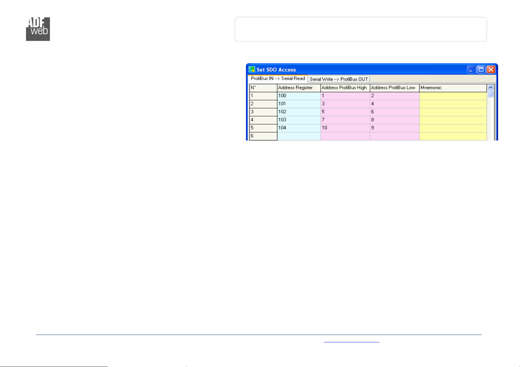
By pressing the “Set Access” button from the main
window for SW67562 (Fig. 2) the window “Set SDO Access”
appears (Fig. 4):
It is divided in two part, the "ProfiBus IN --> Serial Read" and
the "Serial Write --> ProfiBus OUT".
The first part ("ProfiBus IN --> Serial Read") is used to read
by using the Serial Line the data that arrived from the Slave
ProfiBus.
The second part ("Serial Write --> ProfiBus OUT") is used to
write by using the Serial Line the data that will be sent to the
Slave ProfiBus.
The Fields in the two table are the same:
In the field "Address Register" the address for the Serial Line is defined;
In the field "Address ProfiBus High" is defined the first byte where the data will be saved/loaded in the ProfiBus arrays;
In the field "Address ProfiBus Low" is defined the second byte where the data will be saved/loaded in the ProfiBus arrays;
In the field "Mnemonic" the description for the register is defined.
GDS FILE:
By pressing the “GDS File” button is possible to save the GDS file for the ProfiBus side.
With this feature you can save the configuration of the gateway of the ProfiBus side.
ADFweb.com Srl – IT31010 – Mareno – Treviso INFO: www.adfweb.com Phone +39.0438.30.91.31
Figure 4: “Set SDO Access” window
Page 8
Industrial Electronic Devices
Document
code: MN67562
_ENG Revision 1
.002
Page
8
of 11
User Manual
ProfiBus Slave
to
Serial Communication
Slave
UPDATE DEVICE:
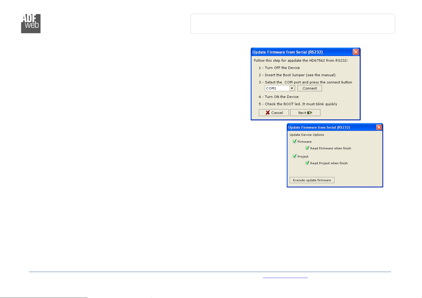
Section “Update Device” (Fig. 5):
In order to load the parameters or update the firmware in the gateway, follow these
instructions:
Turn off the Device;
Connect the Null Modem Cable Form your PC to the Gateway;
Insert the Boot Jumper (see the Fig. 1 for more info);
Select COM port and press the “Connect” Button;
Turn on the device;
Check the “BOOT Led”. It must to blink quickly (see the Fig. 1 for more info);
Press the “Next” Button;
Select which operations you want to do. Can select only Firmware or only
Project or both;
Press the “Execute update firmware” to start the upload;
When all the operation are “OK” turn off the device;
Disconnect the Boot jumper;
Disconnect the RS232 Cable;
Turn on the Device.
At this point the configuration/firmware on the device is correctly updated.
ADFweb.com Srl – IT31010 – Mareno – Treviso INFO: www.adfweb.com Phone +39.0438.30.91.31
Figure 5: “Update Device” window
Page 9
Industrial Electronic Devices
Document
code: MN67562
_ENG Revision 1
.002
Page
9
of 11
User Manual
ProfiBus Slave
to
Serial Communication
Slave
CHARACTERISTICS OF THE CABLES:
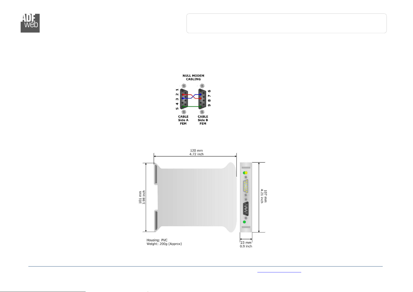
The connection from RS232 socket to a serial port (example one from a personal computer), must be made with a Null Modem cable (a
serial cable where the pins 2 and 3 are crossed).
It is recommended that the RS232C Cable not exceed 15 meters.
MECHANICAL DIMENSIONS:
Figure 6: Mechanical dimensions scheme
ADFweb.com Srl – IT31010 – Mareno – Treviso INFO: www.adfweb.com Phone +39.0438.30.91.31
Page 10

Industrial Electronic Devices
Document
code: MN67562
_ENG Revision 1
.002
Page
10
of 11
User Manual
ProfiBus Slave
to
Serial Communication
Slave
ORDER CODE:
Order Code: HD67562 - Gateway/Bridge – ProfiBus Slave to Serial Communication Slave
ACCESSORIES:
Order Code: AC34107 - Null Modem Cable Fem/Fem DSub 9 Pin 1,5 m
Order Code: AC34114 - Null Modem Cable Fem/Fem DSub 9 Pin 5 m
Order Code: AC34001 - Rail DIN - Power Supply 220/240V AC 50/60Hz – 12 V AC
Order Code: AC34002 - Rail DIN - Power Supply 110V AC 50/60Hz – 12 V AC
ADFweb.com Srl – IT31010 – Mareno – Treviso INFO: www.adfweb.com Phone +39.0438.30.91.31
Page 11
Industrial Electronic Devices
Document
code: MN67562
_ENG Revision 1
.002
Page
11
of 11
User Manual
ProfiBus Slave
to
Serial Communication
Slave
WARRANTIES AND TECHNICAL SUPPORT:
For fast and easy technical support for your ADFweb.com SRL products, consult our internet support at
www.adfweb.com.
Otherwise contact us at the address [email protected]
RETURN POLICY:
If while using your product you have any problem and you wish to exchange or repair it, please do the following:
1) Obtain a Product Return Number (PRN) from our internet support at www.adfweb.com. Together with the
request, you need to provide detailed information about the problem.
2) Send the product to the address provided with the PRN, having prepaid the shipping costs (shipment costs
If the product is within the warranty of twelve months, it will be repaired or exchanged and returned within three weeks.
If the product is no longer under warranty, you will receive a repair estimate.
PRODUCTS AND RELATED DOCUMENTS:
HD67121 Gateway CANopen / Canopen www.adfweb.com?product=HD67121
HD67002 Gateway CANopen / Modbus - RTU www.adfweb.com?product=HD67002
HD67004
HD67005
HD67134 Gateway CANopen / DeviceNet www.adfweb.com?product=HD67134
HD67117 CAN bus Repeater www.adfweb.com?product=HD67117
HD67216 CAN bus Analyzer www.adfweb.com?product=HD67216
billed to us will not be accepted).
Part Description URL
Gateway CANopen / Modbus – Ethernet TCP www.adfweb.com?product=HD67004
ADFweb.com Srl – IT31010 – Mareno – Treviso INFO: www.adfweb.com Phone +39.0438.30.91.31
 Loading...