

User Manual
Ethernet to RS232
/ RS485
Document code: MN67038-2_ENG Revision 1.400 Page 1 of 25
Temperat
ure range
-
30°C to 70°C
;
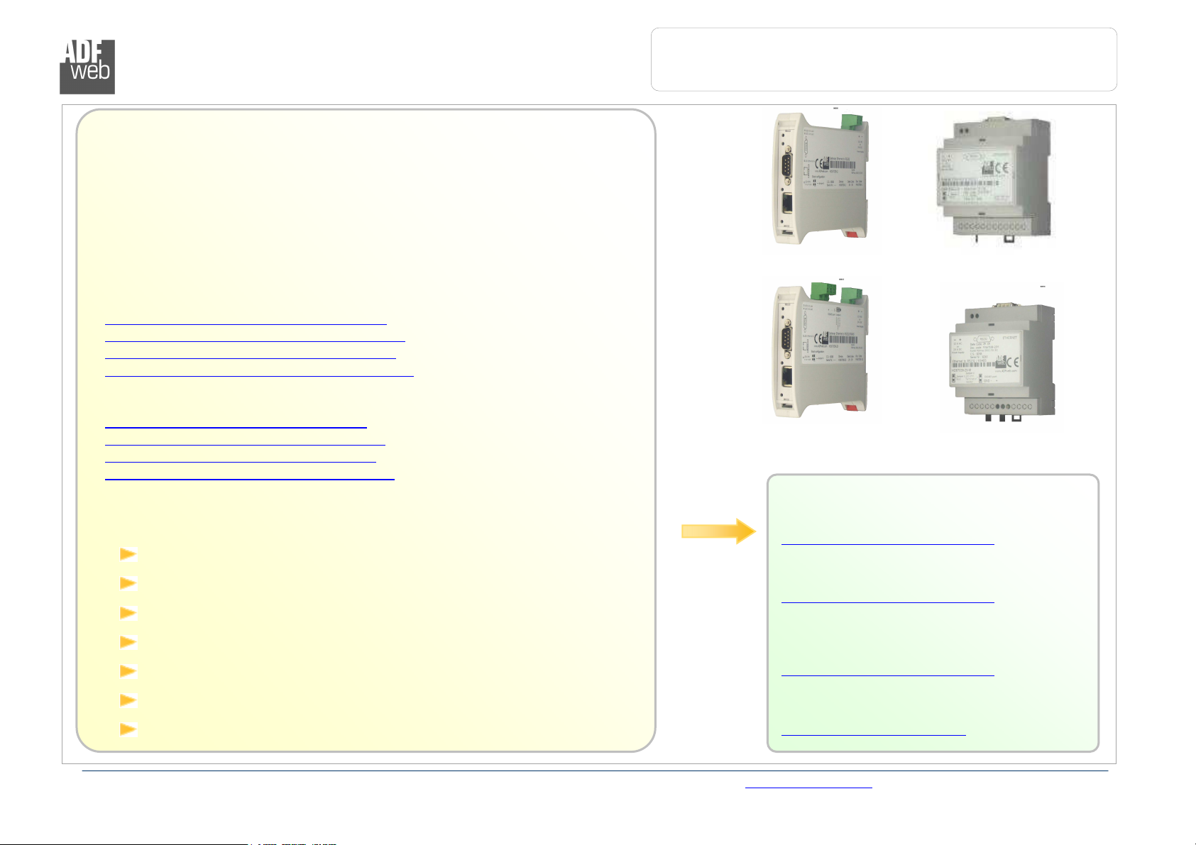
Products
HD67038
-
2
HD67038
-2-M
HD67038
-25
Industrial Electronic Devices
User Manual
Revision 1.400
English
Converter / Adapter
Ethernet to RS232 / RS485
(Order Code: HD67038-2 HD67038-2-M
HD67038-25 HD67038-25-M)
for Website information:
www.adfweb.com?Product=HD67038-2
www.adfweb.com?Product=HD67038-2-M
www.adfweb.com?Product=HD67038-25
www.adfweb.com?Product=HD67038-25-M
for Price information:
www.adfweb.com?Price=HD67038-2
www.adfweb.com?Price=HD67038-2-M
www.adfweb.com?Price=HD67038-25
www.adfweb.com?Price=HD67038-25-M
Benefits and Main Features:
Galvanic isolation between Ethernet and RS232
Protocol independent
Suitable for supervision software
SCADA/HMI and the connection to a Personal Computer
Automated control of the line directions.
Easy to use software configuration.
Similiar
For others Converter / Adapter:
RS232 / RS485
See also the following link:
www.adfweb.com?Product=HD67118
USB / RS485
See also the following link:
www.adfweb.com?Product=HD67119
Do you have an your customer protocol?
See the following link:
www.adfweb.com?Product=HD67003
Do you need to choose a device? do you want help?
Ask it to the following link:
www.adfweb.com?Cmd=helpme
HD67038-25-M
ADFweb.com Srl – IT31010 – Mareno – Treviso INFO: www.adfweb.com Phone +39.0438.30.91.31
Industrial Electronic Devices
User Manual
Ethernet to RS232
/ RS485
INDEX:
Page
INDEX 2
UPDATED DOCUMENTATION 2
REVISION LIST 2
WARNING 2
TRADEMARKS 2
CONNECTION SCHEME 3
CHARACTERISTICS 7
POWER SUPPLY 7
CONFIGURATION 8
USE OF SW67038 COMPOSITOR 8
GENERAL PARAMETER 9
OP. M
OP. M
OP. M
ODALITY REMOTE
ODALITY TUNNEL POINT TO POINT
ODALITY TUNNEL POINT TO MULTIPOINT
COM P
ORT
10
11
12
UPDATE VIA TCP 16
UPDATE VIA SERIAL 17
SOME EXAMPLES 18
CHARACTERISTICS OF THE CABLES 19
ACTIVE SERIAL DRIVER 20
CHANGE BAUD AND PARITY ON THE FLY 22
MECHANICAL DIMENSIONS 23
ORDER CODE 24
ACCESSORIES 24
WARRANTIES AND TECHNICAL SUPPORT 25
RETURN POLICY 25
PRODUCTS AND RELATED DOCUMENTS 25
UPDATED DOCUMENTATION:
Dear customer, we thank you for your attention and we remind you that you
need to check that the following document is:
Updated
Related to the product you own
To obtain the most recently updated document, note the “document code” that
appears at the top right-hand corner of each page of this document.
With this “Document Code” go to web page www.adfweb.com/download/ and
search for the corresponding code on the page. Click on the proper “Document
Code” and download the updates.
To obtain the updated documentation for the product that you own, note the
“Document Code” (Abbreviated written "Doc. Code" on the label on the product)
and download the updated from our web site www.adfweb.com/download/
REVISION LIST:
Revision
1.000 20/10/2008 Fl All First release version
1.100 02/07/2009 Ml All Revision
1.200 06/07/2010 FT All Revision
1.300 31/03/2011 Dp All Revision
1.400 28/03/2012 Dp All Revision
WARNING:
ADFweb.com reserves the right to change information in this manual about our
product without warning.
ADFweb.com is not responsible for any error this manual may contain.
TRADEMARKS:
All trademarks mentioned in this document belong to their respective owners.
Document code: MN67038-2_ENG Revision 1.400 Page 2 of 25
Date Author Chapter
Description
ADFweb.com Srl – IT31010 – Mareno – Treviso INFO: www.adfweb.com Phone +39.0438.30.91.31
Industrial Electronic Devices
User Manual
Ethernet to RS232
/ RS485
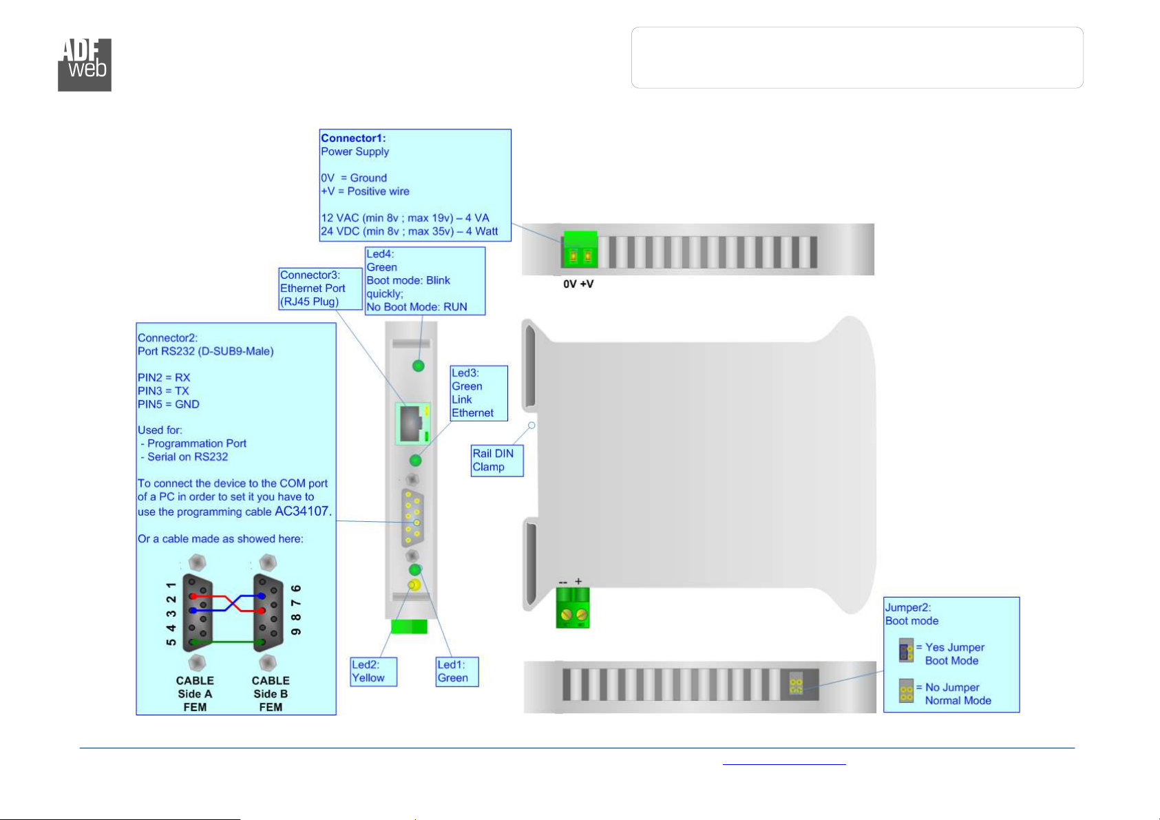
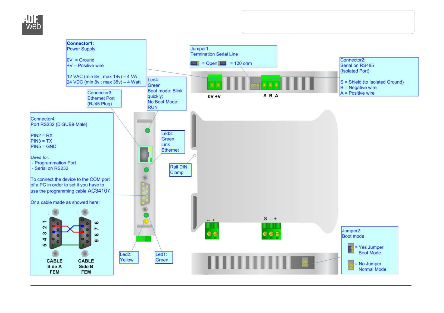
Figure 1: Connection scheme for HD67038
-2
CONNECTION SCHEME:
Document code: MN67038-2_ENG Revision 1.400 Page 3 of 25
ADFweb.com Srl – IT31010 – Mareno – Treviso INFO: www.adfweb.com Phone +39.0438.30.91.31
User Manual
Ethernet to RS232
/ RS485
Document code: MN67038-2_ENG Revision 1.400 Page 4 of 25
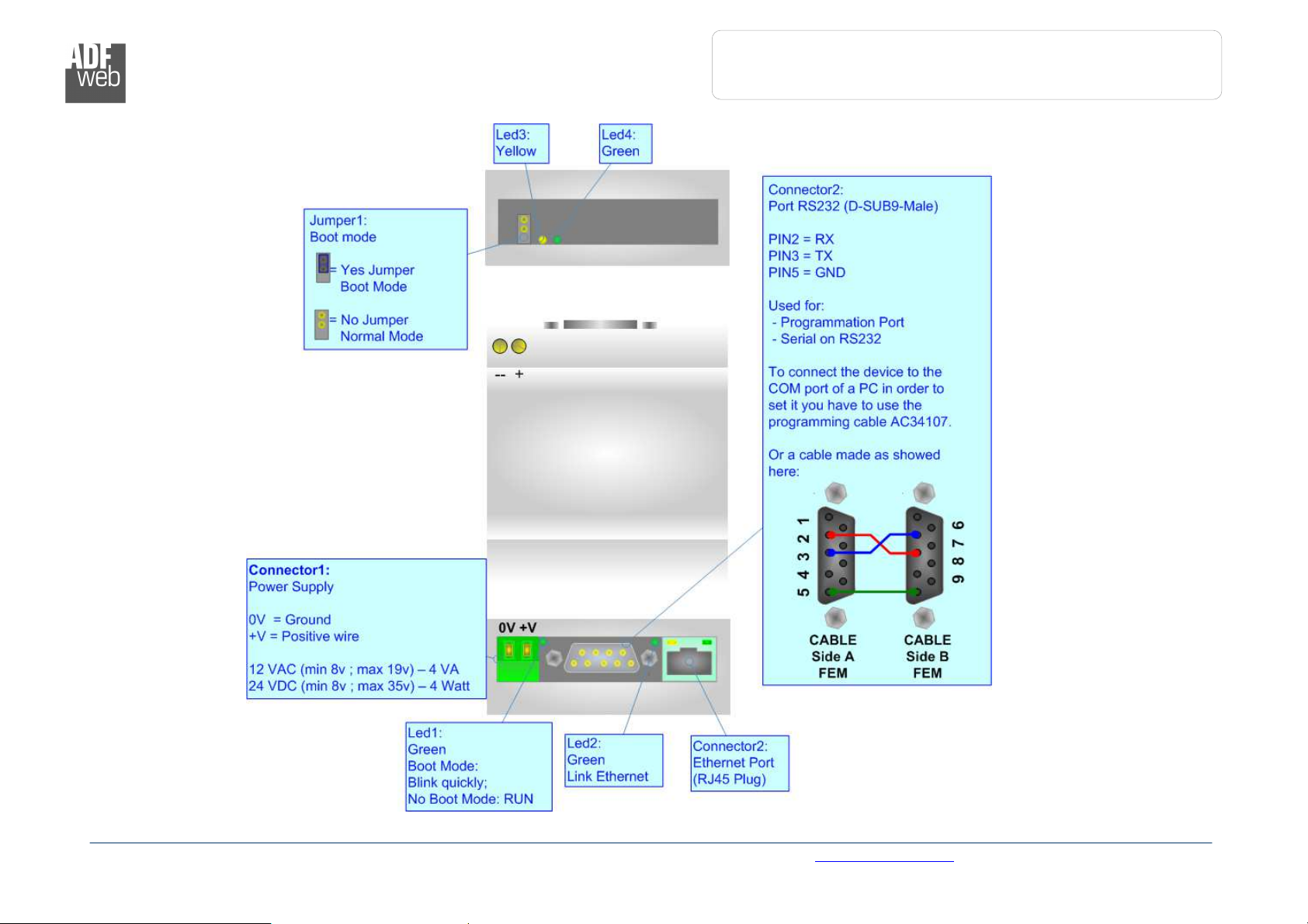
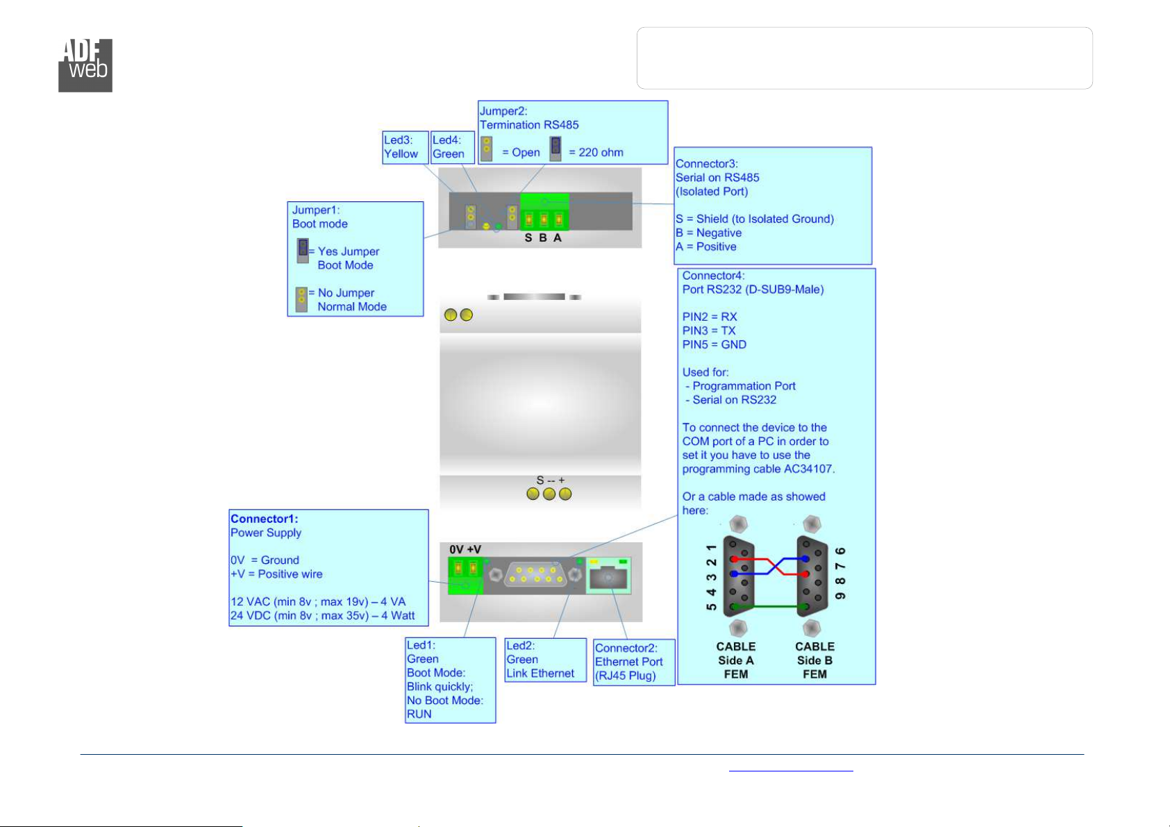
Figure
2
: Connection scheme for HD67038
-2-M
Industrial Electronic Devices
ADFweb.com Srl – IT31010 – Mareno – Treviso INFO: www.adfweb.com Phone +39.0438.30.91.31
User Manual
Ethernet to RS232
/ RS485
Document code: MN67038-2_ENG Revision 1.400 Page 5 of 25
Figure
3
: Connection scheme for HD67038
-25
Industrial Electronic Devices
ADFweb.com Srl – IT31010 – Mareno – Treviso INFO: www.adfweb.com Phone +39.0438.30.91.31
User Manual
Ethernet to RS232
/ RS485
Document code: MN67038-2_ENG Revision 1.400 Page 6 of 25
Figure
4
: Connection scheme for
HD67038
-25-M
Industrial Electronic Devices
ADFweb.com Srl – IT31010 – Mareno – Treviso INFO: www.adfweb.com Phone +39.0438.30.91.31

User Manual
Ethernet to RS232
/ RS485
Document code: MN67038-2_ENG Revision 1.400 Page 7 of 25
.
HD67038
-2
HD67038
-2-M
HD67038
-25
HD67038
-25-M
Industrial Electronic Devices
CHARACTERISTICS:
Ethernet to RS232/RS485 is a professional device for using COM port through Ethernet line.
The Converter allows the following characteristics:
Galvanic isolation between Ethernet and RS232 / RS485;
Rail DIN mountable;
Auto-sensing Ethernet 10/100;
Baud Rate and Parity changeable with software;
Possible Baud Rates: 1200, 2400, 4800, 9600, 19200, 38400, 57600, 115200 bps;
Fixed Stop bit (1);
Temperature range -30°C to 70°C;
EMS EN 61000-6-2.
POWER SUPPLY:
Recommended Power Supply
VDC VAC
24v 12v
VDC VAC
Vmin Vmax Vmin Vmax
8v 35v 8v 19v
Caution: Not reverse the polarity power
ADFweb.com Srl – IT31010 – Mareno – Treviso INFO: www.adfweb.com Phone +39.0438.30.91.31
Industrial Electronic Devices
User Manual
Ethernet to RS232
/ RS485
Figure
5: Main window
for SW67038
CONFIGURATION:
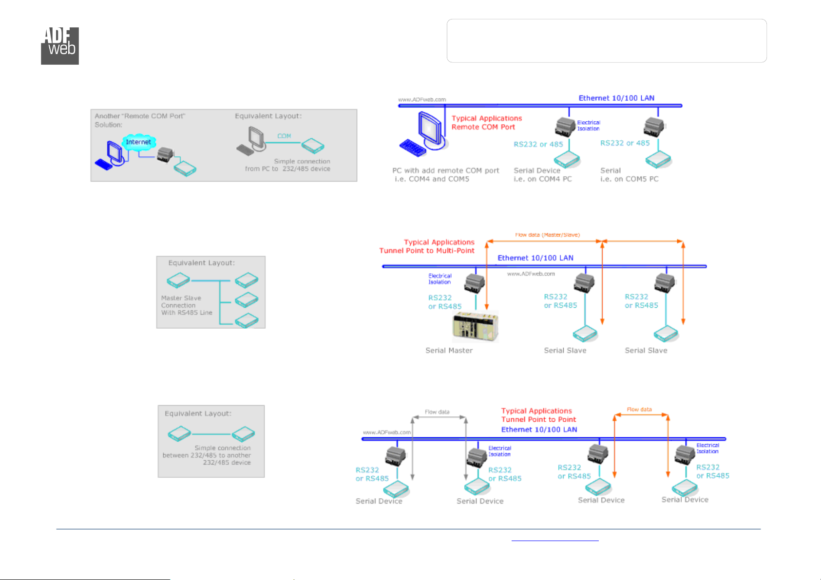
This device allows the following configurations:
Remote COM Port;
Tunnel Point to Point ( Ethernet bridge for a serial line);
Tunnel Point to Multipoint.
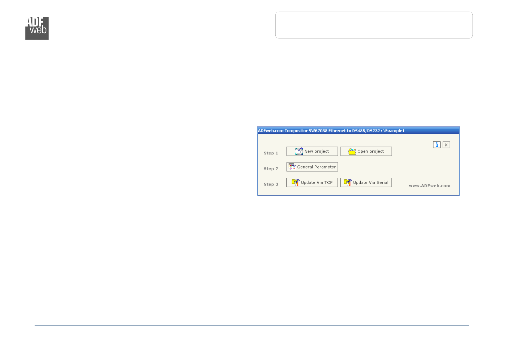
USE OF COMPOSITOR SW67038:
To configure the Converter use the available software that runs with
Windows, called SW67038. It is downloadable on the site
www.adfweb.com and its operation is described in this document.
When launching the SW67038 the right window appears (Fig. 5).
Document code: MN67038-2_ENG Revision 1.400 Page 8 of 25
ADFweb.com Srl – IT31010 – Mareno – Treviso INFO: www.adfweb.com Phone +39.0438.30.91.31

User Manual
Ethernet to RS232
/ RS485
Document code: MN67038-2_ENG Revision 1.400 Page 9 of 25
Industrial Electronic Devices
GENERAL PARAMETER:
By Pressing the “General Parameter” button from the main window for SW67038 (Fig. 5), the window “General Parameter” appears.
This window is divided in three sections: in the first you can select the Operating Modality, the second is used to configure the Ethernet and the
last to configure the Serial line.
In the section “Operating Modality” it is possible to select the function mode of the Converter from these options:
Remote COM Port;
Tunnel Point to Point;
Tunnel Point to Multipoint.
These operating modalities are described in the following pages.
ADFweb.com Srl – IT31010 – Mareno – Treviso INFO: www.adfweb.com Phone +39.0438.30.91.31

User Manual
Ethernet to RS232
/ RS485
Document code: MN67038-2_ENG Revision 1.400 Page 10 of 25
Figure
6: “
General Parameter
” window
(Remote COM Port)
Industrial Electronic Devices
O
PERATING MODALITY: REMOTE
COM P
ORT
It consists of a configuration in which the device is generally controlled by a PC
that is connected using the TCP protocol line on the 10001 port. It writes bytes
that automatically are sent on the serial line and each byte read from the serial
port is transmitted through the line to the connected PC.
The means of the fields for “Ethernet Configuration” are:
In the field “IP Address” the IP address of the Converter is defined;
In the field “SubNet Mask” the Subnet Mask of the Converter is defined;
In the field “Port” the Port of the Converter is defined;
If the field “Use Gateway” is checked, in the field below it is possible to
insert the IP Address of the gateway used for going out to the net in the
field under;
In the field “Socket Disconnect TimeOut (S)” enter a time in seconds. If
no data pass through the socket for the seconds defined, the socket
disconnects.
The means of the fields for “Serial Configuration” are:
If you are using HD67038-2 or HD67038-2-M Converter, the field
“RS232” must be checked; instead if you are using HD67038-25 or
HD67038-25-M Converter, if the field “RS485” is checked the serial line
in use is the RS485 otherwise is the RS232;
In the field “BaudRate” the velocity of the serial line in use is defined;
In the field “Parity” the parity of the serial line in use is defined.
If select the “Enable Change baudrate on the fly” is possible to change
the baudrate and parity from the Ethernet (see Change Baudrate and
Parity On The Fly chapter for more info).
In the field ”Port” the port to change baudrate and parity is defined.
The button "ACTIVE SERIAL DRIVER" is used to activate the "Serial to Ethernet Connector". For more details go to page 17.
ADFweb.com Srl – IT31010 – Mareno – Treviso INFO: www.adfweb.com Phone +39.0438.30.91.31

User Manual
Ethernet to RS232
/ RS485
Document code: MN67038-2_ENG Revision 1.400 Page 11 of 25
Industrial Electronic Devices
O
PERATING MODALITY: TUNNEL POINT TO POINT
A mode that allows for the extension of a serial line using a Ethernet Network.
The two devices in this mode must be configured in a coherent way between
each one, or in such a way that both read the IP address of the other one.
It is necessary to insert the IP address of the remote device in addition to the
set-up of the device’s line.
The means of the fields for “Ethernet Configuration” are:
In the field “IP Address” the IP address of the Converter is defined;
In the field “SubNet Mask” the Subnet Mask of the Converter is defined;
In the field “Port” the Port of the Converter is defined;
In the field “Remote IP” the IP of the second device connected to the
same line is defined;
In the fields “TCP” and “UDP” the protocol of the communication is
defined;
In the field “Force socket TCP open” is defined if the socket TCP try to
connect to start up;
If the field “Use Gateway” is checked, in the field below it is possible to
insert the IP Address of the gateway used for going out to the net in the
field under;
The means of the fields for “Serial Configuration” are:
If you are using HD67038-2 or HD67038-2-M Converter, the field
“RS232” must be checked; instead if you are using HD67038-25 or
HD67038-25-M Converter, if the field “RS485” is checked the serial line
in use is the RS485 otherwise is the RS232;
In the field “BaudRate” the velocity of the serial line in use is defined;
In the field “Parity” the parity of the serial line in use is defined.
The button "ACTIVE SERIAL DRIVER" is used to activate the "Serial to Ethernet Connector". For more details go to page 17.
Figure 7: “General Parameter” window (Tunnel Point to Point)
ADFweb.com Srl – IT31010 – Mareno – Treviso INFO: www.adfweb.com Phone +39.0438.30.91.31

Industrial Electronic Devices
User Manual
Ethernet to RS232
/ RS485
ultipoint
O
PERATING MODALITY: TUNNEL POINT TO MULTIPOINT WITH BROADCAST (MASTER SIDE
This mode allows a serial line to be extended into sections, using a LAN
line, where the device is on the side of the one that controls the line as
Master and the others that are on the client’s side.
To configure a device as Master the field “Master Side” of “Operating
Modality” section must be checked.
In the case of the master, it isn’t necessary to provide any other IP address
because the packets are sent in broadcast.
The means of the fields for “Ethernet Configuration” are:
Select the “Work with Broadcast”, in this way the master sends the
messages in Broadcast;
In the field “IP Address” the IP address of the Converter is defined;
In the field “SubNet Mask” the Subnet Mask of the Converter is
defined;
In the field “Port” the Port of the Converter is defined.
The means of the fields for “Serial Configuration” are:
If you are using HD67038-2 or HD67038-2-M Converter, the field
“RS232” must be checked; instead if you are using HD67038-25 or
HD67038-25-M Converter, if the field “RS485” is checked the serial
line in use is the RS485 otherwise is the RS232;
Document code: MN67038-2_ENG Revision 1.400 Page 12 of 25
)
In the field “BaudRate” the velocity of the serial line in use is
defined;
In the field “Parity” the parity of the serial line in use is defined.
The button "ACTIVE SERIAL DRIVER" is used to activate the "Serial to Ethernet Connector". For more details go to page 17.
ADFweb.com Srl – IT31010 – Mareno – Treviso INFO: www.adfweb.com Phone +39.0438.30.91.31
Figure 8: “General Parameter” window (Tunnel Point to M
Master Side)

User Manual
Ethernet to RS232
/ RS485
Industrial Electronic Devices
O
PERATING MODALITY: TUNNEL POINT TO MULTIPOINT WITH BROADCAST (SLAVE SIDE
To configure a device as Slave the field “Master Side” of “Operating
Modality” section must not be checked.
In the case of the slave it is necessary to provide the IP address of the
Master Converter.
The means of the fields for “Ethernet Configuration” are:
Select the “Work with Broadcast”, in this way the master sends the
messages in Broadcast;
In the field “IP Address” the IP address of the Converter is defined;
In the field “SubNet Mask” the Subnet Mask of the Converter is
defined;
In the field “Port” the Port of the Converter is defined;
In the field “Master IP” the IP address of the Master Converter is
defined.
The means of the fields for “Serial Configuration” are:
If you are using HD67038-2 or HD67038-2-M Converter, the field
“RS232” must be checked; instead if you are using HD67038-25 or
HD67038-25-M Converter, if the field “RS485” is checked the serial
line in use is the RS485 otherwise is the RS232;
In the field “BaudRate” the velocity of the serial line in use is
defined;
In the field “Parity” the parity of the serial line in use is defined.
The button "ACTIVE SERIAL DRIVER" is used to activate the "Serial to
Ethernet Connector". For more details go to page 17.
Figure 9: “General Parameter” window (Tunnel Point to Multipoint
Slave Side)
Document code: MN67038-2_ENG Revision 1.400 Page 13 of 25
)
ADFweb.com Srl – IT31010 – Mareno – Treviso INFO: www.adfweb.com Phone +39.0438.30.91.31

User Manual
Ethernet to RS232
/ RS485
Document code: MN67038-2_ENG Revision 1.400 Page 14 of 25
Industrial Electronic Devices
O
PERATING MODALITY: TUNNEL POINT TO MULTIPOINT WITH KEEP ALIVE (MASTER SIDE
This mode allows a serial line to be extended into sections, using a LAN line, where the
device is on the side of the one that controls the line as Master and the others that are
on the client’s side.
To configure a device as Master the field “Master Side” of “Operating Modality” section
must be checked.
In the case of the master receive the messages of “Keep Alive” from the slaves presents
in the network and send the data to that devices.
The means of the fields for “Ethernet Configuration” are:
Select the “Work with Keep Alive”, in this way the master sends the messages to
all the devices that send the “Keep Alive” messages;
In the field “IP Address” the IP address of the Converter is defined;
In the field “SubNet Mask” the Subnet Mask of the Converter is defined;
In the field “Port” the Port of the Converter is defined.
In the field “TimeOut Keep Alive (S)” the maximum time Master device waits to
consider a slave no more available.
In the field “Keep Alive Port” the Port of Keep Alive is defined.
If the field “Use Gateway” is checked, in the field below it is possible to insert
the IP Address of the gateway used for going out to the net in the field under;
The means of the fields for “Serial Configuration” are:
If you are using HD67038-2 or HD67038-2-M Converter, the field “RS232” must
be checked; instead if you are using HD67038-25 or HD67038-25-M Converter,
if the field “RS485” is checked the serial line in use is the RS485 otherwise is the
RS232;
In the field “BaudRate” the velocity of the serial line in use is defined;
In the field “Parity” the parity of the serial line in use is defined.
The button "ACTIVE SERIAL DRIVER" is used to activate the "Serial to Ethernet Connector". For more details go to page 17.
)
Figure 10: “General Parameter” window (Tunnel Point
to Multipoint Master Side)
ADFweb.com Srl – IT31010 – Mareno – Treviso INFO: www.adfweb.com Phone +39.0438.30.91.31

User Manual
Ethernet to RS232
/ RS485
Document code: MN67038-2_ENG Revision 1.400 Page 15 of 25
Industrial Electronic Devices
O
PERATING MODALITY: TUNNEL POINT TO MULTIPOINT WITH KEEP ALIVE (SLAVE SIDE
To configure a device as Slave the field “Master Side” of “Operating Modality” section
must not be checked.
In the case of the slave it is necessary to provide the IP address of the Master
Converter.
The means of the fields for “Ethernet Configuration” are:
Select the “Work with Keep Alive”, in this way the master sends the messages to
all the devices that send the “Keep Alive” messages;
Select the “Work with Broadcast”, in this way the master sends the messages in
Broadcast;
In the field “IP Address” the IP address of the Converter is defined;
In the field “SubNet Mask” the Subnet Mask of the Converter is defined;
In the field “Port” the Port of the Converter is defined;
In the field “Master IP” the IP address of the Master Converter is defined;
In the field “Keep Alice every (S)” the Time beetwen the “Keep Alive” messages
is defined;
In the field “Keep Alive Port” the Port of Keep Alive is defined;
If the field “Use Gateway” is checked, in the field below it is possible to insert the
IP Address of the gateway used for going out to the net in the field under;
The means of the fields for “Serial Configuration” are:
If you are using HD67038-2 or HD67038-2-M Converter, the field “RS232” must
be checked; instead if you are using HD67038-25 or HD67038-25-M Converter, if
the field “RS485” is checked the serial line in use is the RS485 otherwise is the
RS232;
In the field “BaudRate” the velocity of the serial line in use is defined;
In the field “Parity” the parity of the serial line in use is defined.
The button "ACTIVE SERIAL DRIVER" is used to activate the "Serial to Ethernet Connector". For more details go to page 17.
)
Figure 11: “General Parameter” window (Tunnel
Point to Multipoint Slave Side)
ADFweb.com Srl – IT31010 – Mareno – Treviso INFO: www.adfweb.com Phone +39.0438.30.91.31
Industrial Electronic Devices
User Manual
Ethernet to RS232
/ RS485
Figure
12: “Update Via TCP” windows
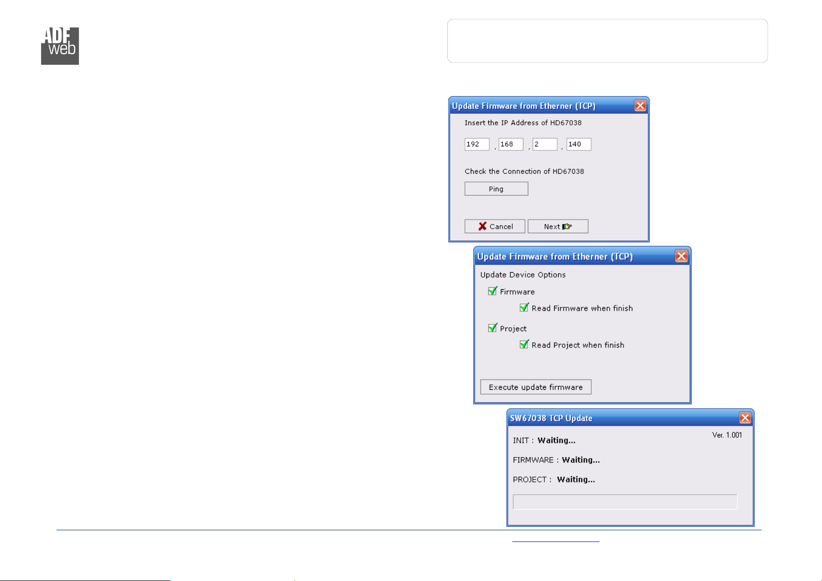
UPDATE VIA TCP:
Section “Update Via TCP” (Fig. 10):
In order to load the parameters or update the firmware in the gateway,
follow these instructions:
Connect the Ethernet cable to the gateway;
Insert the IP address of the Converter;
Press the “Ping” button for check the connection of the Converter;
Press the “Next” button;
Select the operations you want to do. You can select only “Firmware”,
only “Project” or both of them;
Press the “Execute update firmware” button to start the upload.
When all the operations are “OK” the configuration/firmware on the device is
correctly updated.
Document code: MN67038-2_ENG Revision 1.400 Page 16 of 25
ADFweb.com Srl – IT31010 – Mareno – Treviso INFO: www.adfweb.com Phone +39.0438.30.91.31
Industrial Electronic Devices
User Manual
Ethernet to RS232
/ RS485
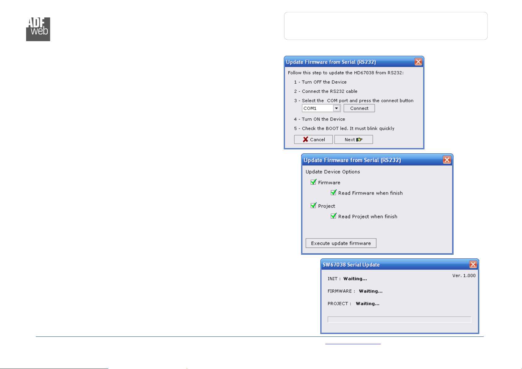
UPDATE VIA SERIAL:
Section “Update Via Serial” (Fig. 11):
In order to load the parameters or update the firmware in the gateway,
follow these instructions:
Turn OFF the device;
Connect the Null Modem cable from your PC to the gateway;
Insert the Boot Jumper (For more info see the “Connection scheme” of
the Converter);
Turn ON the device;
Check the “BOOT Led”. It must blink quickly (more info see the
“Connection scheme” of the Converter);
Select the COM port and press the “Connect” button;
Press the “Next” button;
Select the operations you want to do. You can select only “Firmware”,
only “Project” or both of them;
Press the “Execute update firmware” button to start the upload;
When all the operations are “OK” turn OFF the device;
Disconnect the Boot Jumper;
Turn ON the device.
At this point the configuration/firmware on the device is correctly updated.
Document code: MN67038-2_ENG Revision 1.400 Page 17 of 25
ADFweb.com Srl – IT31010 – Mareno – Treviso INFO: www.adfweb.com Phone +39.0438.30.91.31
Figure 13: “Update Via Serial” windows
Industrial Electronic Devices
User Manual
Ethernet to RS232
/ RS485
Figure
14:
Som
e examples
SOME EXAMPLES:
Document code: MN67038-2_ENG Revision 1.400 Page 18 of 25
ADFweb.com Srl – IT31010 – Mareno – Treviso INFO: www.adfweb.com Phone +39.0438.30.91.31
User Manual
Ethernet to RS232
/ RS485
Document code: MN67038-2_ENG Revision 1.400 Page 19 of 25
Figure 1
5
: Null modem cabling
Industrial Electronic Devices
CHARACTERISTICS OF THE CABLES:
E
THERNET
The connection with the Ethernet socket must be done with a Ethernet Cable with a RJ45 Plug.
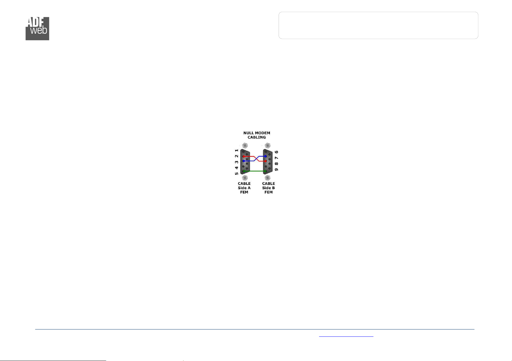
RS232:
The connection from RS232 socket to a serial port (example one from a personal computer) must be made with a Null Modem cable (a serial
cable where the pins 2 and 3 are crossed).
It is recommended that the RS232C Cable not exceed 15 meters.
RS485:
The connection with the RS485 socket must be done with a twisted and shielded cable.
:
ADFweb.com Srl – IT31010 – Mareno – Treviso INFO: www.adfweb.com Phone +39.0438.30.91.31
User Manual
Ethernet to RS232
/ RS485
Document code: MN67038-2_ENG Revision 1.400 Page 20 of 25
Industrial Electronic Devices
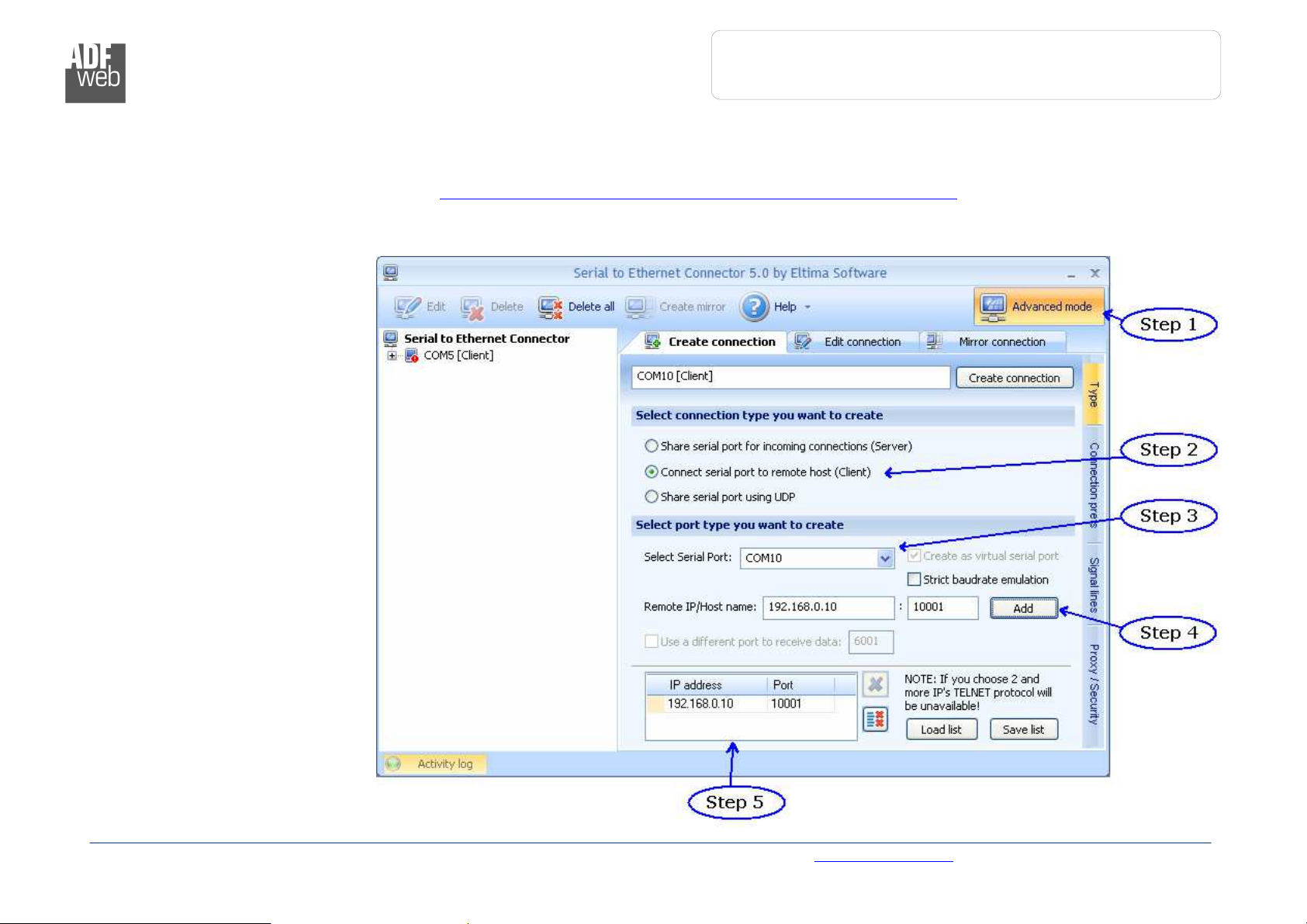
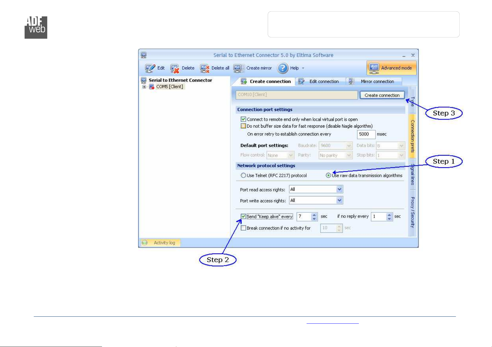
ACTIVE SERIAL DRIVER:
Before pressing the “Active Serial Driver” button from the “General Parameter” window it is necessary to download the “Serial to Ethernet
Connector” software from the following link: www.adfweb.com/download/filefold/serial_ethernet_connector.zip.
After the installation of the software you have to enter in the SW67038, go into the “General Parameter” section and press the “ACTIVE SERIAL
DRIVER” button. At this point it is possible to configure the virtual COM port following these steps:
Go in the “Type” Section.
Step 1 – Active the Advanced
Mode;
Step 2 – Active the Client Mode;
Step 3 – Select the COM port to
use with the device. It is better if
you use a COM port that does not
exist in your system;
Step 4 – Insert the IP Address
and the Port of the Device and
then press the “ADD” button;
Step 5 – Check that the IP and
the Port are correct.
ADFweb.com Srl – IT31010 – Mareno – Treviso INFO: www.adfweb.com Phone +39.0438.30.91.31
Figure 16: “Type” window
Industrial Electronic Devices
User Manual
Ethernet to RS232
/ RS485
Figure
17: “Connection prefs” window
Go in the “Connection prefs”
Section.
Step 1 – Select the RAW
protocol;
Step 2 – Select the “Send Keep
alive” option;
Step 3 – Confirm the parameters
and create the Virtual COM port.
Document code: MN67038-2_ENG Revision 1.400 Page 21 of 25
ADFweb.com Srl – IT31010 – Mareno – Treviso INFO: www.adfweb.com Phone +39.0438.30.91.31

User Manual
Ethernet to RS232
/ RS485
Document code: MN67038-2_ENG Revision 1.400 Page 22 of 25
Industrial Electronic Devices
CHANGE BAUDRATE AND PARITY ON THE FLY:
Enable the option “Enable change baudrate on the fly” in the modality “Remote COM Port” is possible to change the baudrate and the parity of
the serial port by sending a TCp frame into the post selected “Port”. The new baudrate and parity is saved in RAM so when you turn off the
device you lost these parameter and the device start always with the default value.
You can use this modality only in the “Remote COM port” modality.
The packet to send for change these parameters is:
BAUD=<baud value>;PARITY=<parity value>;
The admited value for Baudrate are;
1200, 2400, 4800, 9600, 19200, 38400, 57600 and 115200
The Admited value for Parity are:
N (= None)
O (= Odd)
E (= Even)
Example.
To set the Baudrate at 115200 and Odd parity you have to send,
In ASCII:
BAUD=115200;PARITY=0;
In exadecimal:
[42][41][55][44][3D][31][31][35][32][30][30][3B][50][41][52][49][54][59][3D][4F][3B]
ADFweb.com Srl – IT31010 – Mareno – Treviso INFO: www.adfweb.com Phone +39.0438.30.91.31
User Manual
Ethernet to RS232
/ RS485
Document code: MN67038-2_ENG Revision 1.400 Page 23 of 25
Figure
20
: Mechanical dimension
s scheme for HD67038
-25
Industrial Electronic Devices
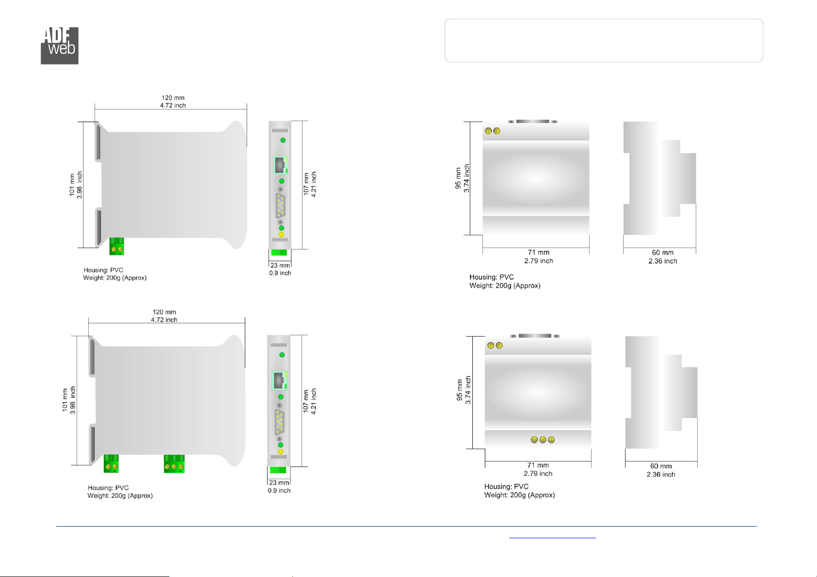
MECHANICAL DIMENSIONS:
Figure 18: Mechanical dimensions scheme for HD67038-2 Figure 19: Mechanical dimensions scheme for HD67038-2-M
ADFweb.com Srl – IT31010 – Mareno – Treviso INFO: www.adfweb.com Phone +39.0438.30.91.31
Figure 21: Mechanical dimensions scheme for HD67038-25-M

User Manual
Ethernet to RS232
/ RS485
Document code: MN67038-2_ENG Revision 1.400 Page 24 of 25
Industrial Electronic Devices
ORDER CODE:
Order Code: HD67038-2 - Converter – Ethernet to RS232
Order Code: HD67038-2-M - Converter – Ethernet to RS232 (Different enclosure)
Order Code: HD67038-25 - Converter – Ethernet to RS232 / RS485
Order Code: HD67038-25-M - Converter – Ethernet to RS232 / RS485 (Different enclosure)
ACCESSORIES:
Order Code: AC34001 - Rail DIN - Power Supply 220/240V AC 50/60Hz – 12 V AC
Order Code: AC34002 - Rail DIN - Power Supply 110V AC 50/60Hz – 12 V AC
Order Code: AC34104 - European Input - Power Supply 230V AC 50Hz – 12 V DC
ADFweb.com Srl – IT31010 – Mareno – Treviso INFO: www.adfweb.com Phone +39.0438.30.91.31
User Manual
Ethernet to RS232
/ RS485
Document code: MN67038-2_ENG Revision 1.400 Page 25 of 25
Industrial Electronic Devices
WARRANTIES AND TECHNICAL SUPPORT:
For fast and easy technical support for your ADFweb.com SRL products, consult our internet support at www.adfweb.com.
Otherwise contact us at the address support@adfweb.com
RETURN POLICY:
If while using your product you have any problem and you wish to exchange or repair it, please do the following:
1) Obtain a Product Return Number (PRN) from our internet support at www.adfweb.com. Together with the request, you need to provide detailed information
about the problem.
2) Send the product to the address provided with the PRN, having prepaid the shipping costs (shipment costs billed to us will not be accepted).
If the product is within the warranty of twelve months, it will be repaired or exchanged and returned within three weeks. If the product is no longer under warranty,
you will receive a repair estimate.
PRODUCTS AND RELATED DOCUMENTS:
Part Description URL
HD67118 Converter RS232 to RS485 Isolated www.adfweb.com?Product=HD67118
HD67119 Converter USB 2.0 to RS485 Isolated www.adfweb.com?Product=HD67119
HD67507 Gateway Modbus TCP Server to RTU Master www.adfweb.com?Product=HD67507
HD67510 Gateway Modbus TCP Client to RTU Slave www.adfweb.com?Product=HD67510
ADFweb.com Srl – IT31010 – Mareno – Treviso INFO: www.adfweb.com Phone +39.0438.30.91.31
 Loading...