

Page 1
A
RF44
UART TTL modules
User Guide
Ref. 08-07-V5-lmn p. 1
Page 2

No part of this document may be reproduced or transmitted (in electronic or
paper version, photocopy) without Adeunis RF consent.
This document is subject to change without notice.
All trademarks mentioned in this guide are the prop erty of their respective
owner.
ADEUNIS RF
283, rue Louis Néel
38920 Crolles
France
Phone +33 (0)4 76 92 07 77
Fax +33 (0)4 76 08 97 46
Ref. 08-07-V5-lmn
Ref. 08-07-V5-lmn p. 2
Page 3

RF44
TOP
A
User Guide
Table of Contents
About this Document ........................................................................2
Declaration of Conformity ................................................................3
Overview...........................................................................................4
Interface ...........................................................................................4
Mechanical specification........................................................................4
Signal description.................................................................................5
Directions are noted from module point of view...............................5
Radio Communication.......................................................................5
Available Channels ...............................................................................5
Channel selection .................................................................................6
Antenna requirements ..........................................................................6
Transceiver operating mode .............................................................7
Serial data rate ....................................................................................8
Command mode...................................................................................8
Transceiver mode.................................................................................9
Powerdown Mode...............................................................................10
AT Commands .................................................................................10
Description ........................................................................................10
Set of commands ...............................................................................11
Register description............................................................................12
Transceiver state machine ..................................................................13
Specifications..................................................................................14
ANNEX 1 : Firmware and document................................................15
Ref. 08-07-V5-lmn p. 1
Page 4

TOP
About this Document
RF44
A
User Guide
This guide describes the A
RF44
devices, their options and accessories
Ref. 08-07-V5-lmn p. 2
Page 5

RF44
TOP
A
User Guide
Declaration of Conformity
Manufacturer’s name: ADEUNIS R.F.
Manufacturer’s address Parc Technologique PRE ROUX IV
38920 CROLLES - FRANCE
declares that the product if used and installed according to the user guide available on
our web site www.adeunis-rf.com
Product Name: ARF44
Product Number(s): ARF7419A
is designed to comply with the RTTE Directive 99/5/EC:
EMC: according to the harmonized standard EN 301 489.
Safety: according to the standard EN 60950-1/2001
Radio: according to harmonized standard EN 300-220 covering essential
radio requirements of the RTTE directive.
Notes: - Conformity has been evaluated according to the procedure
described in Annex III of the RTTE directi v e.
- Receiver class (if applicable): 3.
According to the 1999/519/EC recommendation, minimum distance between the product
and the body could be required depending on the module integration.
Warnings: - CE marking applies only to End Products: Because this equipment is only a
subassembly, conformity testing has been reduced (equipment has been design in
accordance to standards but full testing is impossible). Manufacturer of End Products,
based on such a solution, has to insure full conformity to be able to CE label marking.
- As the integration of a radio module requires wireless technological
knowledge, ADEUNIS RF proposes its technical proficiency to its customers for a precompliance qualification of end products. In case of no-conformity, ADEUNIS RF will not
be held back responsible if this stage has not been realised.
Crolles, November 6th, 2007
VINCENT Hervé / Quality manager
283 rue Louis NEEL
Download of the user guide
Thank you for having chosen the ADEUNIS RF products.
User guides can be uploaded directly on our web site www.adeunis-rf.com
Index Products
Paragraph OEM Modules > UART TTL Transceivers
Print version available upon request
9 Tel : +33 4 76 92 07 77
9 Email : arf@adeunis-rf.com
Ref. 08-07-V5-lmn p. 3
Page 6
RF44
TOP
A
User Guide
Overview
RF44
The A
frame to be sent to a similar piece of equipment. The communication is halfduplex.
The operating parameters of these radio transceivers can be fully updated
through AT commands via the serial link.
4 radio transceiver converts data from a serial link into a radio
Interface
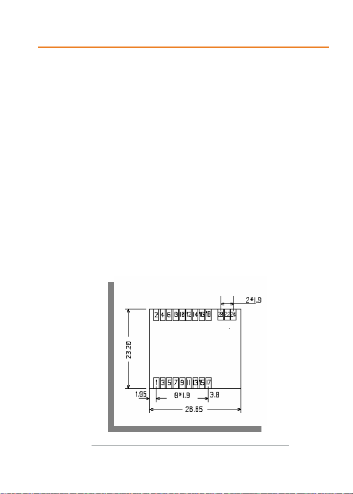
Mechanical specification
The transceiver is available under SMD format without printed antenna.
Figure 1: mécanique version SMD sans antenne imprimée
Ref. 08-07-V5-lmn p. 4
Page 7

TOP
Signal description
RF44
A
User Guide
Pin
number
Pin name
I/O direction Description
Power and reset
1, 17, 18 GND
Digital GND (connected with
radio GND)
2 VCC Power supply
3 /Reset Reset
RF interface
20 GND RF
Radio GND (connected with
digital GND)
22 RF in/out RF Antenna IN/OUT
24 GND RF
Masse radio (connected with
digital GND)
Serial interface
14 RxD I Serial input.
16 TxD O Serial output
Powerdown
4 Power-down
I Powerdown mode management
(leave unconnected if not used)
Not used
5, 6, 7, 8, 9, 10,
11, 12, 13, 15
Reserved
O
Directions are noted from module point of view.
Radio Communication
Available Channels
This module modem has 14 channels over the 863-870 MHz Band that can
be selected using AT commands.
The channels are selected according to the following table:
Ref. 08-07-V5-lmn p. 5
Page 8

TOP
Channel
S200
Frequency
(MHz)
13 863,25
12 863,75
11 864,25
10 864,75
9 865,25
8 865,75
7 866,25
6 866,75
5 867,25
4 867,75
3 868,25
2 868,75
1 869,525
0 869,75
Channel selection
The S200 register allows choosing the desired channel.
Antenna requirements
RF44
A
User Guide
This module is not available with printed an tenna. An external one has to be
added to achieve correct communication between the products. Several
possibilities:
The best technical/economical compromise is a ¼ wave (8.6 cm length)
antenna soldered on the “mother board”. The link between the RFin_out pin
of the module and the antenna should be a 50Ω line. The larger the ground
plane around the antenna, the more efficient and "isotropic" it will be.
If necessary, this antenna can be distant than ks to a coaxial cab le connected
to the “mother board”; the line must be a 50Ω line.
Ref. 08-07-V5-lmn p. 6
Page 9

RF44
TOP
A
User Guide
RSSI Reading
The RSSI (Received Strength Signal Indicator) gives an indication for the
received power level.
It could be accessed with AT commands.
-120 -100 -80 -60 -40 -20 0
0
-20
-40
-60
RSSI Readout (dBm )
Input Power (dBm)
-80
-100
-120
The RSSI level is only an indication. Use this level with care due to the
dispersion between components.
The schema above could be modified from one to another product. The
operating temperature could also have an impact on these dispersions.
The RSSI level could also indicate the potential presence of jammer in the
used channel.
The RSSI is a necessary but not sufficient condition to obtain a
correct reception.
Transceiver operating mode
Two operating modes are available :
Command mode (usage of AT commands)
Ref. 08-07-V5-lmn p. 7
Page 10

RF44
TOP
A
User Guide
Transceiver or normal mode (serial data are transmitted on radio link)
At power up the transceiver is in transceiver mode: it i s ab le to send / receive
data to / from the radio link according to its current parameter configuration.
Serial data rate
This module is only available with one data rate: 19200bps, 8 data bits, 1
stop bit, no parity, no flow control.
Command mode
The command mode is used to read and update the modem configuration
registers using AT command.
N
OTE
The AT command can be locked using ATPWD command.
In command mode, the radio is inhibited (reception and transmission),
excepted when using test command.
Entering command mode :
sequence of 3 consecutive + character s is accep ted only if n o character have
been seen before and after the +++ sequence. Register (S214) defines the
silence duration. The ‘O’ char is returned if the +++ sequence has been
accepted.
Tips 1 :
if you are using a terminal (such as Hyperterm), you have to send
the +++ sequence using a text file (first create a text file containing only the
+++ characters, and then use in Hyperterm the command “Send text file” in
the “Transfer menu”)
issues on the serial link a +++ sequence. The
Ref. 08-07-V5-lmn p. 8
Page 11

TOP
Tips 2 :
RXD
line
Idle line for S214
duration
A
+++ (consecut ive) Idle line for S214
duration
+
+
+
RF44
User Guide
TRANSCEIVER MODE
COMMAND
MODE
Exiting command mode
(return back in transceiver mode): send the serial
command
ATO <cr>
Transceiver mode
In transceiver mode, the module works with a transparent protocol: When
transmitting, data received from the serial link are transm itted on the radio
link. When data are received on the radio link, these data are sent on the
serial link. The module acts as a wire serial link.
The communication is always half-duplex. The radio transmission is
processed prior to the radio reception (when the transceiver is sending a
radio frame, it is not able to decode any incoming radio frame).
If no data are sent on the serial link, the modem is waiting for radio
reception. Each radio frame sent by another modem is received and the
validated data extracted from the radio frame are sent on the serial link.
All the data received on the serial link are encapsulated in a radio frame.
When acting as transceiver, the radio frame transmission starts as soon has a
char is available on the serial link.
The radio frame format is :
<Preamble><synchro>DATA <postambule>.
Preamble, synchronisation and postambule are used for the radio reception.
Ref. 08-07-V5-lmn p. 9
Page 12

RF44
TOP
A
User Guide
Powerdown Mode
In powerdown mode, the power consumption is reduced to reach less than
3µA. In this state, the module is not ab le to rece ive or transm it any d ata and
is not able to enter command mode.
The powerdown mode is controlled by pin 4 of the module. This pin is tied to
VCC when in transceiver or command mode. If powerdown mode is not used,
the pin can be leaved unconnected.
The powerdwon mode is entered by driving the powerdown pin to 0V. The
mode is activated by the detection of a high to low transition on this pin. The
powerdown state is reached after a typical delay of about 2ms. The pull up
on the pin is by passed during powerdown to get the better powerdown
consumption.
The powerdown mode is exited by actively driving the powerdown pin to
VCC. The mode is deactivated by the detection of a low to high transition on
this pin. The module is ready for sending new data after a typical delay of
3ms.
AT Commands
Description
AT commands are interpreted only when the transceiver is in
Command mode.
Command: are used to read and update the modem parameters
A command starts with the 2 ASCII ‘AT’ characters . ‘AT’ means ‘Attention’
follow with one or several characters or other data.
Each command is ended with <cr> (carriage return).
Response: is sent back for each command on the serial link.
The answer is :
‘O’<cr> (ASCII character 0x4F) for accepted command (or OK command)
‘E’<cr> for error
Specific string when specified
Ref. 08-07-V5-lmn p. 10
Page 13

TOP
Set of commands
RF44
A
User Guide
Commands
Operating mode selectin
Description
ATO Return back to transceiver mode.
<silence>+++<silence> Command mode activation. The +++ sequence must be
preceded and followed by a calibrated silence (no other
character)
Registers management
ATSn? Displays the Sn register content where n represents the
register number.
The response has the following format:
Sn=y<cr><lf>
ATSn=m Sets the Sn register value with ‘m’. n represents the register
number..
AT&W Saves the new register configuration in EEPROM. Each time
you switch on the modem, the EEPROM configuration will be
loaded in the modem registers.
AT/S Displays all register values. The response has the following
format:
Sxxx=y<cr><lf> for each register.
AT/V Software version display. The response has the following
format:
Adeunis RF : ARF34 Vxx.yy<cr><lf>
ATR Restore the register default values
ATPWD=m m = pin code (register S205) : unlock all AT commands.
m = 0000 : set registers to default value and unlock all AT
commands.
Test modes
ATT1 Pure Carrier (data=0) transmission using current channel.
The output of this mode is achieved by reception of any
character on the serial link.
ATT2 Pure Carrier (data=1) transmission using current channel.
The output of this mode is achieved by reception of any
character on the serial link.
Ref. 08-07-V5-lmn p. 11
Page 14

RF44
TOP
A
User Guide
ATT3 2.45 kHz modulation using current channel. The output of
ATT8 Reception test mode. TP1 is set when more than 80% of
this mode is achieved by reception of any character on the
serial link.
bits are demodulated properly.
Register description
The register value could be updated using the ATSn=m<cr> command and
displayed using ATSn?<cr> command.
At power-up, the previous transceiver configuration is restored from E2PROM
(non volatile) to RAM. The registers are located in RAM registers, any
modification is performed on RAM registers: To save current register
configurations, it is necessary to use the AT&W<cr> command (If no t, the
updated parameters are lost in case of power shortage).
The registers are shared in 2 types: read only (R) or read/write (R/W)
Type Regis-
R/W S200 Channel
R S230 RSSI Displays the reception level of
R/W S205 Pin code Pin code value
R/W S207 Pin code
R/W S214 Command
N
OTE 1
ter
(S200 register) see chapter Channel selection
Function Description Default
Radio management
0 1
number
the latest received message.
Response: S2 30=-xxx
dBm<cr><lf> with xxx decimal
value
Command mode management
Value 0000 is not allowed
activation
timeout
0 pin code disabled
1 pin code enabled
Time out duration for detecting
the +++ pattern, unit ms. From
3 up to 240.
value
none
1111
0
6
Note
Ref. 08-07-V5-lmn p. 12
Page 15

RF44
TOP
A
User Guide
Transceiver state machine
When operating in transceiver mode the 'RF transmission' state machine is:
Idle state of the transceiver: by default the transceiver is waiting for
incoming data on the serial link and for incom ing radio frame on the radio
link. The serial link has a higher priority than the radio link ( if a radio frame
is demodulated meanwhile some characters are detected on the serial link,
the radio frame will be discarded and the serial incoming data will be
processed).
Processing incoming serial data: the incoming serial data are internally
buffered. The buffered data are sent on a radio frame (the RF modulation is
started) when at least one data is available and the preambule + synchro has
been sent on the radio
Processing incoming radio frame: the valid data are extracted from the
incoming radio frame and internally buffered. The buffered data are sent on
the fly to the serial module output. The internal buf fer is limited to 64 bytes.
Ref. 08-07-V5-lmn p. 13
Page 16

TOP
Specifications
RF44
A
User Guide
Embedded protocol ADEUNIS RF enhanced & versatile
RF comms manager
Embedded profiles Multi-mode transceiver
Custom profiles Designed on custom specifications
Link set-up and status Through Hayes commands
Radio rough data rate 19500 bps
UART fixed format 19200 bps – 8 data bits - 1 stop bits – No
parity – No flow control
UART TTL ports TxD – RxD
Transceiver mono-mode Transparent
Programmable Frequency 863 to 870 MHz / Europe
Fixed Radiated RF power 9 dBm
Sensitivity Down to –103 dBm (for 10
-3
/PN9)
Operating range (free field) External antenna : up to 300 m
Operating voltage Regulated 3.3V nominal (2.5 to 3.6 V)
TX / RX consumption (max) 36 mA / 23 mA (under 3.3V)
Powerdown current < 3 µA (typical)
Operating temperature -20°C / +70°C
Dimensions 23.2 x 26.65 mm
Standards compliance EN 300-220 / EN 301 489
References
ARF7419A : Plugged module without antenna
Ref. 08-07-V5-lmn p. 14
Page 17

RF44
TOP
A
User Guide
ANNEX 1 : Firmware and document
updates
Firmware Updates
V1.00 Initial version
V1.01 RSSI and pin code added
Document Updates
07-06-V1-smn Initial version
08-01-V2-smn Update the mechanical schematic
08-05-V4-lmn RSSI added
08-07-V5-lmn Pin code added
Ref. 08-07-V5-lmn p. 15
 Loading...