

Page 1
A
RF32
Bluetooth
Modules
User Guide
®
Page 2

No part of this document may be reproduced or transmitted (in electronic or
paper version, photocopy) without Adeunis RF consent.
This document is subject to change without notice.
All trademarks mentioned in this guide are the property of their respective
owner.
ADEUNIS RF
283, rue Louis Néel
38920 Crolles
France
Phone +33 (0)4 76 92 07 77
Fax +33 (0)4 76 08 97 46
Ref. 08-07-V10-ltu
Page 3

RF32
TOP
A
User Guide
Table of Contents
About this Document ........................................................................ 4
Declaration of Conformity ................................................................ 5
Overview........................................................................................... 6
Hardware essentials ......................................................................... 7
Interface ............................................................................................. 8
Footprint............................................................................................ 10
Recommended exclusion zone around antenna .................................... 11
Software management ................................................................... 12
Non Volatile Default Settings............................................................... 12
Operating modes................................................................................ 13
Setting up a link using the command interface ..................................... 14
Automatic connection ......................................................................... 16
Advanced commands.......................................................................... 16
Specifications.................................................................................. 17
ARF7469 DemoKit schematics........................................................ 18
Ref. 08-07-V10-ltu
p 3
Page 4

TOP
About this Document
RF32
A
User Guide
This guide describes the A
RF32
devices, their options and accessories.
Ref. 08-07-V10-ltu
p 4
Page 5

RF32
TOP
A
User Guide
Declaration of Conformity
Manufacturer’s name: ADEUNIS R.F.
Manufacturer’s address Parc Technologique PRE ROUX IV
38920 CROLLES - FRANCE
declares that the product if used and installed according to the user guide available on
our web site : www.adeunis-rf.com
Product Name: ARF32
Product Number(s): ARF7044A
is designed to comply with the RTTE Directive 99/5/EC:
EMC: according to the harmonized standard EN 301 489.
Safety: according to the standard EN 60950-1/2001
Radio: according to harmonized standard EN 300-328 covering essential radio
requirements of the RTTE directive.
Notes: - Conformity has been evaluated according to the procedure described in
Annex III of the RTTE directive.
- Receiver class (if applicable): 3.
According to the 1999/519/EC recommendation, minimum distance between the product
and the body could be required depending on the module integration.
Warning : - CE marking applies only to End Products: Because this equipment is only a
subassembly, conformity testing has been reduced (equipment has been design in
accordance to standards but full testing is impossible). Manufacturer of End Products,
based on such a solution, has to insure full conformity to be able to CE label marking.
- As the integration of a radio module requires wireless technological
knowledge, ADEUNIS RF proposes its technical proficiency to its customers for a precompliance qualification of end products. In case of no-conformity, ADEUNIS RF will not
be held back responsible if this stage has not been.
Crolles, November 6th, 2007
VINCENT Hervé / Quality manager
283 rue Louis NEEL
Download of the user guide
Thank you for having chosen the ADEUNIS RF products.
User guides can be uploaded directly on our web site www.adeunis-rf.com
Index Products
Paragraph OEM Modules > Bluetooth® Module
Print version available upon request
9 Tel : +33 4 76 92 07 77
9 Email : arf@adeunis-rf.com
Ref. 08-07-V10-ltu
p 5
Page 6
RF32
TOP
A
User Guide
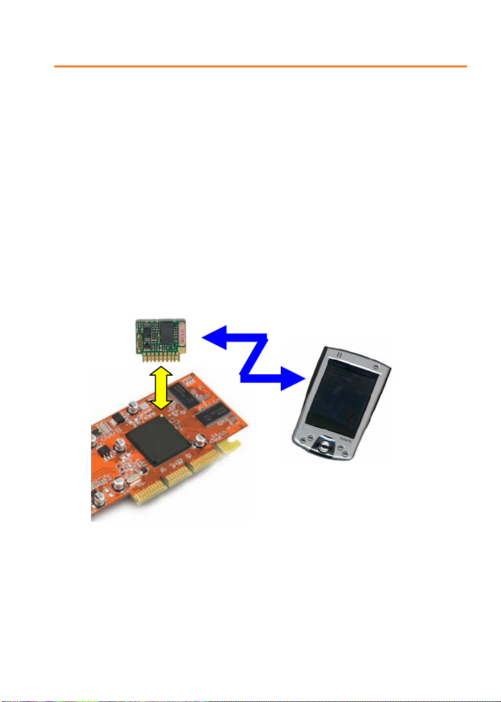
Overview
RF32
The A
over a 20-meter range in the worldwide 2.45 GHz frequency band.
The A
data rate goes up to 723 kbps. Data exchange and set-up are only done
through an UART data port, under SPP profile. A miniature antenna is
integrated.
A
module enables Bluetooth® compliant duplex communications
RF32
module fully complies with the V2.0 Bluetooth® standard and
RF32
can be used in two modes:
Classical Bluetooth® mode : Master starts with GAP identification, then,
SDAP profile review, SPP connection and transparent communication.
Ref. 08-07-V10-ltu
p 6
Page 7

RF32
p
TOP
A
User Guide
Automatic Bluetooth® mode: Identification, profile review and
connection to 1 to 3 known slaves are recorded by the master. After
booting, Bluetooth
RF32
A
modules are available as standalone ARF7044 module or in the
ARF7069 DemoKit. This DemoKit can be fully set-up and used with the
National Semiconductors
®
link is directly open in transparent mode.
®
“Simply Blue Commander” Software.
Hardware essentials
EEPROM
Main Xtal
« Data rate »
jumper
32 kHz Xtal
Integrated
antenna
Bottom Connector
Bluetooth®Chi
Pin-out
All connections are located on the A
Ref. 08-07-V10-ltu
p 7
RF32
bottom connector:
Page 8

RF32
TOP
A
User Guide
VCC = Power Supply
NC = UNUSED
Reset = Full Hardware Reset (active low)
GND = Ground
Uart_cts = « Clear to send » Control Signal In
Uart_tx = « Data to transmit » Data Out
Uart_rx = « Received data » Data In
Uart_rts = « Request to send » Control Signal Out
GND = Ground
GND = Ground
Interface
Pin description
Signal I/O Designation Comment
VCC I Main power supply 2.85 < VCC < 3.6 V and I < 65 mA
NC - Not Connected NOT TO BE USED
Reset I Hardware reset A
Uart_cts I Clear to send Signal Serial port Flow control Input
Uart_tx O Data to transmit Serial port Data Output (0/Vcc level)
Uart_rx I Received data Serial port Data Input (0/Vcc level)
Uart_rts O Request to send
Signal
GND - Common Ground Connected to motherboard ground
Ref. 08-07-V10-ltu
p 8
RF32
reset when Low
(MUST BE USED)
Serial port Flow control Output
(MUST BE USED)
Page 9

RF32
r
TOP
A
User Guide
NOTE
For all I/Os :
Use of the Data Rate Jumper
The purpose of this jumper is to access the A
data rate in case of unknown UART parameters.
Data Rate Jumpe
It becomes possible to re-program the “Non volatile Settings” to access again
the ARF32 Module. When done, jumper can be removed.
0.7 x VCC < Logical 1 < VCC + 0.2 V
- 0.2 V < Logical 0 < 0.25 x VCC
RF32
module by forcing the UART
In case of setup error while evaluating,
communication with ARF32 module can be lost
(bad UART parameters setup).
By connecting the “Data Rate Jumper”, UART
settings are forced to :
• Data rate = 9600 bps
NB : other settings (Parity, Stop bit & Flow
control…) remain the same and have to be
check for recovery values..
Ref. 08-07-V10-ltu
p 9
Page 10

TOP
Footprint
Recommended plugged footprint
Recommended SMD footprint
TOP or
BOTTOM
RF32
A
User Guide
Ref. 08-07-V10-ltu
p 10
Page 11

TOP
Recommended exclusion zone around antenna
For plugged mounting
For SMD mounting
Ground plan
limits
No component
With height >5mm
Antenna
RF32
A
User Guide
Ideally, the module can be placed in edge of the PCB.
Ref. 08-07-V10-ltu
p 11
PCB Edge
Page 12

RF32
TOP
A
User Guide
NOTE
If needed, ARF7044 modules may use a 2-mm pitch connector.
Usable references for mass production are:
- SAMTEC TMM-109-01-LL-S-RA
- RADIOSPARE 132-1083
Standalone ARF7044 module doesn’t include this connector because of the
suggested plugged mounting.
Software management
Non Volatile Default Settings
Parameter Default Value Description
BDADDR HARD CODED Bluetooth® Device Address
Local Name Serial port device
PIN Code 0000 Bluetooth® PIN Code
Operation
Mode
Default
connections
SDP database 1 SPP entry :
UART speed 9600 Speed of the physical UART interface
UART settings 1 Stop bit, parity
Ports to open 0000 0001 Defines the RF Comm port to open
Link keys No link keys Link keys for paired devices
Security mode 2 Security mode
Automatic ON Automatic mode ON or OFF
0 Up to seven default devices to ON or OFF
Name : COM1
Authentif. &
Encrypt. enabled
none
Service discovery database, control for supported
profiles
Settings of the physical UART interface
Ref. 08-07-V10-ltu
p 12
Page 13

RF32
TOP
A
User Guide
Operating modes
There are two main operating modes in the module : command mode and
transparent mode.
The command mode is used to set up the Bluetooth
pieces of Bluetooth
The transparent mode is used to transfer data between two pieces of
Bluetooth
®
®
equipment.
equipment.
Command mode
A specific protocol is used to send commands to the Bluetooth
The frame format is the following :
All the values are in hexadecimal format.
Start
delimiter
1 byte 1 byte 1 byte 2 bytes 1 byte <data
Packet type Operation
code
Data
length
Checksum
Start delimiter: 02 (<STX>)
Packet type : 52 (‘R’ for request), 69 (‘i’ for indication), 43 (‘C’ for confirm)
Operation code : command dependent
Data length : size of data. First byte is the Least Significant Byte and
second byte is the Most Significant Byte
Checksum: Sum of all bytes from the packet type field to the data length
field
Data : command data
End delimite r: 03 (<ETX>)
Example of the inquiry command
Start
delimiter
02 52 00 03 00 55 0A 00
Packet
type
Operation
code
Data
length
Frame : 02 52 00 03 00 55 0A 00 00 03
Ref. 08-07-V10-ltu
p 13
Checksum
®
link between two
®
module.
Data End
length>
bytes
Data End delimiter
00
03
delimiter
1 byte
Page 14

RF32
TOP
A
User Guide
Transparent mode
In this mode all the data received on the UART RX pin are sent by radio to
the target Bluetooth
module UART TX pin.
Mode selection
A specific command (transparent mode) is used in order to switch from
command mode to transparent mode.
A specific pattern : “UART break” is used to switch from transparent mode to
command mode.
Setting up a link using the command interface
Quick start using “Simply Blue Commander” SBC software (*) :
Connect one module with the RS232 link to a PC supporting SBC software.
Setup “SBC Configuration / Transport layer” at the current baudrate (default
9600), 8 bits, 1 stop, no parity, “Low level driver” & “CTS output flow control”
enabled.
Power up the two Bluetooth
< Rx: Event: SimplyBlue Ready, SW Version: 0212
It means Master Module, serial port setup and connection are OK
Open “SBC ARF32 DATA over SPP quick start” commands sub directory.
> Click “BT environment inquiry” & “Send”
< All BT devices nearby send their own BDADDR & Class of Device
(SPP modules class of devices = 000000)
> Click “SPP link establishment”, replace FFs with slave BDADDR & “Send”
In bold : address of the target Bluetooth
< Target module will confirm the connection (State has to be 00)
> Click “Enter SPP transparent mode” & “Send”
< Target module will confirm entering transparent mode (State has to be 00)
You can now close SBC and use any kind of terminal software to exchange
data or files through the Bluetooth SPP link.
(*) : SBC software zip package is downloadable from www.adeunis-rf.com web site.
®
module and will be available on the target Bluetooth®
®
modules. SBC must return:
®
module, discovered during previous step.
Ref. 08-07-V10-ltu
p 14
Page 15

RF32
TOP
A
User Guide
Final use with a PC terminal or a microcontroller
Power up the two Bluetooth
link to a PC or Notebook or PDA. Use a terminal software configured at the
current baudrate (9600 by default), 8 bits, 1 stop, no parity, flow control
material.
Please find below a typical request / response sequence in order to establish
a typical link. All requests must be sending by the PC / NB / PDA (i.e. the
master). All indication and confirm responses are sent by the Bluetooth
slave module:
> GIAC Inquiry request: 02 52 00 03 00 55 0A 00 00 03
< Inquiry module indication: 02 69 01 09 00 73 34 BE 1F 17 00 08 00
In bold : address of the target Bluetooth
command SDAP Connect and the command SPP Connect
< Inquiry module confirm: 02 43 00 01 00 44 00 03
> SDAP connect request: 02 52 32 06 00 8A 34 BE 1F 17 00 08 03
< SDAP connect module confirm: 02 43 32 01 00 76 00 03
> SDAP service browse SPP request: 02 52 35 02 00 89 01 11 03
< SDAP service browse SPP module confirm: 02 43 35 0D 00 85 00 01 02 10 01
> SDAP disconnect request: 02 52 33 00 00 85 03
< SDAP disconnect module confirm: 02 43 33 01 00 77 00 03
> SPP connect request: 02 52 0A 08 00 64 01 34 BE 1F 17 00 08
01 03
< SPP connect module confirm: 02 43 0A 02 00 4F 00 01 03
< SPP connect module indication: 02 69 3E 04 00 AB 01 0C 00 00 03
> Enter transparent mode: 02 52 11 01 00 64 01 03
< Enter transparent mode module confirm: 02 43 11 02 00 56 00 01 03
Now you can exchange data in transparent mode between the two
Bluetooth
To come back to the command mode you have to send an UART break.
®
modules.
®
modules. Connect one module with the RS232
00 00 03
®
module. This address will be used within the
11 01 05 43 4F 4D 31 00 03
®
Ref. 08-07-V10-ltu
p 15
Page 16

TOP
Automatic connection
RF32
A
User Guide
For serial cable replacement the A
automatically to a specific A
automatic connection is done on boot or reset. The A
the link establishment.
In order to do this the following commands have to be entered one time on
RF32
the A
master with for example the “Simply Blue Commander Software:
RF32
RF32
master can be configured to connect
slave and switch to transparent mode. The
RF32
master tries 3 times
> Store default connection request : 02 52 13 0A 00 6F 01 01 01 34 BE 1F 17
< Store default connection confirm 02 43 13 01 00 57 00 03
In bold : address of the target bluetooth module.
> Write operation mode (auto) request : 02 52 4A 01 00 9D 01 03
< Write operation mode confirm 02 43 4A 01 00 8E 00 03
00 08 01 03
Advanced commands
Other commands are available in command mode. Please refer to the
National Semiconductors “Simply Blue Commander Software and “Software
User Guide”
Ref. 08-07-V10-ltu
p 16
Page 17

Specifications
RF32
A
User Guide
Rough data rate 723 Kbps
UART programmable data
rates
UART ports TXD - RXD - RTS – CTS
Frequency FHSS / 2.402 to 2.480 GHz
Radiated RF power 2 mW (3 dBm)
Sensitivity -85 dBm for BER 10-3/ PN9
perating range >20 m when plugged (with exclusion
O
Operating voltage 3.3V nominal (2.85 to 3.6 V)
Transmission current
Connected current
Listen current
Power Down current 250µA
Operating temperature
Dimensions
References :
ARF7044A : Plugged Bluetooth® Class 2 Complete Module
ARF7069B : RS232 Demo Kit
Standards from 9.6 to 921.6 kbps
zone)
40 mA (60mA peak)
< 15mA
5mA
-35°C / +70°C
20 x 24 x 4 mm
Ref. 08-07-V10-ltu p 17
Page 18

TOP
ARF7469 DemoKit schematics
Ref. 08-07-V10-ltu
p 18
RF32
A
User Guide
Page 19

RF32
TOP
A
User Guide
Ref. 08-07-V10-ltu
p 19
 Loading...