

Page 1
Adept MV Controller
User’s Guide
040
SIO
STP
SF
1
OK
2
SCR
A
ESTOP
3
ACC V
C
B
4
SCSI
ON
VME
D
2
3
41
OK
6
7
D
85
R
I
RESET
V
E
A
F
P
/
ABORT
M
C
P
RESET
R
R
R
S
S
S
2
4
2
3
2
3
2
2
2
#1
R
S
2
I
3
/
2
O
R
2
S
4
2
V
3
E
2
T
1
/
®
DIO
FAIL PASS
I
I
T
T
S
NPU
HPE
DE1
DE2
MI6
ESF1F2F3F4
OK
ESTOP
SIO
123
STP
SCRCVME
040
ABD
SF
NPU
DE3
DE4
DE5
DE6
E
N
CODER
F5
F6
I
V
E
D
R
A
ACC V
SCSI
OK
RESET
6785ON2341
4
F
ABORT
T
T
P
U
U
O
S
A
E
C
HIN
M
232
S
R
232
S
R
/
P
P
C
M
RESET
422
S
R
T
T
S
S
P
U
U
O
S
ERV
O
232
S
R
T
T
E
E
HER
N
WARNING:
FOR CONTINUED PROTECTION AGAINST RISK OF FIRE,
A
m
T
E
R
#2
M
REPLACE ONLY WITH SAME TYPE AND RATING OF FUSE.
USE ONLY WITH
250V FUSES
~100-240V
50/60HZ
5AT
I
/
2
4V100
O
#1
/
232
S
R
H
0
T
E
0
E
R
m
R
N
A
M
E
T
#2
USE ONLY WITH
WARNING:
250V FUSES
FOR CONTINUED PROTECTION
AGAINST RISK OF FIRE,
REPLACE ONLY WITH SAME
TYPE AND RATING OF FUSE.
5AT
~100-240V
50/60HZ
VJI
VGB
VIS
DIO
FAIL PASS
HPE
ES
OK
2
1
4
3
V
V
6
5
I
D
E
O
B
U
S
M
O
N
I
T
O
R
2
3
41
P
O
I
N
T
E
R
KEYBOARD
I
I
N
D
P
E
U
O
T
S
B
U
S
I
N
P
U
T
S
AMPLIFIER
SIGNAL
1
2
3
4
O
ON
U
T
P
U
T
BELT
S
ENCODER
C
A
M
O
E
U
R
T
A
P
S
U
/
T
S
S
T
R
O
B
ARM
E
SIGNAL
S
®
Page 2

Page 3
Adept MV Controller
User’s Guide
DIO
FAIL PASS
I
I
T
T
S
NPU
HPE
DE1
DE2
MI6
ESF1F2F3F4
OK
ESTOP
SIO
123
STP
SCRCVME
040
ABD
SF
NPU
DE3
DE4
DE5
DE6
E
N
CODER
F5
F6
I
V
E
D
R
A
ACC V
SCSI
OK
RESET
6785ON2341
4
F
ABORT
T
T
P
U
U
O
S
A
E
C
HIN
M
232
S
R
232
S
R
/
P
P
C
M
RESET
422
S
R
T
T
S
S
P
U
U
O
S
ERV
O
232
S
R
T
T
E
E
HER
N
I
/
2
4V100
A
O
m
#1
#2
/
232
T
S
E
R
R
M
Part Number 00330-01030, Rev C
September 1996
®
WARNING:
FOR CONTINUED PROTECTION AGAINST RISK OF FIRE,
REPLACE ONLY WITH SAME TYPE AND RATING OF FUSE.
USE ONLY WITH
250V FUSES
~100-240V
50/60HZ
5AT
040
SIO
STP
SF
1
OK
2
SCR
A
ESTOP
3
ACC V
C
B
4
SCSI
ON
VME
D
2
3
41
OK
6
7
D
85
R
I
RESET
V
E
A
F
P
/
ABORT
M
C
P
RESET
R
R
R
S
S
S
2
4
2
3
2
3
2
2
2
#1
R
S
2
I
3
/
2
O
R
2
S
4
2
V
3
E
2
T
1
/
H
0
T
E
0
E
R
m
R
N
A
M
E
T
#2
VJI
VGB
VIS
DIO
FAIL PASS
HPE
ES
OK
2
1
4
3
V
V
6
5
I
D
E
O
B
U
S
M
O
N
I
T
O
R
2
3
41
P
O
I
N
T
E
R
KEYBOARD
I
I
N
D
P
E
U
O
T
S
B
U
S
I
N
P
U
T
S
AMPLIFIER
SIGNAL
1
2
3
4
O
ON
U
T
P
U
T
BELT
S
ENCODER
C
A
M
O
E
U
R
T
A
P
S
U
/
T
S
S
T
R
O
B
ARM
E
SIGNAL
S
®
USE ONLY WITH
WARNING:
250V FUSES
FOR CONTINUED PROTECTION
AGAINST RISK OF FIRE,
REPLACE ONLY WITH SAME
TYPE AND RATING OF FUSE.
5AT
~100-240V
50/60HZ
adept
c
te hnology, inc.
®
150 Rose Orchard Way • San Jose, CA 95134 • USA • Phone (408) 432-0888 • Fax (408) 432-8707
Otto-Hahn-Strasse 23 • 44227 Dortmund • Germany • Phone 0231/75 89 40 • Fax 0231/75 89 450
41, rue du Saule Trapu • 91882 • Massy cedex • France • Phone (33) 01.69.19.16.16 • Fax (33) 01.69.32.04.62
Via don Luigi Sturzo 39/41 • 52100 Arezzo • Italy • Phone 575.3986 11 • Fax 575.3986 20
1-2, Aza Nakahara Mitsuya-Cho • Toyohashi, Aichi-Ken • 441-31 • Japan • (0532) 65-2391 • Fax (0532) 65-2390
Page 4

The information contained herein is the property of Adept Technology, Inc. and shall not be reproduced in whole or in part without prior written approval of Adept Technology, Inc. The information her e in is subject to ch ange without notice and should not be constru e d as a commitment b y
Adept Technolo gy, Inc. This manual is perio di cally rev ie wed and revis ed.
Adept Technology, Inc. assumes no responsibility for any errors or omissions in this
document. Critical evaluation of this manual by the user is welcomed. Your comments
assist u s in prepar atio n of futu re docu mentati on. A for m is prov ided at t he back of the book for su bmitting your comments.
Copyright © 1993, 1994, 1995, 1996 by Adept Technology, Inc. All rights reserved.
The Adept logo is a registered trademark of Adept Technology, Inc.
Adept, AdeptOne, AdeptOne-MV, AdeptThree, AdeptThree-MV, PackOne, PackOne-MV,
HyperDrive, Adept 550, Adept 550 CleanRoom, Adept 1850, Adept 1850XP,
A-Series, S-Series, Adept MC, Adept CC, Adept IC, Adept OC, Adept MV,
AdeptVision, AIM, VisionWare, AdeptMotion, MotionWare, P a lletWare,
AdeptNet, AdeptFTP, AdeptNFS, AdeptTCP/IP, AdeptForce, AdeptModules,
and V
+
are trademarks of Adept Technology, Inc.
Any trademarks from other companies used in this publication
are the property of those respective companies.
Printed in the United States of America
Page 5
DECLARATION OF CONFORMITY
We, Adept Technology, with Corporate Headquarters at 150 Rose Orchard Way, San Jose, CA.,
USA, and European Technical Center at Otto-Hahn Str. 23, 44227 Dortmund, Germany,
here with declare that the:
Controllers MV-5 (P /N 30340-10000 and 30340-30000), MV-8 (P/N 30330-15000),
MV-10 (P/N 30340-20000 and 30340-40000) or MV-19 (P/ N 30330-25000),
with/without
Operator’s Manual Control Pendant (MCP III) (P/N 90332-48050)
VME Front Panel Category 1 (P/N90332-00380) or Category 3 (P/N 90335-00380)
in the form delivered by us to which this Declaration relates, comply with the relevant and
fundamental safety and health requirements defi ned in the EC Directiv e 89/336/EEC,
Appendix 1, and the following standards:
EN 55011: 1991, Class A
EN 50082-2: 1995
EN 60204-1: 1992
IEC 1131-2: 1992
following the provision of Directives:
89/336/EEC
89/392/EEC
73/23/EEC
under the following usage and environmental conditions:
1. The Controller must not be put into operation until all of the machinery into wh ich it is
incorporated has been declared in compliance with the provisions of the effect ive versions of
the directives. This includes all supplementary equipment and protective devices.
2. The Controller must be used in accordance with instru ctions specified in the Adept MV
Controller Instruction Handbook.
3. The Controller must incorporate only those MV Plug-in Modules listed in Table 1 or Table 2
attached. If Plug-in Modules listed in Table 2 are installed, the user must verify conformance to
the EMC Directive after installation.
4. This Declaration applies only to those Adept product part-numbers specifically listed in this
declaration. The following changes may result in the system not complying with the applicable
Directives, and would void this declaration unless additional testing and/or evaluation is
performed by the user:
• unauthorized user-modifications;
• substitution or addition of Adept parts n ot listed on this declaration;
• addition of u s e r-s u p p li e d p a rt s a n d accessorie s
This Declaration is based upon extensive tests and evaluati on by TÜV Rheinland, a Notified and
Competent Body, in their Project Numbers E937204 3 and E9572482. The complete Fi l e i s available at
Adept’s California addr ess.
Place: San Jose, California, USA
Date: 18 September 1996
Signed:
Full Name: Richard J. Casler, Jr.
Position: Vice President, Engineering
P/N 0133 2-0 0050
Rev. A-X1
Page 6

English
Declaration of Conformity
as defined in Machinery Directive 89/392/EEC, Appendix IIB
We herewith declare that the machine as delivered by us complies with the
relevant and fundamental safety and health requirements defined in the EC
Directive, Appendix 1.
Deutsch
Konformitätserklärung
im Sinne der EG-Maschinenrichtlinie 89-392/EWG, Anhang II B
Hiermit erklären wir, daß die nachstehende Maschine in der von uns gelieferten
Ausführung, den einschlägigen , grundleg en de n S ic h erheits- u n d
Gesundheitsanforderungen der EG-Richlinie Anhang I, entspricht.
Française
Déclaration de Conformité,
selon la Directive Communautaire relative aux machines
89/392/CEE, Annexe II B.
Par la présente, mnous déclarons que la machine décrite ci-dessous, livrée en
l'état, est conforme à la directive communautaire, Annexe I, sur les impératifs
fondamentaux en matière de santé et de sécurité.
Italiano
Dichiarazione di Conformità
ai sensi della direttiva CE 89/392/EEC relativa a macchinari Appendice IIB
Si dichia ra c h e la m acchina , com e da n oi fornita, soddisf a i requisiti fondam e n t a li
definiti nella direttiva CE, Appendice I,in fatto di sicurezza e sanità.
P/N 0133 2-0 0050
Rev. A-X1
Page 7
Table 1
VME Plug-in Modules and accessories that meet all applicable Directives and that may be
installed , with ou t ad d itio n al EM C co nfo r man ce testing, in MV-5, MV-8, MV-1 0, and MV-19
Controllers
Part Nu mber
Minimum Acceptable
Revision
Description
10332-11150 P6 PCA, VME 030 Processor
10332-00710 P1 PCA, VME 040 Processor
30332-12350 P2 SYSIO 2 Module Assy FD/HD (SIO2)
30332-12351 P2 SYSIO 2 Module Assy FD
10332-00800 P2 PCA, VME Digital I/O (DIO)
10332-10250 P3 PCA, VME Graphics Board (VGBIII)
10332-00600 P2 PCA VME Frame Grabber (VIS)
10332-00655 P1 PCA VME Frame Grabber (EVI)
10332-11400 P4 PCA, VME Motion Interface, MI-3
10332-12400 P2 PCA, VME Motion Interface, MI-6
10332-00500 P2 PCA, VME Joint Interface (VJI III)
15600-00090 A Camera, CCD
Table 2
Plug-in Modules and Accessories that may be installed in MV-5, MV-8, MV-10, and MV-19
Controllers but must first be tested in the final system configurati on to assure full
compliance.
Part Number Minimum Acceptable
Revision
90332-02020 P1 AdeptNet 10BaseT Kit
10330-00970 B PCA, VME Analog I/O (AIO)
90211-00000 B Adept Force Kit
90332-12400 A MP6 Kit
Description
P/N 0133 2-0 0050
Rev. A-X1
Page 8

Page 9

Table of Contents
Introduction . . . . . . . . . . . . . . . . . . . . . . . . . . . . . . . . . . 1
1
1.1 How to Use This Ma n u al
Follow These Steps to Install and Configure the Adept MV Controller
Related Manuals
Standard Manuals
Other Adept Pro duct M a nuals
Optional V
1.2 Warnings, Cautio ns, and Notes
1.3 Safety
1.4 Standards Compliance
1.5 How Can I Get Help?
. . . . . . . . . . . . . . . . . . . . . . . . . . . . . . . . . .
Reading and Tr aini ng for Us e rs and Ope rator s
Syste m Safe guards
Safety Features on External VME Front Panel (VFP)
Computer-C on tro lled Robo ts and Motion Device s
Manually-Co ntr oll ed Robots and Motion D evic es
Other Computer-Controlled Devices
Progr a m S e curity
Overspeed Protection
Voltage Interrup tion s
Inappropriate Uses of the Adept MV Controller
. . . . . . . . . . . . . . . . . . . . . . . . . .
. . . . . . . . . . . . . . . . . . . . . . . . . . .
+
Develop e r’s M an ual s
. . . . . . . . . . . . . . . . . . . . . . . . . .
. . . . . . . . . . . . . . . . . . . . . . . . . . .
. . . . . . . . . . . . . . . . . . . . . . . . .
. . . . . . . . . . . . . . . . . . . . . . . . .
. . . . . . . . . . . . . . . . . . . . . . . . . .
. . . . . . . . . . . . . . . . . . . . . . . . . . .
. .
. . . . . . . . . . . . . . . . . . . . . . .
. . . . . . . . . . . . . . . . .
. . . . . . . . . . . . . . .
. . . . . . . . . . . . . . . . . . . . . .
. . . . . . . . . . . . .
. . . . . . .
. . . . . . .
. . . . . . . .
. . . . . . . . . . . . . .
. . . . . . . . . . . .
2
2
2
2
3
3
4
4
4
5
5
5
5
5
6
6
6
6
7
8
Within the Continental United States
Servic e Calls
Application Questions
Training Information
Within Europe
Outside Continental United States or Europe
Adept World Wide Web Site
Adept Bulletin Board Service
Overview . . . . . . . . . . . . . . . . . . . . . . . . . . . . . . . . . . . 11
2
2.1 Introduction
2.2 Controller Models
Adept MV-5 Controller
Adept MV-10 Controller
Adept MV-8 Controller
Adept MV-19 Controller
2.3 A-Series and S-Series Controller Options
. . . . . . . . . . . . . . . . . . . . . . . . . . . . . .
. . . . . . . . . . . . . . . . . . . . . . . . . . . .
. . . . . . . . . . . . . . . . . . . . . . . . . .
. . . . . . . . . . . . . . . . . . . . .
. . . . . . . . . . . . . . . . . . . . . .
. . . . . . . . . . . . . . . . . . . . . . . . . . . . .
. . . . . . . . . . . . . . . . . . . . . .
. . . . . . . . . . . . . . . . . . . . . .
. . . . . . . . . . . . . . . . . . . . . . . .
. . . . . . . . . . . . . . . . . . . . . . .
. . . . . . . . . . . . . . . . . . . . . . . .
. . . . . . . . . . . . . . . . . . . . . . .
. . . . . . . . . . . . . . . . . .
. . . . . . . . . . . . . .
. . . . . . . . . . . . . . . .
Adept MV Controller User’s Guide, Rev C vii
8
8
8
8
9
9
9
9
12
12
12
12
14
14
14
Page 10

Table Of Contents
Adept A-Series Option
Adept S-Series Option
2.4 Standard Modules
. . . . . . . . . . . . . . . . . . . . . . . . . . .
System Processor (030 or 040)
030 Module
040 Module
System Input/ Output Module (SIO)
2.5 Optional Modules
. . . . . . . . . . . . . . . . . . . . . . . . . . .
Adept Grap hi c s M odule (VGB)
AdeptVision VM E Inter fac e M od ul e (VIS)
AdeptMoti on In terfa c e Mod ule s (MI3/MI6)
Adept VME Joint Interfac e Mod ul e (VJI)
AdeptForce VME Mo d u le (VFI)
Digital Input/ Output Module (DI O )
Auxiliary Processor
2.6 Optional Equipment
External Front Panel (V FP-1 or VFP-3)
Manual Control Pendant (MCP)
AdeptNet
. . . . . . . . . . . . . . . . . . . . . . . . . . . . . . .
A-Series Color Monitor
A-Series Extended Keyboard
Third-Party Terminals for an S-Series Controller
2.7 Product Descriptions
. . . . . . . . . . . . . . . . . . . . . . . .
. . . . . . . . . . . . . . . . . . . . . . . . .
. . . . . . . . . . . . . . . . . . . . .
. . . . . . . . . . . . . . . . . . . . . . . . . .
. . . . . . . . . . . . . . . . . . . . . . . . . .
. . . . . . . . . . . . . . . . . .
. . . . . . . . . . . . . . . . . . . .
. . . . . . . . . . . . . . .
. . . . . . . . . . . . . .
. . . . . . . . . . . . . . . .
. . . . . . . . . . . . . . . . . . . .
. . . . . . . . . . . . . . . . . .
. . . . . . . . . . . . . . . . . . . . . . . . . .
. . . . . . . . . . . . . . . . . . . . . . . . . .
. . . . . . . . . . . . . . . . . .
. . . . . . . . . . . . . . . . . . . .
. . . . . . . . . . . . . . . . . . . . . . . . .
. . . . . . . . . . . . . . . . . . . . .
. . . . . . . . . . . . .
. . . . . . . . . . . . . . . . . . . . . . . . . .
14
15
15
15
15
15
15
16
16
16
16
18
18
18
18
19
19
19
19
19
19
20
20
AdeptVision VME
AdeptMotion VME
AdeptForce VME
3
Installation for MV-5 and MV-10 Controllers
. . . . . . . . . . . . . . . . . . . . . . . . . . .
. . . . . . . . . . . . . . . . . . . . . . . . . .
. . . . . . . . . . . . . . . . . . . . . . . . . . .
3.1 Shipping, Storage, Unpacking and I n s pection
Shipping an d S torage
Before Unpacking
Upon Unpackin g
Repacking For Relocation
3.2 Controller ID Label
. . . . . . . . . . . . . . . . . . . . . . . . . . .
3.3 Facility Requirements
Voltage Interrup tion s
. . . . . . . . . . . . . . . . . . . . . . . . .
. . . . . . . . . . . . . . . . . . . . . . . . . . .
. . . . . . . . . . . . . . . . . . . . . . . . . . .
. . . . . . . . . . . . . . . . . . . . . . .
. . . . . . . . . . . . . . . . . . . . . . . . . .
. . . . . . . . . . . . . . . . . . . . . . . . .
3.4 Connecting AC Power (MV-5 an d MV-10)
AC Power Requirements
. . . . . . . . . . . . . . . . . . . . . . .
Facility Overvoltage Protection
Power Ent r y M o d u le
. . . . . . . . . . . . . . . . . . . . . . . . . .
Function of VFP System Power Switch with MV-5 and MV-10 Controllers
Remote System Power Option
Connecting AC Power Cord
. . . . . . . . . . . . . .
. . . . . . . . . . . . .
. . . . . . . . . . . . . . .
. . . . . . . . . . . . . . . .
. . . . . . . . . . . . . . . . .
. . . . . . . . . . . . . . . . . . . . .
21
20
20
20
22
22
22
22
22
22
23
23
24
24
24
25
25
25
27
viii Adep t MV Controller User’s Guide, Rev C
Page 11

Table Of Contents
System Grounding Information
3.5 Fuse Informatio n (MV -5 a n d MV-10)
3.6 Fan and Filter Informa tion
Cooling Fan
. . . . . . . . . . . . . . . . . . . . . . . . . . . . .
. . . . . . . . . . . . . . . . . . . . . . . .
Filter Inspection and Cleaning
3.7 Removing and Installin g Modules
VMEbus Addres s Setti ng s
Upper Backplane Jum per Plugs (P1 )
. . . . . . . . . . . . . . . . . . . .
. . . . . . . . . . . . . . . . . .
. . . . . . . . . . . . . . . . . . . .
. . . . . . . . . . . . . . . . . . . .
. . . . . . . . . . . . . . . . . . . . . .
. . . . . . . . . . . . . . . . .
Lower Backplane Jumper Plugs (P2) and Third-Party Modules
Removing Modul es
Installing Modules
3.8 Installing the A-Series Monit or and Keyboar d
Installation Procedure
. . . . . . . . . . . . . . . . . . . . . . . . .
. . . . . . . . . . . . . . . . . . . . . . . . . .
. . . . . . . . . . . . . .
. . . . . . . . . . . . . . . . . . . . . . . .
Installing Non -Ad ept Peripheral s in an A-S erie s Syst e m
Third-P arty Mon ito r Compat ibility
Third-P a r ty Ke yboard Comp atibility
. . . . . . . . . . . . . . .
. . . . . . . . . . . . . .
Third-P arty Pointing Dev ic e Compa tibility
3.9 Installing a Terminal in an S-Se rie s S yst em
Recommended Terminal for S-Series Systems
Cont acting W Y S E
. . . . . . . . . . . . . . . . . . . . . . .
Customer-S upp lied Serial Interfa c e Ca ble
Installation Procedure
. . . . . . . . . . . . . . . . . . . . . . . .
. . . . . . . . . . . . . . . .
. . . . . . . . . . . .
. . . . . . . . . . . . . .
3.10 Installing a Stand-A lone Controller in a Rack o r Pan e l
. . . .
. . . . . . . .
. . . . . . . . . . .
. . . . . . . . .
28
28
29
29
29
30
30
30
31
33
33
34
34
35
35
35
35
36
36
36
36
36
37
Space Around the Ch assi s
Rack Mounti ng
Panel Mounting
. . . . . . . . . . . . . . . . . . . . . . . . . . .
. . . . . . . . . . . . . . . . . . . . . . . . . . .
. . . . . . . . . . . . . . . . . . . . . .
3.11 Installing a Robot Controller in a Rack or Panel
Space Around the Ch assi s
Rack Mounti ng
Panel Mounting
. . . . . . . . . . . . . . . . . . . . . . . . . . .
. . . . . . . . . . . . . . . . . . . . . . . . . . .
. . . . . . . . . . . . . . . . . . . . . .
3.12 MV-5 and MV-10 Controller Technical Speci fications
4
Installation for MV-8 and MV-19 Controllers
4.1 Shipping, Storage, Unpacking and I n s pection
Shipping an d S torage
Before Unpacking
Upon Unpackin g
Repacking For Relocation
4.2 Controller ID Label
. . . . . . . . . . . . . . . . . . . . . . . . . . .
4.3 Facility Requirements
Voltage Interrup tion s
4.4 Connecting AC Po we r
. . . . . . . . . . . . . . . . . . . . . . . .
. . . . . . . . . . . . . . . . . . . . . . . . . .
. . . . . . . . . . . . . . . . . . . . . . . . . .
. . . . . . . . . . . . . . . . . . . . . .
. . . . . . . . . . . . . . . . . . . . . . . . . .
. . . . . . . . . . . . . . . . . . . . . . . .
. . . . . . . . . . . . . . . . . . . . . . . . .
. . . . . . . . . . . .
. . . . . . . . .
. . . . . . . . . . . . . .
. . . . . . . . . . . . . .
37
37
38
39
39
39
39
41
43
44
44
44
44
44
44
45
45
46
Adept MV Controller User’s Guide, Rev C ix
Page 12

Table Of Contents
AC Power Requirements
Facility Overvoltage Protection
Power Ent r y M o d u le
Connecting AC Power Cord
System Grounding Information
Changin g Voltage Settings (M V-8 and MV-19 )
4.5 Fuse Informatio n (MV -8 a n d MV-19)
4.6 Fan and Filter Informa tion
Cooling Fan
. . . . . . . . . . . . . . . . . . . . . . . . . . . . . .
Filter Inspection and Cleaning
4.7 Removing and Installin g Modules
VMEbus Addres s Setti ng s
Backplane Jumper Plugs
Removing Modul es
Installing Modules
. . . . . . . . . . . . . . . . . . . . . . . . . . .
4.8 Installing the A-Ser ies Monitor and K e ybo ard
4.9 Installing a Terminal in an S-Se rie s S yst em
4.10 Installing in a Rack or Pa nel Mo u nt
Space Around the Ch assi s
Panel Mounting
Rack Mounti ng
. . . . . . . . . . . . . . . . . . . . . . . . . . . .
. . . . . . . . . . . . . . . . . . . . . . . . . . . .
. . . . . . . . . . . . . . . . . . . . . . .
. . . . . . . . . . . . . . . .
. . . . . . . . . . . . . . . . . . . . . . . . . .
. . . . . . . . . . . . . . . . . . . . .
. . . . . . . . . . . . . . . . . . . .
. . . . . . . . . . . .
. . . . . . . . . . . . . . . . . .
. . . . . . . . . . . . . . . . . . . . . . .
. . . . . . . . . . . . . . . . . . . . .
. . . . . . . . . . . . . . . . . . .
. . . . . . . . . . . . . . . . . . . . . . .
. . . . . . . . . . . . . . . . . . . . . . .
. . . . . . . . . . . . . . . . . . . . . . . . . .
. . . . . . . . . . . . . .
. . . . . . . . . . . . . . .
. . . . . . . . . . . . . . . . . .
. . . . . . . . . . . . . . . . . . . . . .
4.11 MV-8 and MV-19 Controller Technical Speci fications
. . . . . . . . .
46
46
47
47
48
48
50
51
51
51
52
52
52
54
54
54
54
55
55
55
55
57
5
030 Processor Module
5.1 Introduction
5.2 Connections and Indicators
5.3 Serial I/O Connections, 030 Mo dule
RS-422/485 Connector (on 030 Module)
RS-232/Term Connector (on 030 Module)
5.4 Memory
. . . . . . . . . . . . . . . . . . . . . . . . . . . . . . . .
5.5 VMEbus Address
5.6 030 Jumper Settings
5.7 Use as an Auxiliary Pro ce ssor
. . . . . . . . . . . . . . . . . . . . . . . . . . .
. . . . . . . . . . . . . . . . . . . . . . . . . . . . . .
. . . . . . . . . . . . . . . . . . . . . .
. . . . . . . . . . . . . . . . . .
. . . . . . . . . . . . . . . .
. . . . . . . . . . . . . . .
Used in an S-Series System
Used in an A-Series System
Typical Cable Co nne cti o n s
Typical Cabl e Co nnec ti o n s, 9- pin to 25-pin (DCE)
Typical Cabl e Co nnec ti o n s, 9- pin to 25-pin (DTE)
. . . . . . . . . . . . . . . . . . .
. . . . . . . . . . . . . . . . . . .
. . . . . . . . . . . . . . . . . .
. . . . . . .
. . . . . . . .
Recommended Connections, 9-pin to 25-pin (Wyse WY-60 Terminal)
. . . . . . . . . . . . . . . . . . . . . . . . . . . . . .
Typical Cabl e Co nnec ti o n s, 9- pin to 9-p in (A T -Co m patible)
DTE, DCE, or AT-style?
. . . . . . . . . . . . . . . . . . . . . . . . . . . .
. . . . . . . . . . . . . . . . . . . . . . . . . .
. . . . . . . . . . . . . . . . . . . . .
. . . . . . . . . . . . . . . . . . . . . .
. .
59
60
60
61
61
62
62
62
63
63
64
64
65
66
67
67
68
69
x Adept MV Controller User’s Guide, Rev C
Page 13

Table Of Contents
5.8 030 Processo r Mod u l e Specifi cations
6
040 Processor Module
6.1 Introduction
. . . . . . . . . . . . . . . . . . . . . . . . . . . . . .
. . . . . . . . . . . . . . . . . . . . . . . . . . .
6.2 Connections and Indicators
6.3 Serial I/O Connections, 040 Mo dule
RS-422 Connector (on 040 Module)
RS-232/Term Connector (on 040 Module)
Used in an S-Series System
Used in an A-Series System
Connections from 040 RS-232 to Wyse Terminal
6.4 Memory
6.5 VMEbus Address
6.6 040 Jumper Settings
. . . . . . . . . . . . . . . . . . . . . . . . . . . . . . . .
. . . . . . . . . . . . . . . . . . . . . . . . . . . .
. . . . . . . . . . . . . . . . . . . . . . . . . .
6.7 Use as an Auxiliary Pro ce ssor
6.8 040 Processo r Mod u l e Specifi cations
7
System Input/Output Module (SIO)
. . . . . . . . . . . . . . . . . .
. . . . . . . . . . . . . . . . . . . . . .
. . . . . . . . . . . . . . . . . . .
. . . . . . . . . . . . . . . . .
. . . . . . . . . . . . . .
. . . . . . . . . . . . . . . . . .
. . . . . . . . . . . . . . . . . .
. . . . . . . .
. . . . . . . . . . . . . . . . . . . . . .
. . . . . . . . . . . . . . . . . .
. . . . . . . . . . . . . . . . . . .
69
71
72
72
73
73
74
74
74
76
76
77
77
79
79
81
7.1 Introduction
7.2 Connections and Indicators
DIP Switch Setting s
. . . . . . . . . . . . . . . . . . . . . . . . . . . . . .
. . . . . . . . . . . . . . . . . . . . . .
. . . . . . . . . . . . . . . . . . . . . . . . . .
7.3 System Configuration Information
7.4 Mass Storage
Floppy Drive
Hard Drive
7.5 Serial I/O Connectors
7.6 Digital I/O Connecto r
Input Signals
. . . . . . . . . . . . . . . . . . . . . . . . . . . . . .
. . . . . . . . . . . . . . . . . . . . . . . . . . . . .
. . . . . . . . . . . . . . . . . . . . . . . . . . . . . .
. . . . . . . . . . . . . . . . . . . . . . . . . .
. . . . . . . . . . . . . . . . . . . . . . . . . .
. . . . . . . . . . . . . . . . . . . . . . . . . . . . .
REACT Input Signals 1001 to 1012
Fast Input Signals 1001 to 1003
Output Signals
Typica l D ig ital Inpu t Wiring
. . . . . . . . . . . . . . . . . . . . . . . . . . . .
. . . . . . . . . . . . . . . . . . . . . .
Typical D ig ital Outp ut W iring
Digital I/O Connec to r Pinouts
Digital I/O Con nec to r Ord e ring De tai ls (T hi rd-P a rty Sourc es)
AMP Part Numbers for 50-Pin Male D-Sub
Thomas and Betts Part Numbers for 50-Pin Male D-Sub
Screw-Terminal Field-Wiring Adaptor Blocks
7.7 Emergency Stop Ci rcuit
. . . . . . . . . . . . . . . . . . . . . . . . .
. . . . . . . . . . . . . . . . . . . .
. . . . . . . . . . . . . . .
. . . . . . . . . . . . . . . .
. . . . . . . . . . . . . . . . . . . . .
. . . . . . . . . . . . . . . . . . . .
. . . . .
. . . . . . . . . . .
. . . .
. . . . . . . . . . . . .
82
82
83
83
83
83
83
84
85
85
85
85
87
88
89
90
91
91
92
92
93
External E-Stop In put
Passive E-Stop Output
Adept MV Controller User’s Guide, Rev C xi
. . . . . . . . . . . . . . . . . . . . . . . . .
. . . . . . . . . . . . . . . . . . . . . . . .
93
93
Page 14

Table Of Contents
7.8 External Front Panel (V F P-1 )
Controls and Indicators
Installing the External Front Panel (VFP)
7.9 Manual Control Pendant (MCP)
Connecting the MCP to the VFP
MCP Cradle
7.10 User-Supplied External Front Panel
Construction of Cable from SIO to VFP
MCP Connecto r
Front Panel/MC P Con ne c to r and Ca bl e
7.11 SIO Module Specific at ions
8
Adept Graphics Module (VGB)
8.1 Introduction
8.2 Connections and Indicators
DIP Switch Setting s
8.3 VMEbus Address
8.4 Monitor Video Interface
. . . . . . . . . . . . . . . . . . . . . . . . . . . . . .
. . . . . . . . . . . . . . . . . . . . . . . . . . . .
. . . . . . . . . . . . . . . . . . . . . .
. . . . . . . . . . . . . . . . . . . . . . . .
. . . . . . . . . . . . . . . .
. . . . . . . . . . . . . . . . . . . . .
. . . . . . . . . . . . . . . . . . .
. . . . . . . . . . . . . . . . . . . . . . . . . .
. . . . . . . . . . . . . . . . . .
. . . . . . . . . . . . . . .
. . . . . . . . . . . . . . . . . . . . . . . . . .
. . . . . . . . . . . . . .
. . . . . . . . . . . . . . . . . . . . . .
. . . . . . . . . . . . . . . . . . . . .
. . . . . . . . . . . . . . . . . . . . . .
. . . . . . . . . . . . . . . . . . . . . . . . .
. . . . . . . . . . . . . . . . . . . . . . . .
96
96
97
99
99
99
100
100
100
101
102
103
104
104
105
105
106
8.5 Keyboard Interface
8.6 Pointer Interface
8.7 VGB Module Specifica tion s
9
AdeptVision VME Module (VIS)
9.1 Introduction
9.2 Connections and Indicators
9.3 VMEbus Address and Conf iguration
9.4 Camera Comp at ibilit y
9.5 Installing Video Bus Cou pling
9.6 Camera Breakout Cables
Two-Camera Brea ko ut Cable
Four-Camera Breakout Cable
10-Meter Adept MV Camera Cables
9.7 Installing Camera C ab l es
9.8 Camera Cable Pin and Signal Information
9.9 VIS Module Specificat ions
. . . . . . . . . . . . . . . . . . . . . . . . . . . .
. . . . . . . . . . . . . . . . . . . . . . . . . . . . . .
. . . . . . . . . . . . . . . . . . . . . . . . . .
. . . . . . . . . . . . . . . . . . . . . . .
. . . . . . . . . . . . . . . . . . . . . .
. . . . . . . . . . . . . . . . . . . . . .
. . . . . . . . . . . . . . . . . .
. . . . . . . . . . . . . . . . . . . . . . . . .
. . . . . . . . . . . . . . . . . . . . . .
. . . . . . . . . . . . . . . . . . . . . . .
. . . . . . . . . . . . . . . . . . . .
. . . . . . . . . . . . . . . . . . . .
. . . . . . . . . . . . . . . .
. . . . . . . . . . . . . . . . . . . . . . .
. . . . . . . . . . . . . . .
. . . . . . . . . . . . . . . . . . . . . . .
107
107
108
109
110
110
111
112
113
113
113
114
114
115
116
124
10
AdeptMotion Interface Module (MI6/MI3)
10.1 Introduction
10.2 Connections and Indicators
. . . . . . . . . . . . . . . . . . . . . . . . . . . . . .
. . . . . . . . . . . . . . . . . . . . . .
. . . . . . . . . . . . . .
xii Adept MV Controller User’s Guide, Rev C
125
126
126
Page 15

Table Of Contents
11
12
10.3 VMEbus Address
10.4 Jumper Settings and Resistor Configuration on MI3/MI6
10.5 Connecting to User Equipment
10.6 MI3/MI6 Module Sp e cifications
Adept Joint Interface Module(VJI)
11.1 Introduction
11.2 Connections and Indicators
11.3 VMEbus Address
Address Setting s for VJI Modules
Addre ss Settings fo r M ultiple Se r v o B o ards
11.4 Belt E n coder In terface
11.5 VJI Module Specificatio ns
AdeptForce VME Module (VFI)
12.1 Introduction
12.2 Connections and Indicators
. . . . . . . . . . . . . . . . . . . . . . . . . . . .
. . . . . . . . . . . . . . . . . . . .
. . . . . . . . . . . . . . . . . . . .
. . . . . . . . . . . . . . . . .
. . . . . . . . . . . . . . . . . . . . . . . . . . . . . .
. . . . . . . . . . . . . . . . . . . . . .
. . . . . . . . . . . . . . . . . . . . . . . . . . . .
. . . . . . . . . . . . . . . . . . .
. . . . . . . . . . . . . .
. . . . . . . . . . . . . . . . . . . . . . . . .
. . . . . . . . . . . . . . . . . . . . . . .
. . . . . . . . . . . . . . . . . . . .
. . . . . . . . . . . . . . . . . . . . . . . . . . . . . .
. . . . . . . . . . . . . . . . . . . . . .
. . . . . . . .
127
127
128
129
131
132
132
133
133
133
134
136
137
138
138
13
12.3 VMEbus Address
12.4 VFI Module Specificatio ns
. . . . . . . . . . . . . . . . . . . . . . . . . . . .
. . . . . . . . . . . . . . . . . . . . . . .
Digital Input/Output Module (DIO)
13.1 Introduction
13.2 Connections and Indicators
13.3 Inputs
13.4 Outputs
Testing Outputs and Fuses
Output Power Suppl y Volta g e Jum per s
Output Power Sup pl y Cu rre nt Se lec tio n
13.5 Typical DIO Wiring
13.6 Optional DIO Cables
Labeling Ca bl es
Input and Outp ut C ab le Wi ring Inf ormation
13.7 Additional DIO Modules
Setting the Module Address
Labeling Sets of Cables
13.8 DIO Module Specif ica tio n s
. . . . . . . . . . . . . . . . . . . . . . . . . . . . . .
. . . . . . . . . . . . . . . . . . . . . .
. . . . . . . . . . . . . . . . . . . . . . . . . . . . . . . . .
. . . . . . . . . . . . . . . . . . . . . . . . . . . . . . . .
. . . . . . . . . . . . . . . . . . . . . .
. . . . . . . . . . . . . . . . . . . . . . . . . . .
. . . . . . . . . . . . . . . . . . . . . . . . .
. . . . . . . . . . . . . . . . . . . . . . . . . . .
. . . . . . . . . . . . . . . . . . . . . . . .
. . . . . . . . . . . . . . . . . . . . .
. . . . . . . . . . . . . . . . . . . . . . .
. . . . . . . . . . . . . . . . . . . . . .
. . . . . . . . . . . . . . . . .
. . . . . . . . . . . . . . .
. . . . . . . . . . . . . . .
. . . . . . . . . . . . .
139
140
141
142
142
142
143
144
144
145
146
148
148
148
153
153
153
155
14
Maintenance
14.1 Introduction
. . . . . . . . . . . . . . . . . . . . . . . . . . . . . .
. . . . . . . . . . . . . . . . . . . . . . . . . . . . . .
Adept MV Controller User’s Guide, Rev C xiii
157
158
Page 16

Table Of Contents
14.2 Fan Filter Inspection and Cleaning MV-8/MV-19
14.3 Fan Filter Inspection and Cleaning MV-5/MV-10
14.4 VFP Lamp Test
14.5 Spare Parts Lis t MV-8/MV-19
14.6 Spare Parts Lis t MV-5/MV-10
A
Dimension Drawings
A.1 Dimensions for Adept MV-5 and MV-10 Stand-Alone Controllers
A.2 Dimensions for Adept MV-5 and MV-10 Robot Controllers
A.3 Dimen sions fo r Adept MV-8 Control ler
A.4 Dimen sions fo r Adept MV-19 C ontroll er
A.5 Mounting Bracket Dimensions
A.6 External Front Panel (VFP-1) Dimensions
A.7 MCP Cradle Dimensions
B
Position Latch and Vision Trigger
B.1 External Input For Position Latch and Vision Trigger
Position Latc h
Vision Trigger
Combined Vision Trigger and Position Latch (“Vision in the Loop”)
. . . . . . . . . . . . . . . . . . . . . . . . . . . . .
. . . . . . . . . . . . . . . . . . . . . . . . . . . .
. . . . . . . . . . . . . . . . . . . . . . . . . . . .
. . . . . . . . . . . . . . . . . . . . . . . . . . . .
. . . . . . . . . . . .
. . . . . . . . . . . .
. . . . . . . . . . . . . . . . . . . . . .
. . . . . . . . . . . . . . . . . . . . . .
. . . .
. . . . . . .
. . . . . . . . . . . . . . . . .
. . . . . . . . . . . . . . . .
. . . . . . . . . . . . . . . . . . . . .
. . . . . . . . . . . . . . . .
. . . . . . . . . . . . . . . . . . . . . . . .
. . . . . . . . . . . . . . . . . . . . .
. . . . . . . . . . .
. .
158
158
159
159
160
161
162
163
164
165
166
167
168
169
170
170
170
171
C
Additional Standards Compliance Information
C.1 Sources for Standards
C.2 IEC Test Information
C.3 Electromagnetic Com p at ibilit y Te sting Res u lts
C.4 Color-Codin g of In dicator Li gh ts
Color-Code Used by Adept for Operator-Indicators
Color-Code used by Adept for Service-Indicators
D
Using the Manual Control Pendant (MCP)
D.1 Manual Control Pendant Basics
Programmer ’s Pend ant vs. Operator’ s Pen da nt
Connecting the MCP
MCP Layout
Soft Buttons
Function Buttons
Data Entry Buttons
Mode Contr ol and Joint/A xis C ontrol Buttons
Speed Bars and Slow Button
Emergency S top From the M C P
Background Mode
D.2 MCP Predefined Functions
. . . . . . . . . . . . . . . . . . . . . . . . .
. . . . . . . . . . . . . . . . . . . . . . . . . .
. . . . . . . . . . . . . . . . . . . .
. . . . . . . . . . . . . . . . . . . .
. . . . . . . . . . . . . . . . . . . .
. . . . . . . . . . . . . . . . . . . . . . . . . . . . .
. . . . . . . . . . . . . . . . . . . . . . . . .
. . . . . . . . . . . . . . . . . . . . . . .
. . . . . . . . . . . . . . . . . . . . . .
. . . . . . . . . . . . . . . . . . .
. . . . . . . . . . . . . . . . . . . . . . . . .
. . . . . . . . . . . . . . . . . . . . . . .
. . . . . . . . . . . .
. . . . . . . . . . . . .
. . . . . . . . .
. . . . . . . . . .
. . . . . . . . . . . . . . .
. . . . . . . . . . .
. . . . . . . . .
. . . . . . . . . . . . . . . . .
173
174
175
176
177
177
178
179
180
180
181
182
182
182
183
183
183
183
184
184
xiv Adept MV Controller User’s Guide, Rev C
Page 17

Table Of Contents
Introduction
Predefined Function Buttons
The Edit Function
The Display Function
The Clear Error Function
The CMD Function
Prog Set Function
. . . . . . . . . . . . . . . . . . . . . . . . . . . . .
. . . . . . . . . . . . . . . . . . . . .
. . . . . . . . . . . . . . . . . . . . . . .
. . . . . . . . . . . . . . . . . . . . .
. . . . . . . . . . . . . . . . . . .
. . . . . . . . . . . . . . . . . . . . . .
. . . . . . . . . . . . . . . . . . . . . . .
D.3 Moving a Robot or Motion Device with the MCP
Introduction
Mode Control Buttons
Emergency Stop Button
COMP/PWR Button
MAN/HALT B utton
DIS PWR Button
RUN/HOLD
Joint/Axis Cont rol Bu ttons
STEP Button
Speed Bars
Slow Button
Robot States
World State
Tool State
Joint State
Free State
Controlling More Than One Robot
Robots With Less Than S ix Join ts
Robots With More T han Six Joints
. . . . . . . . . . . . . . . . . . . . . . . . . . . . .
. . . . . . . . . . . . . . . . . . . . . . . .
. . . . . . . . . . . . . . . . . . .
. . . . . . . . . . . . . . . . . . . . . .
. . . . . . . . . . . . . . . . . . . . . .
. . . . . . . . . . . . . . . . . . . . . . . .
. . . . . . . . . . . . . . . . . . . . . . . . . .
. . . . . . . . . . . . . . . . . . . . . .
. . . . . . . . . . . . . . . . . . . . . . . . . .
. . . . . . . . . . . . . . . . . . . . . . . . . . . . .
. . . . . . . . . . . . . . . . . . . . . . . . . . . . .
. . . . . . . . . . . . . . . . . . . . . . . . . . . . .
. . . . . . . . . . . . . . . . . . . . . . . . . .
. . . . . . . . . . . . . . . . . . . . . . . . . .
. . . . . . . . . . . . . . . . . . . . . . . . . .
. . . . . . . . . . . . . . . . . . . . . . . . . .
. . . . . . . . . . . . . . . . . .
. . . . . . . . . . . . . . . .
. . . . . . . . . . . . . . .
. . . . . . . . . . . .
184
184
185
186
188
188
190
191
191
191
191
191
192
192
192
192
193
193
193
194
194
195
198
200
201
201
201
E
System Messages
. . . . . . . . . . . . . . . . . . . . . . . . . . . . .
List of Figures
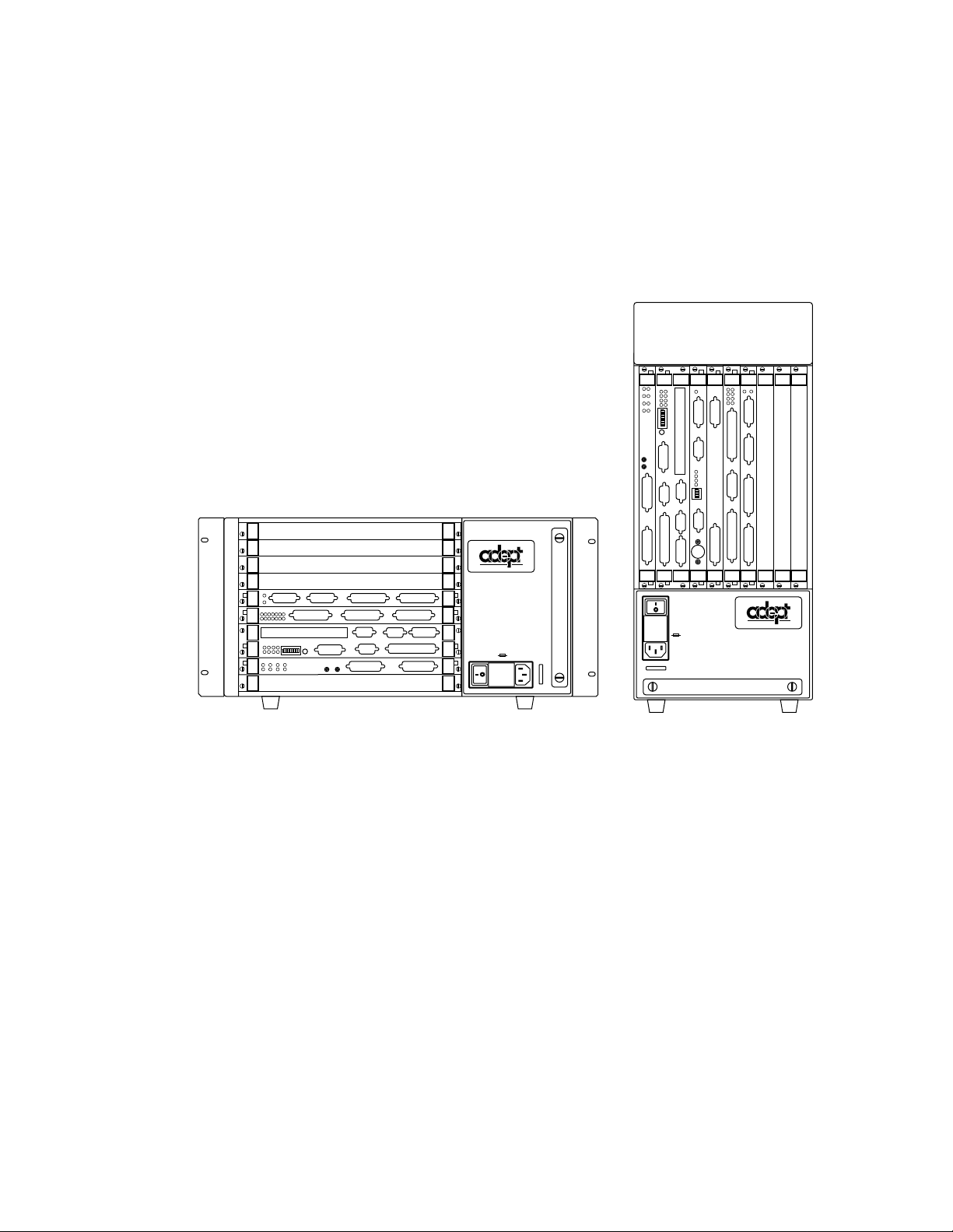
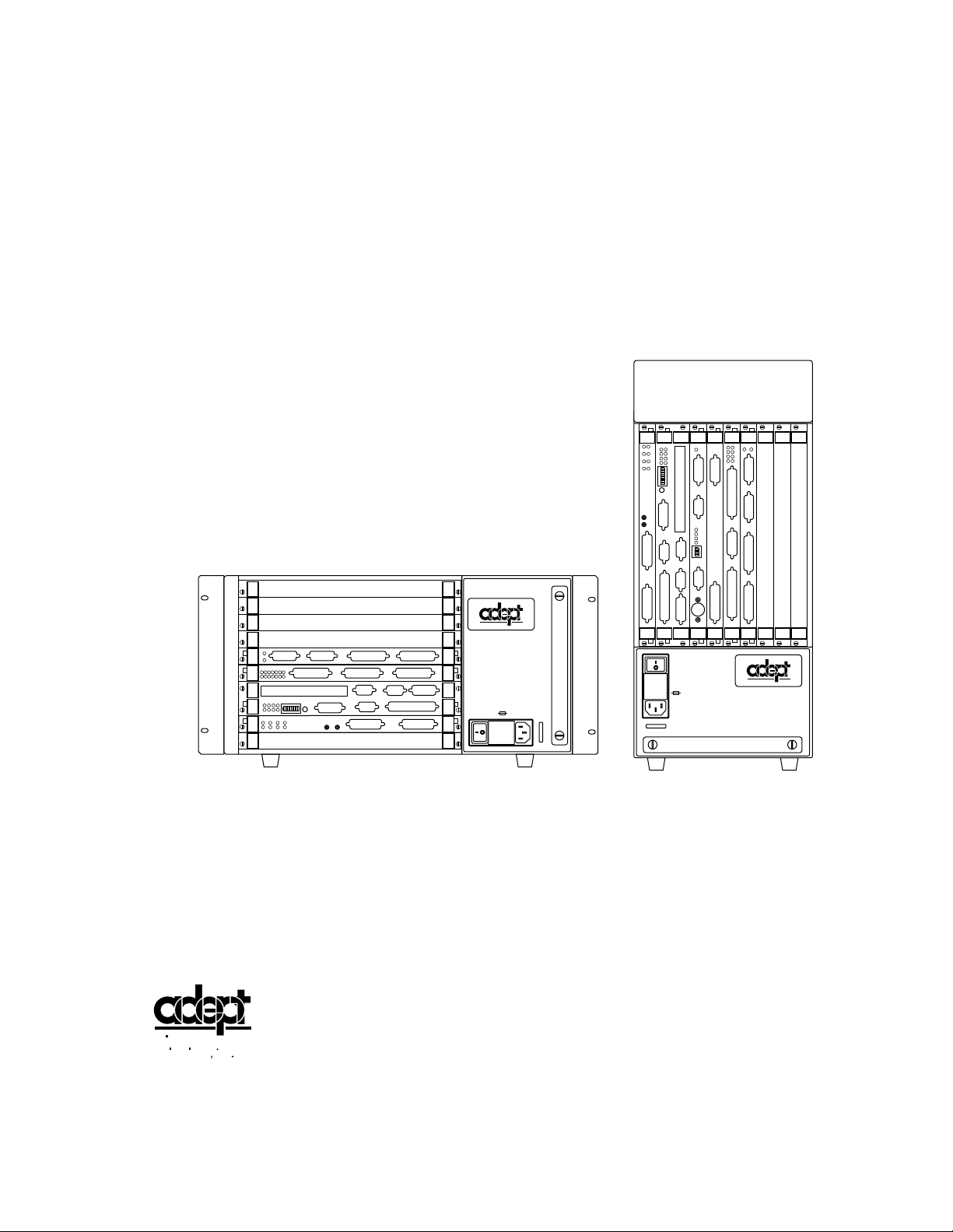
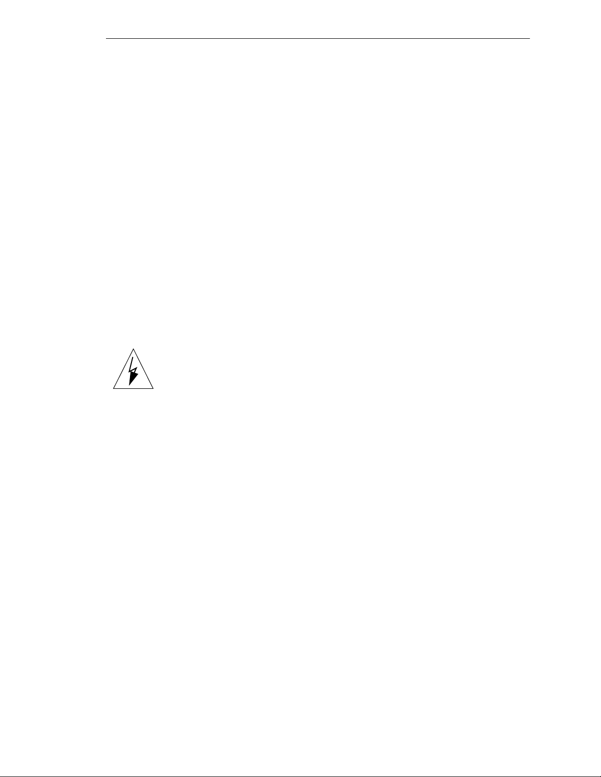
Figure 2-1. Adept MV-5 and MV-10 Controllers
Figure 2-2. Adept MV Controller Configuration
Figure 3-1. MV-5/MV-10 Power Entry Module
Figure 3-2. Insta lla tio n of User-S up pli ed Ex ter na l C onta c tor /P ower Su ppl y usin g V FP-1
Figure 3-3. Installa tio n of User-Supplied Externa l Contactor using VFP-3
Figure 3-4. MV-5/MV-10 Fuse Holder
. . . . . . . . . . . . . . . . . . . . . . .
Figure 3-5. A dept MV-5 Upper Backplane (P1) Jumper Plugs
Figure 3-6. Adept MV-10 Upper Backplane (P1) Jumper Plugs
Figure 3-7. Connecting the A-Series Monitor and Keyboard
Figure 3-8. R ack Mounting for MV-5/MV-10 Stand-Alone Controller
. . . . . . . . . . . . . . . . . .
. . . . . . . . . . . . . . . . . .
. . . . . . . . . . . . . . . . . . .
. . . . . .
. . . . . . . . . . .
. . . . . . . . . . .
. . . . . . . . . . . .
. . . . . . . .
203
13
17
25
26
27
29
32
32
34
37
Adept MV Controller User’s Guide, Rev C xv
Page 18

Table Of Contents
Figure 3-9. Panel Mounting for MV-5/MV-10 Stand-Alone C ontroller
. . . . . . . . .
Figure 3-10. Installing Mounting Brackets on MV-5 and MV-10 Robot Controllers
Figure 4-1. Power Entry Module
Figure 4-2. Adept MV Controller with Back Panel Open
Figure 4-3. Interna l Fuse Loc a tion s
Figure 4-4. Ad ept MV-8 Backplane Jumper Plugs
Figure 4-5. Adept MV-19 Backplane Jumper Plugs
Figure 4-6. Installing Mounting Brackets
Figure 5-1. RS-422/485 Female Connector Pin Locations (on 030 modu le)
Figure 5-2. RS-232/Term Male Connector Pin Locations (on 030 module)
Figure 5-3. Switch and Jumper Locations on the 030 Module
Figure 6-1. RS-422 Connector on 040 Module
Figure 6-2. RS-232 Connector on 040 Module
Figure 6-3. Switch and Jumper Locations on the 040 Module
Figure 7-1. RS-232 Serial I/O Connector Pin Locations on SIO Module
Figure 7-2. Typical Dig ital Inp ut Wiring on the SIO
Figure 7-3. Typical Dig ital Output Wiring on the SIO
Figure 7-4. Digital I/O Co nn ec tor Pin Locatio ns on S IO Mod ul e
Figure 7-5. E-Stop Diagram with VFP and MCP
Figure 7-6. Extern al Front Panel (VFP-1)
Figure 7-7. Extern al VME Fron t Pane l and M C P Installation
Figure 8-1. Moni tor Connector Pin Locati ons on VGB M odu le
. . . . . . . . . . . . . . . . . . . . . . . . . . .
. . . . . . . . . . . . . . .
. . . . . . . . . . . . . . . . . . . . . . . . .
. . . . . . . . . . . . . . . . . .
. . . . . . . . . . . . . . . . .
. . . . . . . . . . . . . . . . . . . . . . .
. . . . . .
. . . . . .
. . . . . . . . . . . .
. . . . . . . . . . . . . . . . . . . .
. . . . . . . . . . . . . . . . . . . .
. . . . . . . . . . . .
. . . . . . . .
. . . . . . . . . . . . . . . . . .
. . . . . . . . . . . . . . . . .
. . . . . . . . . . .
. . . . . . . . . . . . . . . . . . .
. . . . . . . . . . . . . . . . . . . . . . .
. . . . . . . . . . . . .
. . . . . . . . . . .
Figure 9-1. Sw itch Positions A and B in Relation to Arrows on SW1, SW3, and SW2
Figure 9-2. Switch Locations on VIS Module
Figure 9-3. Two-Camera Breakout Cable
Figure 9-4. Four-Camera Breakout Cable
Figure 9-5. Camera Cable Installation Drawing
Figure 9-6. Pin Locations for Camera Cable Connector (12-Pin Hirose Male)
Figure 11-1. VJI Belt Encoder Connector Pinout
Figure 11-2. VJI Belt Encoder Typical Input Circuity
Figure 13-1. Typ ical Digita l Input Setup
Figure 13-2. Typical Digital Output Setup
Figure 13-3. Switch and Jumper Locations on DIO PC Board
Figure A-1. Adept MV-5/10 Stand-Alone Outline Drawing
Figure A-2. A d ept MV- 5/10 Robot Outline Draw ing
Figure A-3. Adept MV-8 Outline Drawing
Figure A-4. Adept MV-19 Outline Drawing
Figure A-5. Mounting Bracket Hole Pattern Dimensions
Figure A-6. Adept External Front Panel (VFP-1) Dimensions
Figure A-7. MCP Cradle D imens io n s
. . . . . . . . . . . . . . . . . . . . . . . .
. . . . . . . . . . . . . . . . . . . .
. . . . . . . . . . . . . . . . . . . . .
. . . . . . . . . . . . . . . . . . . . .
. . . . . . . . . . . . . . . . . .
. . .
. . . . . . . . . . . . . . . . . .
. . . . . . . . . . . . . . . . .
. . . . . . . . . . . . . . . . . . . . . . .
. . . . . . . . . . . . . . . . . . . . . .
. . . . . . . . . . . .
. . . . . . . . . . . . .
. . . . . . . . . . . . . . . .
. . . . . . . . . . . . . . . . . . . . .
. . . . . . . . . . . . . . . . . . . .
. . . . . . . . . . . . . .
. . . . . . . . . . . .
. . .
.
38
40
47
49
51
53
53
56
61
62
68
73
74
78
84
88
89
91
94
96
98
106
111
112
113
114
115
118
134
135
146
147
154
162
163
164
165
166
167
168
xvi Adept MV Controller User’s Guide, Rev C
Page 19

Table Of Contents
Figure D-1. Holding the Operator’s MCP
Figure D-2. Cradling the Operator’s MCP
Figure D-3. MC P Lay out
Figure D-4. Data Entry Keys
. . . . . . . . . . . . . . . . . . . . . . . . . . . . . .
. . . . . . . . . . . . . . . . . . . . . . . . . . . .
. . . . . . . . . . . . . . . . . . . . . .
. . . . . . . . . . . . . . . . . . . . .
Figure D-5. MC P Pr edefi ne d Func ti on Buttons
Figure D-6. E DIT Func ti on Button
Figure D-7. D I SPLA Y Functi on B utton
Figure D-8. CLEAR ERROR Function Button
. . . . . . . . . . . . . . . . . . . . . . . . . .
. . . . . . . . . . . . . . . . . . . . . . . .
. . . . . . . . . . . . . . . . . . . . .
Figure D-9. C om mand (CMD) Fun c tion Bu tton
Figure D-10. Pro gra m Set Func tion Button
Figure D-11. Mode Control Buttons
Figu re D -12. Speed Ba rs
. . . . . . . . . . . . . . . . . . . . . . . . . . . . . .
Figure D-13. WOR LD State (SCARA)
Figure D-14. TOOL State
. . . . . . . . . . . . . . . . . . . . . . . . . . . . . .
. . . . . . . . . . . . . . . . . . . . . . . . .
. . . . . . . . . . . . . . . . . . . . . . . . .
Figure D-15. TOOL State (Six-Axis Robot)
Figure D-16. JOINT State (SCARA)
. . . . . . . . . . . . . . . . . . . . . . . . .
Figure D-17. JOINT State (Six-Axis Robot)
Figure D-18. FREE State (Four-Axis SCARA)
. . . . . . . . . . . . . . . . . . . . .
. . . . . . . . . . . . . . . . . . . . . .
. . . . . . . . . . . . . . . . . . . . . .
. . . . . . . . . . . . . . . . . . . . .
. . . . . . . . . . . . . . . . . . .
. . . . . . . . . . . . . . . . . .
180
181
182
183
184
185
186
188
188
190
191
193
194
196
197
198
199
200
Table 3-1. Operating Environment Requirements
Table 3-2. Adept MV Controller Power Requirements
Table 3-3. Power Cord Specifications
Table 3-4. MV-5 and MV-10
Fuse Ratings
. . . . . . . . . . . . . . . . . . . . . .
. . . . . . . . . . . . . . . . . . . . .
Table 3-5. Monitor Co mpatibility S pe c ifi c ati ons
Table 3-6. Tec h n ic al Spec if ic ations fo r MV C o ntroller
Table 4-1. Operating Environment Requirements
Table 4-2. Adept MV Controller Power Requirements
Table 4-3. Power Cord Specifications
. . . . . . . . . . . . . . . . . . . . . .
Table 4-4. Voltage Selection Jumper Settings
Table 4-5. Fuse Rati ngs
. . . . . . . . . . . . . . . . . . . . . . . . . . . . . .
. . . . . . . . . . . . . . . . .
. . . . . . . . . . . . . . .
. . . . . . . . . . . . . . . . . .
. . . . . . . . . . . . . . .
. . . . . . . . . . . . . . . . .
. . . . . . . . . . . . . . .
. . . . . . . . . . . . . . . . . .
Table 4-6 . Tec hnica l Specific ations fo r M V - 8/19 Controlle r s
Table 5-1. RS-422/485 Connector Pin Assignments
Table 5-2. RS-232/Term Connector Pin Assignments
. . . . . . . . . . . . . . . .
. . . . . . . . . . . . . . . .
Table 5-3. Pin Assignments for 9-Pin to 25-Pin (DCE) Cable
List of Tables
. . . . . . . . . . . .
. . . . . . . . . . . .
23
24
28
29
35
41
45
46
47
48
50
57
61
62
63
Adept MV Controller User’s Guide, Rev C xvii
Page 20

Table Of Contents
Table 5-4. Pin Assignments for 9-Pin to 25-Pin (DTE) Cable
Table 5-5. Pin Assignments for 9-pin to 25-pin (Wyse WY-60 Terminal) Cable
Table 5-6. Pin Assignments for 9-pin to 9-pin (AT-Compatible) Cable
Table 5-7. Typical 25-pin Null-Modem Adaptor Pinout
Table 5-8. Address Settings for the 030 Processor Module
Table 5-9. Jumper Settings for 030 Processor Module
Table 5-10. 030 Technical Specifications
. . . . . . . . . . . . . . . . . . . . . .
Table 6-1. RS-422 Connector Pin Assignments (on 040 Module)
Table 6-2. RS-232/Term Connector Pin Assignments (on 040 Module)
Table 6-3. Pin Assignments for 25-pin to 25-pin (Wyse WY-60 Terminal) Cable
Table 6-4. Address Settings for the 040 Processor Module
Table 6-5. Jumper Settings for 040 Processor Module
Table 6-6. 040 Technical Specifications
Table 7-1. SIO Front Panel DIP Switch Functions
. . . . . . . . . . . . . . . . . . . . . .
. . . . . . . . . . . . . . . . . .
Table 7-2. RS-232 Serial I/O Connector Pin Assignment on SIO Module
Table 7-3. DI O Input Spe c ific ations (S IO m o d u le )
Table 7-4. DIO Output Specifications (SIO module)
. . . . . . . . . . . . . . . . . .
. . . . . . . . . . . . . . . . .
Table 7-5. Di g ital I/O C onnector Pin Assignm e nt s on SIO Module
Table 7-6. Terminal Assignment of the Terminal Block on the Back of the VFP
Table 7-7. MCP Cable Connector Pinout
. . . . . . . . . . . . . . . . . . . . .
Table 7-8. MCP Connector: Manufacturer’s Information
Table 7-9. SIO Fron t Panel Ca bl e/C onn e ctor Pin Assig nme n ts
Table 7-10. Technical Specifications
. . . . . . . . . . . . . . . . . . . . . . .
Table 8-1. VGB Module Front Panel DIP Switch Functions
Table 8-2. Mo ni tor Con ne ctor Pin Assi gnme n ts
Table 8-3. Keyboard Connector Pin Assignments
Table 8-4. Pointer Connector Pin Assignments
Table 8-5. Technical Specifications
. . . . . . . . . . . . . . . . . . . . . . .
Table 9-1. Switch Settings for VIS Module 1
Table 9-2. Switch Settings for VIS Module 2
. . . . . . . . . . . . . . . . . .
. . . . . . . . . . . . . . . . .
. . . . . . . . . . . . . . . . . .
. . . . . . . . . . . . . . . . . . . .
. . . . . . . . . . . . . . . . . . . .
Table 9-3. Breakout Cable Camera Connector Pin Assignments
Table 9-4. Breakout Cable Strobe and Power Connector Pin Assignments
Table 9-5. Ad ept 10- Mete r Cam era Cable P in Assignments
Table 9-6. Tw o-C am er a Brea ko ut Cabl e Pin Assig nments
. . . . . . . . . . . . .
. . . .
. . . . . . . .
. . . . . . . . . . . . . . .
. . . . . . . . . . . . . .
. . . . . . . . . . . . . . . .
. . . . . . . . . . .
. . . . . . .
. . .
. . . . . . . . . . . . .
. . . . . . . . . . . . . . . .
. . . . . . .
. . . . . . . . . .
. . . .
. . . . . . . . . . . . .
. . . . . . . . . .
. . . . . . . . . . . . .
. . . . . . . . .
. . . .
. . . . . . . . . . .
. . . . . . . . . . . .
Table 9-7. Four-Camera Breakout Cable Pin Assignments (sorted by destination)
Table 9-8. Four-Camera Breakout Cable Pin Assignments (sorted by origin)
Table 9-9. Technical Specifications
Table 10-1. VMEbus Address Switch Settings for MI3/MI6 Module
Table 10-2. Technical Specifications
Table 11-1. VMEbu s Ad dr ess S witc h Sett ings for VJ I Mod ule
. . . . . . . . . . . . . . . . . . . . . . .
. . . . . . . . .
. . . . . . . . . . . . . . . . . . . . . . .
. . . . . . . . . . . .
. . .
.
64
64
65
66
67
68
69
73
75
76
77
77
79
83
84
86
87
90
95
99
100
101
102
105
106
107
107
108
111
111
116
117
118
119
120
122
124
127
129
133
xviii Adept MV Controller User’s Guide, Rev C
Page 21

Table Of Contents
Table 11-2. VMEBus Ad dre ss S ettin gs for Mul tip le Servo B oard S ystem s
Table 11-3. Belt Encod e r Conn e ctor Pin Assi gnme n ts
Table 11-4. Technical Specifications
Table 12-1. Address Settings for VFI Module
Table 12-2. Technical Specifications
Table 13-1. DIO Input Circuit Specifications
. . . . . . . . . . . . . . . . . . . . . . . .
. . . . . . . . . . . . . . . . . . . .
. . . . . . . . . . . . . . . . . . . . . . . .
. . . . . . . . . . . . . . . . . . . .
Table 13-2. DIO Output Voltage Range Settings
Table 13-3. Digital Output Circuit Specifications
Table 13-4. DIO P1 Input C ab le Pin Assi gnme n ts
Table 13-5. DIO P2 Input C ab le Pin Assi gnme n ts
Table 13-6. DIO P3 Outp ut Ca bl e Pin Assignm en ts
Table 13-7. DIO P4 Outp ut Ca bl e Pin Assignm en ts
Table 13-8. Switch Settings f or S1 on DIO Module
Table 13-9. DIO Technical Specifications
Table 14-1. Spare Parts From Adept
Table 14-2. Spare Parts From Third Parties
Table 14-3. Spare Parts From Adept
Table 14-4. Spare Parts From Third Parties
. . . . . . . . . . . . . . . . . . . . .
. . . . . . . . . . . . . . . . . . . . . . . .
. . . . . . . . . . . . . . . . . . . . .
. . . . . . . . . . . . . . . . . . . . . . . .
. . . . . . . . . . . . . . . . . . . . .
Table C-1. Sources for International Standards and Directives
Table C-2. E M C Test Results
Table C-3. Operator Indicator Color-Code
Table C-4. Service Indicator Color-Code
. . . . . . . . . . . . . . . . . . . . . . . . . . . .
. . . . . . . . . . . . . . . . . . . .
. . . . . . . . . . . . . . . . . . . . .
. . . . . . . . . . . . . . .
. . . . . . . . . . . . . . . . . .
. . . . . . . . . . . . . . . . . .
. . . . . . . . . . . . . . . . . .
. . . . . . . . . . . . . . . . . .
. . . . . . . . . . . . . . . . .
. . . . . . . . . . . . . . . . .
. . . . . . . . . . . . . . . . .
. . . . . . . . . . .
. . . . . . .
134
134
136
139
140
143
144
145
149
150
151
152
153
155
159
159
160
160
174
176
177
178
Adept MV Controller User’s Guide, Rev C xix
Page 22

Page 23

Introduction 1
1.1 How to Use This Ma n u al
. . . . . . . . . . . . . . . . . . . . . . . . . .
Follow These Steps to Install and Configure the Adept MV Controller
Related Manuals
. . . . . . . . . . . . . . . . . . . . . . . . . . .
Standard Manuals
Other Adept Pro duct M a nuals
Optional V
+
Develop e r’s M an ual s
1.2 Warnings, Cautio ns, and Notes
1.3 Safety
. . . . . . . . . . . . . . . . . . . . . . . . . . . . . . . . . .
Reading and Tr aini ng for Us e rs and Ope rator s
Syste m Safe guards
. . . . . . . . . . . . . . . . . . . . . . . . . .
Safety Features on External VME Front Panel (VFP)
Computer-C on tro lled Robo ts and Motion Device s
Manually-Co ntr oll ed Robots and Motion D evic es
Other Computer-Controlled Devices
Progr a m S e curity
Overspeed Protection
Voltage Interrup tion s
. . . . . . . . . . . . . . . . . . . . . . . . . . .
. . . . . . . . . . . . . . . . . . . . . . . . .
. . . . . . . . . . . . . . . . . . . . . . . . .
Inappropriate Uses of the Adept MV Controller
1.4 Standards Compliance
1.5 How Can I Get Help?
. . . . . . . . . . . . . . . . . . . . . . . . . .
. . . . . . . . . . . . . . . . . . . . . . . . . . .
. .
. . . . . . . . . . . . . . . . . . . . . . .
. . . . . . . . . . . . . . . . .
. . . . . . . . . . . . . . .
. . . . . . . . . . . . . . . . . . . . . .
. . . . . . . . . . . . .
. . . . . . .
. . . . . . .
. . . . . . . .
. . . . . . . . . . . . . .
. . . . . . . . . . . .
2
2
2
2
3
3
4
4
4
5
5
5
5
5
6
6
6
6
7
8
Within the Continental United States
Servic e Calls
Application Questions
Training Information
Within Europe
. . . . . . . . . . . . . . . . . . . . . . . . . .
. . . . . . . . . . . . . . . . . . . . .
. . . . . . . . . . . . . . . . . . . . . .
. . . . . . . . . . . . . . . . . . . . . . . . . . . . .
. . . . . . . . . . . . . . . . . .
Outside Continental United States or Europe
Adept World Wide Web Site
Adept Bulletin Board Service
. . . . . . . . . . . . . . . . . . . . . .
. . . . . . . . . . . . . . . . . . . . . .
Adept MV Controller User’s Guide, Rev C 1
. . . . . . . . . . . . . .
8
8
8
8
9
9
9
9
Page 24

Chapter 1 - Introduction
1.1 How to Use This Man ual
Follow These Steps to Install and Configure the Adept MV Controller
1. Read Chapter 1 to learn about Safety and Customer Service issues and
Chapter 2 to get a n ov e rview of the Ade p t MV co n t rol l e r and its com p onents.
2. Read Chapter 3 or 4 to learn the steps in installing the controller. It covers AC
power installation, fuse information, installing and removing modules,
connecting monitors and keyboards, and installing in a rack or panel mount.
3. Read Chapters 5, 6, and 7 which cover the requir ed Syst em Proc essor (030 or 040)
and System I/O modules. Pay particular atten ti on to th e Em ergency Stop
circuitry in Chapter 7.
4. Read the appropriate chapters (8 – 13), depending on which optional modules
you have in your controller. They explain the function of the indicator s and
connec tors on th e front of eac h mo d u l e . The y co ver the I np u t / Output (I/O)
capabilities of certain modules and the VMEbus address of all modules. These
chapters al so explai n any s peci al sw itch or jump er set tings that you migh t hav e to
set on parti cular modul e s.
5. Read Chapter 14 and Appendix A, B, and C for maintenance, dimension,
external trigger, and standards compliance informatio n.
6. Read Appe ndix D to learn how to use the Manual Control Pendant and
Appendix E for a list of the most common V
+
System Error messages.
Related Manuals
Adept products come with a set of documentation that is defined by the products you
have ordered. In add ition, there are optional manuals ava il able if you ar e going to be
programming the Adept system. This man u al refers to both the standar d and optional
manuals. The following sections give a brief description of the contents and organization
of the Ad e p t do cument a tion se t.
Standard Manuals
In addition to th is Adept Controller User's Guide, the following manuals are shipped with
the sy st e m :
Manual Material Covered
+
Operating System User’s Guide A description of the V+ operating system.
V
Loading, storing, and executing programs is
covered in th is ma n ual.
Instructions for Ade pt Uti lity Progra ms Adept provides a series of programs for
configuring and calibrating various features
of your Adept system. These utility programs
are described in th is manual.
+
Release Notes Descriptions of the chan ges to V+. This
V
document is updated as each version of V
released.
+
is
2 Adept MV Controller User’s Guide, Rev C
Page 25

How to Use This Manual
Manual Material Covered
+
Language User’s Guide V+ is a complete high-level language as well
V
as an operating system . This manu al covers
+
programming principles for creating V
programs.
Other Adept Product Manuals
When you order AdeptVision VME, AdeptMotion VME, AdeptForce VME, or any AIM
software product, you will receive manuals that cover those products. Also, optional
hardware such as the Manual Control Pendant will come with a manual. A partial list is
shown b e l o w.
Manual Material Covered
AdeptVision VME User's Guide Concepts and strategies for programming the
AdeptVision VME syst e m. (see also the
optional AdeptVision Reference Guide below)
AdeptMotion VME Developer’s Guide Install ation, configu ration, and tuning of an
AdeptMotion VME system.
AdeptForce VME User’s Guide Install a tion, operation, and programming of
the AdeptForce VME product.
+
Optional V
If you will be programming V
Developer’s Manuals
+
applica tions, you should ord e r the optional V+ devel-
oper’s manuals (first two in the list below). These manuals contain a complete description
+
of the commands, instructions, functions, and other features available in the V
language
and operating system. These manuals are essential for advanc ed appli cations programming.
If you will be programming vision applications, you should order the AdeptV i sion Refer ence
Guide (in addi tion to the V
+
developer’s manuals).
Manual Material Covered
+
Operating System Reference Guide Descriptions of the V+ operating system
V
commands (known as mon itor comman ds).
+
Language Reference Guide A complete des cr ipt ion of the k eywords in the
V
basic V
AdeptVision Reference Guide Descriptions of the additional V
+
language system.
+
keywords
available with the AdeptVision VME option.
Adept MV Controller User’s Guide, Rev C 3
Page 26

Chapter 1 - Introduction
1.2 Warnings, Cautions, and Notes
There are three levels of special notation used in this manual. They are:
WARNING:
indicated in a “WARNIN G” are not complied with. A warning statement
typically describes the hazard, its possible effect, and the measures that
must be ta k en to red uce the h a za rd.
CAUTION:
in the “
Injury or major equipment damage could result if the actions
Damage to you r equi pment c oul d r esul t if the ac tion spec ifi ed
CAUTION
” is not complied with .
!
NOTE:
point or procedure, or gives a tip for easier operation.
A “
1.3 Safety
Reading and Training for Users and Operators
Adept systems can include computer-controlled mechanisms that are capable of moving
at high speeds and exerting considerable force. Like all robot and motion systems, and
most indust ria l eq uipme nt, th ey must b e tr ea ted with resp ect by the use r and the op era tor.
” provides supplementary information, emphasizes a
NOTE
This manua l sh ou ld be rea d by all personnel who operate or maintain Adept systems, or
who work wi thin or near the workcel l.
We r e co mmend yo u r ead the American National Standard for Industrial Robot Systems - Safety
Requirements, published by the Robotic Industries Association(RIA), in conjunction with
the American National Standards Institute. The publication, ANSI/RIA R15.06 - 1992,
contains guidelines for robot system installation, safeguarding, maintenance, testing,
start-up, and operator training.
We also recommend you read the European Standard EN 60204, Safety of Machinery –
Electrical Equipment of Machines, particularly if the country of use requires a CE-certified
installati on . (See section C.1 on page 174 for or dering information for nat io na l and
international standards.)
This manual assumes that the user has attended an Adept trainin g cou rse and has a basic
working knowledge of the system. The user should provide the necessary additional
training for all personnel who will be work ing with the syste m .
There are several warnings in this manual that say only skilled or instructed persons
should attempt certain proced ures. These are defined as:
4 Adept MV Controller User’s Guide, Rev C
Page 27
• Skilled persons have technical knowledge or sufficient experience to enable them
to avoid the dangers which electricity may create (engineers and technicians).
• Instructed persons are adequately advised or supervised by skilled persons to
enable them to avoid the dangers which electricity may create (operating and
maintenance staff).
System Safeguards
Safeguards should be an in te g ral part of robot or motion wor kcell design, installation,
operator training, and operating procedures.
Adept systems have vari ou s communication features to aid in constructi ng system
safeguards. These include the emergency stop cir cuitry and digital input and output lines.
These features are described in Chapter 7 of this user’s guide.
Safety Features on External VME Front Panel (VFP)
The optional external VME Front Panel (VFP) has three important safety features, the
HIGH POWER
and
PROGRAM RUNNING
you choose no t to u se the VFP, you should provi de similar safety features by using the
Front Panel/MCP and Digital I/O connectors on the System I/ O modul e . Refer to
Chapter 7 for more information, or call Adept Customer Service at the numbers listed in
section 1.5 on page 8.
indicator s, and the
EMERGENCY STOP
switch. If
Safety
WARNING:
PROGRAM RUNNING
Entering the workcell when either the
HIGH POWER
light is on can result in severe injury. Th is war ning
or the
applies to each of the next three sections.
Computer-Controlled Robots and Motion Devic es
Adept systems are computer controlled, and the program that is currently running the
robot or motion device may cause it to move at times or along paths you may not
anticipate. When the
HIGH POWER
light or the
PROGRAM RUNNING
light on the opti onal
VFP are illuminated, do not enter the workcell because the robot or motion device might
move unexpectedly. (The
LAMP TEST
button on the VFP allows these lights to be
periodically checke d. )
Manual l y -Contr ol l ed Robots and Motion Devices
Adept robots and other motion devices can also be controlled manually when the
POWER
light on the VFP is illuminated. When this light is lit, motion can be initiated from
HIGH
the system ke yboard or from the optional Manual Contr ol Pendant (MCP). If you have to
enter the workcell when this light is lit, press the
MAN/HALT
button on th e MCP. This wi ll
prevent anyone else from initiat ing unexpected motion fr om the system keyboard .
Other Computer-Controlled Devices
In addition, Adept systems can be programmed to control equi p me nt or devices other
than the robot or main motion device. The program controllin g these other devices may
cause them to operate unexpectedly. Make sure that safeguards are in place to prevent
personnel from entering the workcell when a program is running.
Adept Technology highly recommends the use of add itional safety features such as light
curtai ns, safety ga te s, or safety f loor mats to prevent entry to the workcell while
POWER
is enabled. These devices can be connected using the emergency stop circuitry.
HIGH
Adept MV Controller User’s Guide, Rev C 5
Page 28

Chapter 1 - Introduction
Program Security
Programs and data stored in memory can be changed by trained p e rsonnel using the V+
commands and i nstructions documented in the V
alteration of programs, you should restrict access to the keyboard. This can be done by
placing the keyboard in a locked cabinet. Alternativ ely, the V
instruc t ions can be us e d in you r pro g ra m s to res tr i ct ac ce s s to the V
+
manuals. To prevent unauthorized
+
ATTACH and FSET
+
command prompt.
Overspeed Protection
Overspeed protection for a robot or motion system has to be taken into account during
system integration by the integrator or end-user. Overspeed protection is not guaranteed
by the controller hardwar e al one. The V
protection capabiliti es.
+
system software offers some overspeed
Voltage Interruptions
If the AC supply to the controller is interrupted, the passive E-stop output will be
automatically turned on (opened). In addition, the High Power, Brake Release, and Drive
Enable signals will be turned off. You must ensure that these signals are used to prevent a
hazardous condition.
Inappropriate Uses of the Adept MV Controller
The Adept MV controller is intended for use as a component sub-assembly of a complete
industrial automation system. The Adept MV controller sub-assembly must be installed
inside a s u itabl e en clo sur e. In st alla tion and usa ge must comp ly with al l s af ety ins tr uct ion s
and warnings in this manual. Installation and usage must also comply with all applicable
local or national statutory requirements and safety standa rds. The Adept MV controll e r
sub-assembly is not intended for use in any of the following situations:
• In hazardous (explosive) atmospheres
• In mobile, portable, marine, or aircraft systems
• In life-support systems
• In residential installations
• In si tuations where the Adept MV controller sub-assembly may come into contact
with liquids.
• In si tuations where the Adept MV controller sub-assembly will be subject to
extremes of heat or humidity. See specifications for allowable temperature and
humidity ranges.
6 Adept MV Controller User’s Guide, Rev C
Page 29

1.4 Standards Compliance
The Adept MV controller is intended for use with other equipment and is considered a
sub-assembly rather than a complete piece of e quipment on its own. The Adept MV
control l e r meet s th e requirements of EN 60204, IEC 1131-2, IEC 73, and IEC 447 safety
standards. See the Decl aration of Conf ormity (just after the Title Page) for additional
compliance information about this product.
To maintain compliance with the above sta nd ards, the controlle r must be insta lled a nd
used prope rly with any addi tional equipment, in accor dance with all regulation s of the
standards. You must also carefully follow all installation instructions in this user guide.
See Appendix C for additional inform ati on on standards compliance.
Standards Compliance
Adept MV Controller User’s Guide, Rev C 7
Page 30

Chapter 1 - Introduction
1.5 How Can I Get Help?
Within the Continental United States
Adept Technology maintains a Cust ome r Serv ice Cent er a t its headquart ers in San Jos e,
CA. The phone numbers are:
Serv ice Calls
(800) 232-3378
5:00am - 5:00pm PST (24 hour emergency coverage, 7 days a week)
(408) 433-9462 FAX
NOTE:
serial number of the controller (see page 44 for information on the ID
label). If your system includes an Adept robot, also have the serial
numb e r of the robot. Th e se rial num b e rs can be determi ne d by usi n g th e
ID command (see the V
Application Questions
Contact your regional Application s sup port center as show n belo w.
San Jose, CA 408-434-5033
Cincinnati, OH 513-792-0266
Southbury, CT 203-264-0564
When calling with a controller re la ted quest ion, pl ease have the
+
Operating System Use r’s Guide).
Western Region States:
Fax 408-434-6248
8:00am - 5:00pm PST
Fax 513-792-0274
8:00am - 5:00pm EST
Fax 203-264-5114
8:00am - 5:00pm EST
LA, AR, MO, TX, OK, KS, NE,
CO, WY, MT, NM, AZ, UT, NV,
ID, WA, OR, CA
Midwestern Region States:
MI, OH, West PA, West NY, IN,
KY, TN, AL, MS, IL, WI, IA, MN,
ND, SD
Eastern Region States:
ME, NH, VT, MA, CT, RI, East
NY, East PA, NJ, DE, MD, VA,
WV, NC, SC, GA, FL
Training Information
For information regarding Adept Training Courses in the USA, please call (408) 474-3246.
You can see the Adept Training class schedule on the Adept Web site – see page 9.
8 Adept MV Controller User’s Guide, Rev C
Page 31

How Can I Get Help?
Within Europe
For service calls, application ques tions, and tr aining info rm ati on in Europe, Adept
Technology maintains a Customer Service Center in Dortmund, Germany. The phone
numbers are:
(49) 231/75 89 40 from within Europe (Monday to Friday, 8:00 am to 5:00 PM)
(49) 231/75 89 450 FAX
Outside Continental United States or Europe
For service calls, application questions, and training information, call the Adept Customer
Service Center in San Jose, California USA:
1 (408) 434-5000
1 (408) 433-9462 FAX (service requests)
1 (408) 434-6248 FAX (application questions)
Adept World Wide Web Site
Adept has a Web site at the following URL:
http: //www.adept.com
You can find current information about Adept products and services. You can go to the
Technical Publications section in the Services area and find information about Adept’s
manuals , including a section on corrections and upd a te s.
Adept Bulletin Board Service
Adept maintains a bulletin board service for Adept customers. Adept posts application
hints and utilities to this bulletin board and users may post their own hints and
application notes. There is no charge for access to the bulletin board. (You will, of course,
incur normal long-distance phone char ges for the call to the BBS.) The BBS number i s (203)
264-5590. The first time you call you will be able to set up an account right from the BBS. If
you have any questions, call (203) 264-0564 and ask about the BBS.
Adept MV Controller User’s Guide, Rev C 9
Page 32

Page 33

Over view 2
2.1 Introduction
2.2 Controller Models
Adept MV-5 Controller
Adept MV-10 Controller
Adept MV-8 Controller
Adept MV-19 Controller
. . . . . . . . . . . . . . . . . . . . . . . . . . . . . .
. . . . . . . . . . . . . . . . . . . . . . . . . . . .
. . . . . . . . . . . . . . . . . . . . . . . .
. . . . . . . . . . . . . . . . . . . . . . .
. . . . . . . . . . . . . . . . . . . . . . . .
. . . . . . . . . . . . . . . . . . . . . . .
2.3 A-Series and S-Series Controller Options
Adept A-Series Option
Adept S-Series Option
2.4 Standard Modules
System Processor (030 or 040)
030 Module
040 Module
. . . . . . . . . . . . . . . . . . . . . . . . . . .
. . . . . . . . . . . . . . . . . . . . . . . .
. . . . . . . . . . . . . . . . . . . . . . . .
. . . . . . . . . . . . . . . . . . . .
. . . . . . . . . . . . . . . . . . . . . . . . . .
. . . . . . . . . . . . . . . . . . . . . . . . . .
System Input/ Output Module (SIO)
2.5 Optional Modules
Adept Grap hi c s M odule (VGB)
. . . . . . . . . . . . . . . . . . . . . . . . . . . .
. . . . . . . . . . . . . . . . . . .
AdeptVision VM E Inter fac e M od ul e (VIS)
AdeptMoti on In terfa c e Mod ule s (MI3/MI6)
Adept VME Joint Interfac e Mod ul e (VJI)
AdeptForce VME Module (VFI)
. . . . . . . . . . . . . . . . . . .
Digital Input/ Output Module (DI O )
Auxiliary Processor
2.6 Optional Equipment
. . . . . . . . . . . . . . . . . . . . . . . . . .
. . . . . . . . . . . . . . . . . . . . . . . . . .
. . . . . . . . . . . . . . . .
. . . . . . . . . . . . . . . . . .
. . . . . . . . . . . . . . .
. . . . . . . . . . . . .
. . . . . . . . . . . . . . .
. . . . . . . . . . . . . . . . . .
12
12
12
12
14
14
14
14
15
15
15
15
15
15
16
16
16
16
18
18
18
18
19
External Front Panel (V FP-1 or VFP-3)
Manual Control Pendant (MCP)
AdeptNet
. . . . . . . . . . . . . . . . . . . . . . . . . . . . . .
A-Series Color Monitor
A-Series Extended Keyboard
Third-Party Terminals for an S-Series Controller
2.7 Product Descriptions
AdeptVision VME
AdeptMotion VME
AdeptForce VME
Adept MV Controller User’s Guide, Rev C 11
. . . . . . . . . . . . . . . . .
. . . . . . . . . . . . . . . . . . .
. . . . . . . . . . . . . . . . . . . . . . . .
. . . . . . . . . . . . . . . . . . . . .
. . . . . . . . . . . .
. . . . . . . . . . . . . . . . . . . . . . . . . .
. . . . . . . . . . . . . . . . . . . . . . . . . .
. . . . . . . . . . . . . . . . . . . . . . . . . .
. . . . . . . . . . . . . . . . . . . . . . . . . .
19
19
19
19
19
20
20
20
20
20
Page 34

Chapter 2 - Overview
2.1 Introduction
The Adept MV series controllers are based on the VMEbus specification, and the slide-in
modules are designed to the 6U VME size. There are four models of controllers, the Adept
MV-5, MV-8, MV-10, and the Adept MV-19.
2.2 Controller Models
Adept MV-5 Controller
The Adept MV-5 controlle r is a 5-slot chassis that is available i n eit her a stand-alone or
robot confi g uration; see Figure 2-1. The stand-alone version stands hori zon tal ly and can
be mounted in a standar d 19-inc h equipment rack. The robo t version st ands vert ically an d
can be joined to an Adept PA-4 power chassis, and the joined units can be mounted in a
standard 19-inch equipment rack.
The Adept MV-5 requires two modules: the System Process or module (030 or 040) and the
System Input/Output (SIO) module. The System Processor module occupies backplane
slot 1 and the Sys te m I nput/Output module occupies slots 2 and 3. The re maining two
slots can be populated wi th various com b in ations of opti onal Adept modules; see
Figure 2-2.
The Adept MV-5 cha ssis has an aut o-ranging 100 -120/200 -240 VAC single-phase, 250 -watt
power supply. The chassi s is cooled by a fan loc a ted in the lower front sec tion. Incoming
air is cleaned by a reusable filter.
Adept MV-10 Controller
The Adept MV-10 control ler is a 10-slot chassis that is available in either a stand-alone or
robot confi g uration; see Figure 2-1. The stand-alone version stands hori zontally and can
be mounted in a standar d 19-inc h equipment rack. The robo t version st ands vertically and
can be joined to an Adept PA-4 power chassis, and the joined units can be mounted in a
standard 19-inch equipment rack.
The Adept MV-10 requi res two modules: the Syst em Processor module (030 or 040) and
the System Input/Output (SIO) module. The System Processor module occupies
backplane slot 1 and the System Input/Output module typically occupies slots 2 and 3.
The remaining sev e n slots can be populat e d with variou s combinations of option al Adept
modules; see Figure 2-2.
The Adept MV-10 chassis has an auto-ra ngin g 100-120/200-240 VAC single-phase,
350-watt power supply. The chassis is cooled by a fan located in the lower front section.
Incoming air is cleaned by a reusable filter.
12 Adept MV Controller User’s Guide, Rev C
Page 35
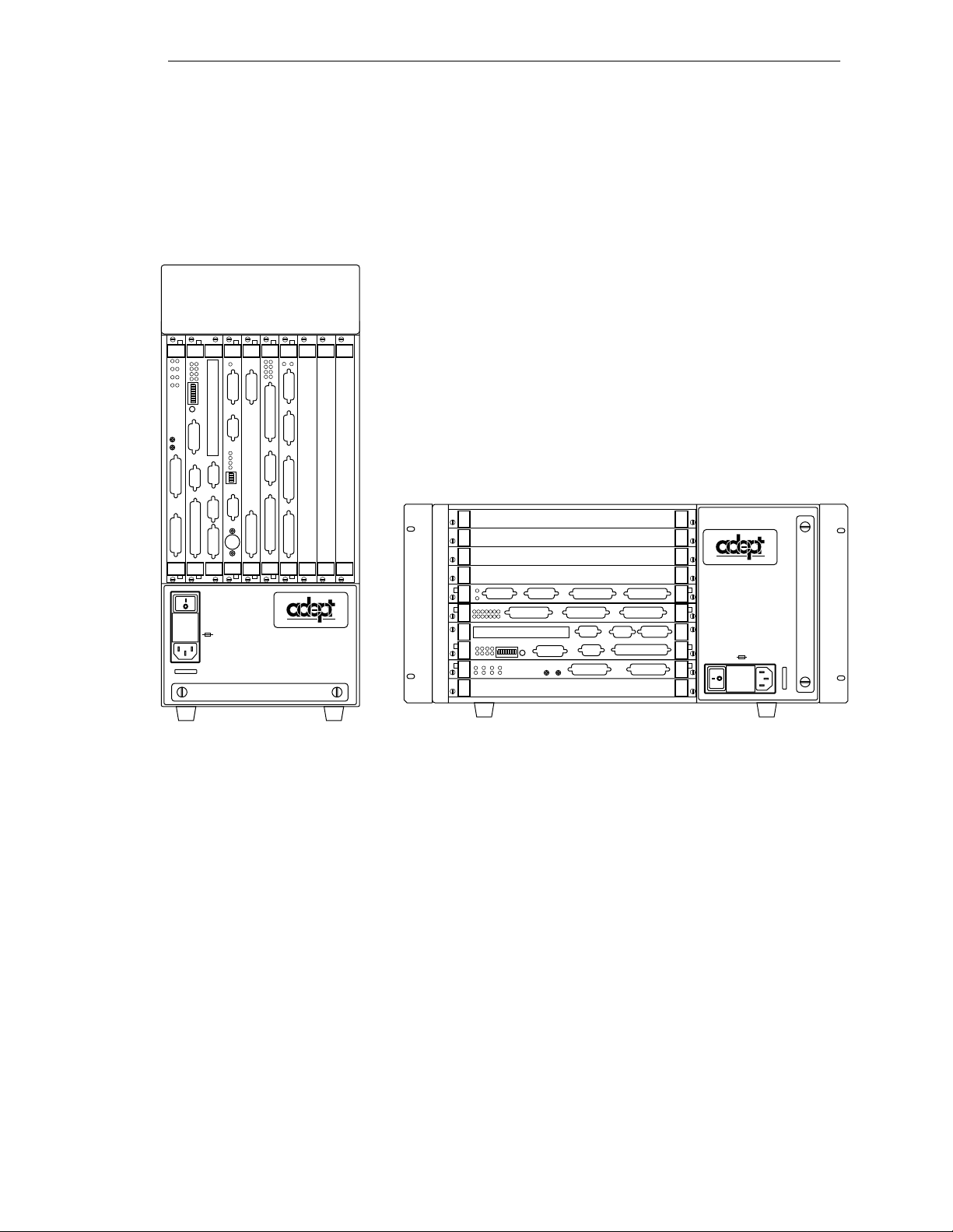
Controller Models
(
)
(
040
SIO
STP
SF
1
OK
2
SCR
A
ESTOP
3
ACC V
C
B
4
SCSI
ON
VME
D
2
3
41
OK
6
7
D
85
R
I
RESET
V
E
A
F
P
/
ABORT
M
C
P
RESET
R
R
S
R
S
2
S
4
3
2
2
2
3
2
2
#1
R
S
2
I
3
/
2
O
R
2
S
4
2
V
3
E
2
T
1
/
H
0
T
E
0
E
R
m
R
N
A
M
E
T
#2
USE ONLY WITH
WARNING:
250V FUSES
FOR CONTINUED PROTECTION
AGAINST RISK OF FIRE,
REPLACE ONLY WITH SAME
TYPE AND RATING OF FUSE.
5AT
~100-240V
50/60HZ
VJI
VGB
VIS
DIO
FAIL PASS
HPE
ES
OK
2
1
4
3
V
V
6
5
I
D
E
O
B
U
S
M
O
N
I
T
O
R
1
2
3
4
ON
2
3
41
P
O
I
N
T
E
R
KEYBOARD
I
I
N
D
P
E
U
O
T
S
B
U
S
I
N
P
U
T
S
AMPLIFIER
SIGNAL
O
U
T
P
U
T
S
BELT
ENCODER
C
A
M
O
E
U
R
T
A
P
S
U
/
T
S
S
T
R
O
B
E
ARM
S
SIGNAL
Adept MV Robot Controller
example shown: MV-10
®
DIO
®
FAIL PASS
I
I
T
T
S
NPU
HPE
DE1
DE2
DE3
DE4
DE5
DE6
MI6
ESF1F2F3F4
F5
F6
OK
ESTOP
ACC V
SCSI
SIO
123
4
STP
SCRCVME
040
ABD
SF
S
NPU
E
N
CODER
I
V
E
D
R
A
OK
RESET
6785ON2341
F
P
ABORT
T
T
S
P
U
U
O
A
E
C
HIN
M
232
S
R
232
S
R
/
P
C
M
RESET
422
S
R
T
T
S
P
U
U
O
S
ERV
O
232
S
R
T
T
E
E
HER
N
WARNING:
FOR CONTINUED PROTECTION AGAINST RISK OF FIRE,
A
#2
R
M
REPLACE ONLY WITH SAME TYPE AND RATING OF FUSE.
USE ONLY WITH
250V FUSES
~100-240V
50/60HZ
5AT
I
/
2
4V100
O
m
#1
/
232
T
S
E
R
Adept MV Stand-Alone Controller
example shown: MV-5)
Figure 2-1. Adept MV-5 and MV-10 Controllers
Adept MV Controller User’s Guide, Rev C 13
Page 36

Chapter 2 - Overview
Adept MV-8 Controller
The Adept MV-8 controller is an 8-slot chassis . I t requir e s two modules: the Sy stem
Processor module (030 or 040) and the System Input/Output (SIO) module. The System
Processor module ta kes one slot and the Sys te m I nput/Output module takes two slots.
The remaining five slots can be populated with various combinations of optional Adept
modules; see Figure 2-2.
The Adept MV-8 chassis has a user-configurable 115/230 VAC single-phase, 250-watt
power supply. The chassi s is cooled by a fan loc a ted in the lower front sec tion. Incoming
air is cleaned by a reusable filter.
Adept MV-19 Controller
The Adept MV-19 controller is a 19-slot chassis. The required system processor (030 or
040) and SIO modules occupy 3 slots, as in the Adept MV-8, leaving 16 slot s open for
optional mod ules. The Adept MV-1 9 is designed to fit in a standard 19-inch rack-mount
equipment cabinet.
The Adept MV-19 chassis has a user-configurable 115/230 VAC single-phase, 500-watt
power supply. Forced air cooling is provided by two fans in the lower section of the
chassis. Incoming ai r is clean e d by a reusable filter.
2.3 A-Series and S-Series Controller Options
Adept A-Series Option
The Adept A-Series optio n for the Adept MV cont rollers is the advanced config urat ion
that includes the following major features:
• Adept VME Graphics Module (VGB)
• High-Resolution Color Monitor (optional)
• Extended AT-sty le keyboard with an inte grated trackball (optional)
• Graphical User Interface
• Compatibility wit h AdeptV ision VME and AIM soft ware products
The A-Series option allows you to run AdeptVision VME and all AIM software products.
In addition to running AIM softw are, the V
custom user interfaces complete with multiple windows, pull-down menus, icons,
buttons, and slide bars. The graphical el ements are created using simple V
instructions.
+
operating system allows you to create
+
programming
14 Adept MV Controller User’s Guide, Rev C
Page 37

Adept S-Series Option
Standard Modules
The standard configuration for the Adept MV controller is the Adept S-Series option
consisting of a characte r-based user interface for the V
customer-supplied terminal. T he system programmer uses the terminal to write, edit, test,
and store application programs. The terminal can also be used as an operator interface.
The Adept S-Series configuration is often used in applications not requiring AdeptVision
VME, AIM software, or any other advanced A-Series featur es.
2.4 Standard Modules
This section gives a brief description of the standard modules. Each module is covered in
more detail in a separate chapter in this user’s guide.
System Processor (030 or 040)
A System Processor module is required for all Adept MV controllers, and it can be either
an 030 or an 040 module. Either of these modules can also be used as an auxiliary system
processor in Adept systems; see “Auxiliary Processor” on page 18.
030 Module
The 030 is a sin gle- slot 6U VME module th at can serve as the main s ystem pr oc essor fo r an
Adept MV controll e r. The CPU for this module is a Motorola 68030 microprocessor
running at 40 M Hz. The module can be confi g ured with 2, 4, or 8 MB of DRAM (Dynamic
Random Acce ss Memory), and this memory can b e upgraded in the fi eld. This module
also includes a Motorola 68882 math coprocessor.
+
language and a
The 030 module has two serial I/ O ports on the fr ont of the mod ule: one i s an RS-232 por t,
and the other is an RS-422/485 port.
040 Module
The 040 module is a single-slot 6U VME module that can serve as the main system
processor for an Adept MV control ler. The CPU for this module is a Motorola 68040
microprocessor running at a minimum of 25 MHz. The module can be or dered with 4 or 8
MB of DRAM. It is not possible to upgrade a 4 MB module to an 8 MB module.
The 040 module has two serial I/ O ports on the fr ont of the mod ule: one i s an RS-232 por t,
and the other is an RS-422 port.
System Input/Output Module (SIO)
The System Input/Output module (SIO) is also required for all Adept MV controllers. The
SIO is a two-slot 6U VME module that hand les the basic I/O fo r an Adept MV controller.
The SIO module features include:
• 3.5" high-density 1.44 MB floppy driv e
• Internal hard drive (Š 80 MB)
• Digital I/O connector for 20 channels (12 input, 8 output)
• T h ree general-purpose RS-232 serial I/O ports
Adept MV Controller User’s Guide, Rev C 15
Page 38

Chapter 2 - Overview
• Connector for an opt ional External Front Pan e l (VFP)
The SIO module controls the system Eme rgency Stop (E-Stop) ci rcuitry. The system
real-time clock/calendar functions and non-volatile memory for Adept software license
bits are also handled by the SIO module.
2.5 Optional Modules
This section gives a brief description of the optional modules. Each module is covered in
more detail in a separate chapter in this User’s Guide.
Adept Graphics Module (VGB)
The Adept Graphics module (VGB) is required for A-Series Adept MV controllers. The
VGB is a single- slot 6U VME module that se rves as the graphics processor and
frame-buffer, and controls the video output to the color monitor. The VGB has connectors
for the moni tor, keyboard, and point ing de vic e (mo use, tr ackbal l, etc .). The VGB al so has a
direct Video Bus connection to the VIS module in AdeptVision VME systems.
AdeptVision VME Interface Module (VIS)
The AdeptVision VME Interface module (VIS) is required to run the AdeptVision VME
product on A-Series Adept MV controllers. The VIS is a single-slot 6U VME module that
serves as the vision interface. There is a camera/strobe connecto r for camera and strobe
signals. The VIS module can support up to four cameras and two strobe lights. The Video
Bus connector provides direct video-bus signal connections to the VGB module.
AdeptMotion Interface Modules (MI3/MI6)
An AdeptMotion Int erf ace modu le ( MI3 or MI6) i s re qui r ed to r un the Adept Motion VME
product. The MI3 module is a single-slot 6U VME module designed to control three axes
of motion; the MI6 controls six axes. Each module has servo drive ou tp uts, incremental
encoder inputs, and digital I/O for machine and amplifier control. All external device
inputs and outputs are op to- isolated. Each of the channels on the MI3/MI6 can be
configured for either servo control of a robot axis, or for conveyor belt tracking from an
external encoder.
Up to four MI6 modules can be installed in an Adept MV-19 controller, as long as there is
sufficient proc essing power. The MI3/MI6 module can be used with both A-Series and
S-Series Adept MV controllers.
16 Adept MV Controller User’s Guide, Rev C
Page 39
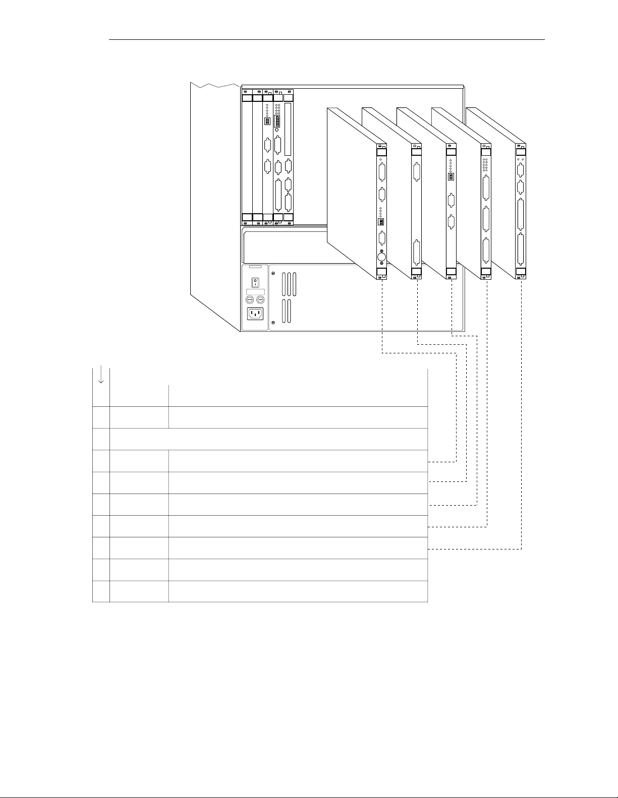
Adept MV-5 has
2 slots for optional
modules
Adept MV-10 has
7 slots for optional
modules
Adept MV-8 has
5 slots for optional
modules
Optional Modules
SIO
030
1
2
3
4
ON
2
3
41
OK
6
7
D
85
R
I
V
E
A
F
P
/
M
C
P
VGB
VIS
030
®
MI6
DIO
Adept MV-19 has
16 slots for optional
adept
technology, inc.
modules
Slots
Required
Standard Modules - installed in all Adept MV controllers
System
1
Processor
System
2
Input/Output
030 - 40 MHz 68030. 2, 4, or 8 MB RAM. 32 MHz 68882. or...
040 - 25 MHz 68040, 4 or 8 MB RAM.
SIO - floppy drive, hard drive, 3 serial I/O ports, 20 digital I/O
channels - 12 inputs, 8 outputs*
Optional Modules
Graphics
1
Module
AdeptVision
1
Interface
Auxiliary Sys.
1
Processor
AdeptMotion
1
Interface
Digital
1
Input/Output
AdeptForce
1
Interface
Adept Joint
1
Interface
*10 inputs, 5 outputs on Adept robots with MMSP option.
VGB - graphics processor, frame buffer, A-Series color video output 1024 x 768, keyboard/trackball input
VIS - vision framegrabber, 640 x 480 pixels, supports up to 4 cameras
and 2 strobes
030 or 040 - 3 modules max per controller, same specs as main
system processor
MI6 - 6 axes motor control per module, up to 4 modules in MV-10/19
MI3 - 3 axes motor control per module
DIO - 64 channels - 32 input/32 output, 2 output ranges - 10-15VDC
and 15-30VDC, 400 mA max output, 8 modules max per controller
VFI - interface to force-sensing unit, part of AdeptForce VME product,
includes 6-axis force/torque sensing, guarded moves, data collection
VJI - interface to Adept robots and power chassis, interface to belt
encoders for conveyor tracking.
(not shown above)
(not shown above)
Figure 2-2. Ade pt MV Co ntroller Configu ra tion
Adept MV Controller User’s Guide, Rev C 17
Page 40

Chapter 2 - Overview
Adept VME Joint Interface Module (VJI)
The Adept VME Joint Interface module (VJI) is required when an A dept robot, such as t h e
Adept 550, AdeptOne , or AdeptThree robot, is installed in an Adept MV controller
system. The VJI module interfaces to the encoders and amplifiers for the robot. Also, the
VJI is the interface to belt encoders in conveyor tracking applications for Adept robots.
AdeptForce VME Module (VFI)
The AdeptForce VME module (VFI) is part of the AdeptForce VME product. Other
components included in the product are the AdeptForce VME software module and the
force-sensing unit installed on a robot. See the product description later in this chapter for
more information.
1
Digital Input/Output Module (DIO)
The Adept Digital Input/Out put module (DIO) is a 64-chann el digit al I/O module w ith
32 input channels and 32 output channels. It is a 6U VME slave module and all inputs and
outputs are optically isolated. Up to 8 DIO modules can be installed in an Adept MV-19
controller, depending on slot availability. The total I/O capacity (including the channels
on the SIO module) of a contro ller with 8 DIO modules is 268 input channels and 264
output channels.
Auxiliary Processor
The Adept 030 and 040 System Processor modules can be used as Auxiliary System
processors to add increased processin g performance to an Adept system. An Auxiliary
processor can be assig ned to handle the processi ng ope rations for Ade p tMotion VME,
AdeptVisi on VME, Force-Se nsing, or, with the optional V
can run multiple instances of the V
used to specify which portions of the system software are handled by each processor.
+
operating system. The CONFIG_C utility program is
+
Extensions Software License,
1
For installations in Europe, see the Manufacturer’s Declaration (inside front cover) for
important EMC information. In applications using the VFI module, it may be necessary
to use additional EMC procedures, such as installing the controller in an EMI/FRI
shielded enclosure.
18 Adept MV Controller User’s Guide, Rev C
Page 41

2.6 Optional Equipment
External Front Panel (VFP-1 or VFP-3)
The external Front Panel (VFP) is a separate control panel that can be added to any Adept
MV controller system. There a r e two types of VFPs: the VFP-1 an d the VFP-3. The VFP-1 is
used with all Adept systems that do not include the Manual Mode Safety Package
(MMSP) option. The VFP-3 is used with syste ms that do have the MMSP option installed.
The VFP connects by cable to the front of th e SIO module. The VFP gives you comp lete
control over the Adept MV controller including Auto/M a nual mo de selec tion and
push-but ton E mer gen cy S top s witc h. Th e VFP ca n als o be use d to con tr ol AC pow er t o the
controller; on the MV-5 and MV-10 controllers this feature requires a user-supplied 24V
power supply and AC contact or. The optional Manual Control Pendant can be connected
to the VFP. (See page 96 for more information.)
Manual Control Pendant (MCP)
The Manual Control Pendant (MCP) is a hand-held cont rol unit that can be added to any
Adept MV controller system that includes a VFP. The MCP connects to the front of the
VFP. The MCP is available in two versions: the operator’s pendant and the programmer’s
pendant. The operator’s pendant has a palm-activated Hold-to-Run switch connected to
the r e mote emerg ency stop ci rcuit; th e progra mmer’s pendant does not have th is switch.
(The programmer ’s pendant cannot be used in installations that require CE Marking, for
example, in EU countries. Users should check local and national standards and laws.)
Optional Equipment
The MCP is often used to manual ly contro l a robot or moti on device during system
development. The MCP includes function keys and a 2-line by 40-character LCD display
that are f u lly programmable. An Emergency Stop push bu tton switch on the MC P shu ts
off high power at the Adept MV controller. See Appendix D on page 179 for complete
information.
AdeptNet
AdeptNet is Adept’s Ethernet networking solution for the Adept MV controller.
AdeptNet allows multiple Adept MV controllers to operate as nodes on a Local Area
Network (LA N) that may include other non- Adept devic e s such as PCs or UNIX-b a se d
workstations. AdeptNet software allows for peer-t o-peer communications, file transfer,
and sharing of a (non-Adept) file server. The AdeptNet hardware module requir es an 040
System Processor. These two modules are installed side-by-side in the MV controller.
A-Series Color Monitor
For the A-Series Adept MV controller, Adept offers an optional high-resolution color
monitor with a tilt/swivel base. The monitor has a maximum resolution of 1024 dots
horizontal by 768 lines vertical.
A-Series Extended Keyboard
For the A-Series Adept MV controller, Adept offers an optional extended keyboard with
an integrated trackbal l.
Adept MV Controller User’s Guide, Rev C 19
Page 42

Chapter 2 - Overview
Third-Party Terminals for an S-Series Controller
For S-Series Adept MV controllers, the user must supply a terminal to interface to the
controller. The terminal must be a Wyse model 60 or 75 with an
compatible terminal and keyboard.
2.7 Product Descriptions
AdeptVision VME
AdeptVision VME is a combination hardware and sof tware package for integrated
machine vision inspection and guidance applications. The hardware is based on an
A-Series Adept MV controller with an AdeptVi sion VME module (VIS) and an Adept
Graphics module (VGB) ins talled . Adep tVision VME can be integr ated int o any Adept
autom ation sy s t e m.
keyboard, or a
ANSI
AdeptVisi on VME is a high resolution, gray-scale visio n system based on Adept’s
multi-tasking V
extensive vision tools for vision-related operations like image capture, enhancement, and
analysis . AIM VisionWare software is included with the AdeptVision VME product.
+
language and operating system . V+ is a high level language with
AdeptMotion VME
AdeptMotion VME is a combination hardware and software package for motion control of
both simple and complex robots and other factory mechanisms. The hardware consists of
an Adept MV controlle r with one or several AdeptMotion Interfac e modules (MI3/MI6)
installed. The AdeptMotion VME control software runs on the V
product can be integrated into an Adept automation system with additional features such
as: vision guidance and in sp ection, conveyor track ing, and AIM software.
+
operating sy ste m. This
AdeptForce VME
AdeptFor ce is a hardware and sof tware package that allows Adept- controlled robots to
react to sensed forces and moments. Tight integration of the force sensor to the robot
control system dramatically reduces r ob ot stopping time when for ces or moments exceed
preset thresholds. As a result, assembly operations can be performed at higher speeds
than are possible with other force sensing units.
The hardware consists of an AdeptForce VME module (VFI) installed in the Adept MV
contr oller, and the force-sensi ng unit installed on th e robot. See the AdeptForce VME User’s
Guide for comp lete information on this product.
20 Adept MV Controller User’s Guide, Rev C
Page 43

Installation for MV-5 and
MV-10 Controllers 3
3.1 Shipping, Storage, Unpacking and I n s pection
3.2 Controller ID Label
3.3 Facility Requirements
3.4 Connecting AC Power (MV-5 an d MV-10)
3.5 Fuse Informatio n (MV -5 a n d MV-10)
3.6 Fan and Filter Informa tion
3.7 Removing and Installin g Modules
3.8 Installing the A-Series Monit or and Keyboar d
3.9 Installing a Terminal in an S-Se rie s S yst em
3.10 Installing a Stand-A lone Controller in a Rack o r Pan e l
3.11 Installing a Robot Controller in a Rack or Panel
3.12 MV-5 and MV-10 Controller Technical Speci fications
. . . . . . . . . . . . . . . . . . . . . . . . . . .
. . . . . . . . . . . . . . . . . . . . . . . . . .
. . . . . . . . . . . . . . . . . .
. . . . . . . . . . . . . . . . . . . . . . . .
. . . . . . . . . . . . . . . . . . . .
. . . . . . . . . . . . . .
. . . . . . . . . . . . . . . .
. . . . . . . . . . . . . .
. . . . . . . . . . . . . . . .
. . . . . . . . . . . .
. . . . . . . . .
. . . . . . . . .
22
22
23
24
28
29
30
34
36
37
39
41
Adept MV Controller User’s Guide, Rev C 21
Page 44

Chapter 3 - Installation for MV-5 and MV-10 Controllers
3.1 Shipping, Storage, Unpacking and Inspection
Shipping and Storage
This equipment must be shipped and stored in a temperature controlled envir onment,
within the range -25°C to +55°C. The recommended humidit y range is 5 to 90%,
non-condensing. It should be shipped and stor ed in the A dept-supplied packagin g, which
is designed to prevent damage fr om normal shock an d vi b ration. You should protect the
package from excessive shock and vibration.
Before Unpacking
Carefully inspect all shipping crates for evidence of damage during transit. Pay special
attent ion to tilt and shock indication labels on the exteriors of the containers. If any
damage is indicated, request that the carrier’s agent be present at the time the containe r is
unpacked.
Upon Unpacking
Compare the actual items received (not just the packing slip) with your equipment
purchase order and veri fy that all items are present and that the shipment is correct.
Inspect each item for external damage as it is removed from its container. If any damage is
evident, contact Adept at the numbers listed in Chapter 1.
Retain all con tain ers an d pac kag ing m ateri als. Thes e ite ms may b ecome neces sar y to set tle
claims or, at a later date, to relocate equipment.
Repacking For Relocation
If the cont roller needs to be reloc a te d, reverse the steps in the installati on proced u res that
follow this section. Re-use all original packing containers and materials and follow all
safety note s used for inst allation. Improper packaging for shipme nt will void your
warranty.
3.2 Controller ID Label
The identification ( ID) label is located on the left or bac k side of the con troller chas sis. On
it you will find the model and serial numbe rs an d the volt ag e and current ratings . A
smaller serial number la bel is also located on the fron t of the chassis near the On/Off
switch (see Figure 3-1). Yo u should always have this ser i al number available when you
call Adept Customer Service for technical support.
22 Adept MV Controller User’s Guide, Rev C
Page 45

3.3 Facility Requirements
The Adept MV controller is intended for use with other equipment and is considered a
sub-assembly rather than a complete piece of e quipment on its own. The Adept MV
controll er meet s th e requirements of EN 60204-1, IEC 1131-2, IEC 73, and IEC 447 safety
standards. To maintain complian ce with these standards, the controller must be installed
and used properly with any additional equipment in strict accordan ce with all
requirem e n t s o f these st a n da rds. For mo re i nf ormation ab o u t sa f e ty and sta n d ards
compliance, see section 1.3 on page 4, section 1.4 on page 7, and Appendix C.
The Adept MV controller installation must meet the environmental and electrical
requirements shown in Table 3-1 and Table 3 -2.
Table 3-1. Operating Env i ronment Requir em en ts
Ambient temperature
Facility Requirements
controller – while accessing floppy or
hard drive
controller – while not accessing floppy or
hard drive
Humidity 5 to 90%, non-condensing
Altitude up to 2000 m (6500 ft.)
Pollution degree 2
Free space around contr oll er (for proper
cooling)
Chassis protection class, unmounted IP20 (NEMA Type 1)
Recommendations for customer-supplied
enclosure with Adept controller mounted
inside enclosure. (These are mandatory for
installations in EU countries or where CE
marking is required.)
a
See footnote on page 18 if you are using the optional VFI module.
5°C to 40°C (32 to 104°F)
5°C to 50°C (32 to 122°F)
- Robot controller, vertical mounting:
25 mm at top and bottom
- Stand-alone controller, horizontal mounti ng:
25 mm at left and right sides
Enclosure must meet EN 60204-1 (I EC 204-1)
requirements (section 5.3.3) and be rated at
IP54. Also, enclosure must provide a method
of locking the enclosure power-disconnect in
the OFF position.
a
NOTE:
and MV-10 controll ers.
Refer to Appendix A for dimension drawings on the Adept MV-5
Voltage Interruptions
During a power failure, the contents of memory are not saved, and you will later have to
reload V
provide an external uninterruptable power supply (UPS) to avoid or reduce power
interruptions.
+
and your progr ams f r om disk . In some sit uati ons, you may find i t conv enien t to
Adept MV Controller User’s Guide, Rev C 23
Page 46

Chapter 3 - Installation for MV-5 and MV-10 Controllers
3.4 Connecting AC Power (MV-5 and MV-10)
The Adept MV-5 and MV-10 controllers have auto-r an ging power supplies that operate at
either 100-120 VAC or 200-240 VAC single phas e.
AC Power Requirements
Table 3-2. Adept MV Controller Power Requirements
Auto-Ranging
Nominal
Voltage Ranges,
Minimum
Operating
Voltage
a
Maximum
Operating
Voltage
Frequency/
Phasing
Recommended
External Circuit
Breaker
(user-supplied)
100V to 120V
and
200V to 240V
Power to the Adept MV controller and all amplifier s and mo tio n devic es m ust come f rom
a single so u rce .
a
The maximum interruption time (operating voltage belo w specificati on) tolerat ed by the
controller is 16 milliseconds.
If the Adept MV Controller is used with an Adept robot, see the robot user’s guide or
instr uction handbook for additional power require me nts.
Facility Overvoltage Protectio n
The user must protect the controller from excessive overvoltages and voltage spikes. In
particular, if the country of installation requires a CE-certified installation, or compliance
with IEC 1131-2, the following information may be helpful.
IEC 1131-2 requires that the installation must ensure th at category II overvolta ges (i.e.,
line-spikes not directly due to lightening str ikes) are not exceeded. Transient overvoltages
at the point of connection to the power source shall be controlled not to excee d
overvoltage category II, i.e. not higher than the impulse voltage corresponding to the
rated voltage for the basic insulation. The user-supplied equipment or transient
suppre ssor shall be cap ab le of absorbing the energy in the transient.
90V
180V
132V
264V
50-60Hz,
1-phase
10 amps
In the industrial environment, non-periodic overvoltage peaks may appear on mains
power supply lines as a result of power interruptions to high en ergy equipment (such as a
blown fuse on one branch in a 3-phase system). This will cause high current pulses at
relatively low voltage l evels. The user shal l take t he nec essa ry st eps to prevent damage to
the contr ol ler system (such as by interposing a transformer). See I EC 1131-4 for additional
information.
24 Adept MV Controller User’s Guide, Rev C
Page 47

Connecting AC Power (MV-5 and MV-10)
Power Entry Module
The power en try module is loc a ted on the front of the controller. It contains:
I
• the On/Off power switch (
• the fuse holder containing the two incom ing AC line fuses (spare fuses are stored
in the fuse holder, see Figure 3-4.)
• the AC power cord socket
= On, o = Off)
On/Off Switch
Fuse Holder
AC Power Cord
USE ONLY WITH
250V FUSES
WARNING:
FOR CONTINUED PROTECTION
AGAINST RISK OF FIRE,
REPLACE ONLY WITH SAME
TYPE AND RATING OF FUSE.
5AT
~100-240V
50/60HZ
®
Socket
Serial Number
Fan Filter Cover
Figure 3-1. MV-5/MV-10 Power Entr y Mo du le
Function of VFP System Power Switch with MV-5 and MV-10 Controllers
This section describes how to use the System Power switch on the External Front Panel
(VFP) when connected to an MV-5 or MV-10 controller.
Remote System Power Option
The External Front Panels, VFP-1 and VFP-3, include support for controlling system
power on the MV-5 and MV-10 controllers. If you want to use this feature, you must
provide an AC contactor (with 12V o r 24V coil, eithe r AC or DC coil, limite d to less than
500 mA.) See the draw ings on the next two pa ges for connecti on details.
• For the VFP-1, the user connection for System Power is at the terminal block (pins
1 and 2) on the back of the VFP. You will need to pr ovide a power supp ly to match
the coil voltage of the external contactor.
• For the VFP-3 in a n MMSP syst em, the us er con nect i on is l oca ted on t ermi nal block
TB5 (pins 5 and 6) on the Security Panel. I f you are using a contactor with a 24 V
DC coil, you can obtain 24VDC from terminal block TB1, pins 1 and 2, on the
Security Panel. I f your contactor is n ot 24VDC, you must pr ovide a suitable power
supply.
If you choose not to use this feature, the VFP System Power switch will not work. The
controller power will be controlled only by the switch on the power entry module.
Contact Adept C us tomer Service if you hav e any questions about this installation.
Adept MV Controller User’s Guide, Rev C 25
Page 48
Chapter 3 - Installation for MV-5 and MV-10 Controllers
040
SIO
STP
SF
1
OK
2
SCR
A
ESTOP
3
ACC V
C
B
4
SCSI
ON
VME
D
2
3
41
OK
6
7
D
85
R
I
RESET
V
E
A
F
P
/
ABORT
M
C
P
RESET
R
R
S
R
S
2
S
4
3
2
2
2
3
2
2
#1
R
S
2
I
3
/
2
O
R
2
S
4
2
V
3
E
2
T
1
/
H
0
T
E
0
E
R
m
R
N
A
M
E
T
#2
VJI
VGB
VIS
DIO
FAIL PASS
HPE
ES
OK
2
1
4
3
V
V
6
5
I
D
E
O
B
U
S
M
O
N
I
T
O
R
1
2
3
4
2
3
41
P
O
I
N
T
E
R
KEYBOARD
I
I
N
D
P
E
U
O
T
S
B
U
S
I
N
P
U
T
S
AMPLIFIER
SIGNAL
O
ON
U
T
P
U
T
S
BELT
ENCODER
C
A
M
O
E
U
R
T
A
P
S
U
/
T
S
S
T
R
O
B
E
ARM
S
SIGNAL
®
USE ONLY WITH
WARNING:
250V FUSES
FOR CONTINUED PROTECTION
AGAINST RISK OF FIRE,
REPLACE ONLY WITH SAME
TYPE AND RATING OF FUSE.
5AT
~100-240V
50/60HZ
Adept MV-5 or MV-10 Robot Controller
(example shown: MV-10)
External Front Panel (VFP-1)
MANUAL AUTO
LOCAL
NETWORK
O
SYSTEM
POWER
PROGRAM
START
I
LAMP
TEST
®
PENDANT
Pins 1 and 2 of terminal
block on VFP-1
HIGH POWER
ON/OFF
EMERGENCY STOP
PROGRAM
RUNNING
Coil
Usersupplied
24V Power
Supply
+
–
+
–
User-supplied
Contactor
L
AC Supply
N
(100-240VAC)
PE
Figure 3-2. Installation of User-Supplied Exter n al Contacto r an d Power Supply using VFP-1
26 Adept MV Controller User’s Guide, Rev C
Page 49
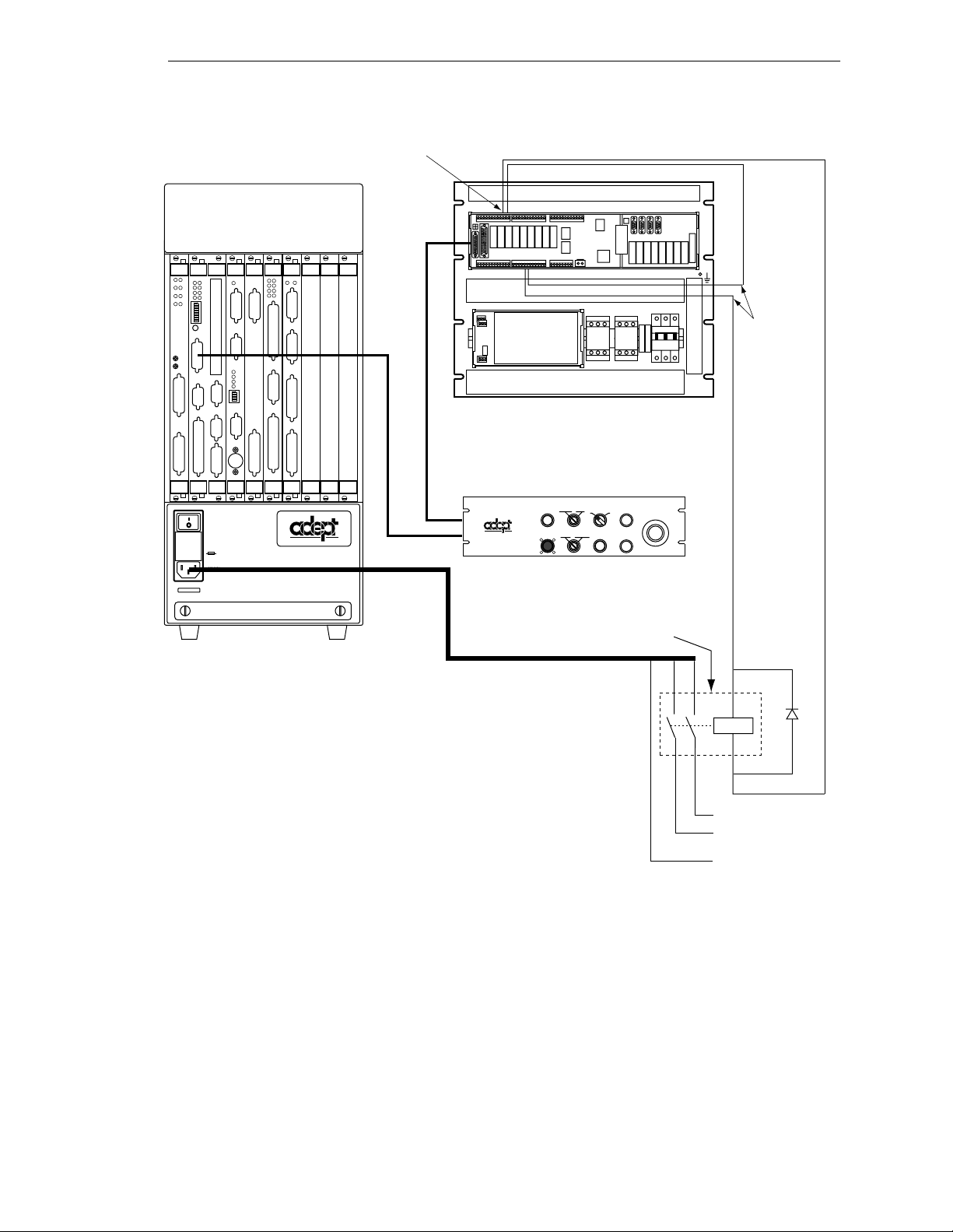
24VDC power (1 amp max) available
at TB1, pins 1 and 2
+
–
Connecting AC Power (MV-5 and MV-10)
040
SIO
STP
SF
1
OK
2
SCR
A
ESTOP
3
ACC V
C
B
4
SCSI
ON
VME
D
2
3
41
OK
6
7
D
85
R
I
RESET
V
E
A
F
P
/
ABORT
M
C
P
RESET
R
R
S
R
S
2
S
4
3
2
2
2
3
2
2
#1
R
S
2
I
3
/
2
O
R
2
S
4
2
V
3
E
2
T
1
/
H
0
T
E
0
E
R
m
R
N
A
M
E
T
#2
VJI
VGB
VIS
DIO
FAIL PASS
HPE
ES
OK
2
1
4
3
V
V
6
5
I
D
E
O
B
U
S
M
O
N
I
T
O
R
1
2
3
4
ON
2
3
41
P
O
I
N
T
E
R
KEYBOARD
I
I
N
D
P
E
U
O
T
S
B
U
S
I
N
P
U
T
S
AMPLIFIER
SIGNAL
O
U
T
P
U
T
S
BELT
ENCODER
C
A
M
O
E
U
R
T
A
P
S
U
/
T
S
S
T
R
O
B
E
ARM
S
SIGNAL
®
USE ONLY WITH
WARNING:
250V FUSES
FOR CONTINUED PROTECTION
AGAINST RISK OF FIRE,
REPLACE ONLY WITH SAME
TYPE AND RATING OF FUSE.
5AT
~100-240V
50/60HZ
Adept MV-5 or MV-10 Robot Controller
(example shown: MV-10)
TB5
MMSP Security Panel
External Front Panel (VFP-3)
SYSTEM
NETWORK
O
POWER
PROGRAM
HIGH POWER
ON/OFF
I
PROGRAM
RUNNING
START
LAMP
MANUAL AUTO
TEST
®
PENDANT
LOCAL
User-supplied
Contactor
To pins 5
and 6 of
terminal
block TB5
on E-Stop
Board
EMERGENCY STOP
+
Coil
–
L
AC Supply
N
(100-240VAC)
PE
Figure 3-3. Installation of User-Supplied External Contactor u si n g VFP-3
Connecting AC Power Cord
The AC power cord is included in the accessory kit. The controller end of the power cord
is fitted with an IEC 320 connector. The user end of the cord is unterminated. Connect
each conductor of the power cord securely to your AC power source, using the color code
below. You must provide a suitable plug or other facility connection in accordance with all
applicable local and national codes. See the next section for important information on
syste m g rou nding.
Adept MV Controller User’s Guide, Rev C 27
Page 50
Chapter 3 - Installation for MV-5 and MV-10 Controllers
Table 3-3. Power Cord Specifications
Cord length 3 meters ±0.1 m (9 ft . 1 0 in. ±4 in.)
Cord rating 10 amps
Number and size of
conductors
Color code
3 x 1.00 mm
2
line
neutral
ground
brown
blue
green/yellow
System Grounding Information
The detachable three-w ire pow er cor d is used for connection to both the power sour ce an d
protective ground. T he protective ground conductor (colored green/yellow) in the power
cord is internally connected to the exposed metal parts of the MV Controller. To ensure
electr ical-shock p rotection, the protective g round conductor must be connected to a
properly grounded power source.
WARNING:
before turning on the power.
Ensure that a proper protective ground connection exists
3.5 Fuse Information (MV-5 and MV-10)
The two fuses (F 1 and F2) at the power entry module on the front panel are for the
incoming AC power lines. See the table below for ratings.
WARNING:
change any fuses. Always replace blown fuses with new fuses of the same
type and rating.
Only skill e d or instructed personnel should atte mpt to
Procedure to Remove Fuse Holder
1. Turn off AC power to the controller and disconnect the power cord from the AC
power source.
2. Remove the AC power cord from the socket on the power entry module.
3. To remove the fuse holder, insert a small flat-b lade screwdriver into the slot
between the fuse holder and the power cord s oc ket, then lift up to release the fuse
holder; see Figure 3-4. Spare fuses are stored in the sliding compartments.
4. To reinstall the fuse holder, insert it in place, then press down firmly until the
entire holder snaps into position.
28 Adept MV Controller User’s Guide, Rev C
Page 51
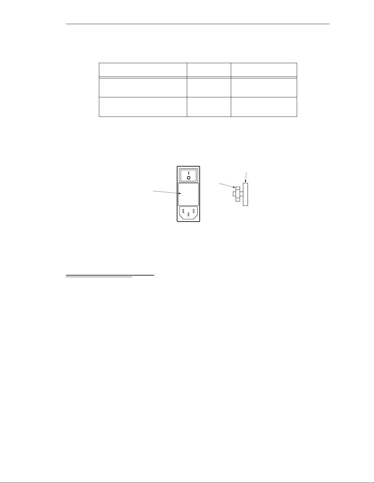
Fuse Ra tings
Tabl e 3-4. MV-5 and MV-10
Fuse Rating Type
Fan and Filter Information
F1 – AC Line fuse at Power
Entry module
F2 – AC Line fuse at Power
Entry module
5 AT/250 V IEC 127-style
5 x 20 mm
5 AT/250 V IEC 127-style
5 x 20 mm
NOTE: The “T” suf fix indicates the fuse re sponse time - a 5 AT fuse rating
specifies a 5 amp “slow blow” type.
Spare fuses
in sliding
compartment
Side view of
Fuse Holder
Fuse Holder
USE ONLY WITH
250V FUSES
Fuses
F1 and
F2
Figure 3-4.MV-5/MV-10 Fuse Holder
3.6 Fan and Filter Inf ormation
Cooling Fan
The chassis is cooled by an inte rnal fan in the chassis. On a robot control ler, the a ir intake
is through the bottom of the chassis and the exhaust is out through the top. On a
stand-alone controller, the air intake is through the right side of the chassis and the
exhaust is ou t through the left side.
Filter Inspection and Cleaning
The fan filter must be inspected at least once per month t o check for dirt and dust build up.
The fan filter is located behind the filter cover on the front of the controller (see
Figure 3-1). See Chapter 14 for information on inspecting and cleanin g the fan filter.
Adept MV Controller User’s Guide, Rev C 29
Page 52

Chapter 3 - Installation for MV-5 and MV-10 Controllers
3.7 Removing and Installing Modules
The Adept MV controller is shipped fr om the factory with al l the modules specifi ed on the
sales order installed in the chassis. Any unused slots are filled with blank covers. You may
want to add modules in the futu re or remove and re-install a module for some r e ason.
Additional modules should g e nerally be adde d to the chassis from left to righ t, starting
with the slot to the right of the last existing module. However, you can add any opti onal
module to any unused slot, in any order you like – as long as it is a valid configuration
(see section on backplane jumper plugs below). The VGB and VIS modules must be
installed side-by-side; also the 040 and NET modules must be installed side-by-si de. See
Chapter 2 for more details on r e quired and op tional modules .
CAUTION:
or removing modules or jumper plugs. Damage to the controller can
!!
!
occur i f th e con t roller is no t tu rned off.
CAUTION:
exposed to electro-static discharge (ESD) while you are handling or
storing them. Adept recommends using a ground strap on your wrist
when working with modules outside o f the contro ller. Use anti-static bags
to protec t modu le s w he n ou t s i de th e co ntroller.
Always turn off the controller power switch before installing
You must take precautions to prevent modules from being
VMEbus Address Settings
Each module in an Adept MV controller has a unique VMEbus address. All modules
installed in an Adept MV controller by Adept at the factory have the correct ad dress
already set when you r eceive the controller. If you add or change modules you need to
check the addresses of the new modules before installing them. The address setting for
each module is covered in the chapter i n th is manual f or that module .
Any modules that may have multiple units installed in one controller, such as the 030, 040,
VIS, MI6, MI3, DIO, or VJI must have a unique address for each of the individual
modules.
Upper Backplane Jumper Plugs (P1)
Jumper plugs are required next to any unused upper-backplane (P1) connectors. A
connector is unused when either:
• slot is empty (no module installed)
• module in adjacent slot is 2-slots wide (f or e xample, SIO) but only connect s to the
P1 connec tor in one slot.
On a typical controller, jumper plugs are factory-installed in slot 3 (or slot 4 in an MV-10
with an AdeptNet board installed). You do not have to do anything with jumper plugs
unless you change the position of the modules in the controller, then see the following
information.
30 Adept MV Controller User’s Guide, Rev C
Page 53
Removing and Installing Modules
Five user-supplied backplane jumper plugs must be installed on any unused slots in the
card cag e that are to the left of the last i nstalled module. Unused slots to the right of the
last installed module do not need jumper plugs. When you install a module into a
previously unused slot, you must first remove the five jumper plugs (if any are installed );
see Figure 3-5. Save the jumpers – if a module is moved to a different slot, you may need
to re-install the five jumper plugs onto the fi ve pairs of jumper pins on the backpl an e n ext
to the empty slot.
WARNING: Only skilled or instruc te d personnel should attempt to
change the backplane jumper plugs. This requires access to the interior of
the controller and potentially dangerous voltage may be present if the
power is n ot turned of f.
Lower Backplane Jumper Plugs (P2) and Third-Party Modules
The VMEbus standard defines some of the lower backplane (P2 bus) signals an d permits
other lines to be used for application-specific purposes. Adept uses several of these P2
user-signals for communication between Adept modules. These include some
safety-critical signals, incl u ding 24 V signals.
On the MV -5 an d MV-1 0, jumpers are provided next to each P2 connector. If a non-Adept
(third-party) module is installed in a slot, and that module uses the P2 (lower) connector,
the P2 user-signal jumpers for that slot must be remov e d.
If a thir d- part y VME module i s lat er remov ed fr om a sl ot, an d you plan to instal l an Ad ept
module in that slot, you must re-insta ll the P2 jumper plug s f or that slot.
WARNING: For safety and functional reasons, you must obtain approval
from Adept BEFORE adding third-party modules to the A dept controller.
An optional software license is also required. Please contact Adep t
Applications Engineering at the numbers listed on page 8.
Adept MV Controller User’s Guide, Rev C 31
Page 54
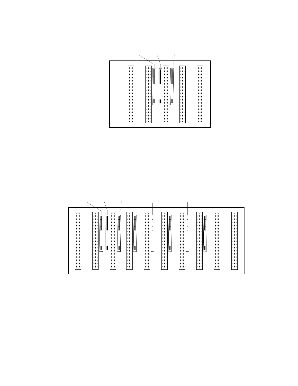
Chapter 3 - Installation for MV-5 and MV-10 Controllers
Jumper
location
for slot 4
Slot
3
No jumpers
required
for slot 5
Slot
4
Slot
5
P1 Backplane
Edge Connectors
for Adept MV-5
Jumper
location
for slot 2
Slot
1
Jumper
location
for slot 3
Slot
2
In a typical MV-5 system, jumper plugs are
factory-installed at slot 3.
Figure 3-5. Adept MV-5 Upper Backplane (P1) Jumper Plugs
P1 Backplane
Edge Connectors
for Adept MV-10
Jumper
location
for slot 2
Slot
1
Jumper
location
for slot 3
Slot
2
Jumper
location
for slot 4
Slot
3
Jumper
location
for slot 5
Slot
4
Jumper
location
for slot 6
Slot
5
Jumper
location
for slot 7
Slot
6
Jumper
location
for slot 8
Slot
7
In a typical MV-10 system, jumper plugs are
factory-installed at slot 3.
In an MV-10 system with an AdeptNet board installed in slot 2,
jumpers must be installed in slot 2 and slot 4.
Jumper
location
for slot 9
Slot
8
No jumpers
required
for slot 10
Slot
9
Slot
10
Figure 3-6. Adept MV-10 Upper Backplane ( P1) J u mper Plugs
32 Adept MV Controller User’s Guide, Rev C
Page 55

Removing Modules
1. T urn off the controller.
2. Loosen the captive screws at the top an d bottom of the module.
3. Lift up on the top handle and push down on the bo ttom handle as you start to
pull the module out of the c hassis. Re move the mod u le from the chassi s and store
it in a saf e p lace. (S ee p a g e 3 0 fo r a n ti - s t at i c precau tions. )
4. If the empty slot is not going to be used again and it is to the left of the last
installed module, you must install five user-supplied jumper plugs onto the five
pairs of jumper pins on the backplane. You can also fill the empty slot by moving
all module s on the right of the un us e d sl ot to the left.
Removing and Installing Modules
CAUTION:
turnin g off the po wer to the Adept MV Cont r oll er and all r elate d exte rn al
!
power supp lies. Fail ure to obse rve this caution could cause damag e to
your equipment.
Installing Modules
1. T urn off the controller.
2. If the slot has a blank panel installed, l oosen the captive screws at th e top and
bottom of th e pa n e l an d rem ove it.
3. Verify that the inten ded slot for the module is ready to accept the module. If the
slot has been unused, make sure ther e ar e no bac kplane jumper plugs install ed for
that slot; see Figure 3-5 or Figure 3-6.
4. Align the module with the card guide slots at the top and bottom of the card cage.
Slide the mo dule in slowly. Apply straight-forwa rd pressure to the two handles
on the outer edge of the module until it is firmly seated in the backplane
connector, and the face of the module i s flush with the other module s.
5. Tighten the captive sc rews at the top and bottom of the modu le.
CAUTION:
engage the connectors. If the board does not properly connect with the
!
backplan e , remove th e module and i nspect all connectors and guide slots
for possible damage or obstructions.
Do not attempt to install or remove any boards with ou t first
It should not be necessary to use excess pressure or force to
Adept MV Controller User’s Guide, Rev C 33
Page 56
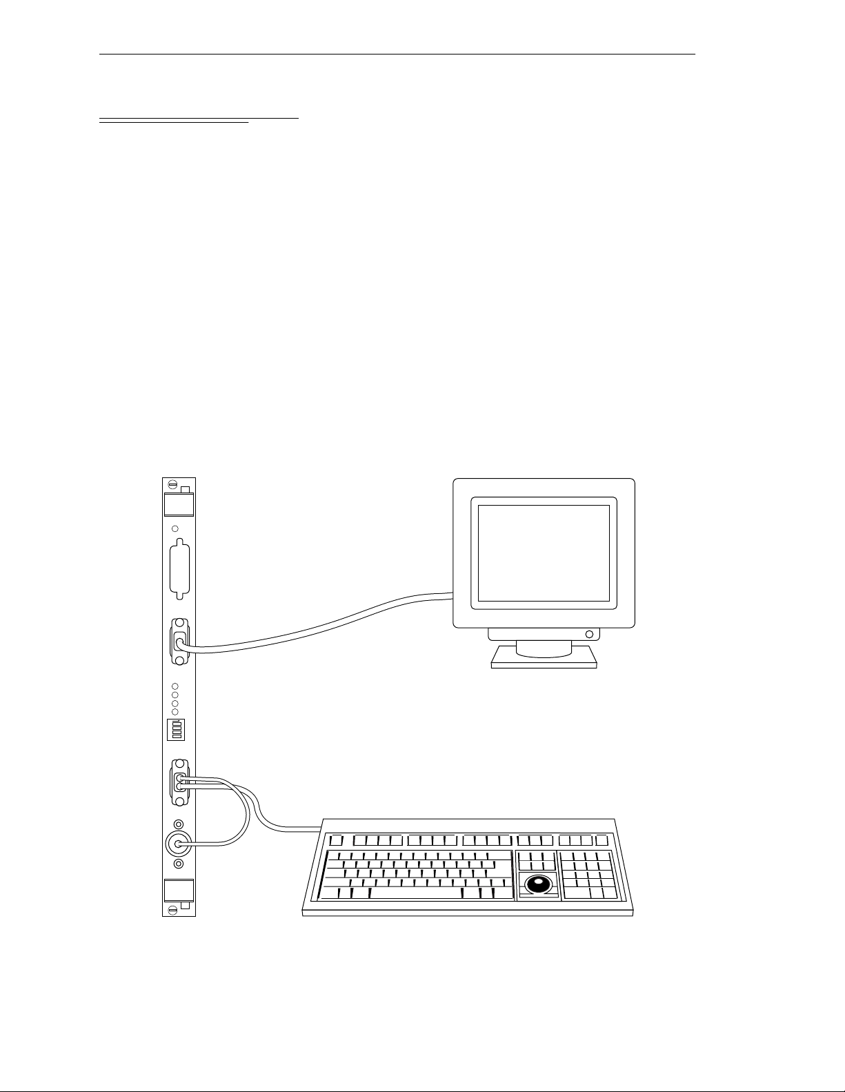
Chapter 3 - Installation for MV-5 and MV-10 Controllers
3.8 Installing the A-Series Monitor and K eyboard
NOTE:
The peripheral equipment such as the keyboard and monitor
supplied by Adept are intended for use in light industrial conditions. In
more severe conditions, they should be protected with a suitable
enclosure.
Installation Procedure
An A-Series Adept MV controller can be configured with a color monitor and an extended
keyboar d with b ui lt-i n tr ackb all. Bo th of t h ese d evi ces co n nect t o th e VG B modul e. See th e
+
Operating System User’s Guide for details on using the keyboard and trackball.
V
See Figure 3-7 for details; the steps are listed below.
1. Make sure the controller is turned off before making any connections.
2. Verify the voltage range marked on the monitor is compatible with your local
voltage source. Connect the color monitor AC power cord to the monitor, then
plug it into an appropriate voltage source.
VGB
OK
V
I
D
E
O
B
U
S
M
O
N
I
T
O
R
2
3
41
P
O
I
N
T
E
R
KEYBOARD
1
2
3
4
ON
A-Series Keyboard/Trackball
A-Series Color Monitor
Figure 3-7 . Connecting the A -S eries M o n i to r an d Keyboard
34 Adept MV Controller User’s Guide, Rev C
Page 57

Installing the A-Series Monitor and Keyboard
3. Connect the monitor signal cable to the
MONITOR
connector on the VGB
module.
4. Connect the double-ended keyboard cable to the
POIN TER
connector on the VGB module.
KEYBOARD
connector and the
Installing Non-Adept Peripherals in an A-Series System
You can use third-party monitors, keyboards, and pointing devices with an Adept MV
controller system. The equip me nt must be compati b le with certain standards to work
successfully with the Adept MV controller; see the following sections for details. Note that
the Adept-supplied monitor and keyboard are certified to meet the requirements of
EN 60204-1 and other international standards. Inst allation of a non-Adept perip her al may
not meet these standards.
Third-Party Monito r Co m p at ibility
If you ch oos e to use a col or mo nit or othe r th an t he o ne su ppl ied by Ade pt, you must make
sure the monitor meets the specifications shown in Tabl e3-5. Also, see Table 8-2 for the
pin assignments for th e monitor conne ctor on the VGB module.
Table 3-5. Monitor Compat ibilit y Sp ec ificat ions
Video Display Resolution 1024 x 768 pixels
Frame Rate 60 Hz
Format Non - i nt erlaced
Line Rate 48.363 kHz
Dot Rate 65.000 MHz
Video signal Analog RGB
Signal level 0 - 0.7 Vp-p
Input Impedance 75 ohm ±5% at 100 kHz
Third-Party Keyboard Compatibility
The Adept MV controller can interface to keyboards that are “AT” compatible and use a
standard DIN 5 connector. See Chapter 8 for the pin assignments on the connector.
Third-Party Pointing Device Compatibility
The Adept MV controller can interface to any mouse, trackball, or other pointing device
that uses the Micros oft mouse serial protocol (1200 bps). The connector must be a 9-pin
D-sub; the pin assignments are given in Chapter 8.
This port can alternatively be used for a touchscreen using ELO TouchSystems protocol.
See Chapter 8 for configuration an d com patibility. If you install a touchscreen, you must
disconnect the trackball (or mouse), you cannot use more than one pointing device.
Adept MV Controller User’s Guide, Rev C 35
Page 58

Chapter 3 - Installation for MV-5 and MV-10 Controllers
3.9 Installing a Terminal in an S-Series System
With an S-Series Adept MV controller system, the customer must supply the terminal a nd
cable to interface to the controller. The terminal must be a Wyse Model 60 or 75 with an
keyboard, or a compatible terminal. You may also be able to use a computer with
ANSI
suitable terminal emulation software. For DOS or Windows-compatible computers, the
programs “ProC o mm+” or “ProComm for Window s” (availa ble f rom many comp uter
stores) include software emulation for the Wyse-75.
Recommended Terminal for S-Series Systems
The recommended terminal for use wit h the A dept MV controller is the Wyse WY-60. You
must also specify that you require the Wyse ANSI/VT100 style keyboard (Wyse p/n
900127-02 or 900128-02). Note: Th e WY-60 is also available with ASCII and IBM Enhanced
PC keyboards. These are NOT Adept-compatible. You must make sure you order the
correct keybo ard. The WY-60 is avail able in both 220V and 110V confi g urations,
depending mainly on the country you buy it in.
Contacting WYSE
Wy se Technology, 3571 N. First St., San Jose, CA 95134, USA
Tel: USA: 1-800-GET-WYSE. Northern Calif.: (408) 473-1600
Internatio nal (par ti al list): GERMANY (0894)-600990, FRANCE (1) 69-82-91-00,
UK (01734)-342200, TAIWAN(238)-81306, SINGAPORE 254-5860.
All others, call USA (408) 473-1800
(Phone numbers correct as of July 1994. Source: Wyse USA)
Customer-Supplied Serial Interface Cable
A Wyse WY-60 ter min al has a 25-pin female D subm iniat ure connector (DB -25F), which
requires a 25-pin male connector (DB-25M) on the interface cable. The 030 module
RS-232/Term connector is a 9-pin male connector (DE-9P) which requires a 9-pin female
connector (DE-9F). See sec tion 5.3 for details on connecting a Wyse terminal to an 030
module. See sectio n 6.3 for in formation on connecting the 040 modu l e to a Wyse terminal.
If you are using a terminal other than a Wyse WY-60, check the documentation on the
serial connector before you purchase or build the serial interface cable.
Installation Procedure
1. Make sure the controller is turned off before making any connections.
2. Verify the voltage range marked on the terminal is compatible with your local
voltage source. Connect the AC power cord to the terminal, then plug it into an
appropriate voltage sourc e.
3. Connect a suitable serial cable between the terminal and the RS-232/Term
connector on the Syst e m P rocess o r module.
4. If the terminal is a Wyse 60, use the se tup mode to set the personality to
“WY-75”. If you are using terminal emulation software on a computer, set the
software to “WY-75” emulation. If “WY-75” is not ava ilable, try “VT102” or
“VT100”, but you will not be able to use all of the function keys.
36 Adept MV Controller User’s Guide, Rev C
Page 59

Installing a Stand-Alone Controller in a Rack or Panel
5. Set the baud rate to 9600, that is the default rate for the Adept system. To change
the baud rate, refer to the information on
Utility Programs.
CONFIG_C
in the Instruct ions fo r Adept
3.10 Installing a Stand-Alone Controller in a Rack or Panel
An MV-5 or MV-10 Stand-Alone controller can be mounted in a standard 19-inch
equipment rack using th e attached mounting brackets. The brac kets can also be moved to
the rear of the controller for panel mounting.
NOTE:
controller and all terminations at the controller must be performed in
accordance with thi s standard.
To maintain compliance with EN 60204-1, the mounting of the
Space Around the Chassis
When the Stand-Alone controller is installed, you must allow 25 mm (1 inch) at the left
and righ t sides of th e chassis for proper air cooling. You must also allow 75 mm (3 inches)
at the fr ont of the chassi s for power and signal cable clear ance.
CAUTION:
system can work efficiently. See Chapter 14 for details on cleaning the
!
filter .
The air filter must be kept clean so the forced air cooling
Rack Mounting
To rack mount the Adept MV-5 or MV-10 Stand-Alone controll er in a stan dard 19-inch
equipmen t rack, you must use the mounting brackets from the acce ssories kit. See
Figure 3-8 for instructions. See Appendix A for dimensions.
Side View of MV-5 or MV-10
Front
To install mounting brackets in rack mount
position:
• Remove 4 existing screws and washers
from side of chassis at locations shown
in drawing.
• Place bracket in position and secure
with same screws and washers removed
above.
• Repeat process for other side of controller.
Figure 3-8. Rack Mou n t in g for MV-5/MV-10 Stand-Alone Controller
Adept MV Controller User’s Guide, Rev C 37
Page 60

Chapter 3 - Installation for MV-5 and MV-10 Controllers
Panel Mounting
To panel mount the Adept MV-5 or MV-10 Stand-Alone controller, you must use the
mounting brackets and screws from the accessories kit. See Figure 3-9 for instructions.
Side View of MV-5 or MV-10
Front
Figure 3-9. Panel Mounting for MV-5/MV- 10 Stand-Alone Controller
To install mounting brackets in panel mount
position:
• Place bracket in position.
• Secure bracket with 3 screws and washers
from accessories kit at locations shown
in drawing.
• Repeat process for other side of controller.
38 Adept MV Controller User’s Guide, Rev C
Page 61

Installing a Robot Controller in a Rack or Panel
3.11 Installing a Robot Controller in a Rack or Panel
An MV-5 or MV-10 Robot controller can be mounted in a rack or panel by using the
mounting brackets that are shipped in the accessories kit. The brackets can be attached at
the rear of the controller for panel mounting or they can be attached to the front of the
controller for rack mounting.
NOTE:
controller and all terminations at the controller must be performed in
accordance with thi s standard.
To maintain compliance with EN 60204, the mounting of the
Space Around the Chassis
When the Rob ot co nt ro ller is i nst all ed, y ou mus t al low 25 mm ( inch ) at the t op an d bo ttom
of the chassis for proper air cooling. You must also allow 75 mm (3 inches) at the front of
the chassis for power and signal cable clearance.
CAUTION:
system can work efficiently. See Chapter 14 for details on cleaning the
!
filter .
The air filter must be kept clean so the forced air cooling
Rack Mounting
To rack mount the Adept MV-5 or MV-10 Robot controller in a standard 19-inch
equipmen t rack, you must first install the mounting brackets (se e Figure3-10), then build
an extender pane l and attach it to the bracket on one side of the controller.
The controller can be joined to an Adept PA-4 power chassis and mounted in a rack. Refer
to the do cu mentation that co me s wi t h the rob ot for in fo rmati o n .
Panel Mounting
To panel mount the Adept MV-5 or MV- 10 Rob ot controller, install one bracke t on each
side near the b a ck of the contr oller. Use the screws and washers from the accessories kit.
See Figure 3-10.
Adept MV Controller User’s Guide, Rev C 39
Page 62

Chapter 3 - Installation for MV-5 and MV-10 Controllers
To Install Mounting Brackets on MV-5 or MV-10
Robot controllers:
• Remove (and discard) 3 existing countersunk
screws from side of chassis at locations shown
in drawing.
• Place bracket in desired position and secure
with indicated M4 screws and washers from
accessories kit.
• Repeat process for other side of controller.
Note: See Appendix A for dimensions of the
controller and mounting brackets.
M4 x 25mm screw
(2 places)
M4 x 25mm screw
(2 places)
M4 x 10mm screw
Panel Mount
M4 x 25mm screw
(2 places)
M4 x 10mm screw
Rack Mount – Flush
Rack Mount – Set-Back
M4 x 10mm screw
Figure 3-10. Installing Mounting Brackets on MV-5 and MV-10 Robot Controller s
40 Adept MV Controller User’s Guide, Rev C
Page 63

MV -5 and MV-10 Controller Technical Specifications
3.12 MV-5 and MV-10 Controller Technical Specifications
Table 3-6. Technical Specifications for MV Controller
MV-5 MV-10
Input Voltage
DC Power Supply (total) 250 W 350 W
Dimensions See Appendix A
Operating Environment See Table 3-1
a
See Table 3-2 for complete information on input power and T able 3-4 for fuse ratings.
a
100-120 and 200-240 VAC,
auto ranging
100-120 and 200-240 VAC,
auto ranging
Adept MV Controller User’s Guide, Rev C 41
Page 64

Page 65

Installation for MV-8 and
MV-19 Controllers 4
4.1 Shipping, Storage, Unpacking and I n s pection
Shipping an d S torage
Before Unpacking
Upon Unpackin g
Repacking For Relocation
4.2 Controller ID Label
. . . . . . . . . . . . . . . . . . . . . . . . . . .
4.3 Facility Requirements
Voltage Interrup tion s
4.4 Connecting AC Po we r
AC Power Requirements
Facility Overvoltage Protection
Power Ent r y M o d u le
Connecting AC Power Cord
System Grounding Information
. . . . . . . . . . . . . . . . . . . . . . . .
. . . . . . . . . . . . . . . . . . . . . . . . . .
. . . . . . . . . . . . . . . . . . . . . . . . . .
. . . . . . . . . . . . . . . . . . . . . .
. . . . . . . . . . . . . . . . . . . . . . . . . .
. . . . . . . . . . . . . . . . . . . . . . . .
. . . . . . . . . . . . . . . . . . . . . . . . .
. . . . . . . . . . . . . . . . . . . . . . .
. . . . . . . . . . . . . . . .
. . . . . . . . . . . . . . . . . . . . . . . . .
. . . . . . . . . . . . . . . . . . . . .
. . . . . . . . . . . . . . . . . . . .
Changin g Voltage Settings (M V-8 and MV-19 )
4.5 Fuse Informatio n (MV -8 a n d MV-19)
4.6 Fan and Filter Informa tion
Cooling Fan
. . . . . . . . . . . . . . . . . . . . . . . . . . . . .
. . . . . . . . . . . . . . . . . . . . . . . .
Filter Inspection and Cleaning
4.7 Removing and Installin g Modules
. . . . . . . . . . . . . . . . . .
. . . . . . . . . . . . . . . . . . . .
. . . . . . . . . . . . . . . . . . . .
. . . . . . . . . . . . . .
. . . . . . . . . . . .
44
44
44
44
44
44
45
45
46
46
46
47
47
48
48
50
51
51
51
52
VMEbus Addres s Setti ng s
Backplane Jumper Plugs
Removing Modul es
Installing Modules
. . . . . . . . . . . . . . . . . . . . . . . . . .
4.8 Installing the A-Series Monit or and Keyboar d
4.9 Installing a Terminal in an S-Se rie s S yst em
4.10 Installing in a Rack or Pa nel Mo u nt
Space Around the Ch assi s
Panel Mounting
Rack Mounti ng
. . . . . . . . . . . . . . . . . . . . . . . . . . .
. . . . . . . . . . . . . . . . . . . . . . . . . . .
. . . . . . . . . . . . . . . . . . . . . .
. . . . . . . . . . . . . . . . . . . . . .
. . . . . . . . . . . . . . . . . . . . . . . . .
. . . . . . . . . . . . . .
. . . . . . . . . . . . . . . .
. . . . . . . . . . . . . . . . . .
. . . . . . . . . . . . . . . . . . . . . .
4.11 MV-8 and MV-19 Controller Technical Speci fications
Adept MV Controller User’s Guide, Rev C 43
. . . . . . . . .
52
52
54
54
54
54
55
55
55
55
57
Page 66

Chapter 4 - Installation for MV-8 and MV-19 Controllers
4.1 Shipping, Storage, Unpacking and Inspection
Shipping and Storage
This equipment must be shipped and stored in a temperature controlled envir onment,
within the range -25°C to +55°C. The recommended humidit y range is 5 to 90%,
non-condensing. It should be shipped and stor ed in the A dept-supplied packagin g, which
is designed to prevent damage fr om normal shock an d vi b ration. You should protect the
package from excessive shock and vibration.
Before Unpacking
Carefully inspect all shipping crates for evidence of damage during transit. Pay special
attent ion to tilt and shock indication labels on the exteriors of the containers. If any
damage is indicated, request that the carrier’s agent be present at the time the containe r is
unpacked.
Upon Unpacking
Compare the actual items received (not just the packing slip) with your equipment
purchase order and veri fy that all items are present and that the shipment is correct.
Inspect each item for external damage as it is removed from its container. If any damage is
evident, contact Adept at the numbers listed in Chapter 1.
Retain all con tain ers an d pac kag ing m ateri als. Thes e ite ms may b ecome neces sar y to set tle
claims or, at a later date, to relocate equipment.
Repacking For Relocation
If the cont roller needs to be reloc a te d, reverse the steps in the installati on proced u res that
follow this section. Re-use all original packing containers and materials and follow all
safety note s used for inst allation. Improper packaging for shipme nt will void your
warranty.
4.2 Controller ID Label
The identification ( ID) label is located on the left side of the controller chass is . On it you
will find the model and serial numbers and the voltage and current ratings. A smaller
serial n umber lab el i s als o loc ated on th e front of th e c hassi s ab ove the On /Of f s witc h. You
should always have this serial number available when you call Adept Customer Service
for technical support.
44 Adept MV Controller User’s Guide, Rev C
Page 67
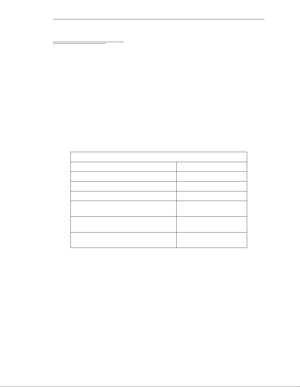
4.3 Facility Requirements
The Adept MV controller is intended for use with other equipment and is considered a
sub-assembly rather than a complete piece of e quipment on its own. The Adept MV
control l e r meet s th e requirements of EN 60204, IEC 1131-2, IEC 73, and IEC 447 safety
standards. To maintain complian ce with these standards, the controller must be installed
and used pr oper ly wit h any ad ditio nal equipmen t in str ict acc or danc e with al l r egu lation s
of the s tand ard s. For mo re i nf ormat ion about saf ety and st andar ds co mpli ance, see se cti on
1.3 on page 4, section 1.4 on page 7, and Appendix C.
The controller must be installed in a suitable enclosure, and you must provide a method of
locking the enclosure power-disconnect in the OFF position (such as padlocks). Refer to
section 5.3.3 of EN 60204.
The Adept MV controller installation must meet the environmental and electrical
requirements shown in Table 4-1 and Table 4 -2.
Table 4-1. Operating Env i ronment Requir em en ts
Facility Requirements
Ambient temperature
while accessing floppy or hard drive 5°C to 40°C (32 to 104°F)
while not accessing floppy or hard drive 5°C to 50°C (32 to 122°F)
Humidity 5 to 90%, non-condensing
Altitude up to 2000 m (6500 ft.)
Free space around contr oll er (for proper
cooling)
Controller sub-assembly protection class,
unmounted
Enclosure req uir ements to meet EN 602 04 and
EN 55011
NOTE:
and MV-19 controll ers.
Refer to Appendix A for dimension drawings on the Adept MV-8
50 mm (2") in front, 25 mm
(1") at top
IP20
(NEMA Type 1)
IP54
Voltage Interruptions
During a power failure, the contents of memory are not saved, and you will later have to
reload V
provide an external uninterruptable power supply (UPS) to avoid or reduce power
interruptions.
+
and your progr ams f r om disk . In some sit uati ons, you may find i t conv enien t to
Adept MV Controller User’s Guide, Rev C 45
Page 68

Chapter 4 - Installation for MV-8 and MV-19 Controllers
4.4 Connecting AC Power
The Adept MV-8 and MV-19 contro llers operate at either 100-120 VAC or 200-240 VAC
single phase. All controllers are shipped from the factor y set to 200-240 VAC single phase.
See Table 4-4 for details on changing to 100-120 VAC configuration.
AC Power Requirements
Table 4-2. Adept MV Controller Power Requirements
Nominal
Voltage
Range
Frequency/
Phasing
Minimum
Operating
Voltage
a
Maximum
Operating
Voltage
Recommended
External Circuit
Breaker
(user-supplied)
200V to 240V
(factory
setting)
100V to 120V
(user-config–
urable)
Power to the Adept MV controller and all amplifier s and mo tio n devic es m ust come
from a single source.
a
The maximum interruption time (operating voltage below specification) tolerated by
the controller is 16 milliseconds.
If the Adept MV Controller is used with an Adept robot, see the robot user’s guide for
additional power requirements.
Facility Overvoltage Protectio n
The user must protect the controller from excessive overvoltages and voltage spikes. In
particular, if the country of installation requires a CE-certified installation, or compliance
with IEC 1131-2, the following information may be helpful.
IEC 1131-2 requires that the installation must ensure th at category II overvolta ges (i.e.,
line-spikes not directly due to lightening str ikes) are not exceeded. Transient overvoltages
at the point of connection to the power source shall be controlled not to excee d
overvoltage category II, i.e. not higher than the impulse voltage corresponding to the
rated voltage for the basic insulation. The user-supplied equipment or transient
suppre ssor shall be cap ab le of absorbing the energy in the transient.
50-60Hz,
1-phase
50-60Hz,
1-phase
180V 264V 10 amps
90V 132V 10 amp s
In the industrial environment, non-periodic overvoltage peaks may appear on mains
power supply lines as a result of power interruptions to high en ergy equipment (such as a
blown fuse on one branch in a 3-phase system). This will cause high current pulses at
relatively low voltage l evels. The user shal l take t he nec essa ry st eps to prevent damage to
the contr ol ler system (such as by interposing a transformer). See I EC 1131-4 for additional
information.
46 Adept MV Controller User’s Guide, Rev C
Page 69
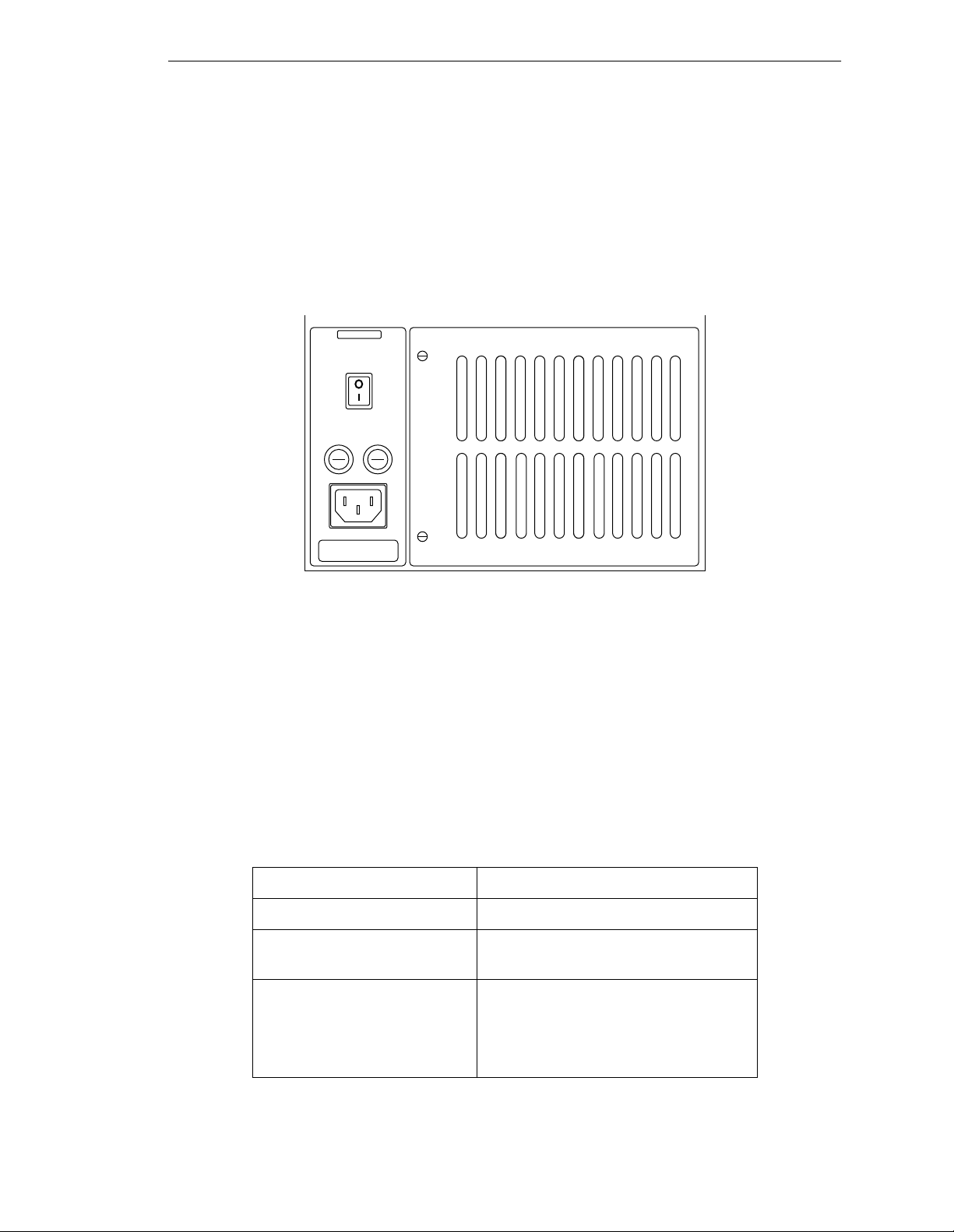
Connecting AC Power
Power Entry Module
The power entry module is located at the lower left side of the controller front panel. It
contains:
I
• the On/Off power switch (
• the AC power cord socket
• the two incoming AC line fuses
adept
technology, inc.
WARNING:
FOR CONTINUED
PROTECTION AGAINST RISK OF
FIRE, REPLACE ONLY WITH SAME
TYPE AND RATING OF FUSE.
= On, o = Off)
Figure 4-1. Power Entry Module
Connecting AC Power Cord
The AC power cord is included in the accessory kit. The controller end of the power cord
is fitted with an IEC 320 connector. The user end of the cord is unterminated. Connect
each conductor of the power cord securely to your AC power source, using the color code
below. You must provide a suitable plug or other facility connection in accordance with all
applicable local and national codes. See the next section for important information on
syste m g rou nding.
Table 4-3. Power Cord Specifications
Cord length 3 meters ±0.1 m (9 ft . 1 0 in. ±4 in.)
Cord rating 10 amps
Number and size of
conductors
Color code
line
neutral
ground
3 x 1.00 mm
brown
blue
green/yellow
2
Adept MV Controller User’s Guide, Rev C 47
Page 70
Chapter 4 - Installation for MV-8 and MV-19 Controllers
System Grounding Information
The detachable three-w ire pow er cor d is used for connection to both the power sour ce an d
protective ground. T he protective ground conductor (colored green/yellow) in the power
cord is internally connected to the exposed metal parts of the MV Controller. To ensure
electr ical-shock p rotection, the protective g round conductor must be connected to a
properly grounded power source.
WARNING:
before turning on the power.
Ensure that a proper protective ground connection exists
Changing Voltage Settings (MV-8 and MV-19)
To change the AC voltage setting from 200-240V to 100-120V, you must change three
jumper wires on the co nfiguration b lock and change three fuses. You should make this
change before installing the controller, because you must open the top of the controller to
get to the configu ratio n b l o ck .
WARNING:
change the AC voltage settings. This requires access to the interior of the
controller and potentially dangerous AC voltage may be present if the
power cord is not disconnected.
1. Make sure the controller is turned off. Disc onnect the AC power cord fro m the AC
power so urce, or from the front of the controller.
2. Remo ve the top co ver of the co ntroller by u n s cre wing four sc rew s on the top.
3. Open and fold down the back section of the controller by removing the upper two
screws on each side of th e back edge of the ch assis (see Figure 4-2). When the
screws are removed you can fold the back section down to make it easier to access
the configuration block, which is located inside the back of the controller near the
top.
Only skill e d or instructed personnel should atte mpt to
4. Change the jumper wires on the configuration block from the 200-240V to the
100-120V settings; see Table 4-4.
Table 4-4. Voltage Selectio n Jumper Settings
Operating
Voltage
200-240VAC 24 to 16 32 to 40 5 to 2
100-120 VAC 24 to 8 32 to 16 5 to 9
5. Change the two internal fuses F1 and F2 from the 200-240V to the 100-120V value;
see fuse information in Table 4-5 and on the label near the fuses – see Figure 4-3.
6. Close and secure the back p anel and install the top cover.
Jumper these pins together on the
Configuration Block.
48 Adept MV Controller User’s Guide, Rev C
Page 71
7. Change the two external fuses (F3 and F4) on the powe r entry module from the
200-240V to the 100-120V value; see fuse information in Table 4-5 and the label
below the power entry mod u l e.
8. Mark or alter the ID label to indicate the controller is now configured for
100-120 VAC.
9. Connect the AC power cord and the controller is ready to operate.
1 5 9 13 17 21 25 29 33 37
2 6 10 14 18 22 26 30 34 38
3 7 11 15 19 23 27 31 35 39
4 8 12 16 20 24 28 32 36 40
Numbering pattern on jumper block
Connecting AC Power
Remove these screws
(two on each side) to
fold down the back
panel.
F5
F2
F1
Configuration
Jumper Block
Figure 4 -2. Adept MV Controll e r w i t h B ack Pan el Open
Adept MV Controller User’s Guide, Rev C 49
Page 72
Chapter 4 - Installation for MV-8 and MV-19 Controllers
4.5 Fuse Information
The two fuses (F 3 and F4) at the power entry module on the front panel are for the
incoming AC power lines. There are three fuses (F1, F2, and F5) inside the back section of
the chassis, at the left side (looking from the fr ont) near the top (see Figure 4-3). See the
table below for ratings.
WARNING:
change any fus e s. F1, F2, and F5 r e quire acc e ss to the interi or of the
controller and potentially dangerous AC voltage may be present if the
power cord is not disconnected.
Always replace blown fuses with new fuses of the same type and rating.
The controller is shipped with IEC 127-style 5 x 20 mm fuses and fuse holders (black)
installed at F1, F2, F3, F4, and F5. Included in the accessories kit are five alternative fuse
holder inserts (gray) for 3AG-type (1/4" x 1 1/4") fuses.
Operating Voltage
➔
Only skill e d or instructed personnel should atte mpt to
(MV-8 and MV-19)
Tabl e 4-5. Fuse Ratings
MV-8 Chassis MV-19 Chassis
200-240 VAC 100-120 VAC 200-240 VAC 10 0-120 VAC
Fuse Location
F3, F4 – two AC Line fuses at
Power Entry module
(both the sa me)
F1, F2 – internal chassis, left
side as viewed from front
(both the sa me)
F5 – internal chas sis, right
side as viewed from front
NOTE:
example, a 2.5AF fuse r atin g speci fies a 2. 5 amp “fas t blow” type. A 1 .6AT
fuse rating specifies a 1.6 amp fuse, time delay (slow-blow) type.
Fuses F1 and F2 are rated to blow within 60 seconds if the current reaches
200% of the rated value. F u s e s F 3 , F4, and F5 are rated to b l o w withi n
5 seconds if the current reaches 200% of the rated value.
The “F” and “T” suffixes indicate the fuse response time. For
2.5 AF/250 V 5 AF/250 V 6.3 AF/250 V 8 AF/250 V
1.6 AT/250 V 2 AT/250 V 1.6 AT/250 V 2 AT/250 V
0.5 AF/250 V
50 Adept MV Controller User’s Guide, Rev C
Page 73
Top view with cover removed
Fan and Filter Information
F1
F2 F5
F1
F5
F2
Configuration
Jumper Block
Figure 4- 3. Inter n al F u se Locations
4.6 Fan and Filter Inf ormation
Cooling Fan
The chassis is cooled by a fan in the lower front section of the chas sis. The MV-8 has one
fan, the MV-19 has two fans. Air intake is through the lower front of the chassis an d th e
exhaust is ou t through the top.
Power Supply
Filter Inspection and Cleaning
The fan filters must be inspected at least once per month to check for dirt and dust
buildup. See Chapter 14 for information on inspecting an d cleaning the fan filter.
Adept MV Controller User’s Guide, Rev C 51
Page 74

Chapter 4 - Installation for MV-8 and MV-19 Controllers
4.7 Removing and Installing Modules
The Adept MV controller is shipped fr om the factory with al l the modules specifi ed on the
sales order installed in the chassis. Any unused slots are filled with blank covers. You may
want to add modules in the futu re or remove and re-install a module for some r e ason.
Additional modules should g e nerally be adde d to the chassis from left to righ t, starting
with the slot to the right of the last existing module. However, you can add any opti onal
module to any unused slot, in any order you like – as long as it is a valid configuration
(see section on backplane jumper plugs below). The VGB and VIS modules must be
installed side-by-side. See Chapter2 for more details on requir e d and optional mod u les.
CAUTION:
or rem ovi ng mod ule s. D ama ge to the co ntr o ller can oc cur if the controlle r
!!
!
is not tu rn ed off.
CAUTION:
exposed to electro-static discharge (ESD) while you are handling or
storing them. Adept recommends using a ground strap on your wrist
when workin g w it h mo d ules out s i de of the controlle r.
Always turn off the controller power switch before installing
You must take precautions to prevent modules from being
VMEbus Address Settings
Each module in an Adept MV controller has a unique VMEbus address. All modules
installed in an Adept MV controller by Adept at the factory have the correct ad dress
already set when you r eceive the controller. If you add or change modules you need to
check the addresses of the new modules before installing them. The address setting for
each module is covered in the chapter i n th is manual f or that module .
Any modules that may have multiple units installed in one controller, such as the 030, 040,
VIS, MI3, MI6, or DIO must have a unique address for each of the individual modules.
Backplane Jumper Plugs
Five user-supplied backplane jumper plugs must be installed on any unused slots in the
card cag e that are to the left of the last i nstalled module. Unused slots to the right of the
last installed module do not need jumper plugs. When you install a module into a
previously unused slot, you must first remove the five jumper plugs (if any are installed );
see Figure 4-4 and Figure 4-5. Save the jumpers – if a module is moved to a different slot,
you may need to re-install the five jumper plugs onto the five pairs of jumper pins on the
backplane next to the empty slot.
WARNING:
change the back plane jump er plugs . This r eq uir es acc ess to the inter ior of
the controller and potentially dangerous voltage may be present if the
power is n ot turned of f.
52 Adept MV Controller User’s Guide, Rev C
Only skill e d or instructed personnel should atte mpt to
Page 75

Removing and Installing Modules
f
Jumpers
for slot 4
P1 Backplane
Edge Connectors
or Adept MV-8
Figure 4-4. Adept MV-8 Backplane Jumper Plugs
Jumpers
for slot 4
Jumpers
for slot 5
Jumpers
for slot 5
Slot
4
Slot
5
Jumpers
for slot 6
Jumpers
for slot 6
Slot
6
Jumpers
for slot 7
Slot
7
Jumpers
for slot 17
No jumpers
required
for slot 8
Slot
8
Jumpers
for slot 18
P1 Backplane
Edge Connectors
for Adept MV-19
Slot
4
Slot
5
Slot
6
Slot
17
Slot
18
Jumpers for
slots 7 to 16
in same position
as slots 4 to 6.
Figure 4-5. Adept MV-19 Backplane Jumper Plugs
No jumpers
required
for slot 19
Slot
19
Adept MV Controller User’s Guide, Rev C 53
Page 76

Chapter 4 - Installation for MV-8 and MV-19 Controllers
Removing Modules
1. T urn off the controller.
2. Loosen the captive screws at the top an d bottom of the module.
3. Lift up on the top handle and push down on the bo ttom handle as you start to
pull the module out of the c hassis. Re move the mod u le from the chassi s and store
it in a safe place.
4. If the empty slot is not going to be used again and it is to the left of the last
installed module, you mu st install fi ve user-su p p lied jumper plu g s onto the fiv e
pairs of jumper pins on the backplane. You can also fill the empty slot by moving
all module s on the right of the un us e d sl ot to the left.
CAUTION:
turnin g off the po wer to the Adept MV Cont r oll er and all r elate d exte rn al
!
power supp lies. Fail ure to obse rve this caution could cause damag e t o
your equipment.
Installing Modules
1. T urn off the controller.
2. If the slot has a blank panel installed, l oosen the captive screws at th e top and
bottom of th e pa n e l an d remo ve it.
3. Verify that the inten ded slot for the module is ready to accept the module. If the
slot has been unused, make sure ther e ar e no bac kplane jumper plugs install ed for
that slot; see Figure 4-4 and Figure 4-5.
4. Align the module with the card guide slots at the top and bottom of the card cage.
Slide the mo dule in slowly. Apply straight-forwa rd pressure to the two handles
on the outer edge of the module until it is firmly seated in the backplane
connector, and the face of the module i s flush with the other module s.
5. Tighten the captive sc rews at the top and bottom of the modu le.
CAUTION:
engage the connectors. If the board does not properly connect with the
!
backplan e , remove th e module and i nspect all connectors and guide slots
for possible damage or obstructions.
Do not attempt to install or remove any boards with ou t first
It should not be necessary to use excess pressure or force to
4.8 Installing the A-Series Monitor and K eyboard
See section 3.8 on page 34 for installation information.
4.9 Installing a Terminal in an S-Series System
See section 3.9 on page 36 for installation information.
54 Adept MV Controller User’s Guide, Rev C
Page 77

4.10 Installing in a Rack or Panel Mount
The controller can be mounted in a rack or panel by using the mountin g bracket s that are
shipped in the accessories kit. The br ackets can be attached at the rear of the controller fo r
panel mounting or they can be attached to the front of the controller for rack mounting.
Installing in a Rack or Panel Mount
NOTE:
controller and all terminations at the controller must be performed in
accordance with thi s standard.
To maintain compliance with EN 60204, the mounting of the
Space Around the Chassis
When the controller is installed, you must allow 50 mm (2 inches) at the front of the
chassis and 25 mm (1 inch) at the top of the chassis for proper air cooling. The chassis
should be mounted in a vertical position for proper cooling flow.
CAUTION:
system can work efficiently. See Chapter 14 for details on cleaning the
!
Most service operations (filters and fuses) require access to the front of the controller.
However, to replace fuses F1, F2, and F5, qualified personnel will need to remove the
controller top cover. The controller may need to be removed from its mounting for this
procedure. Alternati ve ly, you may choose to leave su fficient space ab ove the controller, or
to install it on slide mounts.
filter .
The air filter must be kept clean so the forced air cooling
Panel Mounting
To panel mount either the Adept MV-8 or MV-19 controller, install one bracket on each
side near the b a ck of the contr oller. Use the screws and washers from the accessories kit.
See Figure 4-6.
Rack Mounting
To rack mount the Adept MV-19 controller in a standard 19-inch equipment rack, you
must use the mounting brackets, scre ws, and washers from the accessories kit. The
brackets can be installed in two posi tions for rack mounting: flush a nd se t-back. See
Figure 4-6 for details.
To rack mount the Adept MV-8 controller in a stand ard 19-inch equipment rac k, you must
first install the mounting brackets, then build an extender panel and attach it to the
bracket on on e side of the cont roller.
The Adept MV-8 controller can be joined t o an A dept PA-4 power chassis and mounted in
a rack. Refer to the documen tation that comes with the PA-4 for information.
Adept MV Controller User’s Guide, Rev C 55
Page 78

Chapter 4 - Installation for MV-8 and MV-19 Controllers
To Install Mounting Brackets:
• Remove (and discard) 3 existing countersunk
screws from side of chassis at locations shown
in drawing.
• Place bracket in desired position and secure
with indicated M4 screws and washers from
accessories kit.
• Repeat process for other side of controller.
Note: See Appendix A for dimensions of the
controller and mounting brackets.
M4 x 25mm screw
(2 places)
M4 x 25mm screw
(2 places)
M4 x 10mm screw
Panel Mount
M4 x 25mm screw
(2 places)
M4 x 10mm screw
Rack Mount – Flush
Rack Mount – Set-Back
Figure 4-6. In st allin g Mounting Brackets
56 Adept MV Controller User’s Guide, Rev C
M4 x 10mm screw
Page 79

MV -8 and MV-19 Controller Technical Specifications
4.11 MV-8 and MV-19 Controller Technical Specifications
Table 4-6. Technical Specifica tio ns for MV-8/19 Controllers
MV-8 MV-19
Input Voltage
DC Power Supply (total) 250 W 500 W
Power Available on Backplane
5 V 35 A max 80 A ma x
+12 V 8.0 A max 10.0 A max
–12 V 2.0 A max 10.0 A max
+24 V Used for internal Emergency Stop circuitry only
a
100-120/200-240 VAC 100-120/200-240 VAC
Dimensions See Appendix A
Operating Environment See Table 4-1
a
See Table 4-2 for complete information on input power and T able 4-5 for fuse ratings.
Adept MV Controller User’s Guide, Rev C 57
Page 80

Page 81

030 Processor Module 5
5.1 Introduction
5.2 Connections and Indicators
. . . . . . . . . . . . . . . . . . . . . . . . . . . . . .
. . . . . . . . . . . . . . . . . . . . . .
5.3 Serial I/O Connections, 030 Mo dule
RS-422/485 Connector (on 030 Module)
RS-232/Term Connector (on 030 Module)
Used in an S-Series System
Used in an A-Series System
Typical Cable Co nne cti o n s
Typical Cabl e Co nnec ti o n s, 9- pin to 25-pin (DCE)
Typical Cabl e Co nnec ti o n s, 9- pin to 25-pin (DTE)
Recommended Connections, 9-pin to 25-pin (Wyse WY-60 Terminal)
. . . . . . . . . . . . . . . . . . . . . . . . . . . . . .
Typical Cabl e Co nnec ti o n s, 9- pin to 9-p in (A T -Co m patible)
DTE, DCE, or AT-style?
5.4 Memory
5.5 VMEbus Address
5.6 030 Jumper Settings
. . . . . . . . . . . . . . . . . . . . . . . . . . . . . . . .
. . . . . . . . . . . . . . . . . . . . . . . . . . . .
. . . . . . . . . . . . . . . . . . . . . . . . . .
5.7 Use as an Auxiliary Pro ce ssor
. . . . . . . . . . . . . . . . . . . . .
. . . . . . . . . . . . . . . . . . . . . .
5.8 030 Processo r Mod u l e Specifi cations
. . . . . . . . . . . . . . . . . . .
. . . . . . . . . . . . . . .
. . . . . . . . . . . . . .
. . . . . . . . . . . . . . . . . .
. . . . . . . . . . . . . . . . . .
. . . . . . . . . . . . . . . . . .
. . . . . . .
. . . . . . .
. .
. . . . . . . . . . . . . . . . . .
60
60
61
61
62
62
62
63
63
64
64
65
66
67
67
68
69
69
Adept MV Controller User’s Guide, Rev C 59
Page 82

Chapter 5 - 030 Processor Module
5.1 Introduction
All Adept MV controllers require at least one system processor module; the module can
be an 030 or an 040. You can have bot h 030 and 040 modules i nstalled, up to a maximum
of 4 modules. The 030 is a single-slot 6U VM E module that can serve as the main system
processor for an Adept MV controller. The CPU for this module is a Motorola 68EC030
micropr ocessor running at 40 MHz. The module can be configur ed with 2, 4, or 8 MB of
DRAM. This module also includes a Motorol a 68882 math coprocessor. See the next
chapter for information on the 040 module.
The 030 has two serial I/O connectors on the front of the module: one is an RS-232 port
and the other is an RS-422/485 port. In an S-Series Adept MV controller, the
programmer’s terminal connects through the RS-232 port on the 030 module. (In an
A-Serie s co ntro l le r, the monito r an d k e yb o ard co nn ect to the Adept VGB modul e. )
The 030 can be used either as the main system processor, or as an auxiliary processor in
Adept MV controller systems; see section 5.7.
5.2 Connections and Indicators
➋
➌
➍
➊
R
S
4
2
2
/
4
8
5
R
S
2
3
2
/
T
E
R
M
030
2
3
41
#1
#2
➊
Status LED’s. When lit:
+
OK indicates thi s module has pas s e d V
OK
1
2
3
4
ON
1 - 4 are for Adept Service use only.
➋
DIP Switch (4 position) –
1, 2, 3 are not use d and should be set to OFF.
start-u p te st.
4 is for Adep t in ternal use only and should be set to OFF.
➌
RS-422/485 connector – for general serial communication.
➍
RS-232/Term connector – terminal connec tion w ith an
S-Seri es co n t rolle r; can be us e d for serial co mmuni ca t io n
with an A-Ser ies model. See pag e62 for more information on
this connector when used with an A-Series model.
60 Adept MV Controller User’s Guide, Rev C
Page 83
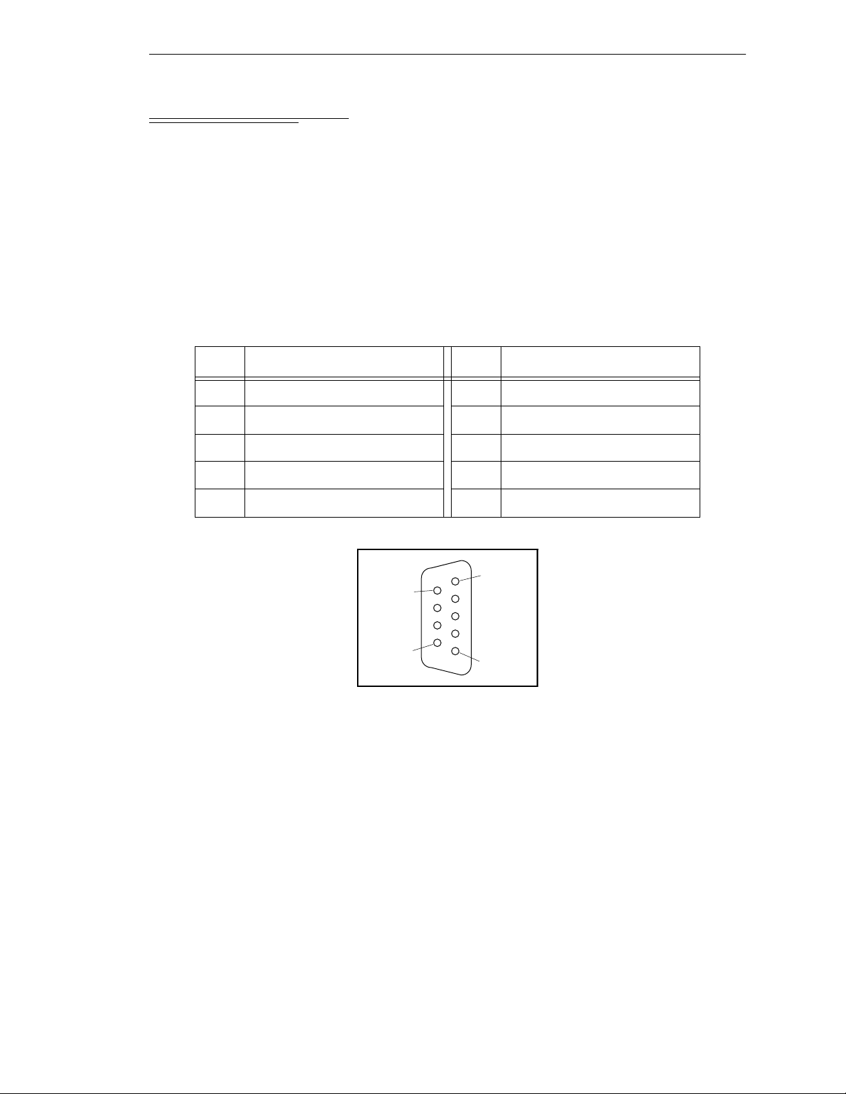
5.3 Serial I/O Connections, 030 Module
RS-422/485 Connector (on 030 Module)
The RS-422/485 connector is a DE-9F 9-pin female connector. The pin assignments and
locations are shown below. RS-422 is a point-to-point protocol for connection to a single
destination. This por t can also be configured as a “multi-dr op” port (RS-485).
Serial I/O Connections, 030 Module
To change the configuration use the
instruction. This port is designated
Table 5-1. RS-422/485 Conn e c to r Pin As sig n ment s
CONFIG_C
LOCAL.SERIAL:1
utility program or the V+
.
Pin Signal Pin Signal
1RTS+ 6RTS–
2RXD+ 7RXD–
3TXD+ 8TXD–
4CTS+ 9CTS–
5Ground
Pin 5
Pin 9
Pin 6
Pin 1
FSET
program
Figure 5-1. RS-422/485 Fema le Co n nector Pin Loca tio n s (on 03 0 m odule)
Adept MV Controller User’s Guide, Rev C 61
Page 84
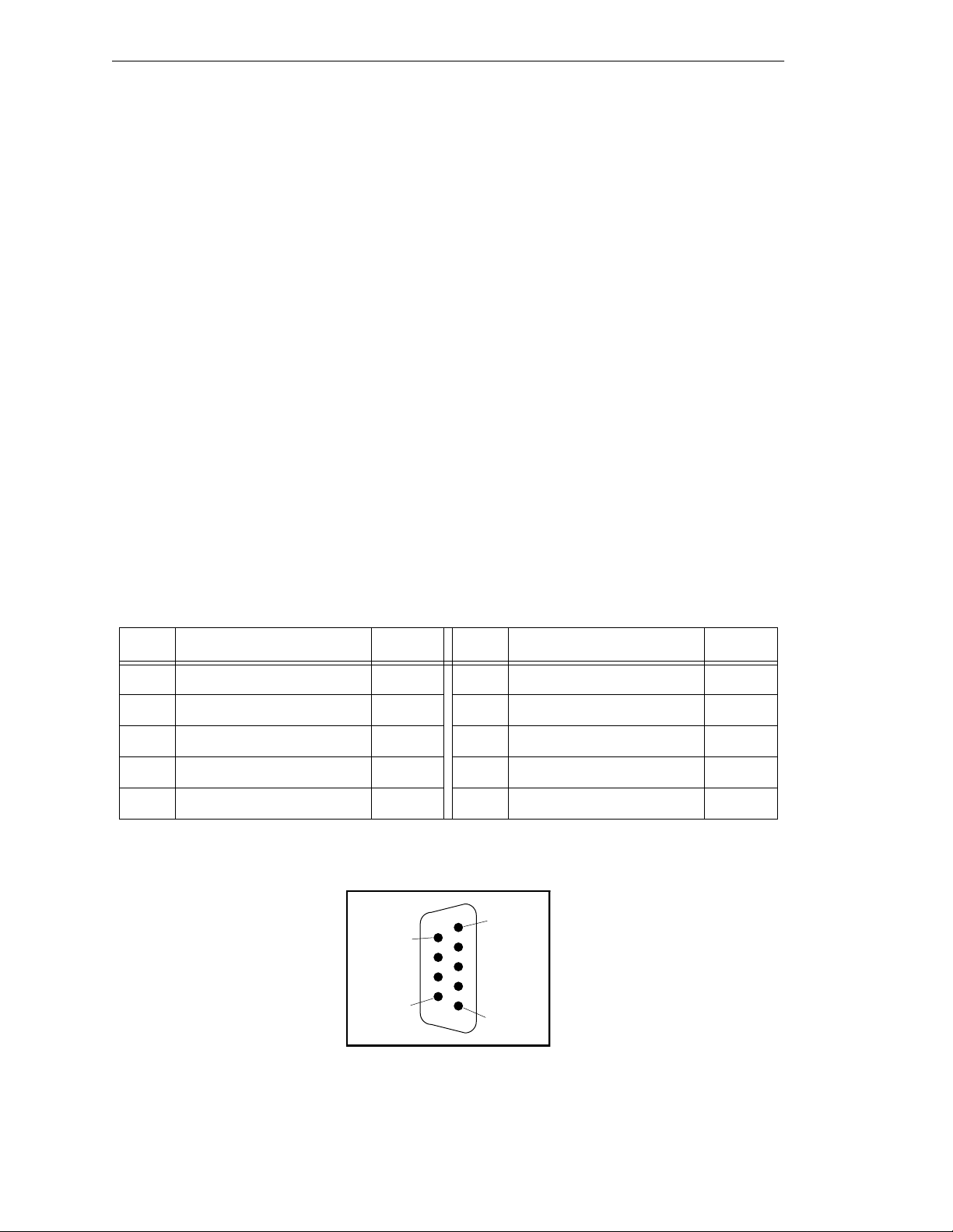
Chapter 5 - 030 Processor Module
RS-232/Term Connector (on 030 Module)
The RS-232/Term connector is a DE-9P 9-pin male connector that is pin-compatible with
the serial connector for AT compatible computers. The pin assignments and locations are
shown b e l o w.
The port supports DTR, DSR, RTS, and CTS si gna ls, used for “hardware handshake”, also
known as “modem control”. By default, these signals are not enabled. To configure the
port speed and other communicati ons par amet ers , us e the
+
V
LOCAL.SERIAL:2
Used in an S-Series System
If the controller is an S-Series model, then the customer-supplied ASCII or ANSI terminal
plugs into this connector on the main system processor; see Table 5-3 and the terminal
installation information in section 3.9. If you have more than one processor module, the
terminal is always connected to the mai n system module ( in slot 1).
Used in an A-Series System
If the controller is an A-Series model, then this connector can be used for general serial
communic ation. However, you can redirect the monitor ou tp u t of an A-Series system to
this connector on the 030 module using a DIP switch on the SIO module; see section 7.2
for information on that switch.
program instruction or the
FSET
.
FSET
CONFIG_C
utility program, the
monitor command. This port is designated
Table 5-2. RS-232/Term Connector Pin Assignments
Pin Signal Type Pin Signal Type
1not used 6DSR (DCE Ready) Input
2 RXD (From Device) Input 7 RTS (Request to Send) Output
3 TXD (To Device) Output 8 CTS (Clear to Send) Input
4 DTR (DTE Ready) Output 9 not used
5 SG (Signal Ground)
Pin 1
Pin 6
Pin 9
Pin 5
Figure 5-2. RS-232/Term Male Connector Pin Locations (on 030 module)
62 Adept MV Controller User’s Guide, Rev C
Page 85

Serial I/O Connections, 030 Module
Typical Cable Connections
For many applications, including connecting to a serial printer or terminal, 25-pin or 9-pin
adapter cables may be required. The next few tables give some examples. Because the
Adept MV controller uses the same connector and co m patible p inouts as the IBM PC -AT
computer, suitable cables may be available from your local compu ter dealer.
• Table 5-3, “Pin Assignments for 9-Pin to 25-Pin (DCE) Cable”
• Table 5-4, “Pin Assignments for 9-Pin to 25-Pin (DTE) Cable”
• Table 5-5, “Pin Assignments for 9-pin to 25-pin (Wyse WY-60 Terminal) Cable”
• Table 5-6, “Pin Assignments for 9-pin to 9-pin (AT-Compatible) Cable”
• Ta ble 5-7, “Typical 25-pin Null-Modem Adaptor Pinout”
Typical Cable Connections, 9-pin to 25-pin (DCE)
The following connections will work for many applications, including most modems and
other DCE (Data Circuit-terminating Equipment) devices. See next page for typical
connections to a terminal or other 25-pin DTE device.
Table 5-3. Pin Assignments for 9-Pin to 25-Pin (DCE) Cable
030 RS-232
9-Pin Female
Pin Number Function
25-Pin Male
(DCE)
Pin Numb er
not used Shiel d 1
1 (CD c a rrier detect - not use d)
a
8
2 RXD (f rom DCE device) 3
3TXD (to DCE device) 2
4DTR
b
(to DCE device ) 20
5Signal ground 7
6DSR
7RTS
8CTS
9 (RI rin g indicator - not used)
a
Pins 1 and 9 are not connected ins ide th e Adept MV Controller.
b
(from DCE device) 6
b
(to DCE device) 4
b
(from DCE device) 5
a
22
No connection is required, but if you are using a standard cable
that connects to these pins no damage should occur.
b
Pins 4, 6, 7, and 8 are used for “hardware handshake”, also
known as “modem control”. To enable them, use the
+
utility program, the V
program instruction, or the
FSET
CONFIG_C
FSET
monitor command. In some applic a tions you can omit some or
all of these li ne s; cons u l t the doc ume ntat ion for the de vice tha t
you are connecting to the Adept controller.
Adept MV Controller User’s Guide, Rev C 63
Page 86
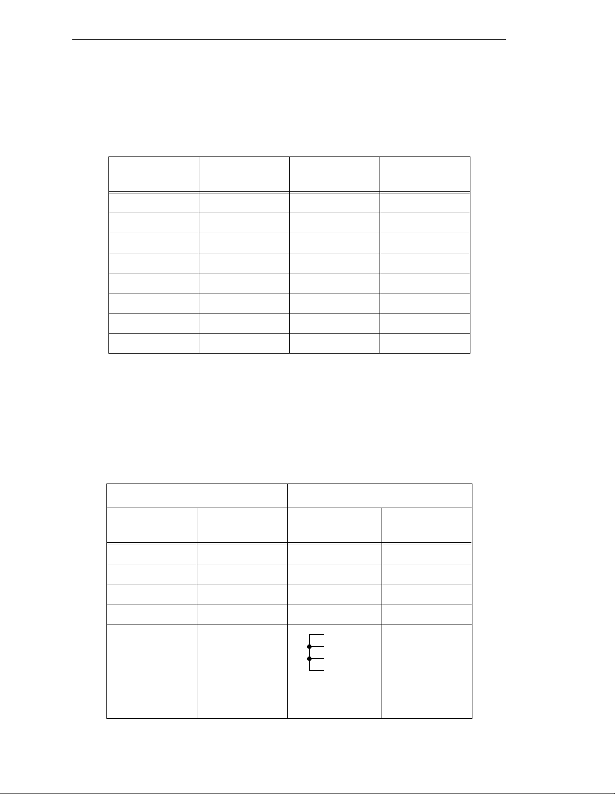
Chapter 5 - 030 Processor Module
Typical Cable Connections, 9-pin to 25-pin (DTE)
Most termi nals and some compute rs use DTE (Data Terminal Equipment) pinouts.
Remember to en able “m odem cont rol ” ( u sing
RTS, or CTS signals.
Table 5-4. Pin Assignment s for 9-Pin to 25- Pin ( DTE ) Ca ble
CONFIG_C
) if you are us ing the DTR, DSR,
9-Pin Female
Pin Number Function
25-Pin DTE
Pin Num ber Function
— not used 1 Shield
2RXD 2TXD
3TXD 3RXD
4 DTR 6 and 8 DSR and CD
5 Signal ground 7 Signal ground
6 DSR 20 DTR
7RTS 5CTR
8CTS 4RTS
Recommended Connections, 9-pin to 25-pin (Wyse WY-60 Terminal)
Adept recommends the use of a Wyse WY-60 terminal on S-Series Adept MV controllers.
The previous table show s a full “7-wire” DTE inter face with hardware hand shaki ng (f l ow
control). The following simplified connections will work with most terminals using DTE
pinouts, such as the Wyse WY-60 terminal. The WY-60 has a female 25-pin connector. This
“3-wire ” in t e rfa ce u se s so f tw a re fl ow co n t rol (X O N a nd X OF F control charact e rs ) .
Table 5-5. Pin Assignments for 9-pin to 25-pin (Wyse WY-60 Terminal) Cable
030 RS-232 Wyse WY-60 Terminal
9-Pin Female
Pin Number Function
25-Pin Male
Pin Number Function
— not used 1 Shield
2 RXD 2 TXD
3 TXD 3 RXD
5 Signal ground 7 Signal ground
4
5
6
20
(Pins 4, 5, 6, & 20
linked together)
64 Adept MV Controller User’s Guide, Rev C
RTS
CTS
DSR
DTR
Page 87
Serial I/O Connections, 030 Module
Typical Cable Connections, 9-pin to 9-pin (AT-Compatible)
The 030 module uses AT-compatible pinouts. Therefore, to connect it to another
AT-compatible 9-pin device, the following connections ar e required to swap over signals
as required. Remember to enable “modem control” (using
CONFIG_C
) if you are using the
DTR, DSR, RTS, or CTS sign als.
Table 5-6. Pin Assignments for 9-pin to 9-pin (AT-Compatible) Cable
030 RS-232 AT-Compatible
9-Pin Female
Pin Number Function
9-Pin Female
Pin Num ber Function
2RXD 3TXD
3TXD 2RXD
4DTR
a
6 and 1 DSR and CD
5 Signal ground 5 Signal ground
6 and 1
b
7RTS
8CTS
a
Pins 4, 6, 7, and 8 are used for “hardware handshake”, also known as
a
DSR
a
a
7RTS
4DTR
8CTR
“modem control”. In some applications you can omit some or all of these
lines; co nsu lt th e docu m entat io n fo r t he dev ice that y ou ar e con nect i ng t o the
Adept controller.
b
Pin 1 is not co nnected inside the Adept MV Cont roller. No connection is
required, but if y ou are using a stan dard cable that connects to th is pin no
damage should occur.
Adept MV Controller User’s Guide, Rev C 65
Page 88
Chapter 5 - 030 Processor Module
DTE, DCE, or AT-style?
There are two ways to make an RS-232 connection: detailed research and full
understanding; or a try-it-and-see method. In general, you will do no harm if you make an
incorrect connection between two genuine RS-232 ports. Try either of the connection types
described above (DTE or DCE) and see which works. If neither works, either the other
device has a non-standard pinout, or the devices are incorrectly configured (for example,
different speeds or different handshake methods).
The following information may assist if you want to attempt the research method.
Otherw ise, we rec ommend you skip the res t of this sub-section.
The RS-232C standard (and its successors, EIA-232-D and ANSI/EIA/TIA-232-E) define
two types of apparatus:
• DTE: Data Terminal Equipment
• DCE: Data Circuit-terminating Equipment (used to be known as "Data
Communications Equip ment.")
Modems are supposed to be DCE devices. Terminals are supposed to be DTE. Both are
supposed to use 25-pin D-Sub connectors. The standard only defines the connector and
pinout at the “point of demarcation”, which is to be no more than 3 meters from the DCE
device. Computers and prin te rs are not exp licitly addressed by the standard. In practice,
they often have a DTE-type pinout. Some have a DCE pinout. Increasingly, many
computer devices use an IBM PC-AT style 9-pin connector, which is strictly neither DTE
nor DCE.
The standard assumes th at you have two de vices, one DT E, the other DCE. If you need to
connect two DTE devices, the standard assumed that you would use a pair of modems or
other DCE devic es. To directly co nnec t two DTE dev ice s, y ou need to use a null mode m to
make the necessary connections. A null modem is an adaptor connector (or cable) that has
DCE pinouts at each end. Null modems are readily available at most computer stores. If
you need to build your own null modem, the table below shows the typical pinouts.
Table 5-7. Typical 25-pin Null-M od em Adap to r Pinout
25-Pin D (male) 25-Pin D (female) 25-Pin D (male) 25-Pin D (female)
1 Shield 1 Shield 5 CTS 4 RTS
2TXD 3RXD 6 & 8 DSR & CD 20 DTR
3RXD 2TXD 20DTR 6 and 8 DSR & CD
4 RTS 5 CTS 7 Ground 7 Ground
66 Adept MV Controller User’s Guide, Rev C
Page 89
5.4 Memory
The 030 system processor can be ordered with 2, 4, or 8 MB of DRAM. Co ntact Adept
Customer Service for infor matio n regarding memory upgr ade opt ions for 2 MB and 4 MB
processors.
5.5 VMEb us Add re ss
Each processor module in an Adept MV controller must have a unique module address.
The address is set on switch SW2 on the 030 PC board. Table 5-8 shows the switc h settings
for multiple processor modules. See Figure 5-3 for the location of SW2.
If you are using both 040 and 030 processor modules, each module must have a unique
address. You cannot set an 040 and an 030 to the same address. For example, if you have
an 040 and an 030 insta lled, one of them must be set a s module #1 and the ot her as module
#2. See section 5.7 for additional information.
Memory
Table 5- 8. Address Settings for the 030 Proces sor Module
SW2 Switch Position
a
Module
Number
1 (main proc) Off on on on on on on on
2 (auxiliary)OffonononononOffon
3 (auxiliary)OffononononOffonon
4 (auxiliary)OffononononOffOffon
a
The position notation on DIP switches can vary. If the switch is mar ked
open/closed, then open = off and closed = on.
12345678
Adept MV Controller User’s Guide, Rev C 67
Page 90

Chapter 5 - 030 Processor Module
5.6 030 Ju m per Settings
There are tw o jumpers on the 030 module that must be set correctly, depending on if it is
used as the main processor or an auxiliary processor. See the table below and Figure 5-3.
T able 5-9. Jumper Settings for 030 Processor Module
Processor Type Jumper Setting
030 #1 used as main processor SCON (JP1) = ON
SCLK (JP3) = ON
a
030 #2-4, used as auxiliary
processor
a
SCLK (JP3) jumper is ON for the main processor when used
SCON (JP1) = OFF
SCLK (JP3) = OFF
with newer SIO modules – 30330-12350, 30330-11351,
30332-12350, or 303 32-12 351. A ll SI O modules manufac tured
after 1994 req u ire JP3. It must be OFF when used with older
SIO modules – 30330-0030 1 or 30330-10351.
ON
1 2 3 4 5 6 7 8
SW2
SCON
JP1
SCLK
JP3
Adept 030 Board – Component Side
Figure 5-3. Switch and Jumper Locations on the 030 Module
68 Adept MV Controller User’s Guide, Rev C
Page 91
5.7 Use as an Auxiliary Processor
Additional 030 System processor modules can be installed in an Adept MV controller and
used as auxiliary processors to handle specific functions in an Adept automation system.
For example, you can have an auxiliary 030 ded icat ed to handling p rocessing for the
motion or vision portio n of a system, while th e main 030 handles the V
proce ssi ng. Th e
CONFIG_C
software ar e handled by each processor. See the V
utility program is used to specify which portions of the system
+
Release Notes for more information on
multiple processor systems. See Table 5-8 and Table 5-9 for switch and jumper setti ngs
required for auxiliary processors.
The serial ports on an auxiliary processor cannot be acce ssed by V
the main processor (processor #1).
5.8 030 Processor Module Specifications
Use as an Auxiliary Processor
+
system
+
programs running on
Table 5-10. 030 Technical Specifications
a
Processor 68030 @ 40 MHz
Math Coprocessor 68882 @ 32 MHz
Dynamic RAM 2, 4, or 8 Mb
Serial Ports one RS-232, at 300 – 38,400 bps
one RS 422/485, at 300 – 38,400 bps
Electrical Power Consumption 5 VDC (+0.25V/–0.15 V) at 3.0 A max
+12 VDC (± 2 V) at 10 mA
–12 VDC (± 2 V) at 10 mA
Width Occupies one backplane slot
a
Specifications subject to change.
Adept MV Controller User’s Guide, Rev C 69
Page 92

Page 93

040 Processor Module 6
6.1 Introduction
6.2 Connections and Indicators
6.3 Serial I/O Connections, 040 Mo dule
RS-422 Connector (on 040 Module)
RS-232/Term Connector (on 040 Module)
6.4 Memory
6.5 VMEbus Address
6.6 040 Jumper Settings
6.7 Use as an Auxiliary Pro ce ssor
6.8 040 Processo r Mod u l e Specifi cations
. . . . . . . . . . . . . . . . . . . . . . . . . . . . . .
. . . . . . . . . . . . . . . . . . . . . .
Used in an S-Series System
Used in an A-Series System
Connections from 040 RS-232 to Wyse Terminal
. . . . . . . . . . . . . . . . . . . . . . . . . . . . . . . .
. . . . . . . . . . . . . . . . . . . . . . . . . . . .
. . . . . . . . . . . . . . . . . . . . . . . . . .
. . . . . . . . . . . . . . . . . . . . . .
. . . . . . . . . . . . . . . . . . .
. . . . . . . . . . . . . . . . .
. . . . . . . . . . . . . .
. . . . . . . . . . . . . . . . . .
. . . . . . . . . . . . . . . . . .
. . . . . . . .
. . . . . . . . . . . . . . . . . .
72
72
73
73
74
74
74
76
76
77
77
79
79
Adept MV Controller User’s Guide, Rev C 71
Page 94

Chapter 6 - 040 Processor Module
6.1 Introduction
All Adept MV controllers require at least one system processor module; the module can
be an 030 or an 040. You can have bot h 030 and 040 modules i nstalled, up to a maximum
of 4 modules. The 040 is a single-slot 6U VM E module that can serve as a main or an
auxiliary system processor for an Adept MV controller. The CPU for this module is a
Motorola 68040 microprocess or run nin g at 25MHz. The mo dule c an be ord ered with 4 o r 8
MB of DRAM (not field upgradeable).
The 040 has two serial I/O connectors on the front of the module: one is an RS-232 port
and the other is an RS-422 port. In an S-Series Adept MV controller, the programmer’s
terminal connects through the RS-232 port on the primar y 040 module. (In an A-Series
controller , the monitor and keyboard normally connect to the Adept VGB module.)
The 040 can be used either as the main system processor, or as an auxiliary processor in
Adept MV controller systems; see section 6.7.
6.2 Connections and Indicators
➊
➋
➌
➍
➎
SF
A
B
D
R
S
4
2
2
R
S
2
3
2
/
T
E
R
M
040
#1
#2
ABORT
RESET
➊
Status LED’s. When lit:
SF indicat e s th e V MEbus
SYSFAIL
signal is being asserted by
the 040 module. Th is indi cat es one of the followin g
STP
SCR
C
VME
conditions:
• the system is being booted from disk, and V
completed its initialization.
+
has not yet
• the system watchdog timer has timed out.
• another module has issued a
SYSFAIL
signal.
STP indicates the 68040 processor has stopped executing
instructions.
A and VME – these vary in intensity during norma l
opera ti o n o f the syst e m.
SCR ind ica tes the modul e is c o nf i g ur e d to be the syste m
controller (main processor). Otherwise, this LED is off.
B and D are always off.
C is normally on (but off is OK).
➋
Abort switch – stops execu tion of the software running on
this CP U. Thi s b u tt o n is pre s se d only du ring system te s t s.
➌
Reset swit ch – sends a VMEbus reset signal is to all modules
on the backplane.
➍
RS-422 connector – for ge neral serial communi cation.
➎
RS-232/Term connector – terminal connec tion w ith an
S-Seri es co n t rolle r; can be us e d for serial co mmuni ca t io n
with an A-Ser ies model. See pag e74 for more information on
this connector when used with an A-Series model.
72 Adept MV Controller User’s Guide, Rev C
Page 95

6.3 Serial I/O Connections, 040 Module
RS-422 Connector (on 040 Module)
The RS-422 connector (upper conne ctor on front of module) is a DB-25F, 25-pin female
connector. The pin assi g nments and locations are shown below. RS-422 is a point-to-point
protocol for connection to a single destination. Thi s port cann ot be used for multi -drop
connections. (Whereas, the 030 module has a dual-mode RS-422/RS-485 port. )
Serial I/O Connections, 040 Module
To change the configuration use the
instruction. This port is designated
Table 6-1. RS-422 Connector Pin Assignments (on 040 Module)
CONFIG_C
LOCAL.SERIAL:1
utility program or the V+
.
Pin Signal Pin Signal Pin Locations
1NC 14
a
2
3
4RTS+ 17NC
5 CTS+ 18 RTS–
6DSR+ 19NC
7 Signal
8NC 21NC
9NC 22DSR
10 NC 23 DTR–
TXD+ 15 NC
b
RXD+ 16
20 DTR+
ground
a
TXD–
b
RXD–
Pin 25
Pin 14
FSET
Pin 13
Pin 1
program
11 NC 24 NC
12 NC 25 NC
13 CTS–
NC = do not connec t
a
Depending on what type of device you are connecting to, you may have to reverse the polarity
of the TXD signals.
b
Depending on what type of device you are connecting to, you may have to reverse the polarity
of the RXD signals.
CAUTION:
!
female c onnec tors. B e sure to la bel e ach conn ector an d take pr eca uti ons t o
avoid connecting to the wrong port.
The RS-422 and RS-232 ports on the 040 both use 25-pin
Figure 6-1. RS-422 Conne c to r on 040
Module
(25-Pin Female DB-25F,
upper connector)
Adept MV Controller User’s Guide, Rev C 73
Page 96
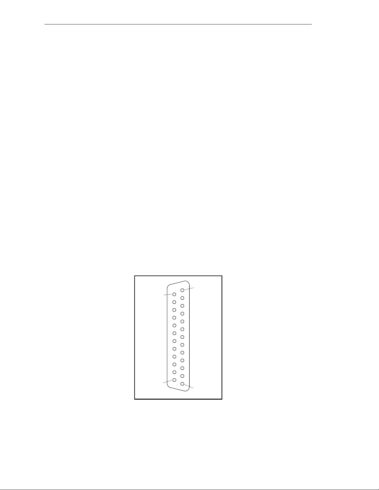
Chapter 6 - 040 Processor Module
RS-232/Term Connector (on 040 Module)
The RS-232/Term connector (lower connector on front of module) is a DB-25F, 25-pin
female connector. The pin assignments and locations are shown in Figure 6-2 and
Table 6-2. Th e co nn ector is conf igured as a DC E de v i ce (D a ta Circu it - te r minating
Equipment). If y ou ar e connecti ng to a device, such as a ter minal, c onfig ured as DT E (Data
Terminal Equipment), you should connect directly (pin 2 to pin 2, pin 3 to pin 3, etc.) If
you are connecting to another DCE device, you will need to cross over signals as
appropriate with a null modem (see page 66).
The port supports DTR, RTS and CTS signals, used for “hardware handshake”, also
known as “modem control”. By default, these signals are not enabled. To configure the
port speed and other communicati ons par amet ers , us e the
+
V
LOCAL.SERIAL:2
Used in an S-Series System
If the controller is an S-Series model, then the customer-suppl ie d ASCII terminal plugs
into this connector on the main system processor; see Tab le 6-3 and the te rminal
installation inf ormation in Sect ion 4.9 on page 54 . If you have more than one processor
module, the terminal is always connected to the main processor.
program instruction or the
FSET
.
FSET
CONFIG_C
utility program, the
monitor command. This port is designated
Used in an A-Series System
If the controller is an A-Series model, then this connector can be used for general serial
communic ation. However, you can redirect the monitor ou tp u t of an A-Series system to
this conn e ctor on the primar y 040 module using a DIP swit ch on the SIO module; see
sectio n 7.2 for informat ion on that switch.
Pin 13
Pin 25
Pin 14
Pin 1
Figure 6-2. RS-232 Connector on 040 Module
(25-Pin Female DB-25F, lower connector)
74 Adept MV Controller User’s Guide, Rev C
Page 97
Serial I/O Connections, 040 Module
Table 6-2. RS-232/Term Connector Pin Assignments (on 040 Module)
Pin Type Adept Signal Remote Signal
1Shield
2 input RXD TXD (Transmitted Data)
3 output TXD RXD (Received Data)
4inputCTS
a
RTS (Request to Send)
5output
RTS
a
CTS (Clear to Send)
6 output (always on) DSR (DCE Ready)
7 Signal gro und
8output
DTR
a
DCD (Data Carrier Detect)
15 output Reserve d (do not connect)
17 output Reserve d (do not connect)
b
20
input DCD (not used) DTR (DTE Ready)
24 input Reserved (do not connect)
a
Pins 4, 5 and 8 are used for “hardware handshake”, als o known as “modem
control”. By default, they are disabled. To enable them, use the
utilit y program, the V
+
program instruction, or the
FSET
FSET
CONFIG_C
monit or
command. In some applic ations you can omit some or all of these lines ;
consult the documentation for the d e vice that y o u are connecting to the Adep t
controller .
b
You may connect to p in 20, but V+ ignores this signal.
CAUTION: The RS-422 and RS-232 ports on the 040 both use 25-pin
female c onnec tors. B e sure to la bel e ach conn ector an d take pr eca uti ons t o
!
avoid connecting to the wrong port.
Adept MV Controller User’s Guide, Rev C 75
Page 98
Chapter 6 - 040 Processor Module
Connections from 04 0 RS-232 to Wyse Terminal
Adept recommends the use of a Wyse WY-60 terminal on S-Series Adept MV controllers.
The following connections will work with most terminals using DTE pinouts, such as the
Wyse WY-60 terminal. The WY-60 has a female 25-pin connector. This “3-wire” interface
uses sof tw a re fl o w co nt rol (XO N a nd X OF F control ch ar a ct e rs ) .
Table 6-3. Pin Assignmen t s for 25 -p in t o 25 -pin (Wyse WY-60 Terminal) Cab le
040 RS-232 Wyse Terminal
25-Pin Fem a le
Pin Number Function
1Shield 1Shield
2RXD2TXD
3 TXD 3 RXD
7 Signal ground 7 Signal ground
6.4 Memory
25-Pin Male
Pin Number Function
4
5
6
20
(Pins 4, 5, 6, & 20
linked together)
RTS
CTS
DSR
DTR
The 040 system processor can be ordered with eithe r 4 MB or 8 MB of DRAM. It is not
possible to u p grade a 4 MB module to an 8 MB module.
76 Adept MV Controller User’s Guide, Rev C
Page 99
6.5 VMEb us Add re ss
Each 040 module in an Adept MV controller must have a unique module address. The
address is set on Jumper block J22 on the 040 PC board (see Figure 6-3 for location of
jumpers). Table 6-4 shows the jumper settings fo r multiple p rocess or modules.
If you are using both 040 and 030 processor modules, each module must have a unique
address. You cannot set an 040 and an 030 to the same address. For example, if you have
an 040 and an 030 insta lled, one of them must be set a s module #1 and the ot her as module
#2. See section 6.7 for additional information.
Table 6-4 . Address Sett in gs for the 040 Proce sso r Module
VMEbus Address
Jumper Block J22 – Jumper Status
a
Module
Number
1 (main proc)InInInInOutInInIn
2 (auxiliary)OutInInInOutInInIn
3 (auxiliary) In Out In In Out In In In
4 (auxiliary) Out Out In In Out In In In
a
“In” means that the removable jumper is installed across the two indicated pins. “Out”
means the jumper is not installed.
1–2 3–4 5–6 7–8 9–10 11-12 13–14 15–16
6.6 040 Ju m per Settings
The table below shows the jumper settings for J1 a nd J20. See Figure 6-3 for the location of
the jumpers.
Table 6-5. Jumper Settings for 040 Processor Module
Jumper number Jumper Setting
J1 (SCON) In for main processor
(module #1)
Out for aux il iary processor
(module #2, 3, or 4)
J20 Standard setting is to install
jumpers acro ss pi ns 1 t o 3 and
pins 2 to 4.
Adept MV Controller User’s Guide, Rev C 77
Page 100
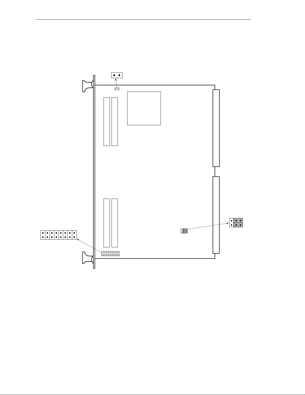
Chapter 6 - 040 Processor Module
J1
SCON
16
J22
1
2
Adept 040 Board – Component Side
Figure 6-3. Switch and Jumper Locations on the 040 Module
5
6
1
2
J20
78 Adept MV Controller User’s Guide, Rev C
 Loading...