

Page 1
GRouter4
Single Port 709.1 /852 LON/IP Router
User Guide
4.05
2007/06/06
Page 2

Copyright © 2007 by Adept Systems, Inc. All Rights Reserved.
Printed in USA.
Version 4.05, June 2007.
is document, the associated soware, and the associated online documentation are the
property of Adept Systems, Inc. and are loaned to the user under the terms of the End User
License Agreement. No title to or ownership of the soware described in this document or any of
its parts is transferred to customers. No part of this document may be reproduced or transmitted
in any form or by any means without the express written permission of Adept Systems, Inc.
Unauthorized copying or use of the soware or any associated materials is contrary to the
property rights of Adept Systems, Inc. and is a violation of state and federal law. is material
must be returned to Adept Systems upon demand.
Disclaimer:
Adept Systems makes no representations or warranties regarding the contents of this document.
Information in this document is subject to change without notice and does not represent a
commitment on the part of Adept Systems, Inc.
Trademarks:
GadgetStack and the Adept Systems Logo are registered trademarks of Adept Systems, Inc.
GRouter, GRouter4, GR4, GRouter3, GR3, GNode, GNode3, GN3, GRN3, GadgetNode,
GadgetNIC, and GadgetTek are trademarks of Adept Systems, Inc.
All other product and company names are trademarks or registered trademarks of their respective
holders.
Contact Information:
Adept Systems Incorporated
2966 Fort Hill Road
Eagle Mountain, Utah 84005-4108 USA
Voice: 801.766.3527
Fax: 801.766.3528
Web: www.adeptsystemsinc.com
Email: info@adeptsystemsinc.com
-2-
Page 3

Table of Contents
1. Overview ...................................................................................................7
1.1. Introduction ...........................................................................................7
1.2. Conguration Parameters .....................................................................9
1.3. Modes of Operation ............................................................................10
1.3.1. Manual Mode..................................................................................10
1.3.2. Normal Mode .................................................................................10
1.4. Applications of the GRouter Device....................................................10
1.4.1. Multi-site building automation networks.....................................10
1.4.2. IP backbones for LON trac aggregation....................................11
1.4.3. Roaming Connections ...................................................................12
1.5. IP Addressing Modes ...........................................................................12
1.6. 852 to 852 Bridging Router Mode .......................................................14
1.7. Redundant Twin Mode ........................................................................15
1.7.1. Denitions......................................................................................17
1.7.2. Status SNVT ...................................................................................17
1.7.3. Alarm SNVT...................................................................................18
1.7.4. Status Report UNVT......................................................................18
1.8. System Requirements...........................................................................20
1.8.1. System Requirements.....................................................................20
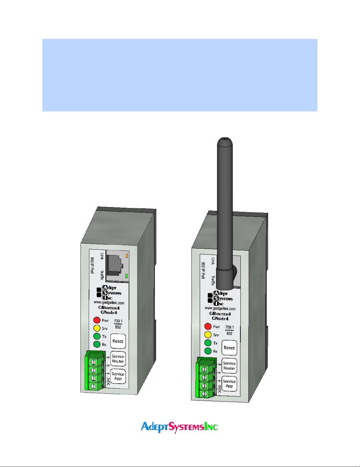
1.8.2. Button, Indicators, and Connectors for GRouter ........................21
1.8.3. Wiring.............................................................................................21
1.8.4. FTT-10 XCVR LonTalk Network Termination.............................22
2. Web Conguration..................................................................................24
2.1. Default IP Conguration.....................................................................24
2.1.1. Ethernet ..........................................................................................24
2.1.2. WiFi (802.11b)................................................................................25
2.1.3. Establishing Connection................................................................27
2.1.4. Restoring Factory Defaults ............................................................28
2.1.4.1. Basic Procedure........................................................................28
2.1.4.2. IP and WiFi settings.................................................................28
2.1.4.3. Web user name, password, and http port ...............................28
2.1.4.4. All parameters ..........................................................................28
2.1.5. WiFi Setup in Windows XP...........................................................29
2.2. Status Page ............................................................................................30
2.3. Router Setup .........................................................................................32
2.3.1. Normal Mode Router Setup...........................................................32
-3-
Page 4

2.3.2. Manual Mode Router Setup...........................................................36
2.3.3. Bridging Router Setup ...................................................................37
2.4. IP Setup Page........................................................................................40
2.5. WiFi Setup Page....................................................................................42
2.6. 709 Setup Page......................................................................................44
2.6.1. Node Parameters............................................................................44
2.6.2. Forwarding Tables..........................................................................45
2.7. Channel List Page.................................................................................47
2.7.1. Normal Mode Channel List Page ..................................................47
2.7.2. Manual Mode Channel List Page ..................................................48
2.8. Device Detail Page................................................................................50
2.9. Diagnostics Page...................................................................................52
2.10. DDNS Setup Page.................................................................................54
2.11. Twin Setup Page ...................................................................................55
2.12. Twin Mode Status Page ........................................................................58
2.13. Contacts Page .......................................................................................60
3. Network Integration and Management...................................................61
3.1. Manual Mode Example ........................................................................61
3.2. Normal Mode With i.LON Conguration Server Example...............61
3.3. Communicating With Lonmaker With IP Interface..........................62
3.4. Commissioning GRouter Device With LonMaker.............................63
3.5. NAT Router Example ...........................................................................65
3.6. DDNS Router Example ........................................................................66
3.7. Redundant Twin Mode Example.........................................................67
3.8. Conguring with the Coactive Router-LL..........................................71
3.8.1. Manual Mode..................................................................................71
3.8.2. Normal Mode With Router-LL Conguration Server .................72
4. Firmware Upgrade Instructions..............................................................73
-4-
Page 5

List Of Figures
Figure 1.1: Network Layers...................................................................................................8
Figure 1.2: Network Connector Types and Associated Layers ...........................................8
Figure 1.3: CN to IP Router/Gateway Architecture............................................................9
Figure 1.4: GRouter 3 Architecture......................................................................................9
Figure 1.5: Multi-site building automation network with internet connectivity ............11
Figure 1.6: Example Hybrid Network................................................................................11
Figure 1.7: Example WiFi Ad Hoc Network......................................................................12
Figure 1.8: Unicast ..............................................................................................................13
Figure 1.9: Mulitcast ...........................................................................................................13
Figure 1.10: 852 Bridging Router Architecture.................................................................14
Figure 1.11: Two redundant routers between the same channels ....................................15
Figure 1.12: Redundant Twin Mode Application..............................................................16
Figure 1.13: Front terminal block detail with standard connector..................................22
Figure 1.14: Front terminal block detail with optional pluggable connectors................22
Figure 1.15: Optional internal terminator disabled..........................................................23
Figure 1.16: Optional internal terminator set to Free Topology mode ...........................23
Figure 1.17: Optional internal terminator set to Bus mode.............................................23
Figure 2.1: Ethernet setup with hub or switch ..................................................................24
Figure 2.2: Ethernet with direct connect crossover cable.................................................25
Figure 2.3: WiFi setup with access point and Ethernet connection to host computer ...25
Figure 2.4: WiFi setup with ad hoc bridge and Ethernet connection to host computer.26
Figure 2.5: WiFi setup with ad hoc WiFi card on PC .......................................................26
Figure 2.6: WiFi setup with access point and WiFi card on PC .......................................26
Figure 2.7: User Name and Password Authentication ......................................................27
Figure 2.8: Status Page ........................................................................................................30
Figure 2.9: Router Setup Page ............................................................................................32
Figure 2.10: Reboot Page....................................................................................................36
Figure 2.11: Bridging Router Mode Setup Page................................................................38
Figure 2.12: IP Setup Page..................................................................................................40
Figure 2.13: 709 Setup Page Main Section.........................................................................44
Figure 2.14: Subnet Forwarding Table...............................................................................46
Figure 2.15: Group Forwarding Table ...............................................................................46
Figure 2.16: Channel List Page...........................................................................................47
Figure 2.17: Channel List Page in Manual Mode ..............................................................49
Figure 2.18: Device Detail Page .........................................................................................51
-5-
Page 6

Figure 2.19: Diagnostics Page ............................................................................................52
Figure 2.20: Dynamic DNS Conguration Page...............................................................54
Figure 2.21: Twin Mode Setup Page...................................................................................55
Figure 2.22: Twin Mode Status Page..................................................................................58
Figure 2.23: Contacts Page .................................................................................................60
Figure 3.1: Conguration Server Screen ...........................................................................62
Figure 3.2: Initial LonMaker Drawing...............................................................................64
Figure 3.3: Router Channel Setup......................................................................................64
Figure 3.4: Service Pin Dialog ............................................................................................65
Figure 3.5: Fully Commissioned Router............................................................................65
Figure 3.6: NAT LAN to WAN Architecture .....................................................................66
Figure 3.7: LonMaker New Device Dialog ........................................................................68
Figure 3.8: LonMaker New Device Channel Dialog .........................................................69
Figure 3.9: LonMaker Drawing With Commissioned Monitoring Device .....................69
Figure 3.10: New Virtual Functional Device Dialog.........................................................70
Figure 3.11: Functional Blocks NV Shapes Dialog ...........................................................70
Figure 3.12: Functional Block On Drawing ......................................................................71
-6-
Page 7

1. Overview
1.1. Introduction
e GRouter (GR4) router supports two open standard protocols, namely ANSI/EIA 709.1 and
ANSI/EIA 852. Both the ANSI/EIA 709.1 and ANSI/EIA 852 are dened by the Consumer
Electronics Association Technology & Standards R7.1 HCS1 Subcommittee. For more details see
http://ce.org/. For the sake of brevity the remainder of the document will refer to the
standards as 709.1 and 852. 709.1 is also known by its trademarked name, LonTalk®. A 709.1
network is also commonly referred to as a Local Operating Network or LON. is document will
use 709.1 network and LON interchangeably.
e 852 protocol acts as the transport service to convey 709.1 messages over Internet Protocol (IP)
networks. is technique of using another protocol (i.e. 852) to transport a message over an
alternate media is oen referred to as tunneling. In 852 parlance the tunneled protocol is a
Component Network (CN) protocol. e 852 protocol is a generic tunneling protocol and is not
limited to 709.1. However, a particular implementation of the 852 protocol may only support the
tunneling of a single CN protocol. e tunneled CN messages have no information or awareness
of the tunneling process. Although some of the gures in this document use CN or CN/IP to
represent a component network or component network to internet protocol connection, the only
CN currently supported by the GRouter device is 709.1
A component network protocol is oen called a eldbus due to its use for machine to machine
networking and control in the eld. is document, however, will only use the term component
network or CN.
852 not only provides the vehicle to transport ANSI 709.1 messages across IP, but it also provides
management of these connections or routes. A logical grouping of 852 devices that exchange
packets is called an 852 channel. One may think of an 852 channel as a kind of virtual LAN on an
IP network.
A GRouter device forwards 709.1 packets to or from an IP channel (using an Ethernet or WiFi
transceiver) and a CN channel (using twisted pair FT-10 or RS-485 transceivers). e GRouter
device has a presence on, or physical connection to, both channels. e router takes 709.1
messages from the component network, wraps them in an 852 packet and sends them over the IP
network. e GRouter device also receives 852 packets on its IP interface, unwraps them and puts
the 709.1 messages on the CN channel. e virtual 852 channel looks like a CN channel to CN
nodes. e IP element is transparent. is enables a at network and is more easily managed and
scaled than using CN to IP interfaces that do not hide the IP element from the CN nodes. e
important thing is not what the CN to IP device is called but how transparent it makes the IP
network appear to the CN nodes.
Network connection devices can operate at dierent layers of particular networks protocol stack.
709.1 is an OSI 7 Layer type protocol. Whereas the Internet Protocol has only 4 layers. (See Figure
Figure 2.1 for a diagram of the dierent layers of the two protocols.)
-7-
Page 8
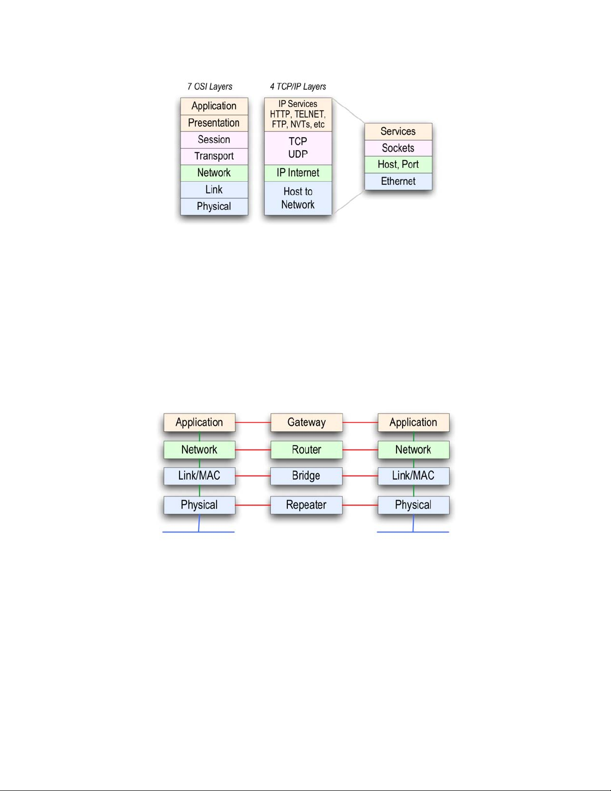
Fig.1.1: Network Layers
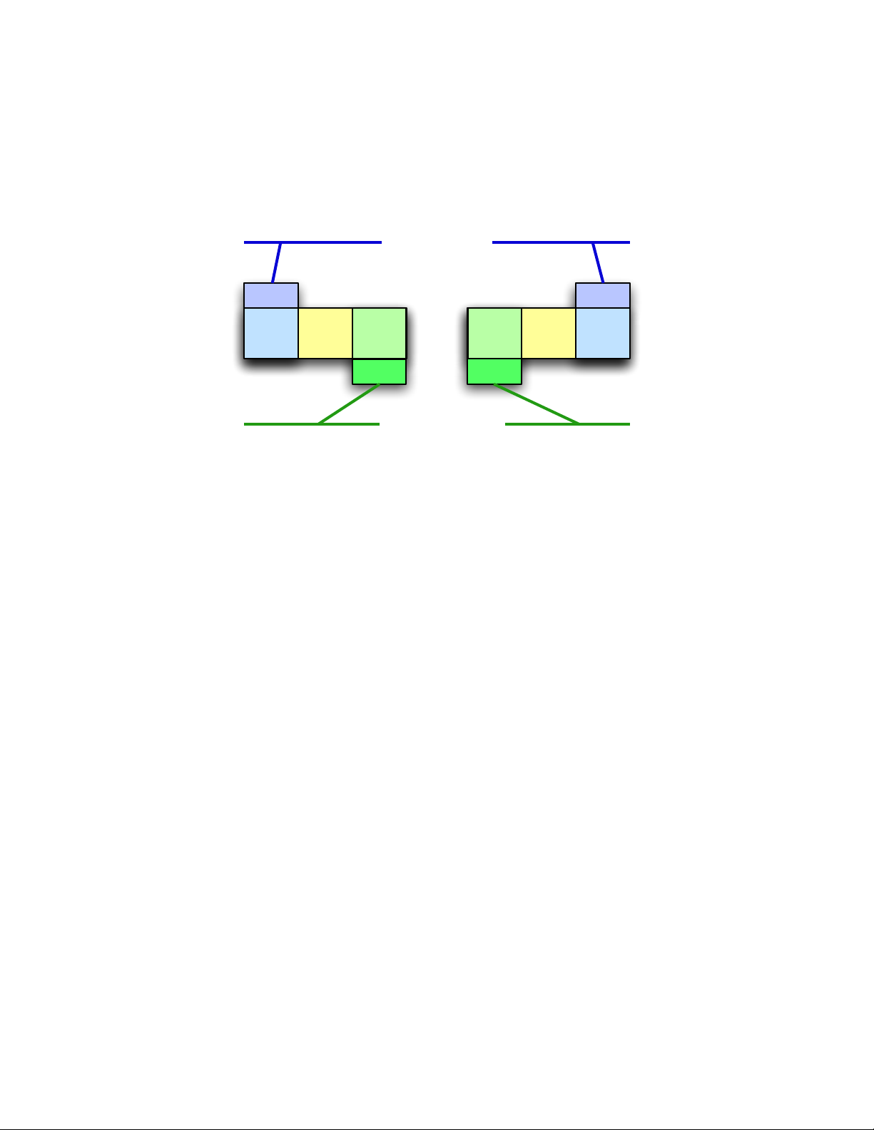
A network connector is a device that joins dierent parts of a network. Connectors have a specic
name that is dependent on the layer at which the connector operates. For example a router
operates at the network layer and a gateway at the application layer. Because higher layers of the
protocol do not have access to some of the information stripped away by lower layers, network
connectors operating at dierent layers have dierent capabilities. ere is also some abuse of
terminology so that the descriptions of network connectors from dierent manufacturers may be
confusing. For example, a repeating router may be called a repeater for short. Although a
repeating router acts similarly to a physical layer repeater, it operates at the network layer and is
not equivalent. It is usually best to nd out at which layer a network connector operates.
Fig.1.2: Network Connector Types and Associated Layers
e GRouter device is a more complex connector because is connects two dierent protocols and
also connects the protocols at dierent layers. On the IP side the GRouter device operates at the
application layer and so is appropriately called an IP Gateway. On the 709.1 side the GRouter
device operates at the network layer and is appropriately called a 709.1 router. So depending on
the user’s perspective the GRouter could be called a gateway or router or a router/gateway. (See
Figure 2.3)
-8-
Page 9
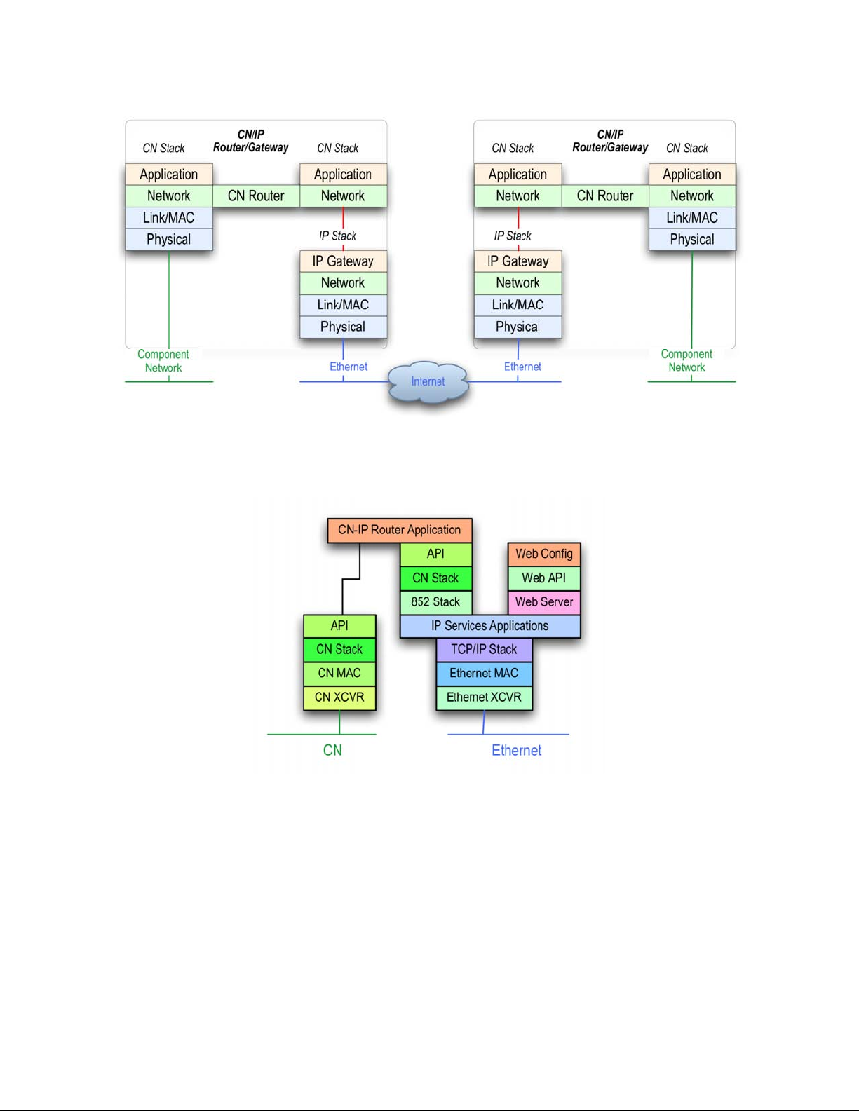
Fig.1.3: CN to IP Router/Gateway Architecture
e GRouter device also employs a web server for conguration purposes. (See Figure 2.4)
Fig.1.4: GRouter 3 Architecture
1.2. Conguration Parameters
e information required for successful ANSI/EIA 709.1 transport can be broken up into the
following two categories: device parameters and channel parameters.
Device parameters include information such as: IP address, IP port, Name, and Address of
conguration server.
A channel is a logical grouping of LON to IP routers. e minimum requirement for tunneling
ANSI/EIA 709.1 data is the use of two routers. Router A sends data to Router B and vise versa.
However, routers can also send data to more than one router. In such a case, Router A sends data
to Routers B, C, and D, which in turn send data back.
-9-
Page 10

A channel, then, is dened as a group of routers that all send information to each other. e lines
of communication are open in both directions and to all members—a complete mesh of
connections.
Typically, channels are managed through the use of a conguration server (called Normal mode
see below). e conguration server informs all members in the channel about the channel
information, which includes the adding and removing of channel members. Conguration
servers are capable of managing multiple channels, while routers belong to only one channel at a
time.
Lon to IP routers can also be managed manually by conguring each device uniquely (called
Manual mode, see below). In such a manual conguration, for proper operation, devices must
have mutual membership in each other’s channel lists. at is if Device A is in Device B’s channel
list then Device B must be in Device A’s channel list. However if Device C is in Device B’s channel
list, Device C does not have to be in Device A’s channel list.
1.3. Modes of Operation
e GRouter device can operate in one of two modes: (1) Manual, (2) Normal.
1.3.1. Manual Mode
In Manual mode the user has control over the GRouter device's conguration only. e user can
change the GRouter device's operating information and determine to whom the router will send
information. In Manual mode the GRouter device will honor read requests from other devices or
conguration servers, but it will block requests to write or change internal parameters. is is a
more secure mode and may be preferred on open networks. is mode is also preferable with
non-standard congurations such as Flood Mode or DDNS.
1.3.2. Normal Mode
Normal mode allows the user to view conguration data and channel data set by a remote
conguration server such as an i.LON® conguration server. e conguration server sets some
of the operating parameters of the GRouter device. Conguration servers mostly manage the
device's channel. e channel is made up of other devices to which the GRouter device will
tunnel or send ANSI/EIA 709.1 data. In Normal mode the adding and deleting of devices is
managed exclusively by the assigned conguration server. e conguration server provides a
single interface to add and delete devices. Finally, Normal mode permits read access to
information by other devices and write access to information for the assigned conguration
server.
Note: Echelon’s LNS based VNI interface (LonMaker) only works in Normal mode. In order for a
GRouter device to communicate directly over an IP channel to a VNI interface requires that the
GRouter device be in Normal mode.
1.4. Applications of the GRouter Device
1.4.1. Multi-site building automation networks
e interfaces described here provide the management necessary for the ANSI/EIA 852 to tunnel
ANSI/EIA 709.1 packets successfully over IP. is ability provides wide area network (WAN)
-10-
Page 11
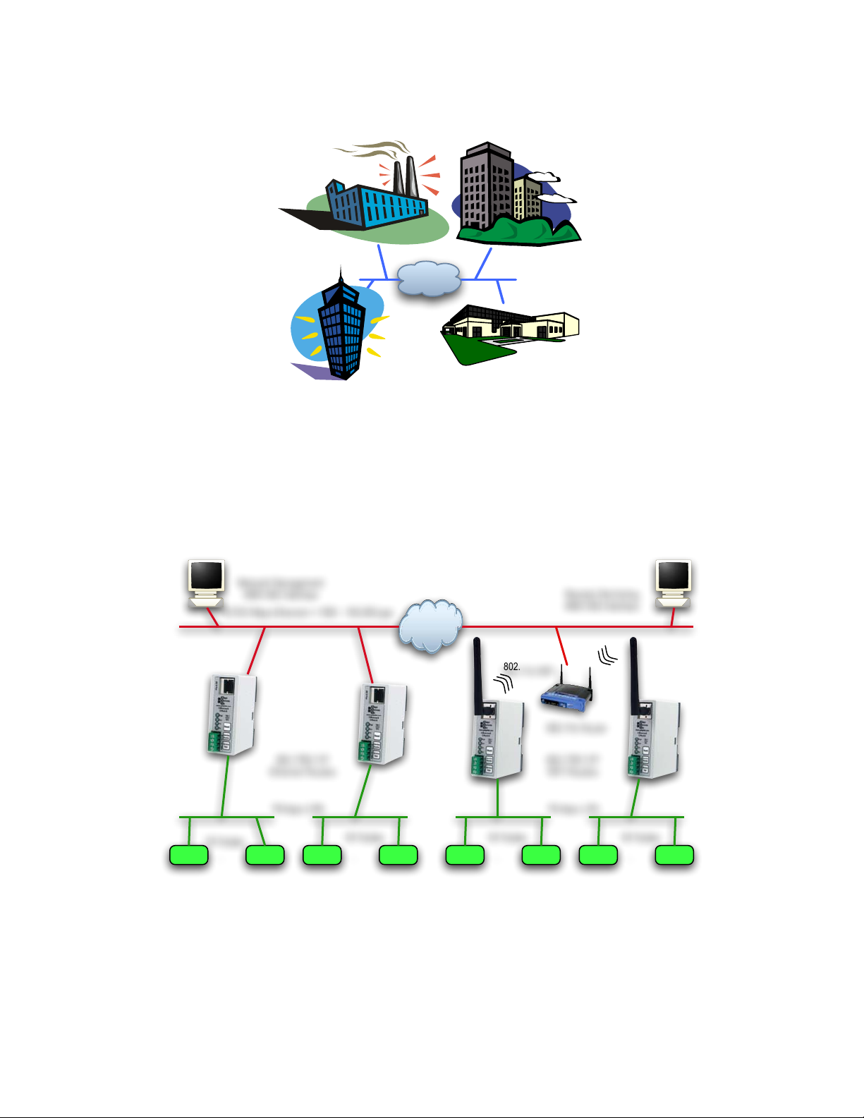
support to ANSI/EIA 709.1 networks. is allows multi-building or multi-site connection of
automation networks.
Internet
Fig.1.5: Multi-site building automation network with internet connectivity
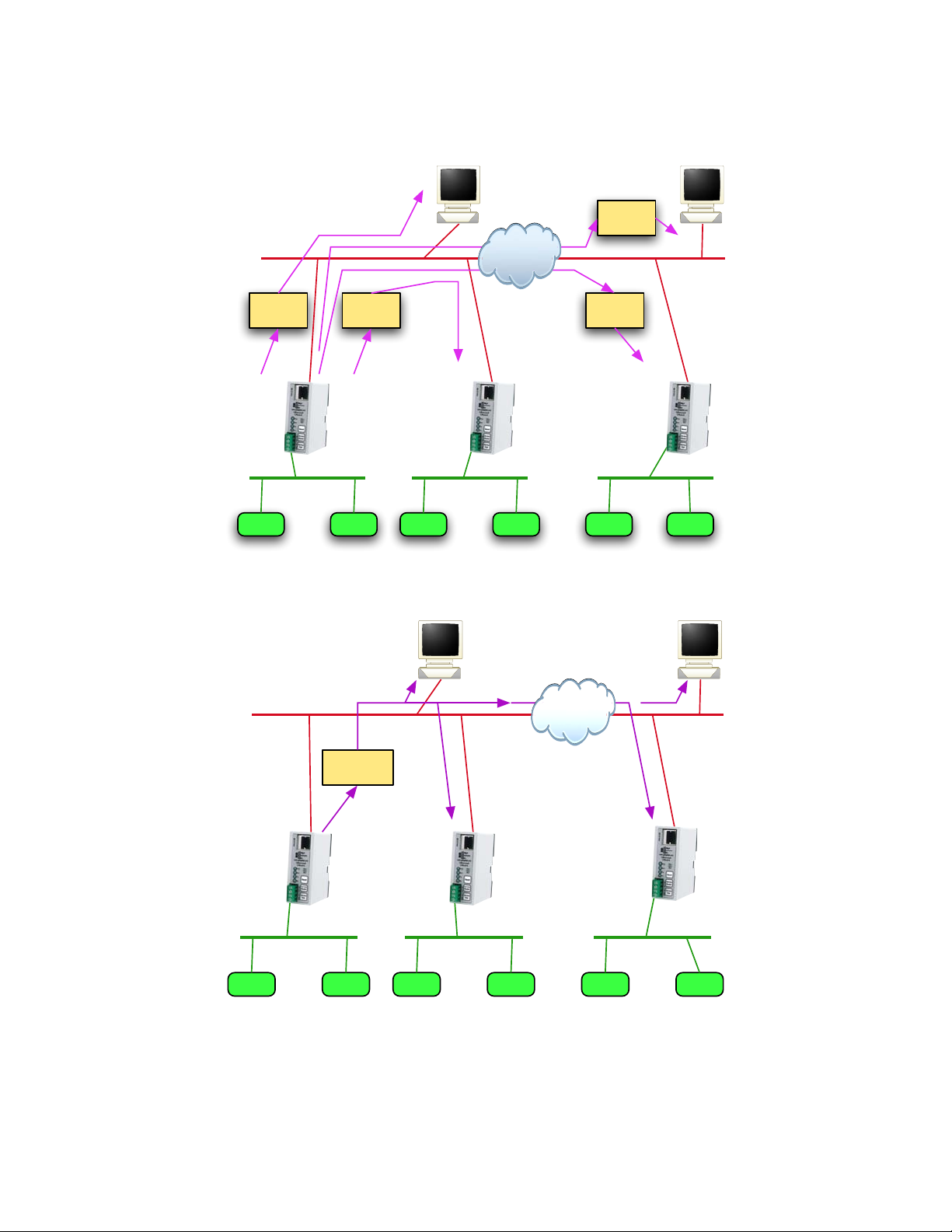
1.4.2. IP backbones for LON trac aggregation
Furthermore, since the IP networks can support much higher trac capacity, GRouter devices
can also be used to aggregate 709.1 trac from several LON channels over one IP channel. e
ability to aggregate larger trac volumes allows several GRouter devices and other 709.1 to IP
routers to be used as network backbones for 709.1 networks.
Node Node
...
Node Node
...
Node Node
...
Node Node
...
78 kbps LON 78 kbps LON
64 Nodes
64 Nodes 64 Nodes 64 Nodes
10/100 Mbps Ethernet ! 1000 - 100,000 pps
Network Management
ANSI 852 Interface
852 /709.1/IP
Ethernet Routers
Internet
852 /709.1/IP
WiFi Routers
Remote Monitoring
ANSI 852 Interface
802.11b Router
802.11b WiFi
Fig.1.6: Example Hybrid Network
-11-
Page 12
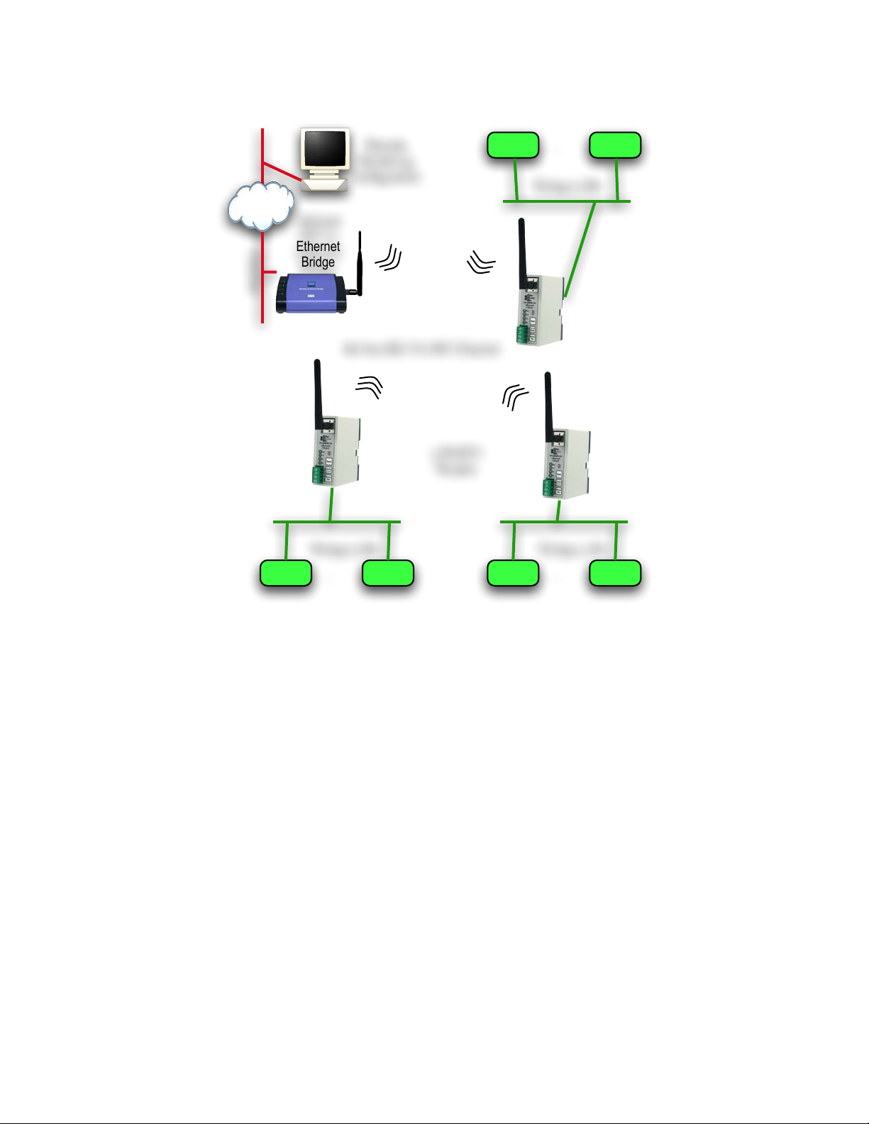
Node Node
...
Node Node
...
78 kbps LON 78 kbps LON
Ethernet
Remote
Monitoring
Configuration
LON/WiFi
Routers
Optional
WiFi to
Ethernet
Bridge
Ad Hoc 802.11b WiFi Channel
Node Node
...
78 kbps LON
Internet
Fig.1.7: Example WiFi Ad Hoc Network
1.4.3. Roaming Connections
Finally, LON to IP gateways may be connected to specialized IP applications instead of to other
gateways. Connecting an IP application to a GRouter device provides these specialized
applications with roaming capabilities which would be dicult if these applications were required
to be directly connected to the 709.1 network (e.g., GadgetAnalyzer, LonMaker-3, etc.). An
example of how several GRouter devices can be interconnected to support an IP backbone for
several LON networks is show in Figure 2.5.
1.5. IP Addressing Modes
e GRouter device uses one of two forms of IP addressing: unicast and multicast. Multicast
currently only works when in manual mode.
e advantage of multicast is that for networks with multiple Gateways (especially in ood
mode), multicast may be more ecient. e disadvantage of multicast is that some internet
routers do not support it. Multicast mode can reduce the IP trac relative to unicast when there
are a large number of 852 devices in the channel. Up to 255 devices per IP domain are supported
with multicast. Some older IP routers do not support multicast and therefore you will not be able
to route 852 packets across a unicast only router with multicast addressing. IP router support for
-12-
Page 13
Multicast is not a concern when all the 852 devices share the same subnet. e following gures
illustrate the dierences between multicast and unicast.
Node Node
...
Node Node
...
Node Node
...
IP Network
ANSI 852 709.1/IP
Gateway/Router
ANSI 852 709.1/IP
Gateway/Router
Unit-Cast
Packet
A
B
C
DE
Source
Unit-Cast
Packet
Unit-Cast
Packet
Unit-Cast
Packet
Destination
Destination
Destination
Destination
Internet
Fig.1.8: Unicast
Node Node
...
Node Node
...
Node Node
...
IP Network
ANSI 852 709.1/IP
Gateway/Router
ANSI 852 709.1/IP
Gateway/Router
Multi-Cast
Packet
A
B
C
DE
Source
Internet
Multiple Destinations
Multiple Destinations
Fig.1.9: Mulitcast
-13-
Page 14
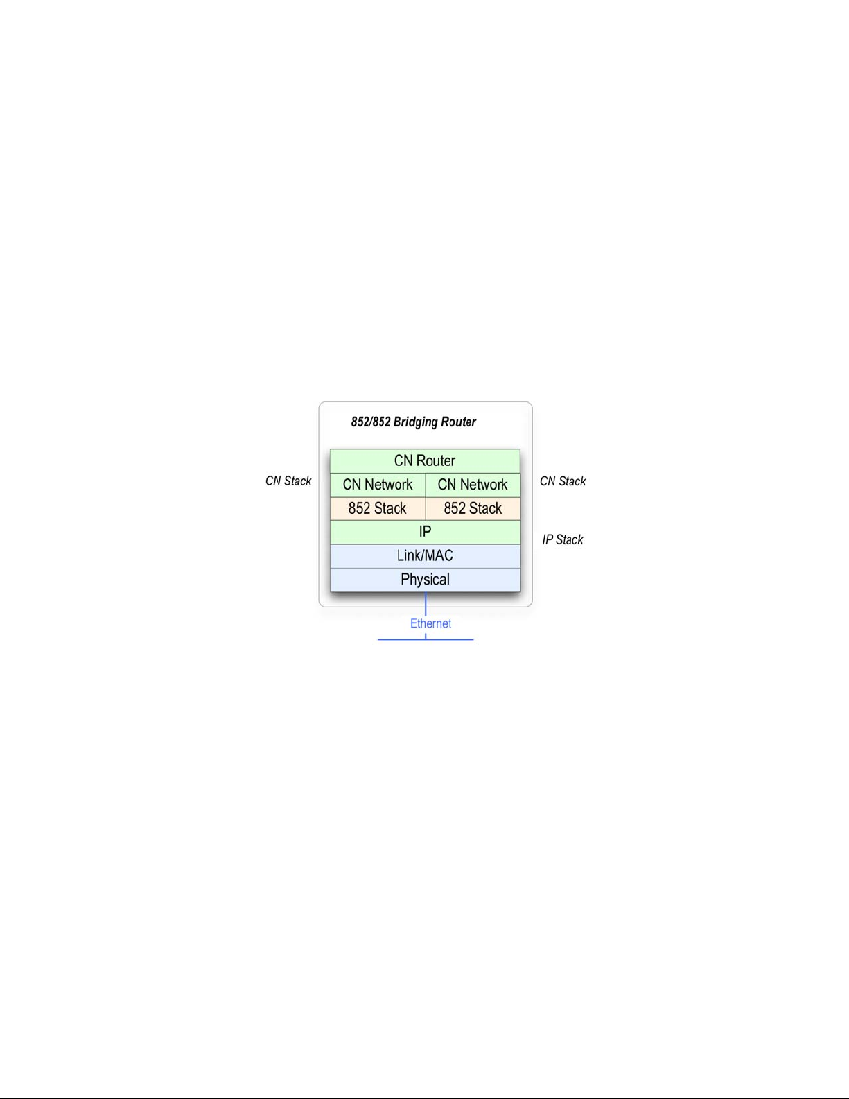
1.6. 852 to 852 Bridging Router Mode
In order to better support large installations with dozens of IP to LON routers a GRouter device
can be congured in 852 to 852 bridging router mode. In this mode one GRouter device can
bridge two logical 852 channels. When acting as an 852 bridge the router is a member of two
logical 852 channels sharing one ethernet interface. e router bridges trac between the two
channels. On the LON side the bridge looks like a LON router. is overcomes limitations of
some network managers on the number of 852 devices per channel and provides for enhanced
scalability by partitioning the 852 trac seen by any given router. Some network management
tools with an 852 interface have an articially low limitation on the number of 852 devices that
the tool can communicate with on its 852 channel. For low bandwidth 852 channels, Bridging
Router mode allows partitioning of the 852 devices so that the low bandwidth devices can be on a
dierent 852 channel from the high bandwidth devices.
e architecture of the GRouter in bridging router mode is shown below.
Fig.1.10: 852 Bridging Router Architecture
-14-
Page 15
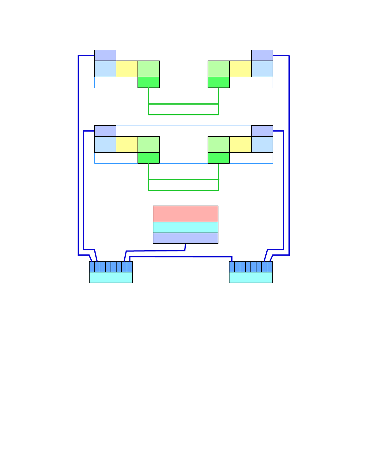
1.7. Redundant Twin Mode
e Twin Redundant Mode enables two GRouter devices to operate as a redundant pair for high
availability applications without generating duplicate trac. is enhanced capability increases
reliability and eliminates some single mode failure sources. A simple diagram showing a
redundant connection between two channels is shown below.
Router
IP/LON
709 with
852
709 with
LON
Ethernet
FTT-10
Router
IP/LON
709 with
852
709 with
LON
Ethernet
FTT-10
IP Ethernet Channel
709.1 FTT-10 Channel
Fig.1.11: Two redundant routers between the same channels
Although it is possible for a pair of conventional 709.1 routers to be identically congured and
connected between the same two channels, this conguration induces a doubling of the trac
between those two channels. e built-in duplicate detection mechanism in 709.1 discards the
duplicate packets at each receiving node. However, the doubled trac load could tax network
bandwidth and create other problems.
In Redundant Twin Mode (or for the sake of brevity, Twin Mode), both routers are identically
congured and connected between the same two channels as per the case described above but
unlike the case above only one of the two routers is forwarding packets. is feature achieves the
increased system reliability of having a redundant backup router without the drawbacks of
doubled trac. e Twin Mode routers monitor each others health and operational status and
dynamically activate forwarding as needed should one of the other fail. Failures are detected,
diagnosed, and reported so that repairs can be made to maintain continuous availability. Should
there be a fault in either interface then both routers will go active and forward trac until the
fault has been healed. In addition, the router conguration is periodically automatically
synchronized between the two routers to reduce fail-over time and increase the delity between
the backup and primary router operation. Also supported is manual synchronization which
makes it more convenient to replace one of the redundant pair and replicate its conguration. A
high availability building network can be constructed using pairs of redundant twin mode routers
and a redundant switched ethernet network. An example network showing the application of
Twin Mode is shown below.
-15-
Page 16
Redundant Twin
Routers
Router
IP/LON
Ethernet
852 709
FTT-10
Network Management Tool &
852 Configuration Server
Ethernet
852 Interface
Ethernet Switch
Ethernet 852 Channel A
Fully Switched
Ethernet 852 Channel B
Fully Switched
Ethernet Switch
A-1 B-1
FTT-10 Channel Ring
Router
IP/LON
Ethernet
852709
FTT-10
Redundant Twin
Routers
Router
IP/LON
Ethernet
852 709
FTT-10
A-2
B-2
FTT-10 Channel Ring
Router
IP/LON
Ethernet
852709
FTT-10
Fig.1.12: Redundant Twin Mode Application
-16-
Page 17

1.7.1. Denitions
For the purpose of clarifying the descriptions the following denitions are used:
Failure: A failure is detected whenever a heart beat times out without receiving a monitoring
packet from both interfaces. Only the active node sends monitoring packets. e inactive node
passively listens for the monitoring packets. e inactive twin always forwards monitoring
packets. In order for an active node to receive a monitoring packet it has to complete a round trip,
such as, out IP side to twin, in IP side of twin, out 709.x side of twin, in 709.x side, or going the
other way, out 709.x side to twin, in 709.x side of twin, out IP side of twin, in IP side. A failure
may be detected on one or both interfaces.
Fault: Once a failure is detected, both twins perform a diagnostic by actively interrogating each
other on both interfaces. If the interrogation on a particular interface fails then a fault has
occurred on that interface. An alarm is generated when a fault has been determined. A fault on a
particular interface is cleared whenever a monitoring packet is received or if a diagnostic
interrogation succeeds. A cleared fault generates an alarm cleared.
Both nodes independently report failures and faults. It is possible to have a failure but not a fault.
e converse is not true. It is possible for only one twin to report a failure. For example if either
interface has failed the active node will not receive any round trip monitoring packets so it will
report a failure on both interfaces. However it will only report a fault on one. In the same event
the inactive twin will report a failure on only one interface not both. e inactive will report a
fault on one interface.
Alternatively if one interface fails and then some time later the other interface fails, the initially
active twin will not diagnose the second fault. e initially inactive twin, however, will diagnose
the second fault. erefore in order to fully characterize the failure and fault state of a redundant
pair the state of both devices must be examined. Moreover, the monitoring application is on the
LON side. In the event of an IP failure the alarm SNVT sent by the active node may not be
received by a monitor HMI on the IP side. Although the alarm is sent out both sides, the IP side
has failed so the alarm can’t propagate on the IP side and the inactive twin may not have switched
to forwarding mode in time to forward the alarm packet. Nevertheless, the inactive device will
also detect the fault and its alarm will propagate.
1.7.2. Status SNVT
e twin monitoring application has a status SNVT type 93. If bound, the status SNVT is
propagated either on a timer, or when it is updated by the monitoring application, or both, or
neither. If propagate on update is o and the update time is zero then the status SNVT will
never be scheduled for propagation. In this case the only way to read the status SNVT is to poll it.
If propagate on update is o and update time is non zero then the status SNVT will propagate
at an interval specied by the update time. If propagate on update is on and update time is non
zero then the status SNVT will propagate both on the update time interval and anytime the status
is changed. If the update time is zero and propagate on update is on then the status SNVT will
only propagate when changed or updated by the monitoring application. Typically the status is
updated when the twin mode state changes.
e elds used in the status SNVT are as follows:
-17-
Page 18

comm_failure is set to 1 when there is either a monitoring failure or a diagnostic detects a fault.
comm_failure is not set to 0 until all failures and faults have cleared.
reserved2 is set based on the system state. See the following table.
Bit values for reserve2 status byte (big endian)
Bit Value
7 1 Active State, 0 Inactive State
6 1 Forwarding, 0 Dropping
5 1 Repair State, 0 Not Repair State
4 1 Diagnostic State, 0 Not Diagnostic State
3 1 IP side failure, 0 No IP side failure
2 1 LON side failure, 0 No LON side failure
1 1 IP side fault, 0 No IP side fault
0 1 LON side fault, 0 No LON side fault
1.7.3. Alarm SNVT
e monitoring application also has an Alarm2 SNVT type 164. is alarm is propagated
whenever a fault is detected or cleared. e elds used in the Alarm2 SNVT are as follows:
alarm_type is set to 1 whenever a diagnostic detects a fault. alarm_type is set to 0 when all faults
have cleared.
description is set to an ASCII text description of the associated fault state whether IP or LON
or both are cleared.
1.7.4. Status Report UNVT
e monitoring application has a status report UNVT that includes some extra information that
would not t in the Status SNVT. e status report UNVT is scheduled for propagation whenever
one of its elds is updated. It will only be propagated if bound or polled. e c structure for the
UNVT is as follows:
typedef struct
{
unsigned char Status;
char reserved[3];
uint32 totalArbs;
uint32 totalFailuresIP;
uint32 totalFailuresLON;
uint32 totalFaultsIP;
uint32 totalFaultsLON;
uint32 secsSinceClear; // seconds
uint16 forwardRate; // packets per second
char reserved[2];
} UNVTStatusType;
e elds are as follows:
-18-
Page 19

Status is an 8 bit number. e bit denitions are given in Table 1. It is the same information
reported in the Status SNVT reserved eld.
totalArbs is the total number of active state arbitrations since the last time the statistics were
cleared.
totalFailuresIP is the total number monitoring packet failures detected by this device of the IP
interface since the statistics were cleared.
totalFailuresLON is the total number of monitoring packet failures detected by this device of
the LON interface since the statistics were cleared.
totalFaultsIP is the total number of diagnostic faults detected by this device of the IP interface
since the statistics were cleared.
totalFaultsLON is the total number of diagnostic faults detected by this device of the LON
interface since the statistics were cleared.
secsSinceClear is the count of seconds since the statistics were last cleared.
forwardRate is computed as the total number of packets forwarded divided by the number of
seconds since the forward rate was last calculated. e forward rate is updated whenever the
UNVT is updated and at least one second has expired since the last update.
-19-
Page 20

1.8. System Requirements and Connections
1.8.1. System Requirements
To congure the GRouter device, you will need a web browser such as FireFox, Mozilla, Safari, or
Internet Explorer.
e GRouter device will communicate with any of the following:
• Adept Systems Inc. GRouter4, GRouter3, or GadgetGatewayIa (GG1a) 852 router
• Echelon i.LONTM router or LNS VNI based tool such as LonMaker
TM
• Coactive Router-LL router
• Any 852B or later compliant node
To operate in normal mode an 852B conguration server is required such as the free Echelon
i.LON conguration server. Manual mode does not require a conguration server.
Note: e GRouter and Router-LL routers can interoperate in either Manual mode or with the
Router-LL conguration server.
e Adept Systems GRouter device also needs the following hardware:
• Cat 5 Ethernet Cable (for Ethernet versions).
• Regulated 5V DC power supply.
• Twisted pair cable for 709.1 (LON) port.
Up to date documentation and rmware is available on Adept's web site at
http://www.adeptsystemsinc.com.
-20-
Page 21
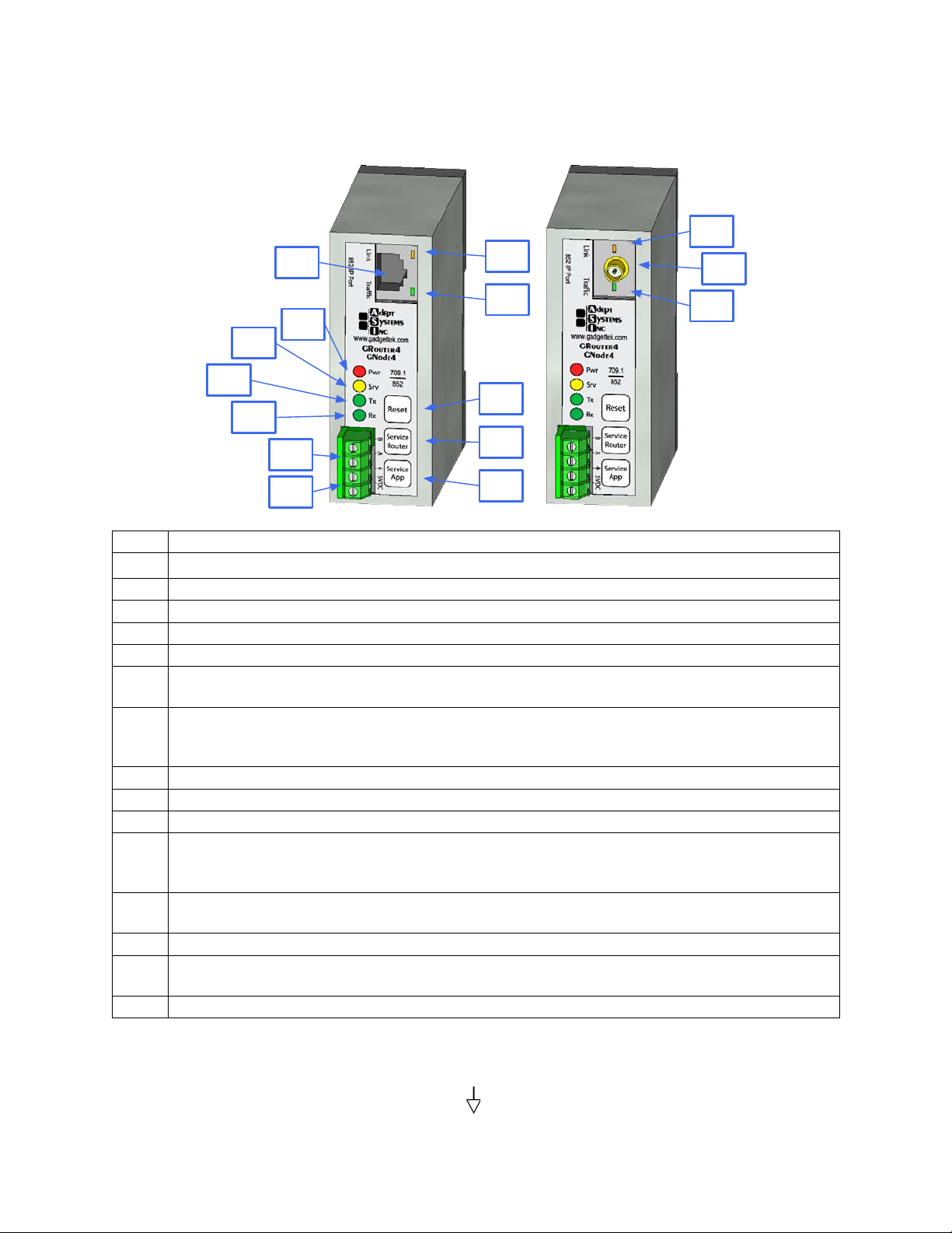
1.8.2. Button, Indicators, and Connectors for GRouter
1
8
9
2
3
4
5
6
7
10
11
12
13
14
15
Index Description
1 Ethernet 10/100 Base-T Port. RJ-45 Cat-5.
2 Power LED lights when unit powered.
3 Service LED ashes when a service message sent.
4 TX LED ashes to indicate send trac on the LON Port.
5 RX LED ashes to indicate receive trac on the LON Port.
6 LON (709.1) Port. May be either FTT-10 or RS-485 transceiver. Check particular conguration of router. 2
Pin, 5mm spacing screw terminal block.
7 5 V power input and ground. Ground pin is also ground for RS-485 transceiver when applicable. Requires
regulated 5V. Reverse polarity protected. Reversing polarity for extended time may damage router. 2 Pin,
5mm spacing screw terminal block.
8 Ethernet Link LED lights when link obtained.
9 Ethernet Trac LED ashes when trac on Ethernet port.
10 Reset Button. Resets and restarts router.
11 Service Pin Router. Sends out a service message on both LON and IP sides for the router. If 852 bridging
router mode is enabled sends out a service message for both 852 channels. Also used for startup mode
selection.
12 Service Pin Application. Sends out a service message on both LON and IP sides only if optional twin mode
application is activated. Also used for startup mode selection.
13 WiFi Link LED lights when link obtained.
14 WiFi Port for optional 802.11b WiFi version. Male RP-SMA screw connector. Mates with Female RP-SMA
antenna or cable.
15 WiFi Trac LED ashes when trac on WiFi port.
1.8.3. Wiring
e standard conguration for the GRouter4 has a 4 pin 5.0 mm spaced screw terminal block.
e pins from top to bottom are labeled A, B, (logic ground), and 5VDC. To use the terminal
-21-
Page 22
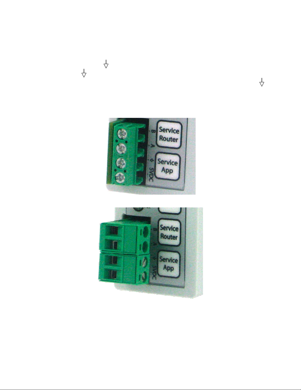
block unscrew the terminal screws on the block and insert the ends of the appropriate wires into
each opening. Tighten the terminal screws. Pins A and B are the 709.1 LON channel port pins.
For FTT-10 transceivers, use the A and B pins. e pins are polarity insensitive. For RS-485
transceivers use the A and B pins appropriately and insert the RS-485 ground lead into the
terminal block pin with the (ground) symbol next to the pin labeled A. ere are two power
input pins labeled (logic ground) and 5VDC. e GRouter4A requires regulated 5 Volt DC
positive on the 5VDC pin. Attach the ground pin from the power supply to the pin labeled .
e power input is polarity sensitive but does have reverse polarity protection. If aer powering
up the 5V input, the power LED does not light up, disconnect power and check the polarity of the
input power wires before recycling power. Applying a reverse voltage for an extended time period
may damage the GRouter4.
Fig.1.13: Front terminal block detail with standard connector
Fig.1.14: Front terminal block detail with optional pluggable connectors
1.8.4. FTT-10 XCVR LonTalk Network Termination
When using an FTT-10 XCVR, the network wiring should be terminated or performance may
suer. is is especially true for long wire runs or noisy environments. Typically an external
terminator is used. e GRouter4, however, does have an optional internal terminator for those
applications where it is desirable or convenient to terminate at the router. When the optional
-22-
Page 23

internal terminator is installed, a jumper on header JP1 is used to congure the type of
termination. In order to do this the case must be opened. Disconnect the power and network
before opening the case. Use caution and appropriate electrostatic safety precautions whenever
working with the case removed. If the center pin of JP1 is jumpered to the pin labeled Free, then
the terminator is set for free topology mode. If the center pin of JP1 is jumpered to the pin labeled
Bus, then the terminator is set for bus mode. If the center pin is not jumpered to either the Bus or
Free pins then the terminator is disabled. e following gures show photos of JP1 withe the
jumper in the 3 dierent settings.
Fig.1.15: Optional internal terminator disabled
Fig.1.16: Optional internal terminator set to Free Topology mode
Fig.1.17: Optional internal terminator set to Bus mode
-23-
Page 24

2. Web Conguration
e Web-based GRouter device interface allows the user to access and change conguration data
on the GRouter device by using any http Web browser attached to the network. is allows users
to make changes to the GRouter device remotely. is chapter familiarizes the user with the
various pages of the Web-based Interface and describes the steps necessary to changing
conguration data.
2.1. Default IP Conguration
e GRouter device is congured through a web browser such as FireFox, Internet Explorer,
Safari, or others. In order to connect to the GRouter device from a web browser, the GRouter
device and the computer running the web browser must be connected to the same IP network.
e factory default IP host address of the GRouter device is 10.0.2.40 with subnet mask of
255.255.255.0. e router's web server is serving http on port 80. e computer running the web
browser must be able to access the GRouter device's subnet.
2.1.1. Ethernet
For Ethernet equipped GRouter devices, rst congure the host computer to add an IP interface
on subnet 10.0.2.0/255. Connect one end of a Cat5 Ethernet cable to the RJ-45 on the GRouter
device and the other end to an Ethernet hub or switch or directly to a computer with a crossover
cable or straight through if the computer’s Ethernet port supports auto crossover (Auto MDIX).
e GRouter Ethernet port is MDI only. In cases where the LAN does not support the default
subnet, a direct connection between the GRouter device and the web browser host computer will
be needed.
Network Hub or Switch
Cat5
Cat5
Fig.2.1: Ethernet setup with hub or switch
-24-
Page 25

Cat5 CrossOver Cable
Fig.2.2: Ethernet with direct connect crossover cable
2.1.2. WiFi (802.11b)
For WiFi equipped GRouter devices, an 802.11b WiFi access point or ad hoc connection must be
setup between the web browser host computer and the GRouter device. First congure the host
computer to add an IP interface on subnet 10.0.2.0/255. en setup the WiFi conguration. e
default WiFi conguration for the GRouter device is as follows:
Wireless SSID: "Adept"
Wireless Mode: Any Type (Ad hoc or Infrastructure)
Channel: Search
Encryption: None
e access point or ad hoc connection must be set up to allow a connection on a network with
SSID of Adept or Any. ere are many dierent topologies that may be employed for connecting
to the GRouter (GRouter) WiFi version. e following gures show some of the more common
ones.
Ethernet
Fig.2.3: WiFi setup with access point and Ethernet connection to host computer
-25-
Page 26

Ethernet
Ad Hoc Bridge
Fig.2.4: WiFi setup with ad hoc bridge and Ethernet connection to host computer
Fig.2.5: WiFi setup with ad hoc WiFi card on PC
Access Point
Fig.2.6: WiFi setup with access point and WiFi card on PC
-26-
Page 27

2.1.3. Establishing Connection
Once the IP connection (WiFi or Ethernet) is setup, power up the GRouter device. It takes about
60 seconds for the GRouter device to boot up. Boot-up has completed when the yellow User LEDs
start ashing. To verify that the IP connection has been made send an IP ping to the GRouter
device default IP host address (10.0.2.40). In Linux, Windows 2k+, or Mac OS X a ping can be
sent from the command line as follows:
ping 10.0.2.40
en type enter or return.
If there is no response double check all network connections and cables. Once you can
successfully ping the GRouter device, establish a web connection from a web browser window as
follows:
http://10.0.2.40
en type enter or return.
e GRouter device web interface will prompt for a user name and password. e default user
name is Adept and the default password is Gadget. e user name and password are case sensitive
so make sure to use a capital A and capital G respectively. Click OK. You will now be shown the
home or status page for the GRouter device web based Conguration Tool. To navigate the
various pages in the Tool, simply click the buttons on the le side of the page to link to the
appropriate page. e button corresponding to the page that is currently displayed will be
highlighted in pink. Each of the pages in the web based Conguration Tool will be explained in
the following sections.
Fig.2.7: User Name and Password Authentication
Once communications have been established, new IP or WiFi parameters may be entered. e
procedure is as follows:
• Set up IP and/or WiFi interface between host computer and GRouter device using default
network settings
• Recongure the GRouter device to use new network settings
• Recongure the IP and or WiFi network to use new settings
-27-
Page 28

• Reboot GRouter device and reestablish communications using new settings
• If communications with new settings cannot be established because of lost or incorrect
settings then revert GRouter device to factory defaults and start over.
2.1.4. Restoring Factory Defaults
e web Tool allows customization of the IP address, net mask, http port, user name, and
password. Should any of these settings be forgotten or setup incorrectly, communication with the
GRouter device may not be possible. In this event, the GRouter device can be restored to factory
defaults so that a known set of IP parameters is in eect. ere are three sets of default settings.
Each is reset using the same approach except that a dierent service button or combination of
service buttons is held down at system powerup or reset.
2.1.4.1. Basic Procedure
e basic procedure is to press and release the Reset button or power cycle the GRouter device
and then press and hold down without releasing one or both (as appropriate) of the two service
buttons on the front panel. While the GRouter boots up the Srv, Tx, and Rx LEDs on the front
panel will be o. Aer about a minute, when the GRouter completes boot up, the Srv, Tx, and Rx
LEDs will all go on steady for a couple of seconds then go o for a second and then on again. At
this point release the service button(s) and the Srv LED will go o, the Tx and Rx LEDs will stay
on steady if there is no trac or will icker if there is trac. e GRouter will now automatically
reboot one more time. Once the GRouter completes this last reboot (aer about a minute or two)
the appropriate default settings will have been restored.
Test the restored IP settings by pinging the default IP address and/or entering the default URL
into a web browser.
2.1.4.2. IP and WiFi settings
To restore the IP host address, netmask, and, when applicable, the WiFi interface settings to
factory defaults use the basic procedure above and hold down the button labeled "Service Router".
2.1.4.3. Web user name, password, and http port
To restore the web user name, password, and http port settings to factory defaults use the basic
procedure above and hold down the button labeled "Service App".
2.1.4.4. All parameters
To restore all the parameters (IP, WiFi and web) to factory default settings use the basic procedure
above and hold down both buttons labeled "Service Router", and "Service App" respectively.
-28-
Page 29

2.1.5. WiFi Setup in Windows XP
• Go to the network connections control panel. Right click wireless connection and select
properties.
• Select the general tab. Set the IP address to one that is in the same subnet as the GRouter’s
default IP of 10.0.2.40 with a subnet mask of 255.255.255.0. For example you could use
10.0.2.41.
• Go to network properties and select the connection tab. Select manual connect to an available
wireless network not automatically connect.
• In the main network connections control panel, create a new wireless network by selecting
"add new network". Use the following settings the the network:
◆ In the Association Tab set the following elds:
■ SSID: "Adept"
■ Network Auth: open
■ Data Encryption : Disabled
■ Check the "this is a computer to computer network(ad-hoc)" box.
◆ In the Authentication Tab leave the settings at the defaults.
◆ In the Connection Tab set the following:
■ Check the "connect when this network is in range" box.
• Click Ok, then Ok again to save the settings.
• Aer a minute or two the computer will automatically connect to the GRouter
• You can now access the GRouter's conguration web pages through a web browser using a url
of "http://10.0.2.40".
-29-
Page 30

2.2. Status Page
e status page is the home page for the web Tool. e buttons shown on the le will vary
depending on what optional services have been enabled in the router. e Router Status Page
displays basic information about the status of the Router. Changes to the data cannot be made
through this page; it is for information purposes only. Following is a brief description of each
item shown on the page
Fig.2.8: Status Page
NAME: e given name of the router.
FIRMWARE VERSION: e version of the rmware currently loaded on the router.
SERIAL NUMBER: e serial number for the router.
DEVICE CODE: e unique device code for the router.
-30-
Page 31

IP MAC ADDRESS: e IP MAC or hardware address assigned to the router's IP port.
IP ADDRESS: e IP address assigned to the router.
NODE ID (709.1): e 709.1-side (LON) unique Node ID number assigned to the router. If 852
bridge mode is enabled this is the near side of the router.
NODE ID (IP): e IP-side unique Node ID number assigned to the router. If 852 bridge mode is
enabled this is the far side of the router.
NODE ID (App): If Twin-Mode is enabled, the unique Node ID number assigned to the
monitoring application.
MODE: e current operating mode of the router. e two possible modes are Manual, and
Normal.
DATE DAY of WEEK and TIME: e date, day of week, and time currently stored on the router is
displayed in these elds.
Change Date/Time: Enter the desired Date, Day of Week, and Time in the appropriate elds.
Click the Update Date/Time button. is will update the current values stored in the real time
clock.
Enable Twin Mode Key: Enter in this eld the 16 character key to unlock the Redundant Twin
Mode feature. Click the Update Keys button. e feature should be immediately available and the
enhanced feature list at the bottom of the page should then include Redundant Twin Mode.
Enable Bridge Mode Key: Enter in this eld the 16 character key to unlock the Bridging Router
Mode feature. Click the Update Keys button. e feature should be immediately available and the
enhanced feature list at the bottom of the page should then include Bridging Router Mode.
Update Keys: is button processes the the enhanced feature keys elds and activates the
associated features.
e bottom of the page lists the enhanced features supported by this router. ese may include
one or more of the following: DDNS Support, NAT Router Support, Redundant Twin Mode, 852
Bridging Router Mode.
-31-
Page 32

2.3. Router Setup Page
e Router Basic Setup Page is used to set up basic conguration properties of the router.
Following is a brief description of each item listed on the page, as well as instructions on how to
set or change items.
2.3.1. Normal Mode Router Setup
When not in bridging mode the Normal mode router setup page looks like the following.
Fig.2.9: Router Setup Page
MODE: is displays the current operating mode of the router. To change the router mode, select
the radio button that corresponds to the desired mode and then click the “Submit Changes”
button. e two possible modes are Manual, and Normal.
-32-
Page 33

• Manual Mode: Use manual mode when precise control over the Channel List is desired. In
manual mode the user is responsible for the conguration of the Channel List.
• Normal Mode: Use normal mode when the router is being congured by a remote
conguration server. When in Normal mode, ensure that the Cong Server Address is correct
(see Cong Server Address below).
Router Name: is eld allows the user to set or change the name of the router. A descriptive
name can be used to give the network administrator information on the location and use of the
router (for example, Name: router Room 34). To change the name of the router, type the new
name into the eld provided and click the “Submit Changes” button.
Router Type: is popup menu eld allows the user to set or change the type of the router. e
three choices are Congured, Repeater, and Flood. Select the new value and click the “Submit
Changes” button.
• Congured: Selecting this router type will cause the GRouter device to lter trac. e lter
rules are based on router tables set on the GadgetGateway by a LON management tool or by
the web Tool
• Repeater: Repeater mode will drop packets that fail their CRC checks or packets that do not
belong to one of the router's domains. Network management packets addressed to the router
are not passed but are handled by the router. Otherwise all packets on either side will be
forwarded to the other side of the router.
• Flood: Selecting this router type will cause the router to forward all packets including network
management packets (except those that fail CRC). No other ltering is done. In Flood mode
the router is completely transparent to the 709.1 channel. is enables tunneling over IP of
some 709.1 networks with odd congurations. Flood type can only be congured in manual
mode. Any 709.1 networks connected to GRouter devices in Flood Mode become one large
virtual subnet. In contrast with Congured and Repeater modes, Flood mode makes two
GRouters appear as essentially a physical layer repeater with two major exceptions:
◆ 1) Packets with CRC errors are discarded.
◆ 2) Unlike a good physical layer repeater, the gateway can be saturated.
When in Flood Mode, 709.1 network management tools will not be able to communicate with
the GRouter device. e router is completely transparent to all 709.1 devices.
IP Port: is eld allows the user to set or change the unicast IP port of the router. Enter the new
value and click the “Submit Changes” button. e designated default port for 852 client devices is
1628.
NAT Router WAN Address: is eld allows the user to set or change the WAN IP address of a
NAT router. is is only applicable when the router is connected to the internet through a NAT
router and needs to communicate with 852 devices on other LANs. To change the value in the
eld, type in the new value in the dotted format XX.XX.XX.XX and click the “Submit Changes”
button. When using a NAT router as the internet interface for the LAN upon the GRouter device
is connected, the NAT router’s WAN IP address must be static (unless Dynamic DNS is used).
-33-
Page 34

e GRouter device’s LAN address must also be static and the 852 port must be mapped by the
NAT router.
NAT Router Support: ese radio buttons allow the user to set or enable or disable NAT router
support. When enabled the node substitutes the NAT Router WAN Address as the source address
in appropriate packet headers so that other 852 nodes can respond through the NAT Router. is
enables 852 devices that are on other LANs on the WAN side of the NAT router to correctly
respond to the local GRouter device. It may or may not be possible to have two GRouter devices
on the same LAN side of a NAT Router when NAT support is enabled. Each GRouter would need
to have a unique 852 port number mapped by the NAT Router and the NAT router would have to
be able to support local loopback of WAN addressed packets. Select the new value and click the
Submit Changes button.
852 Bridging Mode: is displays and controls the status of the 852 Bridging Router mode for the
router. ese buttons only appear if the router has Bridging Router Mode support activated on
the Status Page. To enable or disable 852 bridging mode, select the radio button that corresponds
to the desired state, On for enable, O for disable, and then click the Submit Changes button.
Finally select the Reboot button. A description of the conguration of Bridging Router Mode is
provided in a later section.
Compatibility Mode: is popup menu eld allows the user to change the conguration server
compatibility mode. e three choices are Standard 852, i.Lon Cong Server, and CoactiveLL
Cong Server. Select the new value and click the “Submit Changes” button.
e router-LL cong server and some versions of the i.LON cong server and were developed
before the nal version of the ANSI/EIA 852 specication was nalized. Consequently there are
variations in how they function.
• 852 Compliant Mode: Select when using a fully 852 compliant conguration server.
• i.LON (TM) CongServer Compatibility Mode: Select when using version 1.x of the i.LON
conguration server.
• Coactive Router-LL (TM) CongServer Compatibility Mode: Select when using the Router-LL
conguration server.
CongServer Address: is eld requires information only when the router is operating in
Normal mode (See “MODE” above). is is the unicast IP host address of the conguration
server for this channel. To change the value in the eld, type in the new value in the dotted format
XX.XX.XX.XX and click the Submit Changes button.
CongServer Port: is eld requires information only when the router is operating in Normal
mode (See “MODE” above). is is the IP unicast port of the conguration server for this
channel. To change the port, type in the new port number (0-65535), and click the Submit
Changes button. e default designated port for 852 servers is 1629.
Serial Transaction Mode: ese radio buttons allow the user to enable or disable Serial
Transaction Mode. When enabled the Router will send out 852 conguration updates serially in a
round robin fashion to the other 852 devices on the channel instead of in parallel. is means that
an update transaction has to complete or time-out with one device before a new transaction is
started with the next device. is mode signicantly reduces bursts of trac when devices are
-34-
Page 35

added to a channel or their routing data is changed. is may be helpful for low bandwidth 852
channels. Select the new value and click the Submit Changes button.
Serial Transaction Interval: is eld sets the time interval between successive conguration
transactions when Serial Transaction Mode is enabled. e default is 1000 ms. is enables the
user throttle the rate at which conguration updates are sent out on the channel and thereby
manage trac. is may be helpful for low bandwidth 852 channels. Enter the new value and
click the Submit Changes button.
Loop Detect Interval: is value determines the number of milli-seconds between transmission of
a loop detection packet. A value of zero disables this feature. e default value is 5000 ms or 5
seconds. Setting this value to much below 1000 is not recommended. If the Loop Detection nds
a loop in the network routing, it will cause the GRouter to go uncongured to prevent runaway
trac. A loop is detected if the router receives its own loop detection message on the opposite
side of the router. e router will continue to send loop detection messages and will resume
operation once the loop condition is removed. Click Submit Changes and the new value is
immediately in eect.
Loop Recover Retries: is value determines the number of unsuccessful retires of the loop
detection message before a loop condition is considered to have been remedied. e default is
three. e minimum allowed value is two. Click Submit Changes and the new value is
immediately in eect.
Redundant Router Detect: ese radio buttons allow the user to enable or disable the detection of
redundant 852 routers on the 852 channel. When enabled, no CN data packets are forwarded to
any redundant routers. is prevents loops due to redundant routers from occurring. Click
Submit Changes and the new value is immediately in eect.
Loop Check on Boot: ese radio buttons allow the user to change the boot up mode of the router
with respect to loop detection. When enabled, the router will not forward CN data packets until
aer a loop check has completed and no loops were detected. is adds an additional delay at
boot-up before the router will begin forwarding packets. e length of the delay is equal to the
Loop Detect Interval times the number of Loop Recover Retries. When disabled, the router will
immediately begin forwarding packets on boot-up. Click Submit Changes and the new value is
immediately in eect.
Submit Changes: is button updates all the conguration information entered on the current
web page and refreshes the display.
Trigger Service Pin: is button causes a service pin message to be sent out both the 709.1 and IP
interfaces of the router. is can be used when commissioning the router remotely.
Register With Cong Server: is button sends an 852 registration request to the cong server.
is will usually add the device to the cong server’s list of managed devices.
Launch Upgrade FTP Server: is button starts up the FTP server needed to perform eld
upgrades of the GRouter device's rmware. A detailed description of the upgrade process is
provided in a later section.
Clear Router Cong: is button clears all router conguration information, such as routing
tables, back to factory defaults. It does not aect the web or IP address or interface. is is useful
-35-
Page 36

when moving the router to a dierent 852 channel or conguration and a known starting
conguration is desirable..
Reboot: is button performs a so reboot of the main processor on the router. is is needed any
time the ports are changed or the 852 Bridge mode is changed. When rebooting the following
page will be displayed.
Fig.2.10: Reboot Page
Once rebooting has completed reenter http://10.0.2.40 or whatever the IP address of the router is
to go back to the Status page.
2.3.2. Manual Mode Router Setup
When in manual mode the router setup page is the same as the Normal mode except that the
compatibility mode, conguration server IP address, and, port elds are not displayed.
-36-
Page 37

2.3.3. Bridging Router Setup
When 852 to 852 bridging router mode is enabled the GG router has two IP side 852 interfaces.
One is labeled the Side A and the other the Side B. Both interfaces share the same IP host address
but each interface has a unique IP port and a unique conguration server (when in Normal
mode). Each side can be in either Normal or Manual mode independently. In addition, Serial
Transaction Mode can be independently enabled or disabled on each side. e description below
only includes those elds that are unique to Bridging Router mode. When 852 bridge mode is
enabled there could be up to two conguration servers, one for each of the bridged channels, that
is, Side A and Side B.
When 852 to 852 Bridging Router Mode is enabled, the router setup page looks like the following.
-37-
Page 38

Fig.2.11: Bridging Router Mode Setup Page
-38-
Page 39

Side A Data IP Port: is eld appears when the router is in 852 bridge mode. It allows the user
to set or change the Side A unicast IP port of the router. To change the port, type in the new port
number (0-65535), and click the Submit Changes button.
Side A CongServer IP Address: is eld appears only when the router is operating in 852
Bridge mode and Side A is in Normal Mode. is is the unicast IP host address of the
conguration server for the Side A 852 channel. To change the value in the eld, type in the new
value in the dotted format XX.XX.XX.XX and click the Submit Changes button.
Side A CongServer IP Port: is eld appears when the router is in 852 bridge mode and Side A
is in Normal mode. It allows the user to set or change the Side A unicast IP port of the cong
server for the Side A 852 channel. To change the port, type in the new port number (0-65535),
and click the Submit Changes button.
Side B Data IP Port: is eld appears when the router is in 852 bridge mode. It allows the user
to set or change the Side B unicast IP port of the router. To change the port, type in the new port
number (0-65535), and click the Submit Changes button.
Side B CongServer IP Address: is eld appears only when the router is operating in 852 Bridge
mode and Side B is in Normal Mode. is is the unicast IP host address of the conguration
server for the Side B 852 channel. To change the value in the eld, type in the new value in the
dotted format XX.XX.XX.XX and click the Submit Changes button.
Side B CongServer IP Port: is eld appears when the router is in 852 bridge mode and Side B
is in Normal mode. It allows the user to set or change the Side B unicast IP port of the cong
server for the Side B 852 channel. To change the port, type in the new port number (0-65535),
and click the Submit Changes button.
Register With Cong Server: is button sends an 852 registration request to the appropriate
cong server for Side A and separately to the cong server for Side B when either/both Side A
and Side B are in normal mode. is will usually add the device to the cong server’s list of
managed devices.
-39-
Page 40

2.4. IP Setup Page
e IP Setup Page displays status additional information about the Gateway's IP setup not
included in the Router Setup page. Following is a brief description of each item listed on the page,
as well as instructions on how to set or change items. In normal mode the page looks like the
following.
Fig.2.12: IP Setup Page
MAC Address: e physical address of the Ethernet interface in HEX. is is a read only eld.
IP Address: e IP address currently assigned to the Gateway. is is the unicast IP host address
of the router. To change the value in the eld, type in the new value in the dotted format
XX.XX.XX.XX and click the Submit Changes button. e IP host address change will not take
eect until aer the router is rebooted. Be careful to record the new address as it will not be
possible to communicate with the GRouter without a valid IP address.
Subnet Mask: e IP subnet mask assigned to the router. To change the value in the eld, type in
the new value in the dotted format XX.XX.XX.XX and click the Submit Changes button. e
subnet mask change will not take eect until aer the router is rebooted.
Gateway: e address of the IP router or gateway used by the GRouter device to reach other
devices that are not in its local network. To change the value in the eld, type in the new value in
the dotted format XX.XX.XX.XX and click the Submit Changes button.
Web-Server Port: is eld allows the user to change the IP port used by the embedded web
server on the device. e default is port 80. When used with a NAT router and port mapping,
-40-
Page 41

port 80 may be in use by another device. e device must be restarted before changes to the webserver port will be activated. To change the value, type in the new value and click the Submit
Changes button and then click the Reboot button. A typical alternate web server port is 8080. To
access the web server on any port other than 80, use the following format in the web browser:
http://IP Address:Port
for example
http://10.0.2.40:8080
Reboot: is button performs a so reboot of the main processor on the router. is is needed for
any of the changes on this page to take eect. When rebooting the Rebooting page will be
displayed (see previous section). Once rebooting has completed re enter the http address and port
for the web server to go back to the home page.
-41-
Page 42

2.5. WiFi Setup Page
For GRouter devices equipped with WiFi IP interfaces the WiFi setup button will appear and will
display the WiFi setup page.
MODE: is displays the WiFi channel access mode of the router. To change the WiFi mode,
select the the desired mode in the popup menu and then click the Submit Changes button. e
mode will not change until aer a reboot. e Four possible modes are Any type, Infrastructure,
Ad hoc (join or create), and Ad hoc (join only).
• Any Type: Will attempt to connect on each of access modes until it nds one with the chosen
SSID.
• Infrastructure: Use this mode for connecting to an access point.
-42-
Page 43

• Ad hoc (join or create): Use this mode for creating an ad hoc network if one does not exist or
joining one that already exists with the chosen SSID
• Ad hoc (join only): Use this mode for joining an existing ad hoc network
SSID: To change the SSID of the WiFi channel, type the new value into the eld provided and
click the Submit Changes button.
Channel: To change the WiFi channel number select it from the popup menu. To search for an
available channel, select Search. In search mode, the router will search all channels until it nds
one with the chosen SSID. Select the new value and click the Submit Changes button.
WEP: Select the appropriate radio button. e two choices are Enabled and Disabled. Select the
new value and click the Submit Changes button. WEP may not be enabled when WPA is enabled
and vice versa.
Default Key: WEP stores four dierent keys that may be used to join a WEP protected network.
Only one key is needed for any network . Select which key from the popup menu and click the
Submit Changes button.
KEY 0 - KEY3: To change the WEP Key of the WiFi channel, type the new value into the eld
provided and click the Submit Changes button. e length of the key may be either 13 Hex digits
(for 64 bit encryption) or 26 Hex digits (for 128 bit encryption). e length needed is determined
by the access point or ad hoc network settings.
WPA: Select the appropriate radio button. e two choices are Enabled and Disabled. Select the
new value and click the Submit Changes button. WEP may not be enabled when WPA is enabled
and vice versa.
Passphrase: To change the WPA passphrase of the WiFi channel, type the new value into the eld
provided and click the Generate WPA PSK from Passphrase button. e length of the passphrase
must be between 8 and 63 characters inclusive.
Generate WPA PSK from Passphrase: is button generates the WPA key from the given
passphrase.
User Name: To change the WPA logon user name, type the new value into the eld provided and
click the Submit Changes button.
Password: To change the WPA logon password for the given user, type the new value into the eld
provided and click the Submit Changes button.
Submit Changes: is button updates all the conguration information entered on the current
web page and refreshes the display.
Reboot: is button performs a so reboot of the main processor on the router. None of the WiFi
parameter changes will be put into eect until aer a reboot. Take care when making changes as
an errant conguration may result in loss of communication and no access to the conguration
pages. e only way to restore communications may be to reset to factory defaults.
-43-
Page 44

2.6. 709 Setup Page
e 709 Setup Page is used to set up the 709.1 protocol specic properties of the router. is
information includes the subnet address, node address, domain address, node ID and node state
numbers for both sides of the router and the twin mode monitoring application (when enabled)
as well as the subnet and group forwarding tables. Following is a brief description of each item
listed on the page, as well as instructions on how to set or change items. e main top section of
the page looks like the following.
Fig.2.13: 709 Setup Page Main Section
2.6.1. Node Parameters
e management of these parameters is usually performed by a management tool such as
Echelon's LonMaker®. If you are using a management tool, it is recommended that these
parameters not be changed manually. However, the Interface Menu does allow users to change the
interface parameters manually, if desired. Not all node parameters are editable from this interface
and consequently a node may not be fully congured such as group membership. is capability
is provided for debugging or other special circumstances where a network management tool is
not available and minimal functionality is needed.
ere are three 709 interfaces or stacks on the GR4. ese are called Side A, Side B, and
Application. e Applications refers to the Twin Mode application when enabled. Each interface
is qualied in parenthesis to the type of channel, IP or component network LON. When in
bridging router mode both Side A and Side B are IP and the LON interface is disabled. .
•
Domain Index: A 709.1 node may be a member of two domains. In each domain a node may have
a distinct subnet and node number. Choose the domain index to edit then Click Submit Changes.
-44-
Page 45

Subnet: When a node is uncongured the subnet may be zero. Valid congured subnet numbers
are from 1 to 255. Enter the subnet number then click Submit Changes.
Node: When a node is uncongured the node number may be zero. Valid congured node
numbers are from 1 to 127. Enter the node number then click Submit Changes.
Domain Number: e number of valid domains is a function of the Domain Length. Zero is a
valid domain number but is reserved for network management. Enter the Domain Number then
click Submit Changes.
Domain Length: e Domain Length may be 0, 1, 3, or 6 bytes long. Choose the Domain Length
from the popup menu then Click Submit Changes.
Node State: e Node State determines whether the node operates in Congured or Uncongured
mode. In manual mode the default state for a new device is Uncongured. Setting the state to
Uncongured allows you to temporarily disable the device while editing the forwarding tables.
Choose the Node State from the popup menu then click Submit Changes.
NodeID: e NodeID is a unique 48 bit number assigned to each 709.1 node. is is a read only
eld in hexadecimal notation.
Submit Changes: is button updates node parameter information for the current interface and
refreshes the display.
Interface: To select which interface is to be edited, choose the interface from the popup menu and
then click the Change Interface button.
• Side A (LON): Selects the Side A interface for editing.
• Side B (IP): Selects the Side B interface for editing.
• Application: Selects the TwinMode Application interface for editing
Change Interface: is button which interface to edit and refreshes the display.
2.6.2. Forwarding Tables
e 709 Setup Page also allows the direct setting of the 709.1 subnet and group forwarding tables.
is is most useful in manual mode or in situations where a special conguration is needed. e
forwarding table portions of the page are shown below.
For each table the bits are displayed from le to right in increasing order of bit position. Bit
position one refers to subnet number one and so forth. Clicking on a bit will toggle the bit value
and store the new value in memory. A value of one in a bit position means forward packets
addressed to the corresponding subnet or group. A value of zero in a bit position means do not
forward packets addressed to the corresponding subnet or group.
Clear Subnet Table: is button clears all the subnet bits by assigning each a value of zero and
stores the new values in memory.
Set Subnet Table: is button sets all the subnet bits by assigning each a value of one and stores
the new values in memory.
Clear Group Table: is button clears all the group bits by assigning each a value of zero and
stores the new values in memory.
-45-
Page 46

Set Group Table: is button sets all the group bits by assigning each a value of one and stores the
new values in memory.
Fig.2.14: Subnet Forwarding Table
Fig.2.15: Group Forwarding Table
-46-
Page 47

2.7. Channel List Page
In Normal mode the Channel Membership List is controlled by the conguration server. Whereas
in Manual mode the Channel Membership List must be congured manually. is page allows
the user to add and delete the devices from the 852 channel when in Manual mode. Following is a
brief description of each item listed on the page, as well as instructions on how to set or change
items. e behavior of the page is dierent for Normal and Manual mode.
2.7.1. Normal Mode Channel List Page
In Normal mode, the page looks like the following.
Fig.2.16: Channel List Page
-47-
Page 48

Channel Date Time: is is the 852 DateTime when the Channel Membership List was last
changed. is is a read only eld for debugging purposes. In Normal mode, this value is governed
by the conguration server.
Channel Time Out: is is the 852 Channel Time Out. is is a read only eld for debugging
purposes. In Normal mode, this value is governed by the conguration server..
Channel Address Mode: Is either Unicast or Multicast. Multicast is only supported in manual
mode. In normal mode, this value is governed by the conguration server.
Packet Escrow: ese radio buttons enable or disable Packet escrow mode. Packet escrow is used
to escrow and reorder any out of order 852 IP CN Data packets during the escrow time.
Escrow Time: is value determines the time during which 852 IP CN Data packets are escrowed
waiting for out of order packets to show up. is only occurs when Packet Escrow is enabled.
Packet Aggregation: ese radio buttons enable or disable Packet Aggregation mode. Packet
aggregation can be used to reduce the number of 852 IP packets sent to a given device by
aggregating multiple 852 IP CN Data packets into one big 852 IP packet.
Aggregation Time: is value determines the time during which outgoing 852 IP CN Data
packets are aggregated when Packet Aggregation is enabled.
MD5 Authentication: ese radio buttons enable or disable MD5 Authentication of all 852 IP
packets sent or received by this device. MD5 authentication provides for enhanced security over
the internet. In order to work all devices engaged in communication must have authentication
enabled. An MD5 digest is appended to each sent packet. When enabled, unauthenticated packets
are dropped. Authentication only works with Echelon Devices or LonMaker when in Standard
852 Mode (see RouterSetup). When in iLONCongServer Mode, Echelon uses a non standard
authentication algorithm.
MD5 Key (hex): is value is the shared secret used by the MD5 Algorithm to compute the
authentication digest. e value must be 16 hex pairs (32 hex digits) long. is value should not
be sent in the clear over the internet. In order to accomplish this for the Ethernet version, set the
MD5 key while the GR4 router (Ethernet) is attached via an isolated Ethernet channel to the PC
running a web browser. To set the MD5 Key for WiFi version GR4 routers, rst set up the WiFi to
use WPA encryption.
Submit Changes: is button updates node parameter information and refreshes the display.
Update Member Names: is button updates the names of the devices in the channel and
refreshes the display.
Channel List: is lists all the devices in the channel by name. e list also includes the IP address
and port of each device. e IP address eld is also a link to the status web page of the associated
device. e Info eld is a link to the device detail page for each device.
2.7.2. Manual Mode Channel List Page
In Manual mode, the page looks like the following.
-48-
Page 49

Fig.2.17: Channel List Page in Manual Mode
Channel Date Time: is is the 852 DateTime when the Channel Membership List was last
changed. is is a read only eld for debugging purposes. In Manual mode, this value is updated
whenever a device is added to the channel list.
Channel Time Out: is is the 852 Channel Time Out in milliseconds. Enter the desired value
and click Submit Changes.
Channel Address Mode: Is either Unicast or Multicast. Multicast is only supported in manual
mode. Select the desired mode from the popup menu and click Submit Changes.
Multicast IP Addr: is is the multicast IP address of the router. is is used when the channel in
in Multicast mode. Multicast addresses are in the range 224.0.0.0 to 239.255.255.255. Addresses
-49-
Page 50

ending in ".0 " are reserved. Some addresses ending in ".1" are used for multicast host broadcasts
and should also be avoided. Examples of valid multicast addresses include: 225.0.0.2, 225.0.0.3,
225.1.2.3. You may need to check with your network administrator to see what multicast
addresses are available for your use. Enter the desired value and click Submit Changes.
Packet Escrow: ese radio buttons enable or disable Packet escrow mode. Packet escrow is used
to escrow and reorder any out of order 852 IP CN Data packets during the escrow time.
Escrow Time: is value determines the time during which 852 IP CN Data packets are escrowed
waiting for out of order packets to show up. is only occurs when Packet Escrow is enabled.
Packet Aggregation: ese radio buttons enable or disable Packet Aggregation mode. Packet
aggregation can be used to reduce the number of 852 IP packets sent to a given device by
aggregating multiple 852 IP CN Data packets into one big 852 IP packet.
Aggregation Time: is value determines the time during which outgoing 852 IP CN Data
packets are aggregated when Packet Aggregation is enabled.
MD5 Authentication: ese radio buttons enable or disable MD5 Authentication of all 852 IP
packets sent or received by this device. MD5 authentication provides for enhanced security over
the internet. In order to work all devices engaged in communication must have authentication
enabled. An MD5 digest is appended to each sent packet. When enabled, unauthenticated packets
are dropped. Authentication only works with Echelon Devices or LonMaker when in Standard
852 Mode (see RouterSetup). When in iLONCongServer Mode, Echelon uses a non standard
authentication algorithm.
MD5 Key (hex): is value is the shared secret used by the MD5 Algorithm to compute the
authentication digest. e value must be 16 hex pairs (32 hex digits) long. is value should not
be sent in the clear over the internet. In order to accomplish this for the Ethernet version, set the
MD5 key while the GR4 router (Ethernet) is attached via an isolated Ethernet channel to the PC
running a web browser. To set the MD5 Key for WiFi version GR4 routers, rst set up the WiFi to
use WPA encryption.
Submit Changes: is button updates node parameter information and refreshes the display.
Update Member Names: is button updates the names of the devices in the channel and
refreshes the display.
Add New Device: is form adds a new device to the channel list. Enter the device name, IP
address, and port in the associated elds and the click the ADD button.
Channel List: is lists all the devices in the channel by name. e list also includes the IP address
and port of each device. e IP address eld is also a link to the status web page of the associated
device. e Info eld is a link to the device detail page for each device. e remove link will
remove the associated device from the channel list.
2.8. Device Detail Page
e device detail page provides useful information about the addressing and conguration of
each device. is page is accessed from the a device's Info link in the channel list.
-50-
Page 51

Fig.2.18: Device Detail Page
Device Name: e name of the device.
IP Address: e current IP address of the device.
IP Port: e current IP Port number on which the device is communicating.
Multicast Address: e address that the device uses if it is set to multicast addressing.
Channel Name: e name of the channel to which the device belongs.
IP Support: e protocols supported by this device. ese include UDP, TCP, and Multicast.
709.1 Router Type: e type of router of the device. e possible types are Congured, Repeater,
or Flood.
Node Type: e mode in which the router is operating. e only type currently supported is
Conventional Router.
Subnet/Node: e ANSI/EIA 709.1 subnet number and node number of the device. is
information is not always available.
Domain (HEX): e domain number of the ANSI/EIA 709.1 device. is information is not
always available.
Node ID (HEX): e IP-side Node ID of the device.
Get Device Data: Clicking this button will retrieve all of the information from the device and
update the Device Detail Page. is button is not displayed on the device detail page of the local
device.
-51-
Page 52

2.9. Diagnostics Page
e Diagnostics Page provides statistics about the performance of the router. is page is helpful
in debugging conguration as it can show that packets are being forwarded across the router..
Following is a brief description of each item listed on the page, as well as instructions on how to
set or change items.
Fig.2.19: Diagnostics Page
Seconds Since Cleared: is is the number of seconds since the statistics were cleared. is is a
read only eld for debugging purposes.
-52-
Page 53

Number of Channel Members: is is the number of devices in the 852 channel. In Bridging Mode
this only provides the number of devices in the NearSide channel. is is a read only eld for
debugging purposes.
Forward Rate (PPS): is is the average number of packets per second forwarded by the router
since the statistics were cleared. is is a read only eld for debugging purposes.
709.1 packets received: is is the total number of packets received from the NearSide by the
router since the statistics were cleared. is is a read only eld for debugging purposes.
709.1 packets sent: is is the total number of packets sent to the NearSide by the router since the
statistics were cleared. is is a read only eld for debugging purposes.
IP packets received: is is the total number of packets received from the FarSide by the router
since the statistics were cleared. e 852 IP packets are either 852 data packets or 852
conguration (management) packets. is is a read only eld for debugging purposes.
IP packets sent: is is the total number of packets sent to the FarSide by the router since the
statistics were cleared. e 852 IP packets are either 852 data packets or 852 conguration
(management) packets. is is a read only eld for debugging purposes.
852 Data packets received: is is the total number of 852 Data packets received from the FarSide
by the router since the statistics were cleared. is is a read only eld for debugging purposes.
852 Data packets sent: is is the total number of 852 Data packets per second sent to the FarSide
by the router since the statistics were cleared. is is a read only eld for debugging purposes.
852 Management packets received: is is the total number of 852 Management packets received
from the FarSide by the router since the statistics were cleared. is is a read only eld for
debugging purposes.
852 Management packets sent: is is the total number of 852 Management packets per second
sent to the FarSide by the router since the statistics were cleared. is is a read only eld for
debugging purposes.
Update Stats: is button updates the statistics and refreshes the display.
Clear Stats: is button zeros out the statistics, restarts the statistics time counter and refreshes
the display.
Bootup Log: is list the last 10 times that the GRouter device has been reset or power cycled. e
rst column labeled Power Loss Time shows the time the device was powered o or reset. e
second column labeled BootUp time shows the time the device rebooted. If the times are identical
then the device was reset not power cycled. If the times are dierent the dierence is the length of
time the device lost power.
Clear Boot Log: is button clears the boot up log and sets all the times and dates to zeros.
-53-
Page 54

2.10. DDNS Setup Page
e DDNS Setup Page allows the conguration of DDNS capability. is page only appears when
in manual mode. Following is a brief description of each item listed on the page.
Fig.2.20: Dynamic DNS Conguration Page
DDNS Name: e is the domain name for the associated NAT router that includes DDNS
support. e DDNS name is hosted by dyndns.com.
DDNS IP Address: is is the current WAN address of the NAT router.
DDNS State: ese two radio buttons are used to enable or disable DDNS support. For DDNS to
work, DDNS State must be On and the device must be in manual mode and NAT support must
also be enabled.
DDNS Refresh time: is eld is used to set how many seconds expire before a node does a DNS
lookup of the DDNS name in order to see if its DDNS IP address has changed. If so it updates the
other nodes with its new IP address.
1st DNS Address: is is the IP address of a DNS server. e GRouter device performs DNS
address lookups on of the DDNS Name with this server.
2nd DNS Address: is is the IP address of a DNS server. e GRouter device performs DNS
address lookups on of the DDNS Name with this server if the rst server is not available.
3rd DNS Address: is is the IP address of a DNS server. e GRouter device performs DNS
address lookups on of the DDNS Name with this server if the rst and second servers are not
available.
Look Up DDNS IP Address: is button forces an immediate DNS address lookup of the devices
DDNS Name.
Submit Changes: is button updates the conguration memory of the device and refreshes the
web page to reect any changes.
-54-
Page 55

2.11. Twin Setup Page
is page congures the twin mode redundant router feature. Twin mode is an optional
enhancement and is not activated in a standard router. If your device does not support redundant
twin mode contact Adept to nd out how redundant twin mode might be activated. is page
does not appear if NAT support is enabled. Following is a brief description of each item listed on
the page
Fig.2.21: Twin Mode Setup Page
HeartBeat Time: is sets the time period in milliseconds between cycles of the twin mode
monitoring packets. e active member of the redundant pair or active twin, sends out two round
trip monitoring packets during each HeartBeat period that test both the 709.1 and IP interfaces of
both routers. e default is 1000 ms. Increasing the HeartBeat Time increases the fail over latency
time. Decreasing it increases network trac and load on the router. A practical lower limit is 100
ms.
Timeout Cushion: is sets the time period in milliseconds of latency cushion for the time out
for failure detection of the monitoring packets. In other words if aer a time equal to HeartBeat
-55-
Page 56

Time + Cushion, both monitoring packets are not detected by a router then a monitoring failure
has been deemed to have occurred. e routers then go to an active diagnostic mode. e
cushion should always be less than the HeartBeat Time but greater than the expected latency due
to propagation delays. e default is 200 ms.
AutoSync Time: is sets the time period in milliseconds between automatic synchronization
attempts from the twin to the inactive twin. e default is 5000 ms.
Diagnostic Retries: is sets the number of retries that the active diagnostic interrogation
request/response message will use. A diagnostic is sent out from each interface (709 and IP)
whenever a monitoring failure occurs. If the interrogation packet fails aer Diagnostic Retries
number of retries then a fault of the associated network interface will have been deemed to have
occurred. is will generate an alarm. e default is two retries. If spurious faults occur it may be
because Diagnostic Retries is too low and the diagnostic responses are getting lost due to
collisions. e odds of lost packets due to collisions decrease signicantly for retry counts above
Four.
Initial Arbitration Count: e arbitration count is a 64 bit number. e redundant twins use an
arbitration count encapsulated in the monitoring packets to determine which member of the pair
should be active. e twin with the highest count wins the arbitration and goes active while the
one with the lower count will go inactive. If both have the same count then they both pick
random counts until one wins the arbitration.
On boot up both routers will default to active. e ensuing arbitration will result in one of the
routers going inactive. is menu option can be used to guarantee that a particular router will
win the boot up arbitration on the next reboot. e desired active one should have the higher
Initial Arbitration Count. Use this menu option to set the Initial Arbitration Count appropriately.
e arbitration count is incremented twice per HeartBeat Time. e relative dierence between
initial arbitration counts should be set big enough to account for any variable latency in boot up
time. e default is zero. If both nodes are set to zero, which ever node boots up rst will go active
and start incrementing its arbitration count. e other node will also go active but because it
booted up later its arbitration count will be lower and will lose the arbitration and go inactive. e
arbitration count will eventually roll over to zero. us on the next arbitration aer roll over the
active and inactive nodes will switch. Given that the arbitration count is a 64 bit number, for a
HeartBeat Time of 1 second and an Initial Arbitration Count of zero, the rollover time is more
than 292 billion years.
To reiterate, the initial arbitration count is only going to have an eect if there is an arbitration on
boot-up. An arbitration only occurs when both nodes are in active forward state. In order to force
the inactive node to be active one must set the arbitration counts on both nodes and then reboot
both nodes.
Powerup in Forward Mode: On boot up both routers will default to active. As a result, they could
both forward packets thereby resulting in a spike of duplicate trac until arbitration completes.
Setting this option to O will disable forwarding of packets by both routers until arbitration
completes and only one router goes active. e default is O.
Status SNVT Update Time: e twin monitoring application has a status SNVT type 93. If bound
the status SNVT is propagated either on a timer or when it is updated by the monitoring
application or both or neither. e Status SNVT update time determines the maximum time
-56-
Page 57

between propagations. If the update time is non zero, every update time ms a status SNVT is
scheduled for propagation. It is propagated even if the status has not been updated. If the update
time is zero then no propagation is scheduled on a timed interval. For a more detailed description
of the Status SNVT see Section 2.5.5.
Status SNVT Send on Update: is option schedules the status SNVT for propagation whenever
the SNVT is updated or the status changes. is is event driven and not time driven. For a more
detailed description of the status SNVT see Section 2.5.5.
Twin IP Address: is eld displays/sets the redundant twin’s IP address
Twin IP Port: is eld displays/sets the redundant twin’s IP port
709 Domain: ese elds display the common domain address used for both the IP and LON
709.1 stacks.
Twin IP side Subnet/Node: is eld displays the subnet/node address of the twin’s IP side 709.1
stack.
Twin LON CN side Subnet/Node: is eld displays the subnet/node address of the twin’s LON
component network side 709.1 stack.
Twin Mode ON/OFF: ese radio buttons turn twin mode on or o.
Trigger Twin App Service Pin: is button propagates a service pin message from the twin mode
monitoring application. is enables remote commissioning of the twin mode application.
Clear Twin LON CN Cong: is button clears the component network conguration about its
twin from this device’s memory.
Sync Data From Twin: is button manually requests a sync packet from its twin.
Sync Data To Twin: is button manually sends a sync packet to its twin.
Submit Changes: is button updates the conguration memory of the device and refreshes the
web page to reect any changes.
-57-
Page 58

2.12. Twin Mode Status Page
e Twin Mode Status Page displays operational state and statistics information about the
Redundant Twin Mode operation. Twin mode is an optional enhancement and is not activated in
a standard router. If your device does not support Redundant Twin Mode contact Adept to nd
out how it might be activated. Following is a brief description of each item listed on the page.
Fig.2.22: Twin Mode Status Page
Twin Mode Redundancy: is eld indicates whether twin mode is enabled or disabled (on/o).
Alarm/Fault State: is eld indicates the status of any alarms or faults.
Failure State: is eld indicates the status of any monitoring failures.
Operational State: is eld indicates the twin mode operational state.
Flags: is eld indicates the twin mode operational state ags for debugging.
-58-
Page 59

Seconds Since Clear: is eld indicates the number of seconds since the statistics were last
cleared.
Arb Count: is eld indicates this device’s arbitration count.
Twin Arb Count: is eld indicates the twin’s arbitration count.
Total Arbitrations: is eld indicates the total number of active state arbitrations.
Forward Rate: is eld indicates the rate in packets per second of packets forwarded by the
router in either direction.
Total Failures IP: is eld indicates the total number of monitoring failures of the IP interface
since the statistics were last cleared.
Total Failures LON: is eld indicates the total number of monitoring failures of the LON
interface since the statistics were last cleared.
Total Faults IP: is eld indicates the total number of diagnostic faults of the IP interface since
the statistics were last cleared.
Total Faults LON: is eld indicates the total number of diagnostic faults of the LON interface
since the statistics were last cleared.
Refresh Display: is button manually updates the statistics including recalculating the forward
rate.
Trigger Twin Diagnostic: is button manually forces the device to perform a diagnostic on both
its interfaces.
-59-
Page 60

2.13. Contacts Page
e Contacts Page contains contact information and links for Adept Systems, Inc.
Fig.2.23: Contacts Page
-60-
Page 61

3. Network Integration and Management
3.1. Manual Mode Example
Conguring in Manual Mode
is section contains step-by-step instructions on conguring two GRouter devices to tunnel
709.1 packets over IP between each other. is will create an IP backbone for a 709.1 network.
• Using the web conguration pages, set up IP addresses, subnet masks, and IP gateway
addresses for the two routers. Connect the routers to the same IP network. Using a PC
attached to the network, verify that the routers can be pinged. Consult with the network
administrator to procure the IP address, subnet mask, and gateway address, if not already
known.
• Set both routers to manual mode. is is done on the Router Setup Page.
• Add each router’s IP address and communications port number (the default port is 1628) into
the other router’s channel list. Set the addressing type to unicast or multicast in the channel
details menu. is is done on the Channel List Page.
• Once steps 1–3 have been completed, the routers will be able to communicate with each other
over the IP network. is can be veried by pressing the service pin on one of the routers and
checking the Diagnostics Page on the other router for packets received. e elds “Data
Packets Received” and “IP Packets Received” should increase with each service pin.
• For the routers to tunnel trac, the 709.1 interfaces must be set up. is can be done on the
709 Setup Page or with a network management tool such as LonMaker. Refer to the
management tool's documentation on commissioning routers. For example, the GRouter can
be commissioned using the Router icon within LonMaker.
3.2. Normal Mode With i.LON Conguration Server Example
is section contains step-by-step instructions on conguring the GRouter device with an i.LON
Conguration Server .
• Using the web conguration pages, set up IP address(es), subnet mask(s), and IP gateway
address(es) for the router(s). Connect the router(s) to the same IP network as the PC running
the conguration server. Using a PC attached to the network, verify that the routers can be
pinged. Consult with the network administrator to procure the IP address, subnet mask, and
gateway address, if not already known.
• Set the router(s) to normal mode. Set the conguration server address to the address of the
computer that is running the i.LON Conguration Tool. Set the conguration server port to
that used by the i.LON conguration server. e default is 1629. Set the compatibility type to
i.LON Conguration Server. Register the device with the conguration server by clicking on
the Register With Cong Server button. is is done on the Router Setup Page.
• Go to the i.LON conguration server window and drag the GRouter device from the orphans
list to the desired channel. e router(s) should be added to the same channel. Aer a few
seconds, the router devices should turn green.
-61-
Page 62

Fig.3.1: Conguration Server Screen
• Verify that the GRouter device is congured correctly by checking the Channel List Page on
the router. If congured correctly, the router will have an entry in its Channel List for each
router shown in the conguration server’s channel list.
• e routers will now communicate with each other over IP and will tunnel packets between
networks once they have been commissioned using LonMaker or another compatible network
management tool.
3.3. Communicating With Lonmaker With IP Interface
is section describes how to connect LonMaker as an 852 device on the same channel as the
GRouter device.
• Setup the GRouter device and the conguration server as per the preceding section
• Attach the computer running LonMaker to the same IP network with the GRouter device.
is may be the same computer as that running the conguration server but with a dierent
IP port for LonMaker. LonMaker must be running with an open network whose network
interface is set to this IP channel. Consult the LonMaker manual for instructions. LonMaker
should show up in orphans list in the conguration server window.
• Drag LonMaker onto the channel where the GRouter device resides. If all the devices do not
go green then right-click the Channel icon and select the Commission Members option.
• Add both the GadgetGateway and the PC that is running the LonMaker soware to the i.LON
Conguration Tool. Both devices should be added to the same channel. When the devices
have been added to the Conguration Tool, right-click the Channel icon and select the
-62-
Page 63

“Commission Members” option. Aer a few seconds, both the LonMaker PC and the GRouter
devices will turn green.
• You will now be able to install and commission the GRouter devices as 709.1 routers in the
LonMaker network diagram.
3.4. Commissioning GRouter Device With LonMaker
ere are two ways that a network management tool such as LonMaker can communicate with
and commission a GRouter device. e rst way is for the network management tool to be
connected to a LON channel that is connected to the LON channel for the GRouter. e
connection may go through several other routers. e second way is for the network management
tool to be directly connected to the same 852 IP channel as the GRouter device. In either case
once a viable connection has been established the network management tool may now install and
commission the GRouter device into its network diagram
• If the LonMaker diagram already has the IP channel wherein the GRouter is member then go
to the next step. Otherwise, create a new IP channel.
• Create a new TP-10 channel in the LonMaker Visio screen.
• Drag a router device onto the network and uncheck the “Commission Device” box. Set up the
router to communicate between the IP channel and the TP-10 channel.
• Once the device has been set up, right-click the device and select Commission. Choose the
Service Pin Install option. When LonMaker indicates that it is waiting for the service pin, press
SRV P1 on the GRouter device. If the router and LonMaker are communicating properly,
LonMaker will commission the GRouter device, and the router device will turn green in the
LonMaker application. e following screen shots show how this is done.
-63-
Page 64

Fig.3.2: Initial LonMaker Drawing
Fig.3.3: Router Channel Setup
-64-
Page 65

Fig.3.4: Service Pin Dialog
Fig.3.5: Fully Commissioned Router
3.5. NAT Router Example
is section contains step-by-step instructions on how to set up a GadgetGateway router for
operation on the LAN side of a NAT router. e NAT support mode enables a GRouter device to
operate on the LAN side of a NAT (Network Address Translation) router. e setup is shown in
the following gure.
-65-
Page 66

Node Node
WAN
Internet
Network
Managment
LON/IP Router
Private Static IP Address
NAT Port Mapped
LAN to WAN Router
Static or Dynamic
Public IP Address
NAT Port Map
DDNS Client
Node Node
WAN
DSL/Cable Modem
10/100 Ethernet LAN
LON
Network
LON
Network
10/100 Ethernet LAN
Fig.3.6: NAT LAN to WAN Architecture
• Setup the IP parameters for the GRouter as per the Manual Mode or Normal Mode
instructions above.
• Congure the NAT router to port map the 852 port. If you need to access the GRouter web
interface from the WAN side then you must also set up and port map the http web server port
for the GRouter device.
• Enter the static WAN IP address of the NAT router into the NAT Router WAN Address eld
on the GRouter device’s Router Setup Page.
• Select the radio button to enable NAT support. Click Submit Changes.
• Continue conguring the GG in either Manual or Normal mode as described in previous
sections.
3.6. DDNS Router Example
e DDNS support mode enables a GRouter device to operate on the LAN side of the NAT
(Network Address Translation) router that is also a DDNS client. Routers of this type may have
dynamic IP addresses. Please refer to the gure above for an example of this architecture. is
section contains step-by-step instructions on how to set up a GRouter device for operation on the
LAN side of a NAT-DDNS router.
• Follow the instructions in the previous section for setting up NAT support with the exception
that the GRouter device must be in manual mode and the NAT WAN address of the NATDDNS router does not have to be entered.
• On the DDNS Setup Page, set the DDNS Name of the NAT router, the DDNS Refresh Time, the
DNS Server Names, and Enable DDNS. Click the Submit Changes button. If you do not have a
-66-
Page 67

DDNS domain name for the NAT-DDNS router, you must go to dyndns.org and register for
one.
• Verify DDNS is working by doing a manual look up the IP address using either the web or
serial interface. e router’s DDNS IP address should show up in the DDNS IP Address eld.
• Continue conguring the GRouter device in manual mode to add other 852 devices to its
channel etc.
3.7. Redundant Twin Mode Example
Redundant Twin Mode enables two GRouter or GGIa routers to operate as a redundant pair for
high availability applications. is enhanced capability increases reliability and eliminates some
single mode failure sources. is section contains step-by-step instructions on how to set up the a
pair of routers for operation in Redundant Twin Mode.
• Check the Twin Setup Page to see if the Twin IP Side Subnet/Node eld is set to 0/0. Check also
to see if the Twin LON CN Side Subnet/Node eld is set to 0/0. If not you must rst click the
Clear Twin CN Cong button. Also make sure Twin Mode is OFF.
• Set up an IP address, subnet mask, and gateway address for each router. Using a PC, ping each
router to ensure that it is communicating on the IP network.
• Set up the 852 interface (either manual or normal mode) for both the routers and add them to
the same 852 channel.
• Verify that the routers are congured correctly by checking the Channel Lists on the routers.
• Commission both routers using an appropriate network management tool.
• e GadgetGateway routers are now ready to be congured for Twin Mode. Because the
routers are connected between the same two channels a loop will be created. e automatic
loop detection on the routers will detect the loop and one of the routers will stop forwarding.
As a result the serial console will print out messages indicating such. You may disregard these
messages as the routers will automatically recover once in twin mode.
• On router A’s Twin Mode Setup Page, enter the IP address and port of router B in the Twin IP
Address and Twin IP Port elds. is should be the same IP address and port used for 852
communications by router B. is step uniquely identies B as Router A’s Twin.
• On router B’s Twin Mode Setup Page, enter the IP address and port of router A in the Twin IP
Address and Twin IP Port elds. is should be the same IP address and port used for 852
communications by router A. is step uniquely identies A as Router B’s Twin.
• On router B’s Twin Mode Setup Page, click the Sync Data From Twin button. Router B should
now display router A’s 709.1 (IP and LON CN) subnet/node addresses.
• On router B’s Twin Mode Setup Page, click the Sync Data To Twin button. Router A should
now display router B’s 709.1 (IP and non IP) subnet/node addresses. To verify go to router A’s
router A’s Twin Mode Setup Page.
• On router B’s Twin Mode Setup Page, enable Twin Mode by selecting the associated ON radio
button.
-67-
Page 68

• On router A’s Twin Mode Setup Page, enable Twin Mode by selecting the associated ON radio
button. e routers will now act as a redundant pair.
• Go to the Twin Status Page to observe operational state and failure statistics.
• e monitoring application on each router is now ready to be commissioned. Repeat the
following steps for each router.
• Drag a new device shape onto the LonMaker drawing. e device should be attached to the
channel on the LON side of the GRouter device. Setup and commission this device. Use the
SRV App to send a service pin for the monitoring application.
• Drag a new functional block onto the lonmaker drawing and associate it with the newly
created device. e status and alarming network variables are now ready to be bound.
e sequence of dialog boxes you will encounter is given below.
Fig.3.7: LonMaker New Device Dialog
-68-
Page 69

Fig.3.8: LonMaker New Device Channel Dialog
Fig.3.9: LonMaker Drawing With Commissioned Monitoring Device
-69-
Page 70

Fig.3.10: New Virtual Functional Device Dialog
Fig.3.11: Functional Blocks NV Shapes Dialog
-70-
Page 71

Fig.3.12: Functional Block On Drawing
3.8. Conguring with the Coactive Router-LL
3.8.1. Manual Mode
is section contains step-by-step instructions on conguring a Coactive Router-LL and a
GRouter device in manual mode to tunnel 709.1 packets between each other over IP.
• Using the web conguration pages for the GRouter and the serial menu for the Router-LL, set
up IP addresses, subnet masks, and IP gateway addresses for the two routers. Connect the
routers to the same IP network. Using a PC attached to the network, verify that the routers can
be pinged. Consult with the network administrator to procure the IP address, subnet mask,
and gateway address, if not already known.
• Set both routers to manual mode. is is done on the Router Setup Page for the GRouter, and
through the Basic Setup page on the Router-LL's Web Interface .
• Using the appropriate web pages on each router, add each router’s IP address and
communications port number (the default port is 1628) into the other router’s channel list. Set
the addressing type to unicast or multicast in the channel details menu.
• Once steps 1–3 have been completed, the routers will be able to communicate with each other
over the IP network. is can be veried by pressing the service pin on one of the routers and
checking the Diagnostics or Statistics Page on the other router for packets received.
• For the routers to tunnel trac, the 709.1 interfaces must be set up. is can be done on the
709 Setup Page or with a network management tool such as LonMaker. Refer to the
management tool's documentation on commissioning routers.
-71-
Page 72

3.8.2. Normal Mode With Router-LL Conguration Server
• Using the web conguration pages, set up IP address(es), subnet mask(s), and IP gateway
address(es) for the router(s). Connect the router(s) to the same IP network. Using a PC
attached to the network, verify that the routers can be pinged. Consult with the network
administrator to procure the IP address, subnet mask, and gateway address, if not already
known.
• Set the router(s) to normal mode. Set the conguration server address and port to the address
and port of the Router-LL conguration server. e Router-LL conguration server only
communicates on the non-standard port 2009 (not 1629). Set the compatibility type to
Coactive Router-LL. Register the device with the conguration server by clicking on the
Register With Cong Server button. is is done on the Router Setup Page. e device should
now show up in the device list on the Coactive Conguration Server web page.
• Verify that the GRouter device is congured correctly by checking the Channel List on the
router. If congured correctly, the router will have two entries in its Channel List: itself and the
Router-LL.
• e GRouter device and the Router-LLs will now communicate with each other over IP and
will tunnel packets over IP once they have been commissioned using LonMaker or another
compatible management tool.
-72-
Page 73

4. Firmware Upgrade Instructions
e GRouter device's rmware can be upgraded using p over the IP interface. is feature
allows GRouter device users to take advantage of enhancements and features that may become
available in the future.
First obtain a copy of the new rmware ROM le named *.bin, such as newrom.bin
In order to perform an update, the FTP server application must be running on the GRouter
device. is is launched by clicking the button named Launch Upgrade FTP Server in the
RouterSetup Page.
On the host computer launch an p client from the command line. Attach to the GRouter device’s
p server using its IP address in dotted notation. e format is p XX.XX.XX.XX. e user name
is case sensitive and is as follows:
GRouter
e password is blank. Set the transfer mode to binary and put the new ROM le onto the
GRouter device as image.bin. Quit the p client. At this point the GRouter device will
automatically reboot with the new rmware installed.
An example p session is shown below:
$ ftp 10.0.2.40
Connected to 10.0.2.75.
220 NET+OS 6.3 FTP server ready.
Name (10.0.2.75:): GRouter
230 User GRouter logged in.
Remote system type is NAFTPAPP.
ftp> bin
200 Type set to I.
ftp> put newrom.bin image.bin
200 PORT command Ok.
150 About to open data connection.
226 Transfer complete
672058 bytes sent in 118 seconds (5698 bytes/s)
ftp> quit
221 Goodbye.
-73-
 Loading...