

®
,167$//$7,21,16758&7,216
GENERAL INFORMATION
The Quest 2260SN is a Microwave/PIR polling loop motion detector
that offers unmatched levels of operation with the advanced
features listed below.
This detector is designed for use with control panels that support
serial number polling loop devices . It is not for use with panels that
support only DIP switch addressing.
Accu-Trak environmental test feature allows the installer to
•
check for environmental disturbances on both the PIR and
microwave channels at the same time.
Conditional Microwave Mode saves current in large installations.
•
Automatic adaptation to environmental disturbances.
•
Rejection of fluorescent light disturbance.
•
Continuous supervision of both PIR and microwave.
•
Advanced dual-slope temperature compensation assures optimal
•
detection.
Vertical and horizontal pattern adjustability.
•
Tampered front cover and back case.
•
This detector is shipped with its standard wide-angle lens installed
to provide coverage of 60 ft x 75 ft.
Optional swivel-mounting bracket is available under part number
998SB.
K5510 12/00
4XHVW61
0LFURZDYH3,53ROOLQJ/RRS0RWLRQ6HQVRU
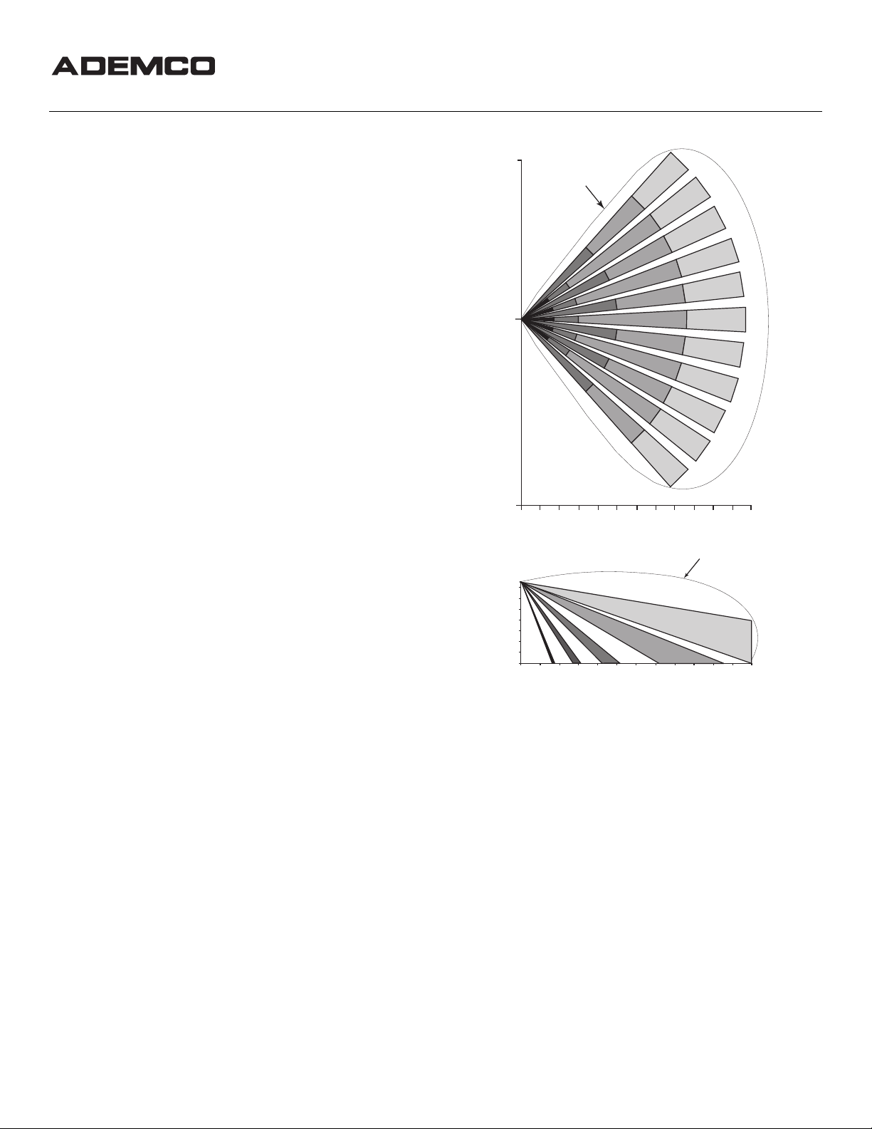
37.5'
(11.5 m)
0
MICROWAVE
PATTERN
SPECIFICATIONS
Detection Method: Dual-technology Microwave/PIR
Coverage: Standard Lens 60' x 75' (18.3m x 22.9m)
Detection Zones: Standard Lens: 38 zones (11 long range, 11
over 6 intermediate,5 over 5 short range, 1
Look-Down Zone)
Pulse Processing: Standard or Intermediate, selectable via a
DIP Switch
Detectable Walk Rate: 0.5-10 ft/sec (0.15-3m/sec)
Mounting Height: 7-8 ft (2.1-2.4m),
Indicator: Red and Green LED (see LED
INDICATIONS); enabled/disabled via
a DIP switch
Input Voltage: 9-13VDC at polling loop terminals with
reverse polarity protection
Current: 3mA nom. (Conditional Microwave mode)
6mA nom. (Normal mode), with LED
disabled
8mA nom. (alarm, with LED enabled)
Up to 8mA nominal during warm-up
Standby: Power source should be capable of at least
4 hours of battery standby
Operating Temp: -14°F to +122°F (-10°C to +50°C)
(0°C to +50°C for UL installations)
Operating Humidity: Up to 95% RH (max.), non-condensing
Dimensions: 2.8"W x 5.2"H x 2.2"D
(71mm x 132mm x 56mm)
COVERAGE & LOCATION CONSIDERATIONS
Combined protective patterns are shown in Figure 1 for a nominal
mounting height of 7.5 ft (2.3m). The microwave detection pattern
shown in Figure 1 represents coverage in open space. In practical
application, when the detector is bounded by ceiling, floor, and
walls, reflections can occur.
SELECTING A MOUNTING LOCATION
The detector responds to changes in energy that occur when an
intruder moves into the combined protection pattern. Best coverage
will be obtained if the mounting site is selected so that the likely
direction of intruder motion is generally across the pattern and
angle s slight ly towar d the detector.
37.5'
(11.5 m)
7.5' (2.3m)
7' (2.1m)
6' (1.8m)
5' (1.5m)
4' (1.2m)
3' (1.0m)
2' (0.6m)
1' (0.3m)
5'
0
10'
(1.5m)
(3m)
(4.5m)
5'
10'
0
(1.5m)
(3m)
(4.5m)
25'
30'
35'
15'
20'
(7.5m)
(6m)
TOP VIEW
25'
15'
20'
(7.5m)
(6m)
SIDE VIEW
(9m)
(9m)
(10.5)
30'
35'
(10.5)
40'
50'
45'
(12m)
(15m)
(13.5)
MICROWAVE PATTERN
40'
50'
45'
(12m)
(15m)
(13.5)
55'
(16.5)
55'
(16.5)
60'
(18m)
60'
(18m)
2260SN-001-V0
INSTALLATION HINTS
The detector is remarkably resistant to false alarm hazards, but the
following recommendations should be observed.
Never install the detector in an environment that causes a
•
disturbance in one technology. Good installations start with both
LEDs OFF when in the Accu-Trak environmental test mode and there
is no target motion.
Do not mount on an unstable surface. Locate the unit on a sturdy
•
inside wall whenever possible. Avoid sources of vibration such as loose
fitting doors and walls that shake when heavy traffic exists.
Do not install on or close to metal structures such as metal door
•
frames, shelves, etc.
Do not include space heaters in the protective pattern whenever
•
possible, to avoid rapid temperature changes and vibrations from
fans.
ALL microwave transmission penetrates most building materials
•
(except metal, which reflects transmission). Moving objects outside of
the protected area may be detected unless the microwave sensitivity
control is kept at as low a setting as possible, to minimize penetration.
Make sure the detection area does not have obstructions (curtains,
•
screens, large pieces of furniture, plants, etc.) that may block the PIR
portion of the coverage pattern.
MOUNTING
LENS HOLDER ASSEMBLY
(REMOVE FOR ACESS
tO LENS)
HOLDING T ABS
(2 EACH SIDE)
BEND INWARD TO
RELEASE LENS
HOLDER
LENS
(BEHIND LENS
HOLDER ASSEMBLY)
2260SN-004-V0
0
4
PCB SHOWN POSITIONED
FOR A SETTING OF "1"
PCB
SCREW
SCALE
0-4
USE AS
MARKER
2260SN-005-V0
Mount the unit to a firm vertical surface. The wall wiring hole
should be no more than 5/16" (8mm) diameter.
1. Remove the front cover by twisting a screwdriver blade in the
groove between cover and base at the bottom edge of the case
and then lifting the cover off.
2. Remove the circuit board: Loosen (do not remove) the vertical
adjustment screw, slide the PC board down, then spread the
PCB holding tabs (see Figure 3), and remove the PC board.
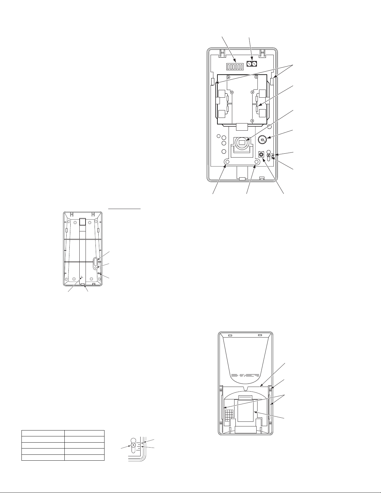
3. Break out desired mounting and wire entry holes in the back
case. Refer to Figure 2. Knockout screw holes “A” in the back
case are for normal surface mounting on a wall. Knockout screw
holes “B” are for corner mounting.
Also break out the wire entry hole marked X in Figure 2. If
surface wiring is to be used, break out the section at the bottom
of the back case, and run the wiring up the wiring channel at
the back of the case to hole “X”.
If the back case tamper is to be used, use an additional screw
through hole C to secure the back case to the mounting surface.
4. Feed wiring (unpowered) coming from the wall through the wire
access hole near the top of the detector case back. If surface
wiring is used, use bottom access hole and use the wiring
channel in the case ba ck for routin g the wires.
5. Mount the base and reinstall the PC board.
6. Vertically align the PC board in accordance with Table 1
(Vertical Pattern Adjustment section below) before
tightening the vertical adjustment screw.
7. Refer to WIRING CONNECTIONS section before replacing cover.
X
B
A
A
C
A
A
B
WIRING
CHANNEL
BREAK - OUT
SECTION (BEHIND)
FOR SURFACE
WIRING
BREAK - OUT HOLES
"A" FOR NORMAL SURFACE
MOUNTING (4)
"B" FOR CORNER
MOUNTING (4)
B
"C" SCREW HOLE FOR BACK
CASE TAMPER
"X" FOR WIRING ENTRY
ACTS AS BACK CASE
TAMPER
AFTER MOUNTING, USE
ADDITIONAL SCREW
HERE FOR TAMPER
B
USED TO SECURE
PC BOARD
(DO NOT REMOVE)
2260SN-002-VO
Figure 2. CASE BACK
WIRING CONNECTIONS
All wires shou ld have been fed thro ugh the wire access s lot at the
top of the detector base near the terminal block. Connect polling
loop wiring to the screw terminals as shown in Figure 3. Seal any
openings in the base with foam or RTV (not supplied) to prevent
drafts and insects from enteri ng t he un i t. Apply power only aft er all
connections have been made and are inspected.
DIP
SWITCH
POLLING
LOOP
CIRCUIT BOARD
HOLDING T ABS
(BEND OUTWARD TO
RELEASE BOARD)
1 2 3 4 5 6
12
+-
MICROWAVE
DETECTOR
PIR
DETECTOR
MICROWAVE SENSITIVITY
(TURN CLOCKWISE TO
INCREASE SENSITIVITY)
MIN MAX
0
4
MARKER
PCB SCREW
(LOOSEN TO CHANGE
VERTICAL PATTERN
USING SCALE AT RIGHT)
RED
LED
GREEN
LED
FRONT COVER
TAMPER SWITCH
2260SN-003-V1
Figure 3. INTERIOR OF DETECTOR
HORIZONTAL PATTERN ADJUSTMENT
The protection pattern can be moved to the left or right by horizontal
adjustment of the lens, as follows.
1. Remove the front cover as indicated in step 1 of the MOUNTING
section.
2. Remove the lens holder in the front cover by squeezing the two outer
sides of the holder together, releasing it from the side clips (see
Figure 4). Then pull the holder out, exposing the lens.
3. Slide the lens slightly to the left or right to change the horizontal
pattern as desired.
4. Reinstall the lens holder. It should snap firmly in place beneath the
holding tabs on each side.
5. Replace the front cover.
IMPORTANT: After any adjustment, conduct a walk test to ensure
proper coverage of the area to be protected. See the
Test Procedures section.
VERTICAL PATTERN ADJUSTMENT
The protection pattern can be moved up or down by vertical
adjustment of the lens as follows.
1. Remove the front cover as indicated in step 1 of the
MOUNTING section.
2. Loosen the PCB screw on the lower right of the board (s ee Fig.
3), and slide the board into the appropriate position, using the
scale to the right of the screw. Use Table 1 which shows the
proper setting for the de s ired range.
Table 1. Vertical Adjustment Settings
Desired Range PCB Position
30 ft (9.1m) position 4
40 ft (12.2m) posit i on 2
50 ft (15.2m) posit i on 1
60 ft (18.3m) posit i on 0
– 2 –
Figure 4. ACCESSING THE LENS

ADJUSTMEN TS AND SELECTIONS
Microwave Sensitivity Control
Turn the potentiometer clockwise to increase sensitivity.
DIP Switch Setti ngs
No. Position Function and Explanation
1 Supervision Failure Mode
ON: SUSPEND PIR: In case of microwave channel failure,
OFF (default): REVERT TO PIR: In case of microwave channel failure,
2 Fluorescent F ilter Mode
ON: 50Hz FLTR: Digital fluorescent light filter set for 50Hz.
OFF (default): 60Hz FLTR: Digital fluorescent light filter set for 60Hz.
3 LED Enable/Disable
ON (default): ENABLE: LEDs are enabled.
OFF: DISABLE: LEDs are disabled.
4Microwave Operation Mode
ON (default): NORMAL: Microwave channel always on.
OFF: CONDITIONAL: Microwave channel on only when PIR
5 Signal Processing Mode
ON: INTERMEDIATE: Use this setting in normal
OFF (default): STANDARD: Use this setting for maximum false alarm
6 Accu-Trak Environmental Test Mode
ON: ENV TEST: Accu-Trak environmental test is enabled.
OFF (default): NORMAL: Accu-Trak environmental test is disabled.
LED INDICATIONS
(use a small pointed tool to move the switch handle)
the unit becomes non-operat ional.
the unit reverts to the PIR only mode.
activity is detected.
environments.
immunity. This setting tolerates environmental
extremes and is the recommended setting.
(when LEDs are enabled)
MODE LED INDICATIONS
Power Up Red LED is ON for 30 seconds
Alarm Red LED ON
Accu-Trak Green LED flashes for microwave detection
Test Mode Red LED flashes for PIR detection
Supervision Red LED flashes for PIR failure once per 3 sec.
Failure Green LED flashes for microwave failure once per 3 sec.
SERIAL No. ID
This unit does not utilize DIP switches to set its zone number (ID).
Each unit has a unique factory-assigned serial number which must
be entered into the control panel during the zone programming
procedure. Therefore, this motion sensor can be used only with a
control that supports serial number devices.
Note that this motion sensor’s unique factory-assigned serial
number can be found on the bar code label on its PC board.
The motion sensor’s serial number can be entered by one of the
following methods:
A. Downloading (Zone Definition screen of Compass software).
Recommended for large installations and installations where
foot traffic cannot be controlled.
B. Entering through the keypad at the “INPUT S/N” prompt
during manual zone programmin g (see Impor t ant note below).
C. Activating the detector twice while at the “INPUT S/N” prompt
during manual zone programming.
If entering manually, be sure that other polling loop sensors are not
activated so that they cannot send a signal to the control while this
motion sensor is being programmed (mask motion sensors, don't
open/close doors, etc.).
To be sure that other polling loop devices are not activated when
entering serial numbers manually, power the system down,
disconnect the polling loop at the control, power back up again, and
immediately enter the program mode. Then proceed to Step 1 in the
following section. Remember to reconnect the polling loop when
programming is complete, powering the system down first.
IMPORTANT
To enter the unit's serial number
1. Using the control panel’s keypad, enter Zone Programming mode.
2. Enter t he Zone number, Zone Ty pe, and other zo ne information for
the motion sensor, pressing [∗] to advance from prompt to prompt.
3. At the "Input Type" prompt, enter "6" for SL (Serial Polling Device)
and press [∗].
4. At the “INPUT S/N” prompt, either enter the serial number manually
(and a "1" for the loop number), or fault the motion sensor (the keypad
will "beep" to confirm signal), then wait 3-6 seconds and fault the
motion sensor again (the keypad should beep again to confirm). The
motion sensor should now be enrolled. A "1" should appear under the
"L" on the zone summary screen. If it does not, press [∗] and enter the
loop number manually at the next screen.
5. Press [∗] to continue programming other devices, or enter “00” to quit.
For detailed information, refer to the Zone Programming section in the
control panel’s Installation Instructions.
TAMPER
Removal of the cover causes a front cover tamper switch to open.
Removal of the detector from the wall caus es the back tamper s witch to
open (if back case is tampered using a screw through the tamper hole;
see Figure 2). The control panel is automatically notified via the polling
loop when either of these events occur.
TEST PROCEDURES
On power-up, testing must not begin until the LED extinguishes after
first applying power to signify warm-up is complete, about 30 seconds. If
the LED begins to flash at a constant rate, refer to the section on
SUPERVISION.
Accu-Trak Environmental Test Mode
ADEMCO’s unique Accu-Trak environmental test feature easily provides
an environmental check for potential false alarm sources on both the
PIR and microwave channels. Simply set DIP Switch #6 to ON.
Both microwave and PIR information are viewable simultaneously on
the two LEDs, providing crisp, immediate feedback (see below).
NOTE: When Accu-T rak environmental test mode is selected, an
alarm signal is reported to the control panel to prevent leaving
the detector in the test mode.
TEST L ED ACCU-TRAK LED INDICATIONS
PIR RED LED flashes when potential false alarm source is
detected, such as fans or heating duct.
Microwave GREEN LED is ON when potential false alarm source is
detected, such as a fan or mylar balloon.
IMPORTANT:
Detection coverage can only be verified by walk-testing in the normal
operating mode (DIP Switch #6 set to OFF).
Testing in Normal Operating Mode
After testing with the unique Walk-Test mode, the detector should be
tested in the Normal Operating Mode with the following steps:
1. Remove the front cover and ensure that DIP Switch #6 is set to OFF
for Normal Operating Mode.
2. Set DIP Switch #5 to the Pulse Processing Option that will be used for
this installation.
3. Enable the LED by setting DIP Switch #3 ON.
4. Replace the front cover and walk through the protective zones,
observing that the detector’s red LED lights whenever motion is
detected. If necessary, re-adjust the microwave sensitivity to the
minimum level required for satisfactory detection and repeat the
Walk Test.
5. After Walk-Testing is complete, the LED may be disabled, if desired
(DIP Switch #3 OFF).
– 3 –

SUPERVISION
This motion sensor is equipped with advanced supervision of both
the PIR and microwave channels. If a microwave channel failure
occurs, the sensor will continue to operate as a dual-element PIR
sensor (when DIP switch #1 is set to ON) in Standard Signal
Processing mode regardless of the processing option chosen. Even
though some operation is maintained, the unit should be replaced
as soon as possible. If a PIR failure occurs, the unit becomes nonoperational.
Supervision Failure Indications
If a supervision failure occurs, it will be indicated by the
appropriate LED flashing once every 3 seconds, provided the LED
enable option was chosen by DIP switch #3. If a PIR failure occurs,
the RED LED will flash; if a microwave failure occurs, the GREEN
LED will flash. If the unit has defaulted to PIR-only operation as a
result of a microwave failure (DIP switch #1 is set to ON), the RED
LED will light when an alarm occurs while the GREEN LED
continues to flash.
All troubles above will be reported to the control panel.
MAINTAINING PROPER OPERATION
In order to maintain the detector in proper working condition, it is
important that the user observe the following:
1. Power should be provided at all times. Loss of power to the unit
will result in the alarm contacts reverting to an alarm state.
The units DC source should have standby power available for at
least 4 hours of operation during emergencies.
2. Units should never be re-aimed or relocated without the advice
or assistance of the alarm service company.
3. The physical surroundings of the protected area should not be
changed. If furniture or stock is moved, or air conditioning or
additional heating is installed, the system may have to be
readjusted by the alarm service company.
4. Walk tests should be conducted frequently (at least weekly) to
confirm proper coverage by each detector.
TO THE INSTALLER
Regular maintenance and inspection (at least annually) by the
installer and frequent testing by the user are vital to continuous
satisfactory operation of any alarm system.
The installer should assume the responsibility of developing and
offering a regular maintenance program to the user, as well as
acquainting the user with the proper operation and limitations of
the alarm system and its component parts.
Recommendations must be included for a specific program of
freque nt testing (at least we ekly) to ens ure the sys tem’s ope ration
at all times.
FEDERAL COMMUNICATIONS COMMISSION
(FCC) STATEMENT
This device complies with Part 15 of FCC Rules. Operation is
subject to the following two conditions:
(1) This device may not cause harmful interference, and
(2) This device must accept any interference received, including
interference that may cause undesired operation.
165 Eileen Way, Syosset, New York 11791
Copyright © 2000 PITTWAY CORPORATION
MICROWAVE/PASSlVE INFRARED MOTION DETECTOR
WARNING! THE LIMITATIONS OF YOUR
While the Intrusion Detector is a highly reliable intrusion detection device, it does not
offer guaranteed protection against burglary. Any Intrusion Detection device is
subject to compromise or failure to warn for a variety of reasons:
•
These Motion Detectors can only detect intr usion within the designed ra nges as
diagrammed in this install ation manual.
•
The passive infrared motion sensor in this Motion Detector does not provide
volumetric area protection. It does create multiple beams of protection, and
intrusion can only be detected in unobstructed areas covered by those beams.
•
Passive Infrared Detectors cannot detect motion or intrusion that takes place
behind walls, ceilings, floors, closed doors, glass partitions, glass doors, or
windows.
•
Metal objects (or other reflectors, such as foil faced insulation or water in bottles)
can alter the microwave sensors protection pattern.
•
Mechanical tampering, masking, painting or spraying of any material on the
mirrors, windows or any part of the optical system can reduce the detection ability
of the Passive Infrared Motion Detector.
•
Passive Infrared Detectors sense changes in temperat ure; however, as the am bie nt
temperature of the protected area approaches the temperature range of 90° to
105°F (32° to 40°C), the detection performance can decrease.
•
This Passive Infrared Detector will not operate without appropriate DC power
connected to it or if the DC power is improperly connected (i.e. reversed polarity
connections).
•
Passive Infrared Detectors, like other elect rical devices, are subject to component
failure. Even though they are designed to last as long as 10 years, t he electronic
components could fail at any time.
We have cited some of the most common reasons that a Passive Infrared Motion
Detector can fail to catch intrusion. However, this does not im ply that these are the
only reasons and therefore, it is recom me nded that wee kly test ing of this type of unit,
in conjunction with weekly testing of the entire alarm system, be performed to ensure
that the detectors are working properly.
Installing an alarm system may make the ow ner eligible for a lower insuran ce rate,
but an alarm system is not a substitut e for insurance. Hom eowners, pro perty owners
and renters should continue to act prudently i n pr ot ecting themsel ves an d co ntin ue to
insure their lives and property.
We continue to develop new and improved protection devices. Users of al arm systems
owe it to themselves and their loved ones to learn about these developments.
ADEMCO Limited Warranty
Alarm Device Manufact uring Company, a Division of Pittway Corporation, and its
divisions, subsidiar ies and affiliates ("Seller"), 165 Eilee n Way, Syosset, New York
11791, warrants this detector to be in conformance with its own plans and
specifications and to be free from defects in materials and workmanship under
normal use and service for 36 months from the d ate stamp control on the product.
Seller's obligation shall be limited to replacing, at its option, free of charge for
materials or labor, a detector which is proved not in compliance with Seller's
specifications or proves defective in materi als or workm anship under normal use an d
service. Seller shall have no obligation under t his Limited Warranty or otherwise if
the detector is altered or improperly repaired or serviced by anyone other than
Ademco factory service. In case of defect, return the detector to ADI or an authorized
distributor for an immediate replacement.
THERE ARE NO WARRANTIES, EXPRESS OR IMPLIED, OF
MERCHANTABILITY, OR FITNESS FOR A PARTICULAR PURPOSE OR
OTHERWISE, WHICH EXTEND BEYOND THE DESCRIPTION ON THE FACE
HEREOF. IN NO CASE SHALL SELLER BE LIABLE TO ANYONE FOR ANY
CONSEQUENTIAL OR INCIDENTAL DAMAGES FOR BREACH OF THIS OR ANY
OTHER WARRANTY, EXPRESS OR IMPLIED, OR UPON ANY OTHER BASIS OF
LIABILITY WHATSOEVER, EVEN IF THE LOSS OR DAMAGE IS CA USED BY
THE SELLER'S OWN NEGLIGENCE OR FAULT.
Seller does not represent that its detector may not be compromised or circumvented;
that the detector will prevent any personal injury or property loss by burglary,
robbery, fire or otherwise; or that the detector will in all cases provide adequate
warning or protection. Buyer u nderstands th at a properly installed and maintained
alarm may only reduce the risk of a burglary, robbery, fire or other events occurring
without providing an alar m, but it is not insuranc e or a guara ntee that such will not
occur or that there will be no personal injury or property loss as a result.
CONSEQUENTLY, SELLER SHALL HAVE NO LIABILITY FOR ANY PERSONAL
INJURY, PROPERTY DAMAGE OR OTHER LOSS BASED ON A CLAIM THE
DETECTOR FAILED TO GIVE WARNING. However, if Seller is held liable, whether
directly or indirectly, for any loss or damage arising under this Limited Warranty or
otherwise, regardless of ca use or origin, Seller's maximum lia bility shall not in any
case exceed the purchase price of the DET ECTOR, which sh all be the com plete and
exclusive remedy against Seller. This warranty replaces any previous warranties and
is the only warranty made by Seller on this detector. No increase or alteration,
written or verbal, of the obligations of this Limited Warranty is authorized.
¬.^l
K5510 12/00
 Loading...