

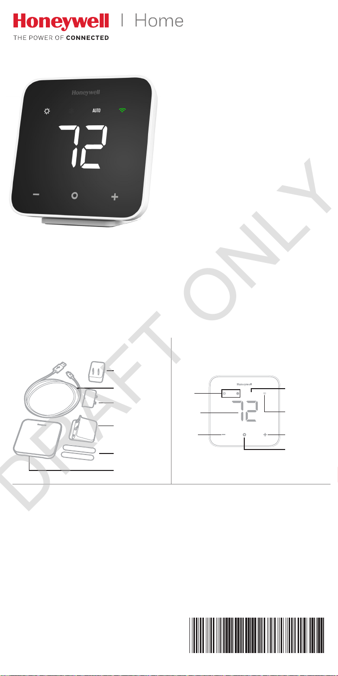
D6 PRO Wi-Fi
33-00322-01
DRAFT ONLY
DUCTLESS
CONTROLLER
Installation
Guide
For more information visit
yourhome.honeywell.com
In this box
Wall plug
USB cable
Back plate
Tabletop stand
Wall mount
adhesive
strips (2)
Controller
Quick reference
Mode
icons
Status
display
Down
button
AUTO
Auto
Changeover
WiFi status
Up button
Mode/
Select
button
Need Help?
Web
yourhome.honeywell.com
Email
MyLyric@honeywell.com
Phone
1-8 00 -6 33 -39 91
Home and Building Technologies
715 Peachtree Street NE
Atlanta, GA 30308
yourhome.honeywell.com
® U.S. Registered Trademark
© 2017 Honeywell International Inc.
33-00322—01 M.S. 12-17
Printed in U.S.A.
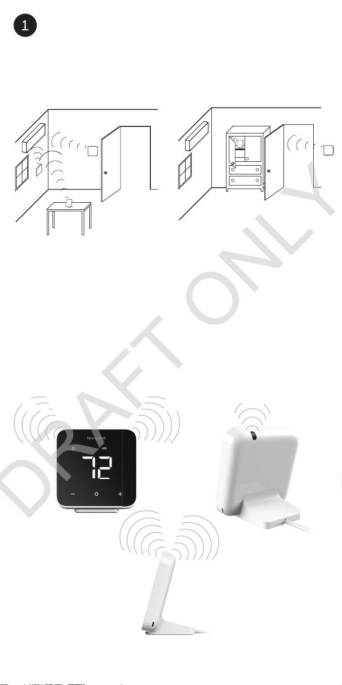
Choose a location
150°
)
(1
0°
)
°
)
DRAFT ONLY
Choose a location where the controller’s signal has a clear path to
the ductless unit.
Remove the batteries from the remote controller that came with the
ductless unit. That way the two controllers won’t send conflicting
commands.
r
ü
The controller sends an IR signal from three places. One on each side,
left and right, and one from the top.
Consider them when you choose a location.
75
5
0 ft (10 m
0 ft
0 m
30 ft (10 m
2
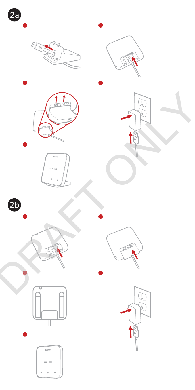
Tabletop assembly
DRAFT ONLY
1
Pull the power cord through
the tabletop stand.
2
Plug the power cord into the
controller.
3
Connect the tabletop stand to
the controller.
Place the controller in your
5
selected location.
Wall mount assembly
1
Plug the power cord into the
controller.
4
Plug the power cord into the wall
adapter, and plug in the wall adapter.
2
Snap the back plate onto the
controller.
3
Attach the wall mount adhesive
strips to the controller.
Attach the controller to the
5
wall in your selected location.
4
Plug the power cord into the wall
adapter, and plug in the wall adapter.
3
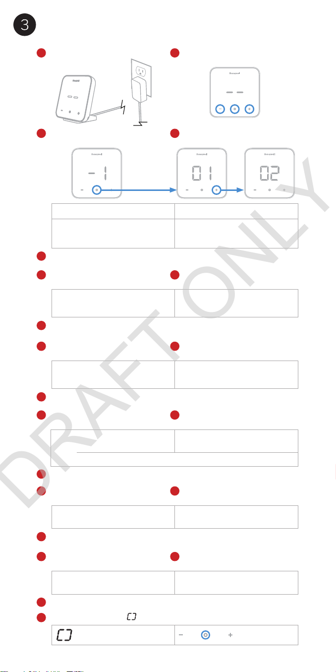
System setup
DRAFT ONLY
Connect the controller to power. Press any button to enter setup.
1
3a
Press
o to access options for
-1.
setting
Setting Options (Default in bold)
Controller Location 01 – Tabletop
-1
3c
Press
o to select the option for setting -1.
4a
Setting
-2 is displayed. Press o
to access options for setting
Temperature Scale 01 – °F
-2
o to select the option for setting -2.
Press
4c
-2.
2
3b
Press
to change setting -1 to
+
the desired option.
02 – Wall mount
4b
02 – °C
to change setting -2 to
Press
+
the desired option.
5a
5c
6a
6c
7a
7c
8a
8c
9
-3 is displayed. Press o
Setting
to access options for setting
Outdoor Unit
-3
Configuration
o to select the option for setting -3.
Press
-4 is displayed. Press o
Setting
to access options for setting
Multi Outdoor Unit
-4
Number*
*Only shown if Setting -3 is set to 02.
Press o to select the option for setting -4.
-5 is displayed. Press o
Setting
to access options for setting
Ductless Unit Brand See page 7 for Ductless Unit
-5
Press
o to select the option for setting -5.
Setting
-6 is displayed. Press o
to access options for setting
Ductless Unit Model See page 7 for Ductless Unit
-6
Press
o to select the option for setting -5.
The screen will display
Setup Complete
-3.
-4.
-5.
-6.
. Press o to save and exit system setup.
5b
01 – Single
02 – Multi
6b
02 - 99
7b
Brand ID
8b
Model ID
to change setting -3 to
Press
+
the desired option.
to change setting -4 to
Press
+
the desired option.
to change setting -5 to
Press
+
the desired option.
Press
to change setting -6 to
+
the desired option.
4
Idle mode
DRAFT ONLY
The controller goes into Idle mode (the screen is dim) after 45 seconds of
inactivity. Press any button to wake up the controller. The wake up button
push does not change temperature or settings.
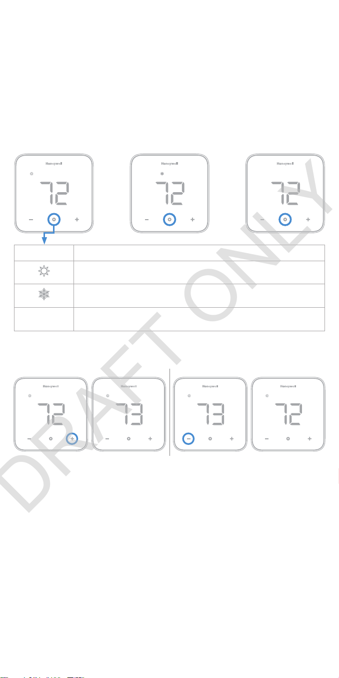
Change mode
1. Be sure the controller is not in Idle mode, then press
system mode.
2. Stop pressing
The ductless unit will beep when it gets a command from the controller.
Symbol Mode
[screen is
blank]
o when you reach the mode you want.
Heat mode - the ductless unit warms the space to the
temperature shown on the controller.
Cool mode - the ductless unit cools the space to the
temperature shown on the controller.
Off mode - the ductless unit is turned off
o to change the
Change temperature
Warmer Cooler
Room temperature
Any time the controller is not being interacted with, the current room
temperature is displayed on screen.
Viewing set temperature
Be sure the controller is not in Idle mode, then press + or - once to view
the current set temperature. The set temperature will “pulse” on screen.
After a short period of time the screen will change to display the room
temperature.
Change temperature
1. Be sure the controller is not in Idle mode, then press + or - more
than once to change the set temperature so it is higher or lower in the
current mode.
2. Stop pressing
3. The screen will pulse and then return to the room temperature
display.
or - when you reach the temperature you want.
+
5

Wi-Fi setup
AUTO
DRAFT ONLY
1. Download the Honeywell Home app.
2. Create an account or log in to your
account.
3. Select “Add new device” in the app.
4. Choose D6 Pro WiFi Ductless Controller.
5. Follow instructions in the app to configure the controller.
Note: During setup, the WiFi icon
you the controller status in the WiFi connection process.
Blinking blue Controller is powered up and ready to begin connecting.
Solid blue Controller is connected to the mobile device through the app.
Solid green Controller is connected to the WiFi network.
Solid red Controller is disconnected from the WiFi network.
Blinking red Controller is disconnected from WiFi network and has lost it’s
schedule. Reconnect to WiFi network to resume schedule.
will blink or be on solid. This tells
In the Honeywell Home app
In the app you can set the controller to Auto Changeover. The
controller will switch from heating mode to cooling mode based on the
temperature setting and the room temperature.
When in Auto Changeover mode,
screen.
will be displayed on the controller
GET IT ON
Enter system setup
You can change your controller settings at any time. To enter system
setup:
1. Be sure the controller is not in Idle mode, then press and hold
and o and - for three seconds all at the same time.
+
2. Change the settings as needed. See “System setup” for more
information.
Software and security questions,
Q: How can I be sure my thermostat is running the most up-to-date
firmware?
A: When your thermostat is connected to WiFi, it will automatically
receive over-the-air firmware updates from Honeywell. These firmware
updates contain things such as new features as well as security
upgrades. Keep your thermostat connected to WiFi to ensure it
receives these updates.
Q: How can I prevent a cybercriminal from making unauthorized changes
to my thermostat?
A: If a cybercriminal gains access to your WiFi router, they can tamper
with a wide range of online activities, including the settings on your
connected devices. Make sure you change the default password on
your WiFi router, and when you select a new password, make sure it
uses multiple upper- and lower-case letters and special characters
6

Brand Id Model Id
DRAFT ONLY
Mitsubishi 1 MSZ-GL Series(1) 1
MSZ-GL Series(2) 2
MSZ-EF Series 3
MSZ-FH Series 4
MSZ-GE Series 5
MSZ-FE Series(1) 6
MSZ-FE Series(2) 7
Generic model 594,
MSZ-ZB09VC, MSZZB12VC, MSZ-ZC09VC,
MSZ-YC09VC-H1,
MSZ-YC19VC-H1, MSZYE09VA-H1
Generic model 393,
MSD-CB09VD-H1,
MSD-CB12VD-H1,
MSD-EC09VD-H1, MSDEC12VD-H1
MSZ-HD serise, MSZ-HW
serise, MSZ-HW401S-W,
MSZ-HW561S-W
Mitsubishi Mr. Slim(1) 11
Mitsubishi Mr. Slim(2) 12
Daikin 2 LV Series 1
FT Series 2
RXN Series/KE
Series(indoor)
RXL Series/19
Series(indoor), 20
Series(indoor)
FVXS Series(1) 5
FVXS Series(2) 6
FTXN-N Series(1) 7
FTXN-N Series(2) 8
FTKN-N Series 9
FTX-N Series 10
FTK-N Series 11
Generic model
366, FTWN25JV1,
FTWN35JV1
Fujitsu 3 RLS3 Series 1
RLFW1 Series(1) 2
RLFW1 Series(2) 3
RLS3H Series 4
RL2 Series 5
RLX 6
RULX 7
RULX 8
Brand Id Model Id
LG 4 LA-HYV Series 1
LS-HSV4 Series 2
LS-HEV1 Series 3
LS-HXV Series 4
LMN-HVT Series(1) 5
LMN-HVT Series(2) 6
Midea 5 Generic model 40,
8
9
10
3
4
12
FSA10M16, FSA13M16,
FSAV13M16,
FSAV19M16,
FWAC08M16,
FWAC10M16,
FWAC13M16,
FWAC19M16,
FWAD08M16,
FWAD10M16,
FWAD13M16,
FWAD19M16,
PCCA24GWCWD,
PCCA36GWCWD,
PCCA48GWCWD,
WE012GMFI15HLD/
WYE012GMFI15RL,
ZACS-07 HPN1, ZACS09 HPN1, ZACSI-09
HPN, ZACSI-12
HPN, ZACSI-18
HPN, ZACSI-24 HPN,
MSC-09HRDN1-S,
MSC-12HRDN1-S,
MSR1-12HRN1,
MSR1-18HRN1,
MWH-07HR3N1,
MWH-09HR3N1,
MWH-12HR3N1,
MWH-18HR3N1, CHC28V2H, CHI-28V2H,
CCS009CA, CCS009CA2B, CCS009CA-2BI,
CCS012CA, CCS012CA2B, CCS012CA-2BI,
CCS012CD, CCS012CD2B, CCS012CD2BI, CCS018CD,
CCS018CD-2BI,
CCS024CD, CCS024CD2BI, CHP009CA-2BI,
CHP012CA-2BI,
CHP012CD-2BI,
CHP018CD-2BI,
CHP024CD2BI, CHP030CDI,
CHP036CDI, MS25F1,
MS25VC3, MS25VCT,
RXI-232CM, KFIM12,
KTIM036-H2,
KTIM12U, KTIM18U,
KTIM24, KUIM036-H2,
KUIM048-H2,
KUIM12U, KUIM18U,
KUIM24, KFUF036-C2,
KFUF048-C2,
KFUF060-C2, MSE09CR
Generic model 579 2
Generic model 589 3
1
7

Brand Id Model Id
DRAFT ONLY
Midea 5 Generic model 46,
SAC-V22HE, HP12K,
HP18K, HP22K,
FRS123LS1, KSE26HRA,
DHM12N, DHM18N,
DHM24N, DHM30N,
DHM36N, 12000
BTU, A37GW2C-I2,
A55GW2C-I2,
A74GW2C-I2, CIH
SERIES, CIC SERIES,
SMA SERIES, VMH
SERIES, KSIL036-H215,
KSIN009-H115,
KSIN012-C115,
KSIN012-C215,
KSIN012-H115,
KSIN012-H215,
KSIN018-C215,
KSIN018-H215
Generic model 54,
MSE09M4
VMH09SDKIT25,
VMH09SDKIT50,
VMH12SDKIT25,
VMH12SDKIT50,
VMH18SDKIT25,
VMH18SDKIT50,
VMH24SDKIT25,
VMH24SDKIT50,
Generic model 55,
38/40MAQ, 38/40MBQ,
38GJQ/40GJ,
38MAQ/40MBC,
D Series Single
Zone, VMH Inverter
Series, DA1215-H1,
DA1815-H2,
DA2415-H2
Generic model 56,
Y8HJZC009BAMLAFX,
Y8HJZC012BAMLAFX,
Y8HJZC018BAMLAFX,
Y8HJZC021BAMLAFX,
Y8HJZC024BAMLAFX,
Y9HJZC018BAMLAFX,
Y9HJZC024BAMLAFX,
Y9HJZH009BAMLAFX,
Y9HJZH012BAMLAFX,
YPHJYH009
Heat Pump MA*D Ducted
Models, Heat Pump
MB*C Models, Heat
Pump MB*D Ducted
Models, Heat Pump
MB*F Models, Generic
model 512, AURA Series,
DA-INVERTER Series,
DVC Series, KSID012H115Q, KSID016H214Q, KSID022H215Q, KSID032H214Q, KSIO009-H124,
KSIO012-H123,
KSIO018-H221,
KSIO024-H219,
A-09-HP-C-230, A-12HP-C-230,
4
5
6
7
8
Brand Id Model Id
Midea 5 A-18-HP-C-230,
A-22-HP-C-230,
DIY-12-C-HP-115,
DIY-18-C-HP-230,
DIY-24-C-HP-230,
DIY-32-C-HP-230,
O-09HP-C-115,
O-12HP-C-115,
O-18HP-C-230,
O-24HP-C-230,
P-09HP-C-230,
P-12HP-C-230,
P-18HP-C-230,
P-24HP-C-230, Aura
serie
Generic model 972 9
Generic model 78, LETO
SERIES
Gree 6 Generic model 645,
38GRQ, 40GRQ, U铂2
代, U雅2代
Generic model 376 2
I-铂, I-雅, U-铂, U-雅, I酷, U-酷
Generic model 18,
Y502K, CSA120H,
EWA120H, GH-PAC-12,
GM-PAC-12
Generic model 292,
KC-R serise, WAC-307R,
WAC-309R, WAC-312R,
WAC-318R
Terra Ductless, Terra Mini
Split, B-VFH09MA-1,
B-VFH12MA-1,
B-VFH18MA-1,
InverterFlex? Series
Generic model 823 7
Generic model 1058,
A18EM4H4R18,
A18EM4H4R24,
A20EM4H4R12,
A22EM4H4R09,
38/40GVC, 38/40GVM,
38/40GVQ, 38/40GXM,
FRS184YS2,
FRS224YS2,
GSA08, GSA09,
GSA12, GSA209A,
GSA212A, GSA218A,
GSA224A, INVERTER,
BMKH09-15YN4GA,
BMKH09-22YN4GA,
BMKH12-15YN4GA,
BMKH12-20YN4GA,
BMKH18-15YN4GA,
BMKH18-18YN4GA,
BMKH24-15YN4GA
Generic model 15 9
Gree 6 ZAS1229A , ZAS1825A,
ZAS2429A, Z AS925A,
Generic model 429,
HW240C1, HW240E,
B-VFH09FA-1,
B-VFH12FA-1,
B-VFH18FA-1
8
8
10
1
3
4
5
6
8
10

Brand Id Model Id
DRAFT ONLY
Haier 7 Generic model 20002 1
ESAQ406P, ESAQ408P,
Generic model 417
Generic model 655 3
Generic model 830 4
A0010401314J,
A0010401511J,
AW07LC2VHA,
AW09LC2VHA,
AW12LC2VHA,
AW18LC2VHA,
HSU09VHG,
HSU09VHG(DB),
HSU09VHG(DB)-G,
HSU09VHG(DB)-W,
HSU09VHGDB,
HSU09VHGDBG,
HSU09VHGDB-G,
HSU09VHGDBW,
HSU09VHGDB-W,
HSU09XHK,
HSU09XHKG,
HSU09XHK-G,
HSU109VHG,
HSU109VHGG,
HSU109VHG-G,
HSU112VHG,
HSU112VHGG,
HSU112VHG-G,
HSU12HXKG,
HSU12HXK-G,
HSU12HXKW,
HSU12HXK-W,
HSU12VHG,
HSU12VHG(DB),
HSU12VHG(DB)-G,
HSU12VHG(DB)-W,
HSU12VHGDB,
HSU12VHGDBG,
HSU12VHGDB-G,
HSU12VHGDBW,
HSU12VHGDB-W,
HSU12XHK, HSU18VHG,
HSU18VHG(DB),
HSU18VHG(DB)-G,
HSU18VHG(DB)-W,
HSU18VHGDB,
HSU18VHGDBG,
HSU18VHGDB-G,
HSU18VHGDBW,
HSU18VHGDB-W,
HSU18VHK,
HSU18VHKG,
HSU18VHK-G,
HSU18VHKW,
HSU18VHK-W,
HSU24VHG,
HSU24VHG(DB),
HSU24VHG(DB)-G,
HSU24VHG(DB)-W,
Brand Id Model Id
Haier 7 HSU24VHGDB,
2
5
HISENSE 8 KFR-39BP, KFR-45LW 1
CHIGO 9 Generic model 640 1
HSU24VHGDBG,
HSU24VHGDB-G,
HSU24VHGDBW,
HSU24VHGDB-W,
HSU24VHK,
HSU24VHKG,
HSU24VHK-G,
HSU24VHKW,
HSU24VHK-W,
HVAC5620001, YRHD01
Generic model 1061 6
KF-50LW/01HBF12,
KF-50LW/02HBF13,
KF-72LW/01HBF12,
KF-72LW/01HBF13,
KFR-50LW/02HBF12,
KFR-50LW/02HBF13,
KFR-50LW/06HBF13,
KFR-72LW/02HBF12,
KFR-72LW/02HBF13,
KFR-72LW/06HBF13,
KFR-76LW/01HBF13
Generic model 256 8
Generic model 406 9
Generic model 836,
AC562016, HPAC9M,
HPM07XC5, AP075M,
AP093M, AP095R,
AP099R, AP125HD
Generic model 405 2
Generic model 9 3
Generic model 68 4
Generic model 410 5
Generic model 427 6
Generic model 10 7
Generic model 12 8
Generic model 80 9
KFR-35G 27FZBPHJ 10
YHJH-90A/E2GE,
Generic model 613
Generic model 5 3
Generic model 121 4
Generic model 122 5
Generic model 123 6
Generic model 124 7
Generic model 125 8
Generic model 126 9
Generic model 127 10
5
7
10
2
9

Brand Id Model Id
DRAFT ONLY
KELON 10 Generic model 12 1
Generic model 409 2
Generic model 411 3
Generic model 13 4
Generic model 14 5
Generic model 143 6
Generic model 485 7
Generic model 486 8
Generic model 487 9
Generic model 489 10
PANASONIC 11 Generic model 674,
CS-PA12DKD/bmJ,
CS-PA12GKD/bmJ,
CS-PA16EKD/bmJ,
CS-PA16GKD/bmJ,
CS-PA7DKD/bmJ,
CS-PA7GKD//bmJ,
CS-PA9DKD/bmJ,
CS-PA9GKD/bmJ,
CS-PW12KKA,
CS-PW9KKA
Generic model
673, CS-V12RWA,
CS-V12RWA-2,
CS-V9RWA, CS-V9RWA-2
Generic model 583 3
Generic model 323,
CS-S9MKA
Generic model 293 5
RB-S34HWM, Generic
model 211
Generic model 47,
CS-C10KC1/bmJ,
CS-C10P17KS/bmJ,
CS-C10P27KS/bmJ,
CS-C1208KW/bmJ,
CS-C1209KW/bmJ,
CS-C1217KW/bmJ,
CS-C1218KW/bmJ,
CS-C1227KW/bmJ,
CS-C1299KW/bmJ,
CS-C12B17KN/bmJ,
CS-C12B17KY/bmJ,
CS-C12KA1/bmJ,
CS-C12KB1/bmJ,
CS-C12KB2/bmJ,
CS-C12KC1/bmJ,
CS-C1308KW/bmJ,
CS-C1309KW/bmJ,
CS-C1317KW/bmJ,
CS-C1318KW/bmJ,
CS-C13B17KN/bmJ,
CS-C13B17KY/bmJ,
CS-C13KA1/bmJ,
CS-C13KB1/bmJ,
CS-C13KB2/bmJ,
CS-C15P17KS/bmJ,
CS-C1617KW/bmJ,
CS-C1618KW/bmJ,
CS-C16P17KS/bmJ,
CS-C2217KB/bmJ,
Brand Id Model Id
PANASONIC 11 CS-C2217KGM/bmJ,
1
2
4
6
7
CS-C2517KB/bmJ,
CS-C2517KGM/bmJ,
CS-C2527KB/bmJ,
CS-C2527KGM/bmJ,
CS-C3217KB/bmJ,
CS-C3217KGM/bmJ,
CS-C3617KB/bmJ,
CS-C3617KGM/bmJ,
CS-C708KW/bmJ,
CS-C709KW/bmJ,
CS-C717KW/bmJ,
CS-C718KW/bmJ,
CS-C7B17KN/bmJ,
CS-C7B17KY/bmJ,
CS-C7KA1/bmJ,
CS-C7KB1/bmJ,
CS-C7KB2/bmJ,
CS-C8P17KS/bmJ,
CS-C908KW/bmJ,
CS-C909KW/bmJ,
CS-C917KW/bmJ,
CS-C918KW/bmJ,
CS-C927KW/bmJ,
CS-C999KW/bmJ,
CS-C9B17KN/bmJ,
CS-C9B17KY/bmJ,
CS-C9B27KN/bmJ,
CS-C9B27KY/bmJ,
CS-C9KA1/bmJ,
CS-C9KA9/bmJ,
CS-C9KB1/bmJ,
CS-C9KB2/bmJ,
CS-HC10P08KS/bmJ,
CS-HC10P09KS/bmJ,
CS-HC1227KW/bmJ,
CS-HC12B08KY/bmJ,
CS-HC12B09KY/bmJ,
CS-HC12KA1B/bmJ,
CS-HC12KA1G/bmJ,
CS-HC12KA1L/bmJ,
CS-HC12KA1S/bmJ,
CS-HC15B08KY/bmJ,
CS-HC15B09KY/bmJ,
CS-HC15KA1L/bmJ,
CS-HC15P08KS/bmJ,
CS-HC15P09KS/bmJ,
CS-HC16P08KS/bmJ,
CS-HC18P08KS/bmJ,
CS-HC18P09KS/bmJ,
CS-HC2108KB/bmJ,
CS-HC2108KGM/bmJ,
CS-HC2109KB/bmJ,
CS-HC2109KGM/bmJ,
CS-HC2508KB/bmJ,
CS-HC2508KGM/bmJ,
CS-HC2509KB/bmJ,
CS-HC2509KGM/bmJ,
CS-HC3208KB/bmJ,
CS-HC3208KGM/bmJ,
CS-HC3209KB/bmJ,
CS-HC3209KGM/bmJ,
CS-HC4008KB/bmJ,
CS-HC4008KGM/bmJ,
CS-HC4009KB/bmJ,
CS-HC4009KGM/bmJ,
CS-HC7B08KY/bmJ,
CS-HC7B09KY/bmJ,
CS-HC7KA1B/bmJ,
CS-HC7KA1G/bmJ,
7
10

Brand Id Model Id
DRAFT ONLY
PANASONIC 11 CS-HC7KA1L/bmJ,
CS-HC7KA1S/bmJ,
CS-HC8P08KS/bmJ,
CS-HC8P09KS/bmJ,
CS-HC927KW/bmJ,
CS-HC9B08KY/bmJ,
CS-HC9B09KY/bmJ,
CS-HC9KA1B/bmJ,
CS-HC9KA1G/bmJ,
CS-HC9KA1L/bmJ,
CS-HC9KA1S/bmJ,
CS-JC10KC1/bmJ,
CS-JC10KC1N/bmJ,
CS-JC10KC1S/bmJ,
CS-JC12KB1/bmJ,
CS-JC12KC1/bmJ,
CS-JC12KC1N/bmJ,
CS-JC12KC1S/bmJ,
CS-JC15KB1/bmJ,
CS-JC7KB1/bmJ,
CS-JC7KC1/bmJ,
CS-JC7KC1N/bmJ,
CS-JC7KC1S/bmJ,
CS-JC9KB1/bmJ,
CS-PC1208KW/bmJ,
CS-PC1217KW/bmJ,
CS-PC12KC1/bmJ,
CS-PC1308KW/bmJ,
CS-PC1317KW/bmJ,
CS-PC13KC1/bmJ,
CS-PC908KW/bmJ,
CS-PC917KW/bmJ,
CS-PC9KC1/bmJ,
CS-SC1227KW/bmJ,
CS-SC708KW/bmJ,
CS-SC727KW/bmJ,
CS-SC7KB1/bmJ,
CS-SC908KW/bmJ,
CS-SC927KW/bmJ,
CS-SC9KB1/bmJ,
CS-SC9KB9/bmJ,
CZ-RL027DW/bmJ,
CZ-RL037DW/bmJ,
CS-A10KC1/bmJ,
CS-A10P17KS/bmJ,
CS-A10P17KT//bmJ,
CS-A1208KW/bmJ,
CS-A1209KW/bmJ,
CS-A1218KW/bmJ,
CS-A12B17KN/bmJ,
CS-A12B17KY/bmJ,
CS-A12B27KN/bmJ,
CS-A12B27KY/bmJ,
CS-A12KA1/bmJ,
CS-A12KB1/bmJ,
CS-A12KB2/bmJ,
CS-A1308KW/bmJ,
CS-A1309KW/bmJ,
CS-A1318KW/bmJ,
CS-A13B17KN/bmJ,
CS-A13B17KY/bmJ,
CS-A13KA1/bmJ,
CS-A13KA2/bmJ,
CS-A13KB1/bmJ,
CS-A13KB2,
CS-A13KC1/bmJ,
CS-A15P17KMZ/bmJ,
CS-A15P17KS/bmJ,
CS-A15P17KT//bmJ,
CS-A15P27KMZ/bmJ,
Brand Id Model Id
7
PANASONIC 11 CS-A15P27KT/bmJ,
CS-A1618KW/bmJ,
CS-A16P17KMZ/bmJ,
CS-A16P17KS/bmJ,
CS-A16P17KT/bmJ,
CS-A2217KB/bmJ,
CS-A2217KGM/bmJ,
CS-A2517KB/bmJ,
CS-A2517KGM/bmJ,
CS-A3617KB/bmJ,
CS-A3617KGM/bmJ,
CS-A708KW/bmJ,
CS-A709KW/bmJ,
CS-A718KW/bmJ,
CS-A7KA1/bmJ,
CS-A7KB1/bmJ,
CS-A7KB2/bmJ,
CS-A908KW/bmJ,
CS-A909KW/bmJ,
CS-A918KW/bmJ,
CS-A927KW/bmJ,
CS-A9KA1/bmJ,
CS-A9KB1/bmJ,
CS-A9KB2/bmJ,
CS-HA10P08KS/bmJ,
CS-HA10P09KS/bmJ,
CS-HA1227KW/bmJ,
CS-HA1258KW/bmJ,
CS-HA12B08KY/bmJ,
CS-HA12B09KY/bmJ,
CS-HA12KA1B/bmJ,
CS-HA12KA1G/bmJ,
CS-HA12KA1L/bmJ,
CS-HA12KA1S/bmJ,
CS-HA15B08KY/bmJ,
CS-HA15B09KY/bmJ,
CS-HA15KA1L/bmJ,
CS-HA15P08KS/bmJ,
CS-HA15P09KS/bmJ,
CS-HA16P08KS/bmJ,
CS-HA18P08KS/bmJ,
CS-HA18P09KS/bmJ,
CS-HA2108KB/bmJ,
CS-HA2108KGM/bmJ,
CS-HA2109KB/bmJ,
CS-HA2109KGM/bmJ,
CS-HA2608KB/bmJ,
CS-HA2608KGM/bmJ,
CS-HA2609KB/bmJ,
CS-HA2609KGM/bmJ,
CS-HA3208KB/bmJ,
CS-HA3208KGM/bmJ,
CS-HA3209KB/bmJ,
CS-HA3209KGM/bmJ,
CS-HA4008KB/bmJ,
CS-HA4008KGM/bmJ,
CS-HA4009KB/bmJ,
CS-HA4009KGM/bmJ,
CS-HA7B08KY/bmJ,
CS-HA7B09KY/bmJ,
CS-HA7KA1B/bmJ,
CS-HA7KA1G/bmJ,
CS-HA7KA1L/bmJ,
CS-HA7KA1S/bmJ,
CS-HA8P08KS/bmJ,
CS-HA8P09KS/bmJ,
CS-HA927KW/bmJ,
CS-HA958KW/bmJ,
CS-HA9B08KY/bmJ,
CS-HA9B09KY/bmJ,
7
11

Brand Id Model Id
DRAFT ONLY
PANASONIC 11 CS-HA9KA1B/bmJ,
CS-HA9KA1G/bmJ,
CS-HA9KA1L/bmJ,
CS-HA9KA1S/bmJ,
CS-JA10KC1/bmJ,
CS-JA10KC1N/bmJ,
CS-JA10KC1S/bmJ,
CS-JA12KB1/bmJ,
CS-JA12KC1/bmJ,
CS-JA12KC1N/bmJ,
CS-JA12KC1S/bmJ,
CS-JA13KC1/bmJ,
CS-JA13KC1N/bmJ,
CS-JA13KC1S/bmJ,
CS-JA15KB1/bmJ,
CS-JA7KB1/bmJ,
CS-JA7KC1/bmJ,
CS-JA7KC1N/bmJ,
CS-JA7KC1S/bmJ,
CS-JA9KB1/bmJ,
CS-NA13KB1/bmJ,
CS-NA15KB1/bmJ,
CS-PA10KC1/bmJ,
CS-PA1208KW/bmJ,
CS-PA1217KW/bmJ,
CS-PA12KC1/bmJ,
CS-PA1308KW/bmJ,
CS-PA1317KW/bmJ,
CS-PA13KC1/bmJ,
CS-PA908KW/bmJ,
CS-PA917KW/bmJ,
CS-SA1208KW/bmJ,
CS-SA1227KW/bmJ,
CS-SA12KB1/bmJ,
CS-SA13KA9/bmJ,
CS-SA13KB2/bmJ,
CS-SA13KB9/bmJ,
CS-SA708KW/bmJ,
CS-SA727KW/bmJ,
CS-SA7KB1/bmJ,
CS-SA908KW/bmJ,
CS-SA927KW/bmJ,
CS-SA9KB1/bmJ,
CZ-RL527DW/bmJ,
CZ-RL537DW/bmJ,
CS-PC1808FW/bmJ,
CS-PC2708FW/bmJ,
CS-PC2708FWYbmJ,
CS-PC4508FWY/bmJ
CS-C918KW/bmJ,
CS-C927KW/bmJ,
CS-C999KW/bmJ,
CS-C9B17KN/bmJ,
CS-C9B17KY/bmJ,
CS-C9B27KN/bmJ,
CS-C9B27KY/bmJ,
CS-C9KA1/bmJ,
CS-C9KA9/bmJ,
CS-C9KB1/bmJ,
CS-C9KB2/bmJ,
CS-HC10P08KS/bmJ,
CS-HC10P09KS/bmJ,
CS-HC1227KW/bmJ,
CS-HC12B08KY/bmJ,
CS-HC12B09KY/bmJ,
CS-HC12KA1B/bmJ,
CS-HC12KA1G/bmJ,
CS-HC12KA1L/bmJ,
CS-HC12KA1S/bmJ,
Brand Id Model Id
7
PANASONIC 11 CS-HC15B08KY/bmJ,
CS-HC15B09KY/bmJ,
CS-HC15KA1L/bmJ,
CS-HC15P08KS/bmJ,
CS-HC15P09KS/bmJ,
CS-HC16P08KS/bmJ,
CS-HC18P08KS/bmJ,
CS-HC18P09KS/bmJ,
CS-HC2108KB/bmJ,
CS-HC2108KGM/bmJ,
CS-HC2109KB/bmJ,
CS-HC2109KGM/bmJ,
CS-HC2508KB/bmJ,
CS-HC2508KGM/bmJ,
CS-HC2509KB/bmJ,
CS-HC2509KGM/bmJ,
CS-HC3208KB/bmJ,
CS-HC3208KGM/bmJ,
CS-HC3209KB/bmJ,
CS-HC3209KGM/bmJ,
CS-HC4008KB/bmJ,
CS-HC4008KGM/bmJ,
CS-HC4009KB/bmJ,
CS-HC4009KGM/bmJ,
CS-HC7B08KY/bmJ,
CS-HC7B09KY/bmJ,
CS-HC7KA1B/bmJ,
CS-HC7KA1G/bmJ,
CS-HC7KA1L/bmJ,
CS-HC7KA1S/bmJ,
CS-HC8P08KS/bmJ,
CS-HC8P09KS/bmJ,
CS-HC927KW/bmJ,
CS-HC9B08KY/bmJ,
CS-HC9B09KY/bmJ,
CS-HC9KA1B/bmJ,
CS-HC9KA1G/bmJ,
CS-HC9KA1L/bmJ,
CS-HC9KA1S/bmJ,
CS-JC10KC1/bmJ,
CS-JC10KC1N/bmJ,
CS-JC10KC1S/bmJ,
CS-JC12KB1/bmJ,
CS-JC12KC1/bmJ,
CS-JC12KC1N/bmJ,
CS-JC12KC1S/bmJ,
CS-JC15KB1/bmJ,
CS-JC7KB1/bmJ,
CS-JC7KC1/bmJ,
CS-JC7KC1N/bmJ,
CS-JC7KC1S/bmJ,
CS-JC9KB1/bmJ,
CS-PC1208KW/bmJ,
CS-PC1217KW/bmJ,
CS-PC12KC1/bmJ,
CS-PC1308KW/bmJ,
CS-PC1317KW/bmJ,
CS-PC13KC1/bmJ,
CS-PC908KW/bmJ,
CS-PC917KW/bmJ,
CS-PC9KC1/bmJ,
CS-SC1227KW/bmJ,
CS-SC708KW/bmJ,
CS-SC727KW/bmJ,
CS-SC7KB1/bmJ,
CS-SC908KW/bmJ,
CS-SC927KW/bmJ,
CS-SC9KB1/bmJ,
CS-SC9KB9/bmJ,
CZ-RL027DW/bmJ,
7
12

Brand Id Model Id
DRAFT ONLY
PANASONIC 11 CZ-RL037DW/bmJ,
CS-A10KC1/bmJ,
CS-A10P17KS/bmJ,
CS-A10P17KT//bmJ,
CS-A1208KW/bmJ,
CS-A1209KW/bmJ,
CS-A1218KW/bmJ,
CS-A12B17KN/bmJ,
CS-A12B17KY/bmJ,
CS-A12B27KN/bmJ,
CS-A12B27KY/bmJ,
CS-A12KA1/bmJ,
CS-A12KB1/bmJ,
CS-A12KB2/bmJ,
CS-A1308KW/bmJ,
CS-A1309KW/bmJ,
CS-A1318KW/bmJ,
CS-A13B17KN/bmJ,
CS-A13B17KY/bmJ,
CS-A13KA1/bmJ,
CS-A13KA2/bmJ,
CS-A13KB1/bmJ,
CS-A13KB2,
CS-A13KC1/bmJ,
CS-A15P17KMZ/bmJ,
CS-A15P17KS/bmJ,
CS-A15P17KT//bmJ,
CS-A15P27KMZ/bmJ,
CS-A15P27KS/bmJ,
CS-A15P27KT/bmJ,
CS-A1618KW/bmJ,
CS-A16P17KMZ/bmJ,
CS-A16P17KS/bmJ,
CS-A16P17KT/bmJ,
CS-A2217KB/bmJ,
CS-A2217KGM/bmJ,
CS-A2517KB/bmJ,
CS-A2517KGM/bmJ,
CS-A3617KB/bmJ,
CS-A3617KGM/bmJ,
CS-A708KW/bmJ,
CS-A709KW/bmJ,
CS-A718KW/bmJ,
CS-A7KA1/bmJ,
CS-A7KB1/bmJ,
CS-A7KB2/bmJ,
CS-A908KW/bmJ,
CS-A909KW/bmJ,
CS-A918KW/bmJ,
CS-A927KW/bmJ,
CS-A9KA1/bmJ,
CS-A9KB1/bmJ,
CS-A9KB2/bmJ,
CS-HA10P08KS/bmJ,
CS-HA10P09KS/bmJ,
CS-HA1227KW/bmJ,
CS-HA1258KW/bmJ,
CS-HA12B08KY/bmJ,
CS-HA12B09KY/bmJ,
CS-HA12KA1B/bmJ,
CS-HA12KA1G/bmJ,
CS-HA12KA1L/bmJ,
CS-HA12KA1S/bmJ,
CS-HA15B08KY/bmJ,
CS-HA15B09KY/bmJ,
CS-HA15KA1L/bmJ,
CS-HA15P08KS/bmJ,
CS-HA15P09KS/bmJ,
CS-HA16P08KS/bmJ,
CS-HA18P08KS/bmJ,
Brand Id Model Id
7
PANASONIC 11 CS-HA18P09KS/bmJ,
CS-HA2108KB/bmJ,
CS-HA2108KGM/bmJ,
CS-HA2109KB/bmJ,
CS-HA2109KGM/bmJ,
CS-HA2608KB/bmJ,
CS-HA2608KGM/bmJ,
CS-HA2609KB/bmJ,
CS-HA2609KGM/bmJ,
CS-HA3208KB/bmJ,
CS-HA3208KGM/bmJ,
CS-HA3209KB/bmJ,
CS-HA3209KGM/bmJ,
CS-HA4008KB/bmJ,
CS-HA4008KGM/bmJ,
CS-HA4009KB/bmJ,
CS-HA4009KGM/bmJ,
CS-HA7B08KY/bmJ,
CS-HA7B09KY/bmJ,
CS-HA7KA1B/bmJ,
CS-HA7KA1G/bmJ,
CS-HA7KA1L/bmJ,
CS-HA7KA1S/bmJ,
CS-HA8P08KS/bmJ,
CS-HA8P09KS/bmJ,
CS-HA927KW/bmJ,
CS-HA958KW/bmJ,
CS-HA9B08KY/bmJ,
CS-HA9B09KY/bmJ,
CS-HA9KA1B/bmJ,
CS-HA9KA1G/bmJ,
CS-HA9KA1L/bmJ,
CS-HA9KA1S/bmJ,
CS-JA10KC1/bmJ,
CS-JA10KC1N/bmJ,
CS-JA10KC1S/bmJ,
CS-JA12KB1/bmJ,
CS-JA12KC1/bmJ,
CS-JA12KC1N/bmJ,
CS-JA12KC1S/bmJ,
CS-JA13KC1/bmJ,
CS-JA13KC1N/bmJ,
CS-JA13KC1S/bmJ,
CS-JA15KB1/bmJ,
CS-JA7KB1/bmJ,
CS-JA7KC1/bmJ,
CS-JA7KC1N/bmJ,
CS-JA7KC1S/bmJ,
CS-JA9KB1/bmJ,
CS-NA13KB1/bmJ,
CS-NA15KB1/bmJ,
CS-PA10KC1/bmJ,
CS-PA1208KW/bmJ,
CS-PA1217KW/bmJ,
CS-PA12KC1/bmJ,
CS-PA1308KW/bmJ,
CS-PA1317KW/bmJ,
CS-PA13KC1/bmJ,
CS-PA908KW/bmJ,
CS-PA917KW/bmJ,
CS-SA1208KW/bmJ,
CS-SA1227KW/bmJ,
CS-SA12KB1/bmJ,
CS-SA13KA9/bmJ,
CS-SA13KB2/bmJ,
CS-SA13KB9/bmJ,
CS-SA708KW/bmJ,
CS-SA727KW/bmJ,
CS-SA7KB1/bmJ,
CS-SA908KW/bmJ,
7
13

Brand Id Model Id
DRAFT ONLY
PANASONIC 11 CS-SA927KW/bmJ,
CS-SA9KB1/bmJ,
CZ-RL527DW/bmJ,
CZ-RL537DW/bmJ,
CS-PC1808FW/bmJ,
CS-PC2708FW/bmJ,
CS-PC2708FWYbmJ,
CS-PC4508FWY/bmJ
CS-F225C, CS-F225C-W,
CS-F225CZ,
CS-F225CZ-W,
CS-F255C, CS-F255C-W,
CS-F255CZ,
CS-F255CZ-W,
CS-F285C, CS-F285C-W,
CS-F285CZ,
CS-F285CZ-W,
CS-F365C2,
CS-F365C2-W,
CS-F405C2,
CS-F405C2-W,
CS-F405C2Z,
CS-F405C2Z-W,
CS-F565C2,
CS-F565C2-W,
CS-F565C2Z,
CS-F565C2Z-W
Generic model 872 9
Generic model 871 10
GALANZ 12 Generic model 537 1
Generic model 381 2
Generic model 277 3
Generic model 86 4
Generic model 1082 5
Generic model 193, MSHJ12NZ, RCT-300
Generic model 488 7
Generic model 473 8
Generic model 83 9
Generic model 70,
MS24NN
SAMSUNG 13 Generic model 590 1
Generic model 510 2
Generic model 301 3
Generic model 300 4
Generic model 20032 5
Generic model 20035 6
Brand Id Model Id
7
SAMSUNG 13 AR09HSFSHWKN
8
6
10
(ROOM4),
AM022FNQDEH/
EU (ROOM4),
AM022FNTDEH/
EU(ROOM4),
AM028FNQDEH/
EU(ROOM4),
AM028FNTDEH/
EU (ROOM4),
AM036FNQDEH/
EU (ROOM4),
AM036FNTDEH/
EU (ROOM4),
AM045FNQDEH/
EU (ROOM4),
AM056FNQDEH/
EU (ROOM4),
AM056FNTDEH/
EU (ROOM4),
AM071FNQDEH/
EU (ROOM4),
AM071FNTDEH/ EU
(ROOM4), MR-DH00
(ROOM4), Generic model
634
AR09HSFSHWKN
(ROOM3),
AM022FNQDEH/
EU (ROOM3),
AM022FNTDEH/
EU (ROOM3),
AM028FNQDEH/
EU (ROOM3),
AM028FNTDEH/
EU (ROOM3),
AM036FNQDEH/
EU (ROOM3),
AM036FNTDEH/
EU (ROOM3),
AM045FNQDEH/
EU (ROOM3),
AM056FNQDEH/
EU (ROOM3),
AM056FNTDEH/
EU (ROOM3),
AM071FNQDEH/
EU (ROOM3),
AM071FNTDEH/ EU
(ROOM3), MR-DH00
(ROOM3), Generic model
633
7
8
14

Brand Id Model Id
DRAFT ONLY
SAMSUNG 13 AR09HSFSHWKN
(ROOM2),
AM022FNQDEH/
EU (ROOM2),
AM022FNTDEH/
EU (ROOM2),
AM028FNQDEH/
EU (ROOM2),
AM028FNTDEH/
EU (ROOM2),
AM036FNQDEH/
EU (ROOM2),
AM036FNTDEH/
EU (ROOM2),
AM045FNQDEH/
EU (ROOM2),
AM056FNQDEH/
EU (ROOM2),
AM056FNTDEH/
EU (ROOM2),
AM071FNQDEH/
EU (ROOM2),
AM071FNTDEH/
EU (ROOM2),
MR-DH00(ROOM2),
Generic model 632
AR09HSFSHWKN
(ROOM1234),
AM022FNQDEH/
EU (ROOM1234),
AM022FNTDEH/
EU (ROOM1234),
AM028FNQDEH/
EU (ROOM1234),
AM028FNTDEH/
EU (ROOM1234),
AM036FNQDEH/
EU (ROOM1234),
AM036FNTDEH/
EU (ROOM1234),
AM045FNQDEH/
EU (ROOM1234),
AM056FNQDEH/
EU (ROOM1234),
AM056FNTDEH/
EU (ROOM1234),
AM071FNQDEH/
EU (ROOM1234),
AM071FNTDEH/ EU
(ROOM1234), MR-DH00
(ROOM1234), Generic
model 631
YORK 14 YSHA12FSAADK (1) 1
YSHA12FSAADK (2) 2
YCHFZH012BBBCAFX (1) 3
YCHFZH012BBBCAFX (2) 4
LG 15 C182HR 1
Generic model 294 2
Brand Id Model Id
9
LG 15 Generic model
10
832, B-DMC18SB,
B-DMC24SB,
B-DMH24SB,
B-VMC09SB,
B-VMC12SB,
B-VMC18SB,
B-VMC24SB,
B-VMC30SB,
B-VMH09SB,
B-VMH12SB,
B-VMH18SB,
B-VMH24SB,
B-VMH30SB, LAN096HV,
LAN121CNP,
LAN180HSV,
LAN181CNW,
LAN186HV, LAN240HSV,
LSN093HE,
LSN186HE, LSN246HV,
LSN301CE, LSN301HE,
LSNC091PMA0,
LSNC121PMA0,
LSNC183VMA0,
LSNJ0910CL,
LSNJ0910HL,
LSNK1830CL,
LSNK1830HL,
LSNK2430CL,
LSNK2430HL,
LSNL1210CL,
LSNL1210HL,
MW18Y3J, BR0412W1A,
BR1224W3A, C36YJ,
HM12YJ, M09CJ, M09YJ,
M12CJ, M18CJ, M18YJ,
M24CJ, M30YJ, M36YJ,
MM12YJ, MW09Y3J,
MW12C1J, MW12Y3J,
MW18C3J, MW24C3J,
MW24Y3J, MW30Y3J,
MW36Y3J, MWH12Y3J,
MWM09Y1J,
MWM18Y3J, MWM24Y3J
LP1411SHR,
LP1413SHR,
LP1415SHR, UWH141,
LP1215GXR
Generic model 648 5
Generic model 615 6
Generic model 464 7
Generic model 91,
LMN2166H2L,
LMN3064H3L
Generic model 17,
LSZ244VM-6
Generic model 82 10
3
4
8
9
15

Brand Id Model Id
DRAFT ONLY
Carrier 16 Generic model 88, PE07F,
PE07R, PE09F, PE09R,
PE12F, PE12R, PE18F,
PE18R, PE24F, PE24R,
PI07F, PI07R, PI09F,
PI09R, PI12F, PI12R,
PI18F, PI18R, PI24F,
PI24R, TI09F
Generic model 397 2
Generic model 669,
MFQ091, MFQ121,
MFQ123, MFQ173,
MFQ223
Generic model 645,
38GRQ, 40GRQ, U铂2代,
U雅2代
Generic model 608 5
VMH09SDKIT25,
VMH09SDKIT50,
VMH12SDKIT25,
VMH12SDKIT50,
VMH18SDKIT25,
VMH18SDKIT50,
VMH24SDKIT25,
VMH24SDKIT50,
Generic model 55,
38/40MAQ, 38/40MBQ
, 38GJQ/40GJ ,
38MAQ/40MBC, D Series
Single Zone, VMH Inverter
Series, DA1215-H1,
DA1815-H2,
DA2415-H2
Generic model 56,
Y8HJZC009BAMLAFX,
Y8HJZC012BAMLAFX,
Y8HJZC018BAMLAFX,
Y8HJZC021BAMLAFX,
Y8HJZC024BAMLAFX,
Y9HJZC018BAMLAFX,
Y9HJZC024BAMLAFX,
Y9HJZH009BAMLAFX,
Y9HJZH012BAMLAFX,
YPHJYH009
Generic model 292,
KC-R serise, WAC-307R,
WAC-309R, WAC-312R,
WAC-318R
Brand Id Model Id
1
Carrier Heat Pump MA*D Ducted
3
4
6
Frikko 17 1
7
8
Models, Heat Pump
MB*C Models, Heat
Pump MB*D Ducted
Models, Heat Pump
MB*F Models, Generic
model 512, AURA Series,
DA-INVERTER Series, DVC
Series, KSID012-H115Q,
KSID016-H214Q,
KSID022-H215Q,
KSID032-H214Q,
KSIO009-H124,
KSIO012-H123,
KSIO018-H221,
KSIO024-H219,
A-09-HP-C-230,
A-12-HP-C-230,
A-18-HP-C-230,
A-22-HP-C-230,
DIY-12-C-HP-115,
DIY-18-C-HP-230, DIY24-C-HP-230, DIY-32-CHP-230, O-09HP-C-115,
O-12HP-C-115,
O-18HP-C-230,
O-24HP-C-230,
P-09HP-C-230,
P-12HP-C-230,
P-18HP-C-230,
P-24HP-C-230, Aura
serie
9
2
16

This device is restricted to indoor use.
FCC Regulations
(15C)This device complies with part 15 of the FCC Rules. Operation is subject to the following two conditions: (1) This
device may not cause harmful interference, and (2) this device must accept any interference received, including interference
that may cause undesired operation.
Changes or modifications not expressly approved by the manufacturer could void the user’s authority to operate the
equipment.
The antenna(s) used for this transmitter must not be co-located or operating in conjunction with any other antenna or
transmitter.
(15B)This equipment has been tested and found to comply with the limits for a Class B digital device, pursuant to part 15 of
the FCC Rules.
These limits are designed to provide reasonable protection against harmful interference in a residential installation. This
equipment generates, uses and can radiate radio frequency energy and, if not installed and used in accordance with the
instructions, may cause harmful interference to radio communications. However, there is no guarantee that interference will
not occur in a particular installation. If this equipment does cause harmful interference to radio or television reception, which
can be determined by turning the equipment off and on, the user is encouraged to try to correct the interference by one or
more of the following measures:
Reorient or relocate the receiving antenna.
Increase the separation between the equipment and receiver.
Connect the equipment into an outlet on a circuit different from that to which the receiver is connected.
Consult the dealer or an experienced radio/TV technician for help.
Radio Frequency (RF) Energy
This device complies with FCC RF radiation exposure limits set forth for an uncontrolled environment.
The antenna(s) used for this transmitter must not be co-located or operating in conjunction with any other antenna or
transmitter and must be installed to provide a separation distance of at least 20cm from all persons.
 Loading...