

ADEMCO 997 Installation Instructions Manual
®
N6206-1EN (
Part of N6206-1 8/99
)
997
Ceiling-Mounted Passive Infrared Motion Detector
INSTALLATION INSTRUCTIONS
GENERAL INFORMATION
This passive infrared motion detector is a ceiling-mounted unit
employing a 360°, 31-zone Fresnel lens and offering an efficient
protection pattern for commercial and residential applications.
The detector senses sudden and slight changes in temperature
within the area of detection; thus, when an intruder crosses or
enters any zone, the resulting change in infrared energy is
detected for alarm reporting. Best coverage will be obtained if
the PIR is mounted such that the likely direction of intruder
motion is in the direction shown in Figure 1.
The Detector features installer-selectable Alternate Polarity
Pulse Count, which provides protection against false alarms,
and an LED enable/disable feature (installer-selectable).
INSTALLATION HINTS
Do not install where the detector is exposed to direct sunlight
•
or directly above strong sources of heat.
Make sure the detection area does not have obstructions
•
(curtains, screens, large pieces of furniture, plants, etc.) that
may block the pattern of coverage.
Avoid locating a detector in areas that contain objects likely to
•
produce a rapid change in temperature, such as central
heating, radiators or ducts (or heaters of any kind), air
conditioners, open flame, etc.
Do not mount on an unstable surface.
•
Important:
Avoid running alarm wiring close to heavy-duty
electrical power cables.
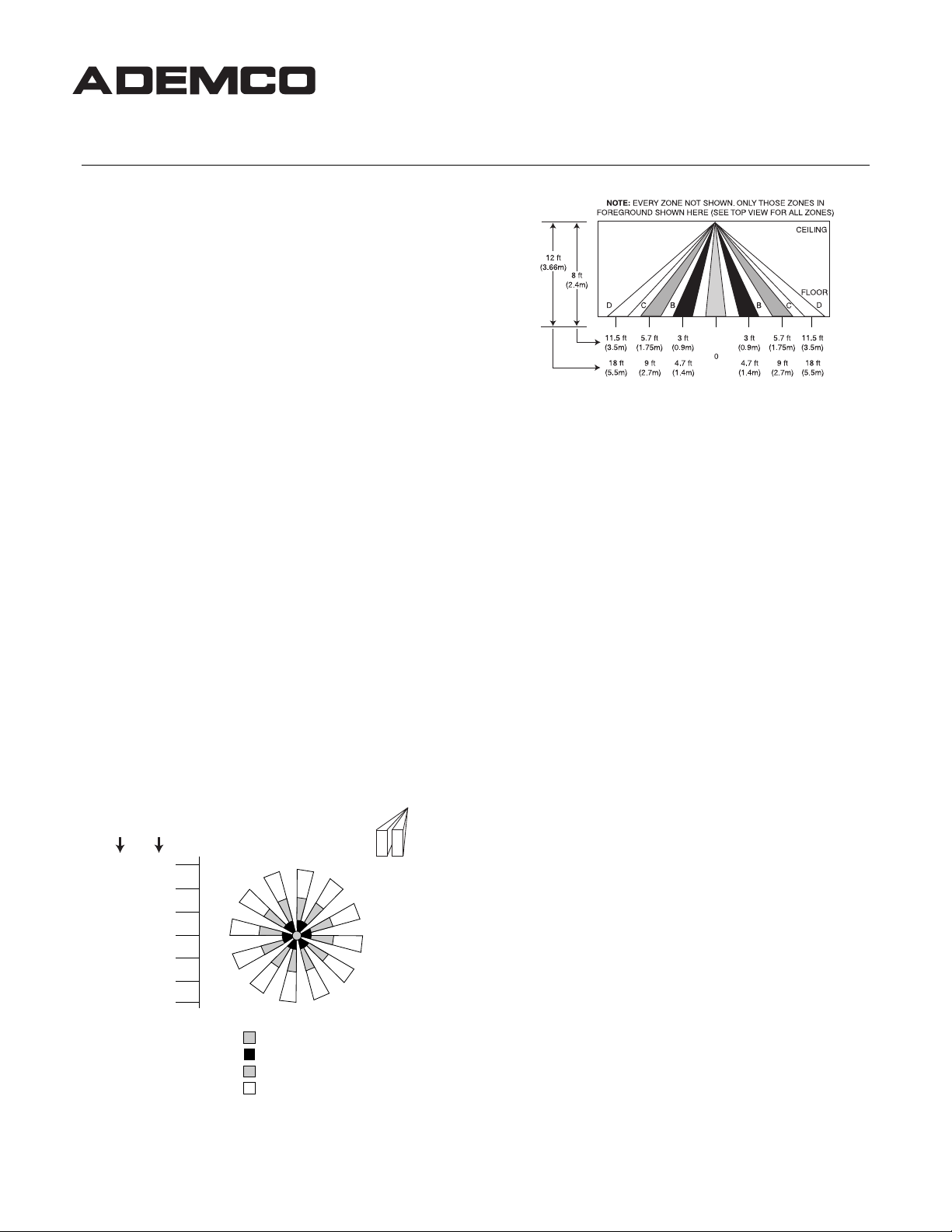
PROTECTION PATTERNS
The PIR’s protection pattern with the standard lens is shown
below.
An optional, easily changed, 34-zone lens (No. 997WD)
Note:
is available (outside of the U.S.A. only) that will provide greater
coverage when needed (see
LENS
).
12 ft
HEIGHT
(3.66m)
18 ft
(5.5m)
18 ft
(5.5m)
Detection Area – Standard Lens
8 ft
HEIGHT
(2.4m)
11.5 ft
(3.5m)
0
11.5 ft
(3.5m)
INTERCHANGEABLE OPTIONAL
TOP VIEW
TOP VIEW
CENTER ZONE
ZONES B (6 ZONES)
ZONES C (12 ZONES)
ZONES D (12 ZONES)
NOTE: EACH ZONE
CONSISTS OF TWO
FIELDS (INCLUDING
THE CENTER ZONE)
SIDE VIEW
SPECIFICATIONS
Detection Method:
Coverage:
23-ft (7m) diameter @ 8 ft (2.4m) height,
11.5-ft (3.5m) radius.
36-ft (11m) diameter @ 12-ft (3.7m) height,
18-ft (5.5m) radius.
With Optional Lens:
22-ft (6.7m) radius.
55-ft (16.76m) diameter @10-ft (3.1m)
height, 27.5-ft (8.4m) radius.
Pulse Count:
Detectable
Walk Rate:
Indicator:
Mounting
12-ft (3.7m) maximum for standard lens,
Height:
10-ft (3.1m) maximum for optional lens.
Voltage:
12VDC nominal (voltage reversal makes PIR
Alarm Relay:
Current Drain:
Standby
Capability:
4 hours of battery standby.
Operating
Temperature:
Operating
Humidity:
Up to 95% RH (max), non-condensing.
Dimensions:
Passive Infrared.
With Standard Lens:
44-ft (13.4m) diameter @ 8-ft height,
1- or 2-event, installer-selectable.
0.5 – 5ft/Sec (0.15 – 1.5m/Sec).
Red LED with enable/disable feature.
inoperative).
SPST, Form A, 0.5A max. contact rating @
30VDC. Reed relay, 15 ohm protective resistor.
17mA.
Power source should be capable of at least
32°F – 122°F (0°C – 50°C).
3-1/2” (89mm) diameter x 1” (25.4mm) high.
INSTALLING AND WIRING THE PIR
The ceiling on which the PIR is to be mounted must be firm and
vibration-free.
1.
Select a location
the lens in use. Wiring (from the control, etc.) to be connected
to the PIR should be brought to this location. The ceiling
wiring hole should be no more than 5/16” (8mm) in diameter.
2.
Remove the cover
turning it counterclockwise (to the left).
that will provide the coverage desired from
from the PIR by pressing it in gently and
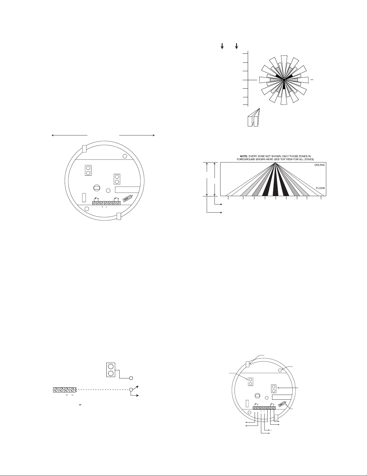
3.
Break out one of the two knockouts
that have been
provided for wire access (see Figure 3), and pass the wires
into the base of the PIR.
obstruct the detector’s field of view.
4.
Connect all wires
Caution: Be certain that wires do not
to the screw terminals (see Figure 3 for
wiring details). Seal all openings in the base with foam or RTV
(not supplied) to prevent drafts or insects from entering the
unit.
5. For walk-test purposes, initially set the LED to “on” (jumper
removed), and set Pulse Count “off” (jumper removed).
6.
Mount the PIR base
to the ceiling with two screws, using the
screw holes provided in the base of the PIR.
Important Note:
Optimum mounting orientation is shown in
Figure 1. Mount the PIR in such a manner that the likely path of
an intruder is in the direction shown. This will ensure maximum
effectiveness of the Alternate Polarity feature.
INTRUDER'S MOST LIKELY
DIRECTION OF MOTION
ON
PULSE
COUNT
DET
RELAY
LED
ALARM
12V
LED
OFF
Figure 1. Optimum Mounting Orientation
LED ENABLE/DISABLE
The detector is shipped with the Alarm LED disabled (LED
enable/disable plug in place). The LED should be enabled (for a
walk-test) by
removing
for location). To prevent the loss of the plug, we suggest you
install it on one pin when the plug is not in use. When the walktest is completed, the LED may be disabled, if desired (plug in
place).
The LED may also be controlled from a remote location, as
follows:
Remove the LED enable/disable plug. Connect a switched line to
the upper pin (#1) of the two LED pins that can be grounded or
opened (see Figure 2). Grounding pin #1 will disable the LED.
Disconnecting it from ground will enable the LED.
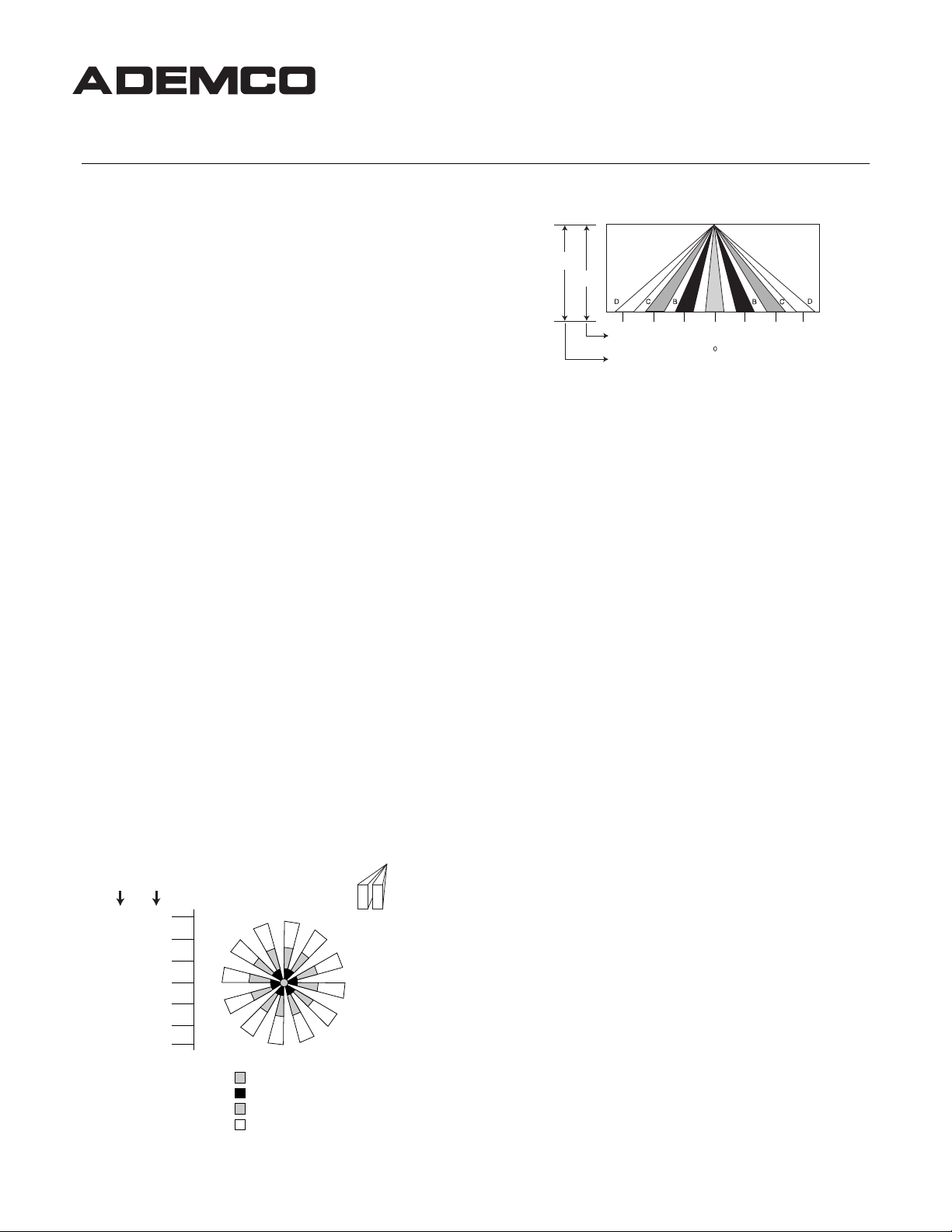
Detection Area – Optional 997WD Lens
(Lens available only outside of the U.S.A.)
RELAY
the LED enable/disable plug (see Figure 3
TOP VIEW
1 LED
DISABLE
TO A GROUND TERMINAL ON
12V
THE ASSOCIATED CONTROL OR TO
( - ) TERMINAL ON DETECTOR
ENABLE
Figure 2. Remote Control of LED
10 ft
(3.1m)
27.5 ft
(8.4m)
27.5 ft
(8.4m)
8 ft
HEIGHT
(2.4m)
22 ft
(6.7m)
0
22 ft
(6.7m)
NOTE: EACH ZONE
CONSISTS OF TWO
FIELDS (INCLUDING
THE CENTER ZONE)
ZONES A CENTER ZONE
ZONES B (6 ZONES)
ZONES C (12 ZONES)
ZONES D (12 ZONES)
ZONES E (12 ZONES)
HEIGHT
SIDE VIEW
10 ft
(3.1m)
8 ft
(2.4m)
EDCBA BCDE
13 ft
7 ft
7 ft
(2.1m)
8.75 ft
(2.67m)
3 ft
(0.9m)
3.75 ft
(1.14m)
13 ft
22 ft
(4m)
(6.7m)
16.25 ft
27.5 ft
(4.95m)
(8.4m)
3 ft
(2.1m)
(0.9m)
0
3.75 ft
(1.14m)
8.75 ft
(2.67m)
(4m)
16.25 ft
(4.95m)
22 ft
(6.7m)
27.5 ft
(8.4m)
TAMPER SWITCH
This PIR is equipped with a cover tamper switch. With cover
on, the switch is closed; when cover is removed, the switch
opens. The tamper terminals (see Figure 3) should be
connected to the control panel’s tamper loop.
PULSE COUNT OPTION
Each detector includes Pulse Count circuitry that is designed to
provide stability in adverse environments to minimize false
alarms. Two-event pulse count is provided by positioning the
jumper plug across the pulse count pins (see Figure 3 for
location). To select one-event pulse count (instant response),
remove the jumper plug. When programmed for 2-event pulse
count, the detector will signal an alarm within 3 or 4 steps,
since the processing logic requires more complex motion than
just a momentary event. When the detector verifies an
intrusion, the LED will light and the alarm relay contacts will
transfer, both conditions lasting for approximately 1 to 3
seconds (dependent upon signal strength).
To prevent the loss of the plug, we suggest you install it on one
pin when the plug is not in use.
PULSE COUNT
"ON" WITH PLUG
INSTALLED."OFF"
WITH PLUG
REMOVED.
TO CLOSED CIRCUIT
PROTECTIVE LOOP
ON
Figure 3. PC Board (in base of PIR)
RELAY
DET
KNOCKOUTS (2)
FOR WIRE ENTRY
LED
ALARM
NOT USED
12V
LED
OFF
TO SEPARATE
TAMPER CIRCUIT
- TO 12VDC
+ POWER SOURCE
MOUNTING
HOLES (2)
LED.
"OFF" WITH PLUG
INSTALLED. "ON"
WITH PLUG
REMOVED.
TAMPER SWITCH
(OPENS WHEN
COVER IS
REMOVED).
2

ACCESSING PC BOARD AFTER PIR IS MOUNTED
To enable or disable the alarm LED, or Pulse Count, you will need
to access the PC board located in the PIR. Remove the cover
from the PIR by pressing it in gently and turning it
counterclockwise (to the left).
To replace the cover, align the tabs on the cover's edge with the
notches on the base's rim, press the cover gently in, and turn it
clockwise (to the right).
Interchangeable Optional Lens (997WD)
(Available only outside of the U.S.A.)
This optional integrated lens/cover (where it is available) may be
used to to provide greater coverage for the 997.
Changing Lenses
Remove the existing cover on the PIR and replace it with the new
No. 997WD cover (which is equipped with the optional lens).
After changing lenses, a walk-test
be performed.
must
TEST PROCEDURES
Important:
power. Testing should be conducted with the protected area
cleared of all people. Disarm the protective system's control
during the test procedure to prevent reporting of unwanted
alarms.
Walk-Test
1. Pulse Count in the PIR must be “OFF” (jumper plug
2. With the cover installed on the PIR, walk through the
Note:
the alarm relay contacts remain open) for approximately 1 to 3
seconds after detecting motion.
3. If pulse count is to be used in this installation, install the
The absolute range of all PIR units is subject to variation
because of different types of clothing, backgrounds and ambient
temperature. For this reason, ensure that the most likely intruder
routes are well within the PIR's protective zones and that walktesting is carried out along these routes.
After the walk-test is complete, the LED may be disabled if
desired (LED enable/disable plug installed).
Two-minute warm-up time is required after applying
removed) to provide instant response. The Alarm LED must
be enabled at this time (LED jumper plug removed).
protective zones, observing that the PIR's LED lights
whenever motion is detected (the LED serves as a walk-test
indicator during this procedure).
With pulse count “OFF” (instant), the LED stays lit (and
pulse count jumper plug on the pulse count pins, and repeat
the walk test procedure. With pulse count “ON,” the LED
serves as an alarm indicator.
MAINTAINING PROPER OPERATION
In order to maintain the detector in proper working condition, it is
important that the following be observed by the user.
1.
Power should be provided at all times.
the unit will result in the alarm contacts reverting to an alarm
state. The unit's DC source should have standby power
available for at least 4 hours of operation during
emergencies.
2.
Units should never be relocated
assistance of the alarm service company.
3.
The physical surroundings of the protected area should
not be changed
. If furniture or stock is moved, or airconditioning or additional heating is installed, the system
may have to be readjusted by the alarm service company.
4.
Walk-tests should be conducted frequently (at least
to confirm continued proper coverage by each
weekly)
detector.
Loss of power to
without the advice or
TROUBLESHOOTING
INTERMITTENT ALARM (LED OPERATIVE)
Probable Causes:
A. Rapid temperature change. Check for electric or gas
heaters, open flames, electric arcs, etc..
Remedy:
B. Drafts causing drapes, light fixtures, display material to
move.
Remedy:
INTERMITTENT OR CONTINUOUS ALARM
Probable Causes:
A. DC voltage supplied to detector is inadequate, intermittent,
or polarity reversed.
Remedy:
B. Protective loop is interrupted (open).
Remedy:
LED INOPERATIVE
Probable Causes:
A. LED enable/disable plug is installed.
Remedy:
B. LED malfunction. Check for broken/shorted leads.
Remedy:
NO ALARM WHEN MOTION TAKES PLACE IN THE
PROTECTED AREA (LED DOES NOT LIGHT)
Probable Causes:
A. Detection area has changed. Possibly due to repositioned
furniture or equipment in the protected area.
Remedy:
Regular maintenance and inspection (at least annually) by
the installer and frequent testing by the user are vital to
continuous satisfactory operation of any alarm system.
The installer should assume the responsibility of developing
and offering a regular maintenance program to the user, as
well as acquainting the user with the proper operation and
limitations of the alarm system and its component parts.
Recommendations must be included for a specific program
of frequent testing (at least weekly) to ensure the system's
operation at all times.
Locate source and reposition detector if
necessary.
Eliminate source of motion.
Ensure that proper polarity and adequate voltage
is supplied and that wiring is intact (no opens or
shorts) and connections secure.
Determine whether interruption is in protective
loop wiring or at detector's alarm relay contacts.
Disconnect protective loop at detector relay
contact terminals and check continuity across
terminals. If absent at terminals (and proper
voltage is supplied to the detector), return unit for
service. If present, check protective loop wiring.
Remove LED enable/disable plug.
Return unit for service.
Caution customer about layout changes.
TO THE INSTALLER
3

THE LIMITATIONS OF YOUR PASSIVE
INFRARED MOTION DETECTOR
While the Passive Infrared Motion Detector is a highly reliable intrusion
detection device, it does not offer guaranteed protection against burglary.
Any intrusion detection device is subject to compromise or failure to warn for
a variety of reasons:
•
Passive Infrared Motion Detectors can only detect intrusion within the
designed ranges as diagrammed in this installation manual.
•
Passive Infrared Motion Detectors do not provide volumetric area
protection. They do create multiple beams of protection, and intrusion can
only be detected in unobstructed areas covered by those beams.
•
Passive Infrared Detectors cannot detect motion or intrusion that takes
place behind walls, ceilings, floors, closed doors, glass partitions, glass
doors, or windows.
•
Mechanical tampering, masking, painting or spraying of any material on
the lenses, windows or any part of the optical system can reduce the
detection ability of the Passive Infrared Motion Detector.
•
Passive Infrared Detectors sense changes in temperature; however, as
the ambient temperature of the protected area approaches the
temperature range of 90° to 105°F (32° to 40°C), the detection
performance can decrease.
•
This Passive Infrared Detector will not operate without appropriate DC
power connected to it, or if the DC power is improperly connected (i.e.,
reversed polarity connections).
•
Passive Infrared Detectors, like other electrical devices, are subject to
component failure. Even though this equipment is designed to last as long
as 10 years, the electronic components in it could fail at any time.
We have cited some of the most common reasons that a Passive Infrared
Motion Detector can fail to catch intrusion. However, this does not imply that
these are the only reasons, and therefore it is recommended that weekly
testing of this type of unit, in conjunction with weekly testing of the entire
alarm system, be performed to ensure that the detectors are working
properly.
Installing an alarm system may make the owner eligible for a lower insurance
rate, but an alarm system is not a substitute for insurance. Homeowners,
property owners and renters should continue to act prudently in protecting
themselves and continue to insure their lives and property.
We continue to develop new and improved protection devices. Users of
alarm systems owe it to themselves and their loved ones to learn about
these developments.
ADEMCO SIX-YEAR LIMITED WARRANTY
Alarm Device Manufacturing Company, a Division of Pittway Corporation,
and its divisions, subsidiaries and affiliates ("Seller"), 165 Eileen Way,
Syosset, New York 11791, warrants this PIR Detector to be in conformance
with its own plans and specifications and to be free from defects in materials
and workmanship under normal use and service for 72 months from the date
stamp control on the product. Seller's obligation shall be limited to replacing,
at its option, free of charge for materials or labor, a PIR which is proved not
in compliance with Seller's specifications or proves defective in materials or
workmanship under normal use and service. Seller shall have no obligation
under this Limited Warranty or otherwise if the PIR is altered or improperly
repaired or serviced by anyone other than Ademco factory service. In case
of defect, return the PIR to Ademco Distribution, Inc. or an authorized
Ademco distributor for an immediate replacement.
THERE ARE NO WARRANTIES, EXPRESS OR IMPLIED, OF
MERCHANTABILITY, OR FITNESS FOR A PARTICULAR PURPOSE OR
OTHERWISE, WHICH EXTEND BEYOND THE DESCRIPTION ON THE
FACE HEREOF. IN NO CASE SHALL SELLER BE LIABLE TO ANYONE
FOR ANY CONSEQUENTIAL OR INCIDENTAL DAMAGES FOR BREACH
OF THIS OR ANY OTHER WARRANTY, EXPRESS OR IMPLIED, OR
UPON ANY OTHER BASIS OF LIABILITY WHATSOEVER, EVEN IF THE
LOSS OR DAMAGE IS CAUSED BY THE SELLER'S OWN NEGLIGENCE
OR FAULT.
Seller does not represent that its PIR may not be compromised or
circumvented; that the PIR will prevent any personal injury or property loss
by burglary, robbery, fire or otherwise; or that the PIR will in all cases
provide adequate warning or protection. Buyer understands that a properly
installed and maintained alarm may only reduce the risk of a burglary,
robbery, fire or other events occurring without providing an alarm, but it is
not insurance or a guarantee that such will not occur or that there will be no
personal injury or property loss as a result. CONSEQUENTLY, SELLER
SHALL HAVE NO LIABILITY FOR ANY PERSONAL INJURY, PROPERTY
DAMAGE OR OTHER LOSS BASED ON A CLAIM THE PIR FAILED TO
GIVE WARNING. HOWEVER, IF SELLER IS HELD LIABLE, WHETHER
DIRECTLY OR INDIRECTLY, FOR ANY LOSS OR DAMAGE ARISING
UNDER THIS LIMITED WARRANTY OR OTHERWISE, REGARDLESS OF
CAUSE OR ORIGIN, SELLER'S MAXIMUM LIABILITY SHALL NOT IN
ANY CASE EXCEED THE PURCHASE PRICE OF THE PIR, WHICH
SHALL BE THE COMPLETE AND EXCLUSIVE REMEDY AGAINST
SELLER. This warranty replaces any previous warranties and is the only
warranty made by Seller on this PIR. No increase or alteration, written or
verbal, of the obligations of this Limited Warranty is authorized.
¬1l
N6206-1EN (
Part of N6206-1 8/99
165 Eileen Way, Syosset, New York 11791
Copyright © 1999 PITTWAY CORPORATION
)
®
N6206-1SP (
Part of N6206-1 8/99
)
997
Detector De Movimiento Infrarrojo Pasivo De Montaje En Techo
INSTRUCCIONES DE INSTALACION
INFORMACION GENERAL
Este detector de movimiento infrarrojo pasivo es una unidad de
montaje en techo que utiliza una lente Fresnel de 360
zonas y que ofrece un eficiente patrón de protección para
instalaciones comerciales y residenciales. La unidad detecta
cambios de temperatura bruscos y tenues dentro del área de
detección; por lo tanto, cuando un intruso cruza o accede a
cualquier zona, el cambio de energía infrarroja resultante es
detectado, generando un informe de alarma. Para obtener la
mejor cobertura instale el Infrarrojo Pasivo (PIR) de tal manera
que la ruta más probable de un intruso sea la dirección
mostrada en la Ilustración 1.
El detector incorpora un Contador de Impulsos de Polaridad
Alterna seleccionable por el instalador que proporciona
protección contra las falsas alarmas, y una opción de
habilitar/inhabilitar LED (seleccionable por el instalador).
CONSEJOS DE INSTALACION
No instale la unidad en lugares donde esté expuesta a la luz
•
solar directa ni directamente encima de grandes fuentes de
calor.
Asegúrese de que la zona de detección no tiene
•
obstrucciones (cortinas, pantallas, grandes muebles, plantas,
etc.) que puedan bloquear el patrón de cobertura.
Evite situar la unidad en zonas que contengan objetos que
•
puedan producir cambios bruscos de temperatura, como una
calefacción central, radiadores o conductos (o cualquier tipo
de calefactor), aparatos de aire acondicionado, llamas
abiertas, etc.
No monte la unidad sobre una superficie inestable.
•
Importante:
Evite tender el cableado de alarma cerca de
cables de alimentación eléctrica de gran actividad.
PATRONES DE PROTECCION
A continuación se muestra el patrón de protección del PIR con
la lente estándar.
Opción de lente de 34 zonas, (No. 997WD) la cual facilita
Nota:
una mayor cobertura si es necesario (véase LENTE OPCIONAL
INTERCAMBIABLE).
Diagrama de Cobertura ---- Lente estándar
VISTA SUPERIOR
ALTURA
3,66m
5,5m
18 ft
(5.5m)
ALTURA
2,4m
3,5m
11.5 ft
(3.5m)
VISTA SUPERIOR
0
ZONA CENTRAL
ZONAS B (6 ZONAS)
ZONAS C (12 ZONAS)
ZONAS D (12 ZONAS)
NOTA: CADA ZONA
CONSTA DE DOS
CAMPOS (INCLUYENDO
LA ZONA CENTRAL)
o
, 31-
NOTA: NO SE MUESTRAN TODAS LAS ZONAS. SOLO SE MUESTRAN
AQUELLAS ZONAS EN PRIMER PLANO (VER VISTA SUPERIOR PARA
TODAS LAS ZONAS).
3,66m
2,4m
VISTA LATERAL
1,75m
2,7m
0,8m
1,4m
3,5m
5,5m
0,8m
1,4m
1,75m
2,7m
TECHO
SUELO
3,5m
5,5m
ESPECIFICACIONES
Método de
Detección:
Cobertura:
Infrarrojo Pasivo.
Con Lente Estándar:
7m de diámetro a 2,4m de altura, radio 3,5m.
11m de diámetro a 3,7m de altura, radio 5,5m.
Con Lente Opcional:
13,4m de diámetro a 2,4m de altura, radio 6,7m.
16,76m de diámetro a 3,1m de altura, radio 8,4m.
Contador de
Impulsos:
1- o 2-eventos, seleccionable por el instalador.
Velocidad de
Paso Detectable:
Indicador:
0,15 - 1,5m/sg.
LED Rojo con opción habilitar/inhabilitar.
Altura de
Montaje:
3,7m máximo para lente estándar.
3,1m máximo para lente opcional.
Alimentación:
Relé de Alarma:
12VCC nominal (con la polaridad invertida el
PIR no será operativo).
SPST, Forma A, 0,5A max. a 30VCC. Relé
Reed, resistencia de protección de 15 ohmios.
Consumo:
17mA.
Capacidad en
Reposo:
La fuente de alimentación deberá tener una
capacidad de 4 horas de reserva de batería
como mínimo.
Temperatura de
Operación:
0°C – 50°C.
Humedad de
Operación:
Dimensiones:
Hasta 95% HR (max), sin condensación.
89mm diámetro x 25,4mm altura.
INSTALACION Y CABLEADO DEL PIR
La superficie del techo en la que se instale el PIR debe ser firme
y libre de vibraciones.
1. Seleccione la ubicación que le proporcione la cobertura
deseada para la lente que utilice. Deberá acercar el cable
(desde el control, etc.) a conectar al PIR hasta esta ubicación.
El orificio de cableado del techo no debe tener más de 8mm de
diámetro.
2. Retire la cubierta del PIR presionándola levemente y girándola
en sentido contrario a las agujas del reloj (hacia la izquierda).
3. Rompa una de las dos tapas desprendibles facilitadas para el
acceso del cableado (véase Ilustración 3), e introduzca los
cables en la base del PIR.
no obstruyen el campo de visión del detector.
: Asegúrese de que los cables
Aviso
4. Conecte todos los cables a los terminales (véase Ilust. 3 para
detalles del cableado). Selle todas las aberturas de la base con
espuma o RTV (no suministrado) para evitar que corrientes o
insectos accedan a la unidad.
5. Para la prueba de paso, configure el LED en posición ON (sin
puente), y el Contador de Impulsos en OFF (sin el puente).
6. Fije la base de la unidad en el techo con dos tornillos,
utilizando los orificios para tornillos de la base del PIR.
Nota Importante:
La orientación de montaje óptima se muestra
en la Ilustración 1. Instale el Infrarrojo Pasivo de tal manera que
la trayectoria más probable de un intruso esté en la dirección
mostrada. Esto asegurará la máxima eficacia del proceso de
señal de Polaridad Alterna.
RUTA MAS PROBABLE
DEL INTRUSO
CONTADOR
DE INPULSOS
"ON"
DET
LED
ALARMA
RELE
12V
LED
OFF
Ilustración 1. Orientación de Montaje Optima
HABILITAR/INHABILITAR LED
El detector se suministra con el LED de Alarma inhabilitado (el
puente de habilitar/inhabilitar del LED en su sitio). Debe habilitar
el LED (para la prueba de paso) retirando el puente de
habilitar/inhabilitar del LED (véase Ilust. 3 para ubicación). Para
evitar perder el puente, cuando no lo utiliza, sugerimos que
coloque el mismo en una de las patillas. Una vez completada la
prueba de paso, podrá inhabilitar el LED, (puente colocado).
También puede controlar el LED remotamente, de la siguiente
manera:
Retire el puente del LED. Conecte una línea conmutada a la
patilla superior (#1) de las dos patillas del LED que pueden
conectarse a tierra o mantenerse abiertas (véase Ilust. 2). La
patilla nº 1 de tierra inhabilitará el LED, desconectándola de tierra
habilitará el LED.
RELE
A TERMINAL DE TIERRA DEL
12V
CONTROL/COMUNICADOR
ASOCIADO O AL TERMINAL ( - )
DEL DETECTOR
Ilustración 2. Control Remoto del LED
1 LED
INHABILITAR
HABILITAR
DIAGRAMA DE PROTECCION – LENTE OPCIONAL 997WD
VISTA SUPERIOR
ALTURA
ALTURA
3,1m
2,4m
6,7m8,4m
0
6,7m8,4m
ZONAS A ZONA CENTRAL
ZONAS B (6 ZONAS)
ZONAS C (12 ZONAS)
0
ZONAS D (12 ZONAS)
ZONAS E (12 ZONAS)
2,1m
2,67m
4m
4,95m
0,9m
1,14m
TECHO
SUELO
6,7m
8,4m
NOTA: CADA ZONA
CONSTA DE DOS
CAMPOS (INCLUYENDO
LA ZONA CENTRAL)
NOTA: NO SE MUESTRAN TODAS LAS ZONAS. SOLO SE MUESTRAN AQUELLAS
ZONAS EN PRIMER PLANO (VER VISTA SUPERIOR PARA TODAS LAS ZONAS).
3,1m
2,4m
VISTA LATERAL
EDCBA BCDE
2,1m 0,9m
4m
6,7m
2,67m 1,14m
4,95m
8,4m
INTERRUPTOR ANTISABOTAJE
El Infrarrojo Pasivo está equipado con un interruptor
antisabotaje para la cubierta. Con la cubierta puesta, el
interruptor está cerrado; cuando se retira la cubierta, el
interruptor se abre. Los terminales antisabotaje (véase Ilust. 3)
deberán conectarse al lazo antisabotaje del panel de control.
OPCION DE CONTADOR DE IMPULSOS
Cada detector incluye un circuito Contador de Impulsos diseñado
para proporcionar estabilidad en entornos adversos minimizando así
las falsas alarmas. El contador de impulsos de dos eventos se
obtiene colocando el puente entre las patillas del contador de
impulsos (véase Ilust. 3 para la ubicación). Para seleccionar un
contador de impulsos de un evento (respuesta instantánea), quite el
puente. Si programa la unidad para 2 eventos, el detector indicará una
alarma a los 3 o 4 pasos, ya que la lógica del proceso requiere un
movimiento más complejo que un sólo evento momentáneo. Cuando
el detector verifica una intrusión, el LED se iluminará y los contactos
del relé de alarma transmitirán, ambas condiciones durante
aproximadamente 1 a 3 segundos (dependiendo de la fuerza de la
señal).
Para evitar perder el puente sugerimos que cuando no lo utilice
lo instale en una de las patillas.
2
 Loading...