

ADEMCO 710 User Manual
No.710
UNISTROBE WARNING LIGHT
GENERAL INFORMATION:
The No. 710 Unistrobe Warning Light can be installed indoors or outside to
provide brilliant,
the alarm system”bel 1” terminals .or other switched voltage source.
attention-getting flashes of light upon dctivation from
Physical:
Electrical: Voltage: 5 to l5V. DC
Width:
Height:
Depth:
Current :
Flash Rate:
4 3/8” (II.1 cm)
4 3/8!’ (II.1 cm)
3 l/Z” ( 8.9 cm)
Approximately 350 ma at 6V. DC
Approximately 250 ma at l2V. DC
Approximately 60 times per minute at 6V. DC (faster
at higher voltages up to l5V. DC max.)
INSTALLATION & WIRING:
TAMPER SWITCH (OPTIONAL):
If tampered installation is desired:
I .
Obtain a No. II2 or No. II3 Plunger Contact (use No.. 112 for a closed
circuit alarm system, No.
2.
Cbonect a #22 wire to each terminal of the switch.
3.
Insert switch in the tamper switch opening provided in the base of the
unit, with its terminals facing into the opening and wires exiting at
the corner of the opening. Snap switch into place.
II3 for an open circuit system).
WIRING:
TO MOUNT ON STANDARD 4 l/2” OUTLET BOX:
I .
2.
3.
?-he hole in the tamper plate provided. Thread the screw into the hole
at the corner of the outlet box.
plate (if used) under the base of the No.
4.
Place a similar screw through diagonally opposite hole A2 and fasten
that corner to the outlet box.
5.
of unit.
Use Diagram I in conjunction with the appropriate mounting procedure described below.
and BLACK (-1 leads.
Connect wiring as described under WIRING and as shown in Diagram I.
Position unit so that its “tamper switch corner” is at lower left when
unit is viewed from the front.
Place a 3/4 #8-32 Machine Screw (not provided) through hole Al at the
“tamper switch corner”
Insert plastic Decor Pluqs (provided) into the two front mounting holes
and (if a tamper switch is being used) through
www.PDF-Zoo.com
Note: Observe polarity with the RED (+I
The unit will not operate with reverse polarity.
See Diagram 2.
Before tightening, position the tamper
710 and then tighten the screw.
20
TO MOUNT ON BELL HOUSING, WALL OR OTHER STURDY SURFACE:
Note : Units such as the Ademco No. 1011 Bell in Box and No, 711 Electronic
Sirenahave holes already in their cabinets to accomodate the No. 710.
Use Diagram 2 Template to locate holes for drilling in the mounting sur-
I .
face, as follows:
For Front Mounting:
a.
(two I” #8 self-tapping screws accompany unit) and cut a wiring hole
(l/2” minimum diameter) at C.
For Rear Mounting:
b.
#8 self-tapping screws provided) and cut a wiring hole (l/2” min
at C.
Bring DC power source and (if used) tamper circuit wires to the unit
2.
throuqh hole C and.connect as described under WIRING and in Diagram
Position unit
3.
is viewed from front.
Mount unit. The #8 self-tapping screws provided may be used for front
4.
mounting (“A” holes) or rear mounting (“B” holes).
5. Insert plastic Decor Plugs (provided) into the two front
of unit.
SO
that ‘tamper switch corner” is at lower left when unit
Drill mounting holes at Al and A2 as required
Drill 3/16’ diameter holes at BI and B2 (to c
mounting holes
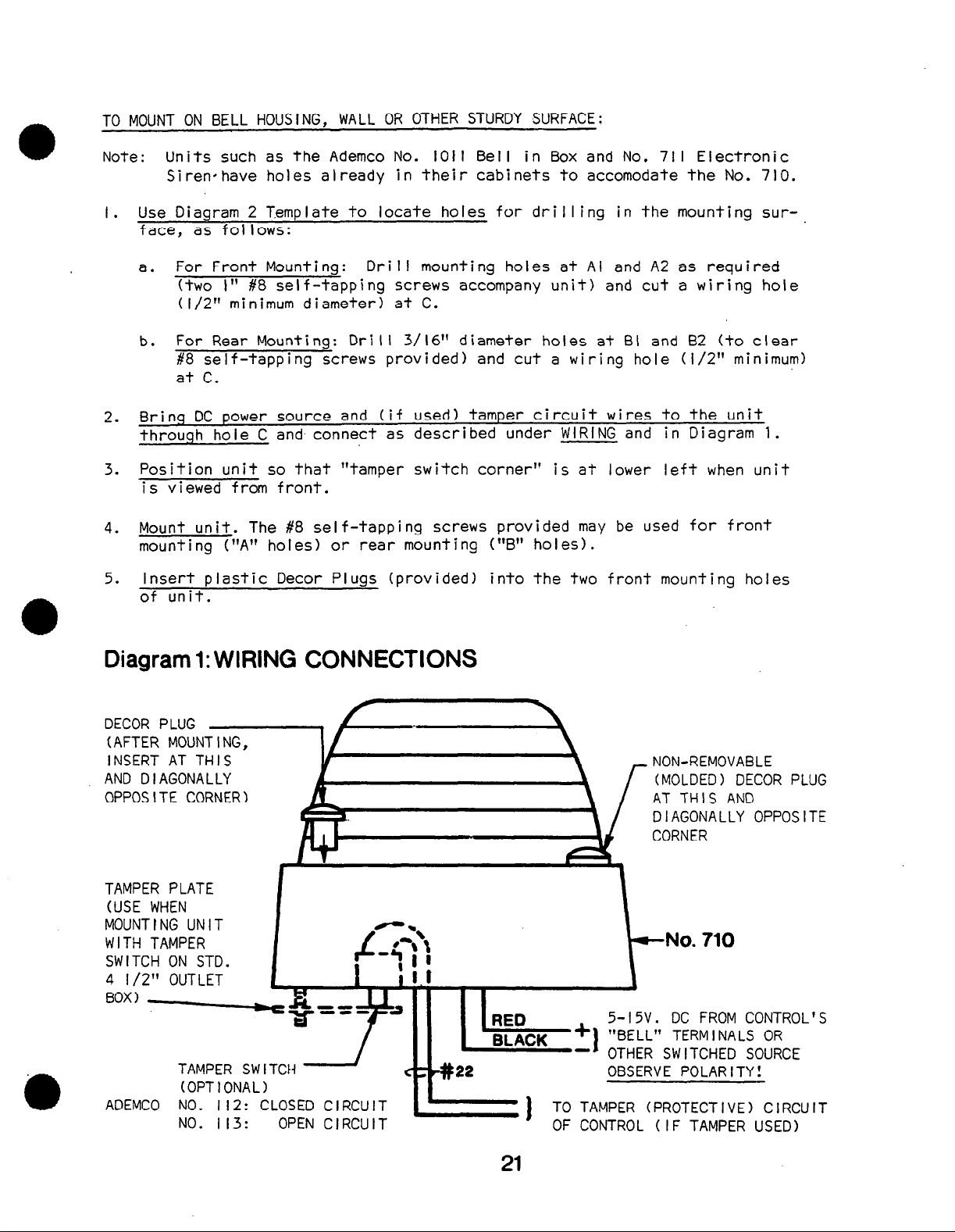
Diagram 1: WIRING CONNECTIONS
ear
mum)
-1
.
DECOR PLUG
(AFTER MOUNT I NG,
INSERT AT THIS
AND D I AGONALLY
OPPOSITE CORNER)
TAMPER PLATE
(USE WHEN
MOUNTING UNIT
WITH TAMPER
SWITCH ON STD.
4 l/2” OUTLET
BOX) .--
TAMPER SW ITCH -
(OPTIONAL)
ADEMCO NO. 112: CLOSED C
NO. 113: OPEN C
RCU
RCU
21
NON-REMOVABLE
(MOLDED) DECOR PLUG
AT THIS AND
DIAGONALLY OPPOSITE
CORNER
-No. 710
5-l5V. DC FROM CONTROL
“BELL” ’ TERM I NALS OR
OTHER
OBSERVE POLARITY!
TO TAMPER (PROTECTIVE) CIRCUIT
OF CONTROL ( IF TAMPER USED)
SWITCHED SOURCE
.‘S
www.PDF-Zoo.com
 Loading...